WO2014106932A1 - プレス部品とその製造方法および製造装置 - Google Patents
プレス部品とその製造方法および製造装置 Download PDFInfo
- Publication number
- WO2014106932A1 WO2014106932A1 PCT/JP2013/084299 JP2013084299W WO2014106932A1 WO 2014106932 A1 WO2014106932 A1 WO 2014106932A1 JP 2013084299 W JP2013084299 W JP 2013084299W WO 2014106932 A1 WO2014106932 A1 WO 2014106932A1
- Authority
- WO
- WIPO (PCT)
- Prior art keywords
- metal plate
- die
- vertical wall
- blank holder
- shape
- Prior art date
- Legal status (The legal status is an assumption and is not a legal conclusion. Google has not performed a legal analysis and makes no representation as to the accuracy of the status listed.)
- Ceased
Links
Images















Classifications
-
- B—PERFORMING OPERATIONS; TRANSPORTING
- B21—MECHANICAL METAL-WORKING WITHOUT ESSENTIALLY REMOVING MATERIAL; PUNCHING METAL
- B21D—WORKING OR PROCESSING OF SHEET METAL OR METAL TUBES, RODS OR PROFILES WITHOUT ESSENTIALLY REMOVING MATERIAL; PUNCHING METAL
- B21D22/00—Shaping without cutting, by stamping, spinning, or deep-drawing
- B21D22/20—Deep-drawing
-
- B—PERFORMING OPERATIONS; TRANSPORTING
- B62—LAND VEHICLES FOR TRAVELLING OTHERWISE THAN ON RAILS
- B62D—MOTOR VEHICLES; TRAILERS
- B62D25/00—Superstructure or monocoque structure sub-units; Parts or details thereof not otherwise provided for
- B62D25/04—Door pillars ; windshield pillars
-
- B—PERFORMING OPERATIONS; TRANSPORTING
- B21—MECHANICAL METAL-WORKING WITHOUT ESSENTIALLY REMOVING MATERIAL; PUNCHING METAL
- B21D—WORKING OR PROCESSING OF SHEET METAL OR METAL TUBES, RODS OR PROFILES WITHOUT ESSENTIALLY REMOVING MATERIAL; PUNCHING METAL
- B21D22/00—Shaping without cutting, by stamping, spinning, or deep-drawing
- B21D22/20—Deep-drawing
- B21D22/22—Deep-drawing with devices for holding the edge of the blanks
-
- B—PERFORMING OPERATIONS; TRANSPORTING
- B21—MECHANICAL METAL-WORKING WITHOUT ESSENTIALLY REMOVING MATERIAL; PUNCHING METAL
- B21D—WORKING OR PROCESSING OF SHEET METAL OR METAL TUBES, RODS OR PROFILES WITHOUT ESSENTIALLY REMOVING MATERIAL; PUNCHING METAL
- B21D22/00—Shaping without cutting, by stamping, spinning, or deep-drawing
- B21D22/20—Deep-drawing
- B21D22/26—Deep-drawing for making peculiarly, e.g. irregularly, shaped articles
-
- B—PERFORMING OPERATIONS; TRANSPORTING
- B21—MECHANICAL METAL-WORKING WITHOUT ESSENTIALLY REMOVING MATERIAL; PUNCHING METAL
- B21D—WORKING OR PROCESSING OF SHEET METAL OR METAL TUBES, RODS OR PROFILES WITHOUT ESSENTIALLY REMOVING MATERIAL; PUNCHING METAL
- B21D53/00—Making other particular articles
- B21D53/88—Making other particular articles other parts for vehicles, e.g. cowlings, mudguards
-
- B—PERFORMING OPERATIONS; TRANSPORTING
- B21—MECHANICAL METAL-WORKING WITHOUT ESSENTIALLY REMOVING MATERIAL; PUNCHING METAL
- B21J—FORGING; HAMMERING; PRESSING METAL; RIVETING; FORGE FURNACES
- B21J5/00—Methods for forging, hammering, or pressing; Special equipment or accessories therefor
- B21J5/02—Die forging; Trimming by making use of special dies ; Punching during forging
-
- B—PERFORMING OPERATIONS; TRANSPORTING
- B21—MECHANICAL METAL-WORKING WITHOUT ESSENTIALLY REMOVING MATERIAL; PUNCHING METAL
- B21K—MAKING FORGED OR PRESSED METAL PRODUCTS, e.g. HORSE-SHOES, RIVETS, BOLTS OR WHEELS
- B21K7/00—Making railway appurtenances; Making vehicle parts
- B21K7/12—Making railway appurtenances; Making vehicle parts parts for locomotives or vehicles, e.g. frames, underframes
-
- B—PERFORMING OPERATIONS; TRANSPORTING
- B62—LAND VEHICLES FOR TRAVELLING OTHERWISE THAN ON RAILS
- B62D—MOTOR VEHICLES; TRAILERS
- B62D65/00—Designing, manufacturing, e.g. assembling, facilitating disassembly, or structurally modifying motor vehicles or trailers, not otherwise provided for
-
- B—PERFORMING OPERATIONS; TRANSPORTING
- B21—MECHANICAL METAL-WORKING WITHOUT ESSENTIALLY REMOVING MATERIAL; PUNCHING METAL
- B21D—WORKING OR PROCESSING OF SHEET METAL OR METAL TUBES, RODS OR PROFILES WITHOUT ESSENTIALLY REMOVING MATERIAL; PUNCHING METAL
- B21D24/00—Special deep-drawing arrangements in, or in connection with, presses
- B21D24/04—Blank holders; Mounting means therefor
-
- B—PERFORMING OPERATIONS; TRANSPORTING
- B21—MECHANICAL METAL-WORKING WITHOUT ESSENTIALLY REMOVING MATERIAL; PUNCHING METAL
- B21D—WORKING OR PROCESSING OF SHEET METAL OR METAL TUBES, RODS OR PROFILES WITHOUT ESSENTIALLY REMOVING MATERIAL; PUNCHING METAL
- B21D5/00—Bending sheet metal along straight lines, e.g. to form simple curves
- B21D5/04—Bending sheet metal along straight lines, e.g. to form simple curves on brakes making use of clamping means on one side of the work
- B21D5/045—With a wiping movement of the bending blade
-
- Y—GENERAL TAGGING OF NEW TECHNOLOGICAL DEVELOPMENTS; GENERAL TAGGING OF CROSS-SECTIONAL TECHNOLOGIES SPANNING OVER SEVERAL SECTIONS OF THE IPC; TECHNICAL SUBJECTS COVERED BY FORMER USPC CROSS-REFERENCE ART COLLECTIONS [XRACs] AND DIGESTS
- Y10—TECHNICAL SUBJECTS COVERED BY FORMER USPC
- Y10T—TECHNICAL SUBJECTS COVERED BY FORMER US CLASSIFICATION
- Y10T29/00—Metal working
- Y10T29/49—Method of mechanical manufacture
- Y10T29/49616—Structural member making
- Y10T29/49623—Static structure, e.g., a building component
-
- Y—GENERAL TAGGING OF NEW TECHNOLOGICAL DEVELOPMENTS; GENERAL TAGGING OF CROSS-SECTIONAL TECHNOLOGIES SPANNING OVER SEVERAL SECTIONS OF THE IPC; TECHNICAL SUBJECTS COVERED BY FORMER USPC CROSS-REFERENCE ART COLLECTIONS [XRACs] AND DIGESTS
- Y10—TECHNICAL SUBJECTS COVERED BY FORMER USPC
- Y10T—TECHNICAL SUBJECTS COVERED BY FORMER US CLASSIFICATION
- Y10T428/00—Stock material or miscellaneous articles
- Y10T428/12—All metal or with adjacent metals
- Y10T428/1241—Nonplanar uniform thickness or nonlinear uniform diameter [e.g., L-shape]
Definitions
- the present invention relates to a pressed part having a hat cross section and curved in an L shape in plan view in the longitudinal direction, and a manufacturing method and a manufacturing apparatus thereof.
- the skeleton structure of a car body of an automobile is composed of a plurality of skeleton members formed by press-molding a metal plate (in the following description, the case where the material metal plate is a steel plate). These skeletal parts are extremely important parts for ensuring collision safety of automobiles. Side sills, cross members, front pillars and the like are known as skeleton members.
- the skeleton member has a hat cross-sectional shape including a top plate portion, two vertical walls connected to both sides of the top plate portion, and two flange portions connected to the two vertical walls, respectively. Many of the skeletal members have this hat cross-sectional shape in part or all thereof.
- the frame member is desired to have high strength in order to improve collision safety performance and reduce the weight of the vehicle body.
- FIG. 19 is a perspective view of an example of the skeleton member 0 having a hat cross section and a straight shape in the longitudinal direction in a plan view and a side view.
- 20A and 20B are explanatory diagrams of the front pillar 0-1 as an example of a skeleton member having a hat cross section.
- FIG. 20A is a perspective view
- FIG. 20B is a plan view.
- FIG. 21 is a perspective view showing the component 1 having a hat cross section and a shape curved in an L shape in plan view in the longitudinal direction.
- “in plan view” means a direction orthogonal to the top plate portion which is the widest planar portion of the member (in FIG. 20A, the direction of the white arrow, and FIG. ) Means that the skeletal member 0-1 is viewed from the direction perpendicular to the paper surface.
- the skeleton member 0 such as a side sill has a substantially straight shape in the longitudinal direction as illustrated in FIG.
- the front pillar 0-1 has a shape as shown in FIGS. 20 (a) and 20 (b). That is, the front pillar 0-1 includes a hat cross section and a shape curved in an L shape in plan view in the longitudinal direction, as shown in FIG.
- the skeleton member 0 has a substantially straight shape in the longitudinal direction, and is thus mainly manufactured by bending.
- the skeleton member 0 does not change greatly in the longitudinal direction of the cross section, and even if it is made of a high-strength steel sheet having low extensibility, cracks and wrinkles are unlikely to occur during pressing, and is easy to form.
- Patent Document 1 discloses a method of bending a press part having a hat cross section. The method disclosed by Patent Document 1 manufactures a pressed part having a hat cross section but having a substantially straight shape in the longitudinal direction.
- FIG. 22 is a perspective view showing a press part 1 which is manufactured by bending and has a hat cross section and has a shape curved in an L shape in the longitudinal direction.
- the component 1 having the hat cross section shown in FIG. 21 and curved in an L shape in the longitudinal direction is bent by the method disclosed in Patent Document 1, as shown in FIG. 22, the outer flange portion of the bent portion 1a ( (Part A) Wrinkles occur.
- the component 1 is generally formed by drawing press.
- draw forming a raw steel plate is formed using a die, a punch, and a blank holder in order to control the amount of inflow of the raw metal plate and suppress the generation of wrinkles.
- FIG. 23 is an explanatory view showing the component 2 curved in an L shape in the longitudinal direction to be molded
- FIG. 23 (a) is a perspective view
- FIG. 23 (b) is a top view
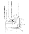
- FIG. 24 is a plan view showing the shape of the raw steel plate 3 and the wrinkle holding region B in the raw steel plate 3 in the case of drawing.
- 25 (a) to 25 (d) are cross-sectional views showing a die structure for drawing and a drawing process.
- FIG. 26 is a perspective view of the drawn panel 5 that has been drawn.
- a die 41, Molding is performed using the punch 42 and the blank holder 43.
- the material steel plate 3 shown in FIG. 24 is disposed between the punch 42 and the blank holder 43 and the die 41.
- the wrinkle holding region B (hatched portion in FIG. 24) around the raw steel plate 3 is strongly pressed by the blank holder 43 and the die 41.
- the die 41 is relatively moved in the direction of the punch 42.
- the material steel plate 3 is finally pressed against the punch 42 by the die 41 to process the material steel plate 3, thereby forming the diaphragm panel 5 shown in FIG.
- the wrinkle holding region B around the steel plate 3 is strongly pressed by the blank holder 43 and the die 41.
- the material steel plate 3 is stretched in a state where tension is applied to a region inside the wrinkle holding region in the material steel plate 3.
- the molded diaphragm panel 5 is cut off unnecessary portions around it, and the component 2 shown in FIGS. 23A and 23B is manufactured.
- the vertical walls 22 and 24 shown in FIG. 23 (a) are formed at the same time. For this reason, the material steel plate 3 in the portion formed on the top plate portion 21 does not move much during the forming process, and the material flows from both sides of the top plate portion 21 as shown in FIGS. 25 (b) to 25 (d). Thus, the vertical walls 22 and 24 are formed.
- the flange portion (D portion in FIG. 26) inside the curved portion 5a that curves in an L shape in plan view in the diaphragm panel 5 is in a so-called stretch flange molding, and is a high-strength steel sheet having low extensibility. Then, cracking occurs.
- a high-strength steel sheet having a tensile strength of 590 MPa or more has little elongation, so that it is difficult to process without causing cracks in the D part.
- FIG. 27 is a plan view for explaining the material flow in the drawing.
- the material steel plate of the portion formed on the top plate portion 11 does not move so much. As shown in FIG. 27, the material is formed by flowing material from both sides of the top plate portion 11.
- the material steel plate 3 of the portion (D portion in FIGS. 26 and 27) formed on the inner peripheral side of the bending portion 1a moves from the inside to the outside of the curvature of the bending portion 1a, and in the radial direction of the bending portion 1a. It is greatly stretched to form a so-called stretch flange molding. For this reason, a crack occurs in a high-strength steel sheet having low extensibility.
- part C in FIG. 26 has a shape that is greatly projected at the corner on the outer peripheral side of the curved part 1a, so that the material steel sheet is greatly stretched, and, like part D, cracking occurs in the high-strength steel sheet having low extensibility. appear.
- a high-strength steel plate having low extensibility particularly a material steel plate 3 made of a high-strength steel plate having a tensile strength of 590 MPa or more, for parts curved in an L shape in the longitudinal direction.
- a relatively low-strength steel plate excellent in the strength was used as the material steel plate 3. For this reason, it is necessary to increase the plate thickness in order to ensure a predetermined strength, which is contrary to the request for weight reduction of the vehicle body.
- the object of the present invention is to press-form a material metal plate having a tensile strength of 200 to 1600 MPa, particularly a material metal plate made of a high-strength steel plate having a tensile strength of 590 MPa or more, to have a hat cross section and to be longitudinal in a plan view. It is an object of the present invention to provide a technique capable of manufacturing a press part having an L-shaped hat cross-sectional shape by having a curved part that is curved without generating wrinkles or cracks and with a high yield.
- a hat shape that includes a top plate portion, two vertical walls connected to both sides of the top plate, and two flanges connected to each of the two vertical walls by pressing the metal plate.
- a method for manufacturing a pressed part comprising: Place the material metal plate between the punch and blank holder and the pad, die and bending mold, A portion formed on the top plate portion of the material metal plate is pressed against the punch by the pad, and is further sandwiched outside the curved portion than a portion formed on the top plate portion of the material metal plate.
- the portion formed on the top plate portion of the material metal plate is pressed against the punch by the pad, and further, the L-shaped curved portion is formed from the portion formed on the top plate portion of the material metal plate.
- the vertical wall and the flange portion on the inner peripheral side of the bending portion are not formed, so that the material metal plate being formed is from the inner peripheral side of the bending portion. Only the portion of the metal plate that is formed on the top plate portion flows into the inner peripheral side of the curved portion. Therefore, unlike the case of drawing, the portion formed on the inner peripheral side of the curved portion in the raw metal plate does not move so much from the inner peripheral side to the outer peripheral side of the curvature of the curved portion in the forming process.
- the entire length of the material metal plate is bent when the longitudinal tip of the material metal plate flows into the inner peripheral side of the curved portion, and the flange portion on the inner peripheral side of the curved portion tends to be compressed.
- the amount of elongation of the flange portion on the inner peripheral side of the curved portion is greatly reduced as compared with drawing.
- the top plate portion and the flange portion on the outer peripheral side also flow inwardly of the curved portion, so that the compressive stress remains. Accordingly, the material is greatly stretched in the process of forming the vertical wall and the flange portion on the outer peripheral side of the curved portion, and the corner portion which is the meeting portion between the vertical wall on the outer peripheral side of the curved portion and the top plate portion also retains compressive stress. Therefore, the required material extensibility is reduced as compared with the case of drawing formed from a state without compression stress.
- the material metal plate is greatly stretched when the prior art drawing is performed, and the bending that causes cracking when a high-strength metal plate (for example, a high-tensile steel plate with a tensile strength of 590 MPa or more) is used. It is possible to reduce the elongation of the material metal plate at the corner part, which is the meeting part of the flange part on the inner peripheral side of the part and the vertical wall on the outer peripheral side of the curved part and the top plate part, so the extensibility is low Even if a high-strength metal plate is used, it can be formed without cracking.
- a high-strength metal plate for example, a high-tensile steel plate with a tensile strength of 590 MPa or more
- the punch has a shape including a shape on the plate thickness back side of each of the flange portions connected to the vertical wall located on the inner peripheral side of the top plate portion, the vertical wall, and the L-shaped curved portion.
- the blank holder has a shape including a shape on the plate thickness rear surface side of the flange portion connected to the vertical wall located on the outer peripheral side of the curved portion, and the pad is arranged so as to face the blank holder.
- the die has a shape including a shape on the plate thickness surface side of the top plate portion, and the die has a shape on the plate thickness surface side of each of the vertical wall located on the outer peripheral side of the curved portion and the flange portion connected to the vertical wall.
- the bending mold has a shape including a shape of a vertical wall located on the inner peripheral side of the bending portion and a shape of the plate thickness surface side of each flange portion connected to the vertical wall.
- the blank holder is fixed so as not to move relative to the punch so that the press part formed with the blank holder is pressed against the die and not pressed.
- the press part is taken out from the mold by separating the pad, the die and the bending die relative to the blank holder and the punch.
- the manufacturing method of the press part described in any one of the items up to the item).
- the material metal plate is a high-tensile steel plate having a plate thickness of 0.8 mm or more and 3.2 mm or less, and a tensile strength of 590 MPa or more and 1800 MPa or less.
- the width of the top plate portion is 30 mm or more and 400 mm or less in plan view
- the height of the vertical wall is 300 mm or less in side view
- the curvature on the inner peripheral side of the curved portion in plan view is 5 mm.
- a punch and a blank holder, and a pad, a die, and a bending die that are arranged to face the punch and the blank holder are provided.
- the material metal plate is pressed, and the top plate portion and the top plate
- An L-shaped hat having a hat-shaped cross section composed of two vertical walls connected to both sides and two flanges connected to each of the two vertical walls and having a curved portion curved in the longitudinal direction in plan view
- a press part manufacturing apparatus for forming a press part having a cross-sectional shape or a press part having the L-shaped hat cross-sectional shape in a part thereof, The pad presses and sandwiches the portion formed on the top plate portion of the material metal plate against the punch, and the blank holder is more than the portion formed on the top plate portion of the material metal plate.
- a portion that is outside the curved portion is pressed against the die and sandwiched, and the bending die moves relatively in the direction in which the punch is disposed to process the material metal plate, thereby allowing the inner portion of the curved portion to be processed.
- the second forming for forming the vertical wall on the outer peripheral side of the curved portion and the flange portion connected to the vertical wall by moving the material metal plate relatively moving in the arranged direction.
- a press part manufacturing method comprising a lock mechanism for fixing the blank holder so as not to move relative to the punch at the time of mold release after completion of molding. apparatus.
- Item (7) or (8) comprising: a sub-base configured to support the pad and the die so as to be movable up and down and integrated with the bending mold; and a die base configured to support the sub-base so as to freely enter and exit.
- Equipment for manufacturing pressed parts described in 1. (10) A sub-base configured to support the die so as to be movable up and down and to be integrated with the bending mold, and a die base that supports the pad so as to be moved up and down and supports the sub-base so as to freely enter and exit.
- a press part having a shape curved in an L shape in the longitudinal direction in a plan view A press-formed body using a high-tensile steel plate having a plate thickness of 0.8 mm or more and 3.2 mm or less and a tensile strength of 590 MPa or more and 1800 MPa or less as a raw metal plate,
- the width of the top plate portion is 30 mm or more and 400 mm or less in plan view
- the height of the vertical wall is 300 mm or less in side view
- the curvature of the inner peripheral side of the curved portion is 5 mm or more in plan view.
- a reduction rate of the plate thickness ⁇ (plate thickness maximum value ⁇ plate thickness minimum value) / plate thickness maximum value ⁇ ⁇ 100 is 15% or less.
- a material metal plate having a tensile strength of 200 to 1600 MPa is press-formed to have a hat cross section and to be longitudinal in a plan view.
- An L-shaped press part can be manufactured without generating wrinkles or cracks and with a high yield.
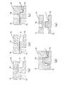
- FIGS. 1 (a) to 1 (e) are cross-sectional views showing a mold configuration and a molding process according to the present invention.
- 2 (a) to 2 (e) are cross-sectional views showing another mold configuration and molding process according to the present invention.
- FIG. 3A is a plan view showing the shape before forming the material metal plate
- FIG. 3B is a plan view showing the shape in the process of forming the material metal plate.
- FIG. 4 is a plan view showing a material flow in the present invention.
- FIG. 5 (a) to FIG. 5 (d) are explanatory views showing an example of a mold used in the present invention.
- 6 (a) to 6 (d) are explanatory views showing another example of the mold used in the present invention.
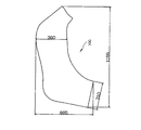
- FIGS. 9A to 9C are a front view, a plan view, and a right side view, respectively, showing the press part 1 to be molded in Comparative Examples 1 to 3 and Examples 1 to 3.
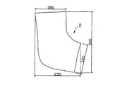
- FIG. 10 is a plan view showing the shape of the material metal plate used in Comparative Examples 1 to 3.
- FIG. 11 is a plan view showing the shape of the material metal plate used in Examples 1-3.
- FIG. 12 is a perspective view showing the configuration of the mold used in Examples 1 to 3.
- FIG.13 (a) is a top view which shows the shape of the raw material metal plate used in Example 4
- FIG.13 (b) is a perspective view of a press-formed product.
- Fig.14 (a) is a top view which shows the shape of the raw material metal plate used in Example 5
- FIG.14 (b) is a perspective view of a press-formed product.
- FIG. 15 is a plan view showing the shape of the material metal plate used in Example 6.
- FIG. 16 (a) to 16 (c) are a front view, a plan view, and a right side view, respectively, showing the intermediate shape formed in the sixth embodiment.
- FIG. 17 (a) to 17 (c) are a front view, a plan view, and a right side view, respectively, showing the shapes of the pressed parts formed in Example 6.
- FIG. FIG. 18 is a perspective view showing a mold configuration for carrying out molding according to the present invention in Example 6.
- FIG. 19 is a perspective view of an example of a skeleton member having a hat cross section and having a straight shape in the longitudinal direction in a plan view and a side view.
- 20A and 20B are explanatory views of a front pillar that is a skeleton member having a hat cross section.
- FIG. 20A is a perspective view
- FIG. 20B is a plan view.
- FIG. 21 is a perspective view showing a component having a hat cross section and curved in an L shape in the longitudinal direction in plan view.
- FIG. 22 is a perspective view showing a state in which a press part having a hat cross section and having a shape curved in an L shape in the longitudinal direction is manufactured by bending.
- FIG. 23 is an explanatory view showing a part curved in an L shape in the longitudinal direction to be molded, FIG. 23 (a) is a perspective view, and FIG. 23 (b) is a top view.
- FIG. 24 is a plan view showing the shape of the material metal plate and the wrinkle holding area in the material metal plate in the case of drawing.
- 25 (a) to 25 (d) are cross-sectional views showing a die structure for drawing and a drawing process.
- FIG. 26 is a perspective view of a drawn diaphragm panel.
- FIG. 27 is a plan view for explaining the material flow in the drawing.
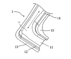
- Press part 1 As illustrated in FIG. 21 described above, the pressed part 1 has a curved section 1a having a hat cross section and curved in an L shape in the longitudinal direction in a plan view.
- the press part 1 has a hat-shaped cross section including a top plate portion 11, vertical walls 12 and 14 connected to both sides of the top plate portion 11, and flange portions 13 and 15 connected to the vertical walls 12 and 14, respectively. At the same time, it is bent in the longitudinal direction (the direction of the double arrow in FIG. 3) by the bending portion 1a, thereby having an L-shape in plan view.
- the press part 1 is a material that is generally used in a skeleton member for automobiles, and is made of a high-tensile steel plate having a plate thickness of 0.8 mm or more and 3.2 mm or less and a tensile strength of 590 MPa or more and 1800 MPa or less. It is composed of a metal plate.
- the material metal plate preferably has a tensile strength of 200 MPa or more and 1800 MPa or less, but a tensile strength of 500 MPa or more, and further 590 MPa or more. It is more preferable because the plate thickness can be reduced and parts can be reduced in weight, and more preferably 700 MPa or more.
- the inflow resistance of the material metal plate is reduced when the inner peripheral vertical wall 14 and flange portion 15 of the curved portion 1a are formed. It becomes large and the inflow to the inner peripheral side of the bending part 1a of a raw material metal plate becomes inadequate. For this reason, it is desirable that the width of the top plate portion 11 be 400 mm or less. On the other hand, if the width of the top plate portion 11 is too narrow, a pad pressurizing device such as a gas cushion must be made small, so that a sufficient pad pressing force cannot be secured. For this reason, it is desirable for the width
- the inflow resistance of the material metal plate increases when the inner peripheral side vertical wall 14 and the flange portion 15 of the curved portion 1a are formed. Inflow to the inner peripheral side of the curved portion 1a of the metal plate becomes insufficient. For this reason, it is desirable for the height of the vertical walls 12 and 14 to be 300 mm or less.
- the curvature on the inner peripheral side of the bending portion 1a is too small in plan view, when the flange portion 15 on the inner peripheral side of the bending portion 1a is formed, the material metal plate flows into the inner peripheral side of the bending portion 1a. Therefore, it is desirable that the curvature of the vertical wall 14 on the inner peripheral side of the bending portion 1a is 5 mm or more in plan view.
- the width of the top plate portion 11 is 30 mm or more and 400 mm or less in plan view
- the height of the vertical walls 12 and 14 is 300 mm or less in side view
- the inner peripheral side of the bending portion 1a in plan view.
- the curvature is preferably 5 mm or more.
- the reduction rate of the thickness of the pressed part 1 ⁇ (plate thickness maximum value ⁇ plate thickness minimum value) / plate thickness maximum value ⁇ ⁇ 100 is 15% or less.
- the press part 1 having such a low sheet thickness reduction rate has not existed so far. Since the plate thickness reduction rate of the pressed part 1 which is a structural member of the automobile body is thus low, it has excellent collision safety performance and is composed of a high-tensile steel plate having a tensile strength of 590 MPa to 1800 MPa. The weight of the vehicle body can be reduced.
- FIGS. 1A to 1E are cross-sectional views showing a mold configuration and a molding process according to the present invention.
- the metal mold shown in FIGS. 1 (a) to 1 (e) is used in order to form a pressed part 1 by performing press forming on a material metal plate.
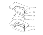
- This mold includes a punch 72 and a blank holder 73, and a pad 74, a die 71 and a bending die 75 that are arranged to face the punch 72 and the blank holder 73.
- the punch 72 has a shape including the shape of the platen back side of each of the top plate part 11 of the press part 1, the vertical wall 14 and the flange part 15 located on the inner peripheral side of the curved part 1a.
- the blank holder 73 has a shape including the shape on the back side of the plate thickness of the flange portion 13 connected to the vertical wall 12 located on the outer peripheral side of the curved portion 1a.
- the pad 74 has a shape including the shape on the thickness surface side of the top plate portion 11 so as to face the blank holder 73.
- the die 71 has a shape including the shape on the plate thickness surface side of each of the vertical wall 12 and the flange portion 13 located on the outer peripheral side of the curved portion 1a.
- the bending die 75 has a shape including the shape on the plate thickness surface side of each of the vertical wall 14 and the flange portion 15 located on the inner peripheral side of the bending portion 1a.
- 2 (a) to 2 (e) are cross-sectional views showing another mold configuration and molding process according to the present invention.
- FIG. 1 differs from the mold shown in FIG. 1 in that a lock mechanism 76 (described later) is mounted on the punch 72 and a bending mold 75 is mounted on a sub-base (not shown).
- a lock mechanism 76 (described later) is mounted on the punch 72 and a bending mold 75 is mounted on a sub-base (not shown).
- the lock mechanism 76 is configured by a pin that is arranged so as to freely enter and exit the punch 72.
- the lock mechanism 76 is completely accommodated in the punch 72 from the start of molding to the bottom dead center of the molding (FIGS. 2A to 2D), and goes out to the blank holder 73 side at the bottom bottom of the molding.
- the holder 73 is fixed to the punch 72.
- the lock mechanism 76 causes the molded press part 1 to be damaged by the pad pressure by lifting the die 75, the pad 74 and the sub-base while releasing the mold while the blank holder 73 is fixed to the punch 72 at the time of releasing. prevent.
- a mechanism for releasing (fixing) the positional relationship between the pad 74, the sub-base (bending mold 75), and the die 75 (drawing mold) may be used.
- the pad 74 may be fixed to the sub-base, and at the same time, the die 75 (drawing die) may be fixed to the pad 74 or the sub-base to be released, or (b) the spacer is inserted. By doing so, the space between the blank holder 73 and the pad 74 may be fixed and released, or (c) the positional relationship between the pad 74 and the bending die 75 may be fixed (held) and released. Good.
- the subbase will be described later.
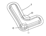
- FIG. 3A is a plan view showing the shape of the material metal plate 8 before forming
- FIG. 3B is a plan view showing the shape of the material metal plate 8 in the forming process
- FIG. 4 is a plan view showing a material flow in the present invention.
- the material metal plate 8 having the shape shown in FIG. 3A is disposed between the punch 72 and the blank holder 73, the pad 74, the die 71, and the bending die 75. To do.
- the portion formed on the top plate portion 11 of the material metal plate 8 is pressed against the punch 72 by the pad 74 and pressed and sandwiched, and the top plate of the material metal plate 8 is also pressed.
- the portion that is outside the curved portion 1 a than the portion that is formed on the portion 11 is pressed against the die 71 by the blank holder 73 and pressed and clamped.
- the bending die 75 is moved relatively in the direction in which the punch 72 is disposed to process the material metal plate 8 to longitudinally move the inner peripheral side of the bending portion 1a.
- the material metal plate 8 is formed into the shape shown in FIG.
- the flange portion (D portion) on the inner peripheral side of the bending portion 1a The material metal plate 8 does not move so much from the inside to the outside of the curvature of the curved portion 1a during the molding process, and the longitudinal tip of the material metal plate 8 flows into the inner peripheral side of the curved portion 1a. As a result, the entire material metal plate 8 is bent. And the flange part 15 (D part) inside the curved part 1a used as the inner side of the bending becomes a compression tendency. For this reason, the amount of elongation of the flange portion 15 (D portion) on the inner peripheral side of the curved portion 1a during molding is significantly reduced as compared with drawing.
- the blank metal plate 8 is pressed against the die 71 by the blank holder 73 and pressurized. While maintaining the sandwiched state, the die 71 and the blank holder 73 are moved relative to the material metal plate 8 in the direction in which the blank holder 73 is disposed, and the material metal plate 8 is processed so that the curved portion 1a is formed. The outer peripheral side vertical wall 12 and the flange portion 13 are formed. In this way, the pressed part 1 shown in FIG. 3 is formed.
- the portion formed on the top plate portion 11 and the flange portion 15 also flow into the inner peripheral side of the bending portion 1a and become longer. Since the compressive stress remains in the contraction direction, the corner portion (C in FIG. 4) is a meeting portion between the vertical wall 12 and the top plate 11 on the outer peripheral side of the curved portion 1a that is greatly stretched during the molding process. Part) is also formed into a shape protruding from the state in which the compressive stress remains. For this reason, the extensibility of the required material becomes small compared with the case of the draw forming formed from a state without compressive stress.
- the bending portion 75 is bent to form the inner peripheral side portion and the longitudinal tip portion of the bending portion 1a. Since the wrinkle holding area required for drawing and forming is not required, the material metal plate 8 can be made small, and forming with a high material yield becomes possible.
- the blank holder 73 is held by, for example, the lock mechanism 76.
- the blank holder 73 is fixed so as not to move relative to the punch 72, and the blank holder 73 is pressed against the die 71 so that the press-formed product 1 after molding is not pressed.
- the pad 74, the die 71, and the bending die 75 are separated from each other and then taken out. Thereby, the press part 1 after shaping
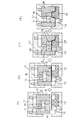
- FIG. 5 (a) to FIG. 5 (d) are explanatory views showing an example of a mold used in the present invention.
- the lock mechanism 76 is omitted in FIGS.
- the bending die 75, the die (drawing die) 71, and the pad 74 are directly supported by the die base 77, and each of them is driven independently with respect to the die base 77. Since this mold does not use a frame or the like that supports the bending mold 75 and the drawing mold 73, the entire mold can be reduced in size.
- FIG. 6 (a) to 6 (d) are explanatory views showing another example of the mold used in the present invention.
- This mold has a structure in which the sub-base 75 holds the pad 74 and the die 71 (drawing die), and the eccentric load of the pad 74 and the die 71 (drawing die) is received by the sub-base 75 integrated with the bending die.
- improvement to mold deformation can be achieved from the mold example shown in FIG.
- FIG. 7 (a) to 7 (d) are explanatory views showing another example of the mold used in the present invention, and FIG. 8 is an exploded perspective view of the mold.
- This die can incorporate the pad 74 in the die base 77 instead of the sub base 75, thereby avoiding the load burden of the pad 74 on the sub base 75. Since the vertical load applied to the sub-base is only received from the integrated bending mold, the deformation of the sub-base mold can be improved from the mold example shown in FIG.
- the molds illustrated in FIGS. 5A to 5D, 6A to 6D, and 7A to 7D are all manufactured according to the present development.
- the mold has a structure that is particularly effective for carrying out the method, the structure that suppresses the deformation of the mold affects the cost and size of the mold.
- What structure should be used may be appropriately determined in consideration of the rigidity required for the mold in consideration of the strength of the material steel plate.
- FIGS. 9 (a) to 9 (c) are a front view, a plan view, and a right side view, respectively, showing the press part 1 to be molded in Comparative Examples 1 to 3 and Examples 1 to 3.
- FIG. FIG. 10 is a plan view showing the shape of the material metal plate 8 used in Comparative Examples 1-3.
- FIG. 11 is a plan view showing the shape of the material metal plate 8 used in Examples 1-3.
- FIG. 12 is a perspective view showing the configuration of the mold used in Examples 1 to 3.
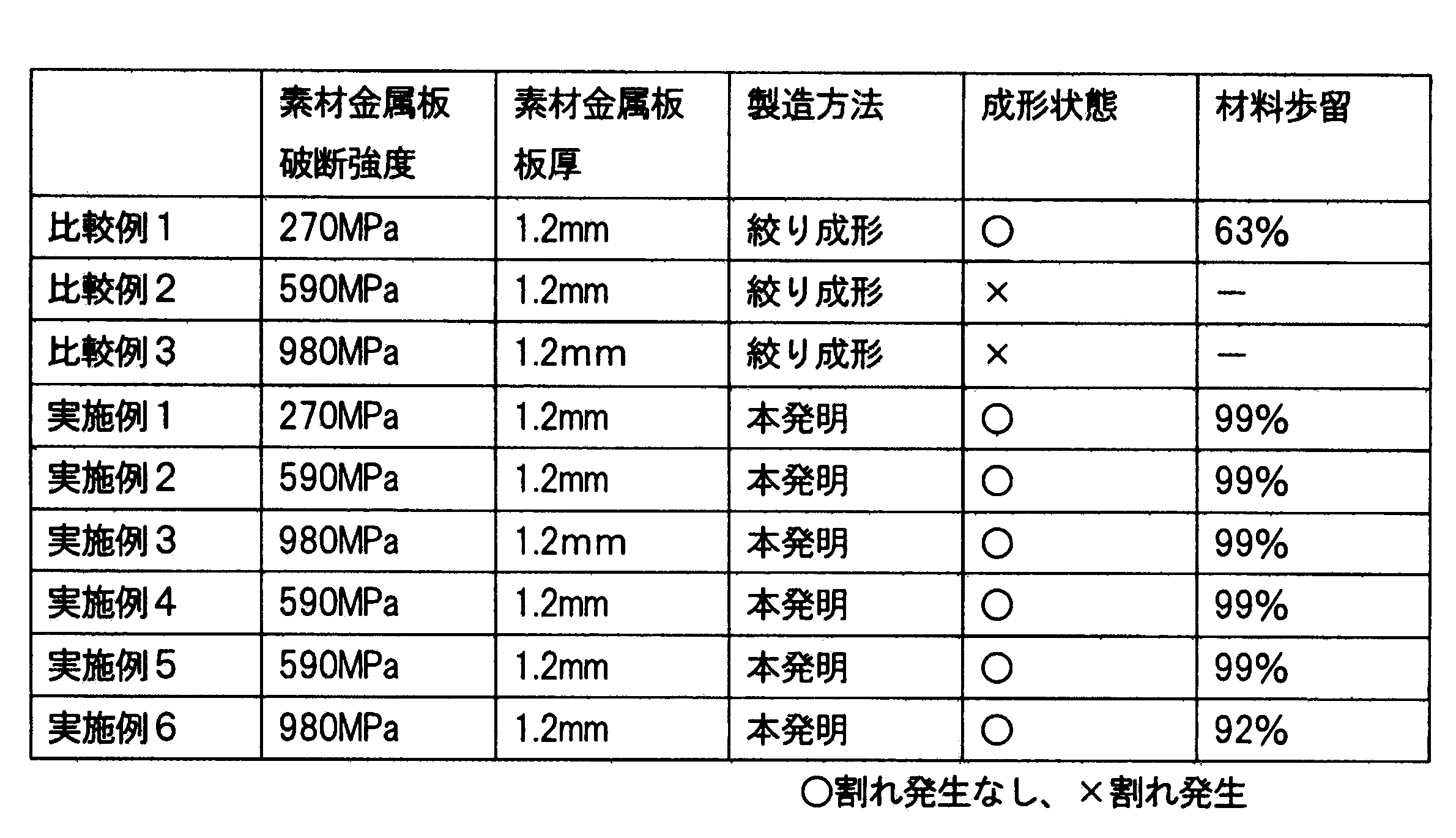
- Table 1 summarizes the results of Comparative Examples 1 to 3 and Examples 1 to 6.
- the press part 1 having the shape shown in FIGS. 9A to 9C is used as a material metal plate, the breaking strength is 270, 590, and 980 MPa, and the plate thickness is 1
- Each steel sheet was manufactured by a conventional drawing method and a method according to the present invention.
- the unit of the numerical values in FIGS. 9 to 11 is mm.
- the material yield in Table 1 is the ratio of the material that became a part to the material metal plate.
- Comparative Example 1 and Example 1 are examples in which a low strength steel plate excellent in extensibility at break strength of 270 MPa was used as a raw metal plate, and both could be formed without cracking, but the material yield was It was confirmed that Example 1 was very high and advantageous compared to Comparative Example 1.
- Comparative Examples 2 and 3 and Examples 2 and 3 are examples where pressing was performed using a high-strength steel plate having low extensibility as a raw metal plate. According to Examples 2 and 3, it was possible to mold well without cracking.
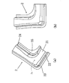
- FIG. 13 (a) is a plan view showing the shape of the material metal plate 8 used in Example 4, and FIG. 13 (b) is a perspective view of the press-formed product 1.
- FIG. 13 (b) is a plan view showing the shape of the material metal plate 8 used in Example 4, and
- FIG. 13 (b) is a perspective view of the press-formed product 1.
- Example 4 the press part 1 having the shape shown in FIG. 13B was formed using a pre-processed breaking strength of 590 MPa and a plate thickness of 1.2 mm as the material metal plate shown in FIG. This is an example. It was confirmed that even if such a metal plate having a non-flat shape was used, it could be satisfactorily formed.
- FIG. 14A is a plan view showing the shape of the material metal plate 8 used in Example 5, and FIG. 14B is a perspective view of the press-formed product 1.
- Example 5 is an example in which the shape shown in FIG. 14B is formed using a flat steel plate having a breaking strength of 590 MPa and a plate thickness of 1.2 mm shown in FIG. Although the top plate portion is not flat, the top plate portion was processed by a pad, so that the top plate portion could be molded well.
- FIG. 15 is a plan view showing the shape of the material metal plate used in Example 6, and FIGS. 16 (a) to 16 (c) are front views showing intermediate shapes formed in Example 6, respectively.
- FIG. 17 (a) to FIG. 17 (c) are a front view, a plan view, and a right side view, respectively, showing the shape of the press part 1 formed in Example 6.
- FIG. 18 is a perspective view showing a mold configuration for carrying out molding according to the present invention in Example 6.
- Example 6 the complicated shape shown in FIGS. 17 (a) to 17 (c) was formed using a high-strength steel plate having a tensile strength of 980 MPa and low plate thickness of 1.2 mm as a raw metal plate. It is an example.
- a material metal plate having the shape shown in FIG. 15 is formed into an intermediate shape shown in FIGS. 16 (a) to 16 (c) by the present invention using a mold having the structure shown in FIG.
- the pressed part 1 having the shape shown in FIGS. 17 (a) to 17 (c) could be formed well without cracks and wrinkles.
Landscapes
- Engineering & Computer Science (AREA)
- Mechanical Engineering (AREA)
- Chemical & Material Sciences (AREA)
- Combustion & Propulsion (AREA)
- Transportation (AREA)
- Manufacturing & Machinery (AREA)
- Shaping Metal By Deep-Drawing, Or The Like (AREA)
- Bending Of Plates, Rods, And Pipes (AREA)
Abstract
Description
(1)素材金属板にプレス加工を行うことにより、天板部と、該天板の両側につながる2つの縦壁と、該2つの縦壁それぞれにつながる2つのフランジとにより構成されるハット形状の断面を有するとともに平面視で長手方向へ湾曲する屈曲部を有することによりL字状ハット断面形状を有するプレス部品、もしくは、該L字状ハット断面形状をその一部に有するプレス部品に成形するプレス部品の製造方法であって、
パンチおよびブランクホルダーと、パッド、ダイおよび曲げ型との間に素材金属板を配置し、
該素材金属板における前記天板部に成形される部分を前記パッドにより前記パンチに押し付けて挟持し、さらに、前記素材金属板における前記天板部に成形される部分より前記湾曲部の外側になる部分を前記ブランクホルダーで該ダイに押し付けて挟持し、
前記曲げ型を前記パンチが配置されている方向へ相対的に移動して前記素材金属板を加工することにより、前記湾曲部の内周側の縦壁と、該縦壁につながるフランジ部とを成形した後に、
前記素材金属板を該ブランクホルダーで該ダイに押し付けて挟持する状態を維持しながら、前記ダイと前記ブランクホルダーを該素材金属板に対して該ブランクホルダーが配置されている方向へ相対的に移動して前記素材金属板を加工することにより、前記湾曲部の外周側の縦壁と該縦壁につながるフランジ部を成形することによって、前記プレス部品を成形すること
を特徴とするプレス部品の製造方法。
(2)前記パンチは、前記天板部、前記縦壁、および前記L字状の湾曲部の内周側に位置する縦壁につながる前記フランジ部それぞれの板厚裏面側の形状を含む形状を有し、前記ブランクホルダーは、前記湾曲部の外周側に位置する縦壁につながるフランジ部の板厚裏面側の形状を含む形状を有し、前記パッドは、該ブランクホルダーに対向するように前記天板部の板厚表面側の形状を含む形状を有し、前記ダイは、前記湾曲部の外周側に位置する縦壁、および該縦壁につながるフランジ部それぞれの板厚表面側の形状を含む形状を有するとともに、前記曲げ型は、前記湾曲部の内周側に位置する縦壁、および該縦壁につながるフランジ部それぞれの板厚表面側の形状を含む形状を有することを特徴とする(1)項に記載されたプレス部品の製造方法。
(3)前記素材金属板は、予加工された金属板である(1)項または(2)項に記載されたプレス部品の製造方法。
(4)前記プレス部品の成形後に、前記ブランクホルダーを前記パンチに対して相対的に動かないように固定して、前記ブランクホルダーが成形された該プレス部品を前記ダイに押し付け加圧しないようにして、前記ブランクホルダーと前記パンチに対し、前記パッドと前記ダイおよび前記曲げ型とを相対的に離すことにより前記プレス部品を金型の中から取り出すことを特徴とする(1)項から(3)項までのいずれか1項に記載されたプレス部品の製造方法。
(5)前記素材金属板は、板厚が0.8mm以上でかつ3.2mm以下で、さらに引張強度が590MPa以上で1800MPa以下の高張力鋼板であることを特徴とする(1)項から(4)項までのいずれか1項に記載されたプレス部品の製造方法。
(6)平面視で前記天板部の幅は30mm以上400mm以下であり、側面視で前記縦壁の高さは300mm以下であるとともに、平面視で前記湾曲部の内周側の曲率は5mm以上であることを特徴とする(1)項から(5)項までのいずれか1項に記載されたプレス部品の製造方法。
(7)パンチおよびブランクホルダーと、該パンチおよびブランクホルダーに対向して配置されるパッド、ダイおよび曲げ型とを備え、素材金属板にプレス加工を行って、天板部と、該天板の両側につながる2つの縦壁と、該2つの縦壁それぞれにつながる2つのフランジとにより構成されるハット形状の断面を有するとともに平面視で長手方向へ湾曲する湾曲部を有することによりL字状ハット断面形状を有するプレス部品、もしくは、該L字状ハット断面形状をその一部に有するプレス部品に成形するプレス部品の製造装置であって、
前記パッドは、前記素材金属板における前記天板部に成形される部分を前記パンチに押し付けて挟持し、さらに、前記ブランクホルダーは、前記素材金属板における前記天板部に成形される部分より前記湾曲部の外側になる部分を前記ダイに押し付けて挟持し、前記曲げ型が前記パンチが配置されている方向へ相対的に移動して前記素材金属板を加工することにより、前記湾曲部の内周側の縦壁と、該縦壁につながるフランジ部とを成形する第1の成形を行うこと、および、
該第1の成形を行った後に、前記ブランクホルダーが前記素材金属板を前記ダイに押し付けて挟持する状態を維持しながら、前記ダイと前記ブランクホルダーが該素材金属板に対して該ブランクホルダーが配置されている方向へ相対的に移動して前記素材金属板を加工することにより、前記湾曲部の外周側の縦壁と該縦壁につながるフランジ部を成形する第2の成形を行うことによって、前記プレス部品を成形すること
を特徴とするプレス部品の製造装置。
(8)成形完了後の離型時に、前記ブランクホルダーを前記パンチに対して相対的に動かないように固定するロック機構を備えることを特徴とする(7)項に記載されたプレス部品の製造装置。
(9)前記パッドおよび前記ダイを昇降自在に支持するとともに前記曲げ型と一体に構成されるサブベースと、該サブベースを出入り自在に支持するダイベースとを有する(7)項または(8)項に記載されたプレス部品の製造装置。
(10)前記ダイを昇降自在に支持するとともに前記曲げ型と一体に構成されるサブベースと、前記パッドを昇降自在に支持するとともに前記サブベースを出入り自在に支持するダイベースとを有する(7)項または(8)項に記載されたプレス部品の製造装置。
(11)天板部と、該天板部の両側につながる2つの縦壁と、該縦壁にそれぞれつながる2つのフランジ部とにより構成されるハット形状の断面を有するとともに、湾曲部を有することにより湾曲して平面視で長手方向へL字状に湾曲した形状を有するプレス部品であって、
板厚が0.8mm以上でかつ3.2mm以下で、さらに引張強度が590MPa以上で1800MPa以下の高張力鋼板を素材金属板とするプレス成形体であること、
平面視で前記天板部の幅は30mm以上400mm以下であり、側面視で前記縦壁の高さは300mm以下であるとともに、平面視で前記湾曲部の内周側の曲率は5mm以上であること、および
板厚の減少率{(板厚最大値-板厚最小値)/板厚最大値}×100は15%以下であること
を特徴とするプレス部品。
(12)自動車車体の構造部材であるAピラーインナーパネルである(11)項に記載されたプレス部品。
1.プレス部品1
上述した図21にその形状を例示するように、プレス部品1は、ハット断面を有するとともに平面視で長手方向へL字状に湾曲した湾曲部1aを有する。
2.プレス部品の製造方法および製造装置
図1(a)~図1(e)は、本発明に係る金型構成と成形工程を示す断面図である。
図3(a)は、素材金属板8の成形前の形状を示す平面図であり、図3(b)は素材金属板8の成形過程での形状を示す平面図である。さらに、図4は、本発明における材料の流れを示す平面図である。
この金型は、サブベース75でパッド74とダイ71(絞り型)を抱える構造とし、パッド74とダイ71(絞り型)の偏芯荷重を、曲げ型と一体のサブベース75で受けることにより、上記図5に示す金型例より金型変形への改善が図れる。
比較例1~3および実施例1~3では、図9(a)~図9(c)に示す形状のプレス部品1を、素材金属板として破断強度が270,590,980MPaで板厚が1.2mmの鋼板を用い、製造方法として従来技術である絞り成形法,本発明法により、それぞれ製造した。
1a 湾曲部
8 素材金属板
11 天板部
12 湾曲部の外周側の縦壁
13 湾曲部の外周側のフランジ部
14 湾曲部の内周側の縦壁
15 湾曲部の内周側のフランジ部
2 部品
21 天板
22 L字状湾曲の外側の縦壁
23 L字状湾曲の外側の縦壁につながるフランジ
24 L字状湾曲の内側の縦壁
25 L字状湾曲の内側の縦壁につながるフランジ
3 素材金属板
41 ダイ
42 パンチ
43 ブランクホルダー
5 絞りパネル
6 絞りパネル
71 ダイ
72 パンチ
73 ブランクホルダー
74 パッド
75 曲げ型
Claims (12)
- 素材金属板にプレス加工を行うことにより、天板部と、該天板の両側につながる2つの縦壁と、該2つの縦壁それぞれにつながる2つのフランジとにより構成されるハット形状の断面を有するとともに平面視で長手方向へ湾曲する湾曲部を有することによりL字状ハット断面形状を有するプレス部品、もしくは、該L字状ハット断面形状をその一部に有するプレス部品に成形するプレス部品の製造方法であって、
パンチおよびブランクホルダーと、パッド、ダイおよび曲げ型との間に素材金属板を配置し、
該素材金属板における前記天板部に成形される部分を前記パッドにより前記パンチに押し付けて挟持し、さらに、前記素材金属板における前記天板部に成形される部分より前記湾曲部の外側になる部分を前記ブランクホルダーで該ダイに押し付けて挟持し、
前記曲げ型を前記パンチが配置されている方向へ相対的に移動して前記素材金属板を加工することにより、前記湾曲部の内周側の縦壁と、該縦壁につながるフランジ部とを成形した後に、
前記素材金属板を該ブランクホルダーで該ダイに押し付けて挟持する状態を維持しながら、前記ダイと前記ブランクホルダーを該素材金属板に対して該ブランクホルダーが配置されている方向へ相対的に移動して前記素材金属板を加工することにより、前記湾曲部の外周側の縦壁と該縦壁につながるフランジ部を成形することによって、前記プレス部分を成形すること
を特徴とするプレス部品の製造方法。 - 前記パンチは、前記天板部、前記湾曲部の内周側に位置する縦壁および該縦壁につながる前記フランジ部それぞれの板厚裏面側の形状を含む形状を有し、前記ブランクホルダーは、前記湾曲部の外周側に位置する縦壁につながるフランジ部の板厚裏面側の形状を含む形状を有し、前記パッドは、該ブランクホルダーに対向するように前記天板部の板厚表面側の形状を含む形状を有し、前記ダイは、前記湾曲部の外周側に位置する縦壁、および該縦壁につながるフランジ部それぞれの板厚表面側の形状を含む形状を有するとともに、前記曲げ型は、前記湾曲部の内周側に位置する縦壁、および該縦壁につながるフランジ部それぞれの板厚表面側の形状を含む形状を有することを特徴とする請求項1に記載されたプレス部品の製造方法。
- 前記素材金属板は、予加工された金属板である請求項1または請求項2に記載されたプレス部品の製造方法。
- 前記プレス部品の成形後に、前記ブランクホルダーを前記パンチに対して相対的に動かないように固定して、前記ブランクホルダーが成形された該プレス部品を前記ダイに押し付け加圧しないようにして、前記ブランクホルダーと前記パンチに対し、前記パッドと前記ダイおよび前記曲げ型とを相対的に離すことにより前記プレス部品を金型の中から取り出すことを特徴とする請求項1から請求項3までのいずれか1項に記載されたプレス部品の製造方法。
- 前記素材金属板は、板厚が0.8mm以上でかつ3.2mm以下で、さらに引張強度が590MPa以上で1800MPa以下の高張力鋼板であることを特徴とする請求項1から請求項4までのいずれか1項に記載されたプレス部品の製造方法。
- 平面視で前記天板部の幅は30mm以上400mm以下であり、側面視で前記縦壁の高さは300mm以下であるとともに、平面視で前記湾曲部の内周側の曲率は5mm以上であること
を特徴とする請求項1から請求項5までのいずれか1項に記載されたプレス部品の製造方法。 - パンチおよびブランクホルダーと、該パンチおよびブランクホルダーに対向して配置されるパッド、ダイおよび曲げ型とを備え、素材金属板にプレス加工を行って、天板部と、該天板の両側につながる2つの縦壁と、該2つの縦壁それぞれにつながる2つのフランジとにより構成されるハット形状の断面を有するとともに平面視で長手方向へ湾曲する湾曲部を有することによりL字状ハット断面形状を有するプレス部品、もしくは、該L字状ハット断面形状をその一部に有するプレス部品に成形するプレス部品の製造装置であって、
前記パッドは、前記素材金属板における前記天板部に成形される部分を前記パンチに押し付けて挟持し、さらに、前記ブランクホルダーは、前記素材金属板における前記天板部に成形される部分より前記湾曲部の外側になる部分を前記ダイに押し付けて挟持し、前記曲げ型が前記パンチが配置されている方向へ相対的に移動して前記素材金属板を加工することにより、前記湾曲部の内周側の縦壁と、該縦壁につながるフランジ部とを成形する第1の成形を行うこと、および、
該第1の成形を行った後に、前記ブランクホルダーが前記素材金属板を前記ダイに押し付けて挟持する状態を維持しながら、前記ダイと前記ブランクホルダーが該素材金属板に対して該ブランクホルダーが配置されている方向へ相対的に移動して前記素材金属板を加工することにより、前記湾曲部の外周側の縦壁と該縦壁につながるフランジ部を成形する第2の成形を行うことによって、前記プレス部品を成形すること
を特徴とするプレス部品の製造装置。 - 成形完了後の離型時に、前記ブランクホルダーを前記パンチに対して相対的に動かないように固定するロック機構を備えることを特徴とする請求項7に記載されたプレス部品の製造装置。
- 前記パッドおよび前記ダイを昇降自在に支持するとともに前記曲げ型と一体に構成されるサブベースと、該サブベースを出入り自在に支持するダイベースとを有する請求項7または請求項8に記載されたプレス部品の製造装置。
- 前記ダイを昇降自在に支持するとともに前記曲げ型と一体に構成されるサブベースと、前記パッドを昇降自在に支持するとともに前記サブベースを出入り自在に支持するダイベースとを有する請求項7または請求項8に記載されたプレス部品の製造装置。
- 天板部と、該天板部の両側につながる2つの縦壁と、該縦壁にそれぞれつながる2つのフランジ部とにより構成されるハット形状の断面を有するとともに、湾曲部を有することにより湾曲して平面視で長手方向へL字状に湾曲した形状を有するプレス部品であって、
板厚が0.8mm以上でかつ3.2mm以下で、さらに引張強度が590MPa以上で1800MPa以下の高張力鋼板を素材金属板とするプレス成形体であること、
平面視で前記天板部の幅は30mm以上400mm以下であり、側面視で前記縦壁の高さは300mm以下であるとともに、平面視で前記湾曲部の内周側の曲率は5mm以上であること、および
板厚の減少率{(板厚最大値-板厚最小値)/板厚最大値}×100は15%以下であること
を特徴とするプレス部品。 - 自動車車体の構造部材であるAピラーインナーパネルである請求項11に記載されたプレス部品。
Priority Applications (11)
| Application Number | Priority Date | Filing Date | Title |
|---|---|---|---|
| EP13870037.2A EP2942123B1 (en) | 2013-01-07 | 2013-12-20 | Method and device for manufacturing a l-shaped component |
| KR1020157020746A KR101701082B1 (ko) | 2013-01-07 | 2013-12-20 | 프레스 부품의 제조 방법 및 제조 장치 |
| US14/758,671 US9718499B2 (en) | 2013-01-07 | 2013-12-20 | Press component and method and device for manufacturing same |
| BR112015015963-0A BR112015015963B1 (pt) | 2013-01-07 | 2013-12-20 | Método de fabricação para um componente de prensa e dispositivo para fabricar o mesmo |
| ES13870037T ES2728702T3 (es) | 2013-01-07 | 2013-12-20 | Método y dispositivo para fabricar un componente en forma de L |
| CA2896457A CA2896457C (en) | 2013-01-07 | 2013-12-20 | Press component and method and device for manufacturing same |
| RU2015131837A RU2636426C2 (ru) | 2013-01-07 | 2013-12-20 | Прессованный компонент и способ и устройство для его изготовления |
| CN201380068258.9A CN104870118B (zh) | 2013-01-07 | 2013-12-20 | 冲压部件、其制造方法以及制造装置 |
| JP2014555449A JP6020596B2 (ja) | 2013-01-07 | 2013-12-20 | プレス部品の製造方法およびプレス部品の製造装置 |
| MX2015008684A MX361908B (es) | 2013-01-07 | 2013-12-20 | Componente de prensa y metodo y dispositivo para la manufactura del mismo. |
| ZA2015/05250A ZA201505250B (en) | 2013-01-07 | 2015-07-21 | Press component and method and device for manufacturing same |
Applications Claiming Priority (2)
| Application Number | Priority Date | Filing Date | Title |
|---|---|---|---|
| JP2013000547 | 2013-01-07 | ||
| JP2013-000547 | 2013-01-07 |
Publications (1)
| Publication Number | Publication Date |
|---|---|
| WO2014106932A1 true WO2014106932A1 (ja) | 2014-07-10 |
Family
ID=51062254
Family Applications (1)
| Application Number | Title | Priority Date | Filing Date |
|---|---|---|---|
| PCT/JP2013/084299 Ceased WO2014106932A1 (ja) | 2013-01-07 | 2013-12-20 | プレス部品とその製造方法および製造装置 |
Country Status (15)
| Country | Link |
|---|---|
| US (1) | US9718499B2 (ja) |
| EP (1) | EP2942123B1 (ja) |
| JP (1) | JP6020596B2 (ja) |
| KR (1) | KR101701082B1 (ja) |
| CN (1) | CN104870118B (ja) |
| BR (1) | BR112015015963B1 (ja) |
| CA (1) | CA2896457C (ja) |
| ES (1) | ES2728702T3 (ja) |
| MX (1) | MX361908B (ja) |
| MY (1) | MY175555A (ja) |
| RU (1) | RU2636426C2 (ja) |
| TR (1) | TR201904517T4 (ja) |
| TW (1) | TWI568518B (ja) |
| WO (1) | WO2014106932A1 (ja) |
| ZA (1) | ZA201505250B (ja) |
Cited By (17)
| Publication number | Priority date | Publication date | Assignee | Title |
|---|---|---|---|---|
| WO2015083367A1 (ja) * | 2013-12-06 | 2015-06-11 | 新日鐵住金株式会社 | プレス成形装置、この成形装置を用いたプレス成形品の製造方法、及びプレス成形品 |
| WO2016181986A1 (ja) * | 2015-05-11 | 2016-11-17 | 新日鐵住金株式会社 | プレス成形装置およびプレス成形方法 |
| WO2017010470A1 (ja) * | 2015-07-13 | 2017-01-19 | Jfeスチール株式会社 | プレス成形方法およびプレス成形部品の製造方法 |
| JP2017170482A (ja) * | 2016-03-24 | 2017-09-28 | 新日鐵住金株式会社 | ハット断面を有するプレス部品の製造方法および製造装置 |
| KR20170120156A (ko) | 2015-03-31 | 2017-10-30 | 제이에프이 스틸 가부시키가이샤 | 프레스 성형 방법 및 그 프레스 성형 방법을 사용한 부품의 제조 방법 그리고 그 프레스 성형 방법을 사용하여 제조된 부품 |
| WO2018003755A1 (ja) * | 2016-06-27 | 2018-01-04 | 新日鐵住金株式会社 | プレス部品の製造方法および製造装置 |
| CN107708884A (zh) * | 2015-06-16 | 2018-02-16 | 杰富意钢铁株式会社 | 拉伸凸缘成型部件的制造方法 |
| CN107921504A (zh) * | 2015-08-28 | 2018-04-17 | 杰富意钢铁株式会社 | 拉伸凸缘成形零件的制造方法 |
| KR20190034348A (ko) | 2016-10-04 | 2019-04-01 | 신닛테츠스미킨 카부시키카이샤 | 열간 프레스법 및 열간 프레스 시스템 |
| JP2019072727A (ja) * | 2017-10-13 | 2019-05-16 | Jfeスチール株式会社 | プレス成形装置及び方法 |
| JP2019076936A (ja) * | 2017-10-26 | 2019-05-23 | Jfeスチール株式会社 | プレス成形装置及び方法 |
| EP3431204A4 (en) * | 2016-03-16 | 2019-08-28 | Nippon Steel Corporation | METHOD FOR PRODUCING A PLATE-MOLDED MOLDING ARTICLE |
| JP6597942B1 (ja) * | 2017-12-07 | 2019-10-30 | 日本製鉄株式会社 | ホールド装置 |
| CN111093852A (zh) * | 2017-09-08 | 2020-05-01 | 日本制铁株式会社 | 烫印成型品、其制造方法以及制造装置 |
| JP7006759B1 (ja) | 2020-11-25 | 2022-01-24 | Jfeスチール株式会社 | プレス成形方法 |
| US12521780B2 (en) | 2020-11-25 | 2026-01-13 | Jfe Steel Corporation | Press forming part |
| JP7832572B1 (ja) * | 2025-07-07 | 2026-03-18 | 日本製鉄株式会社 | プレス装置、金型およびプレス成形品の製造方法 |
Families Citing this family (22)
| Publication number | Priority date | Publication date | Assignee | Title |
|---|---|---|---|---|
| RU2669956C1 (ru) * | 2014-12-22 | 2018-10-17 | Ниппон Стил Энд Сумитомо Метал Корпорейшн | Способ изготовления компонента с поперечным сечением в форме шляпы |
| CN104741419B (zh) * | 2015-02-16 | 2016-09-14 | 章博 | 一种用于金属板材直角折弯的连续折弯机 |
| EP3272438B1 (en) | 2015-04-22 | 2020-07-22 | Nippon Steel Corporation | Method for producing press-molded product, press-molded product, and pressing device |
| CN108367328B (zh) * | 2015-12-08 | 2019-08-20 | 日本制铁株式会社 | 冲压成型品的制造方法、冲压装置以及冲压生产线 |
| EP3187276A1 (de) * | 2015-12-30 | 2017-07-05 | voestalpine Automotive Components Deutschland GmbH | Umformwerkzeug |
| FR3046734B1 (fr) * | 2016-01-20 | 2018-01-26 | Psa Automobiles Sa. | Procede de mise a forme par double tombage de bords d’un embouti en une passe d’emboutissage |
| KR101833353B1 (ko) * | 2016-05-27 | 2018-03-05 | 경일산업 주식회사 | 프레스를 이용한 알루미늄 케이스 성형방법 및 이에 사용되는 금형장치 |
| US11247256B2 (en) | 2017-06-28 | 2022-02-15 | Takashi Iiduka | Method for cutting metal plate, method for manufacturing metal product, and metal product |
| CN107377778B (zh) * | 2017-09-06 | 2020-06-02 | 北京小米移动软件有限公司 | 一种冲头及冲压装置 |
| FR3076474B1 (fr) * | 2018-01-09 | 2019-12-13 | Psa Automobiles Sa | Outillage de pliage de bord de tole de faible hauteur |
| JP7126524B2 (ja) | 2018-01-24 | 2022-08-26 | 武延 本郷 | 固定装置、固定方法および構造体 |
| US11383286B2 (en) * | 2018-02-28 | 2022-07-12 | Jfe Steel Corporation | Metal sheet for press forming, press forming device, and production method for pressed component |
| CN110394397A (zh) * | 2018-04-25 | 2019-11-01 | 昆明新能源汽车工程技术中心有限公司 | 侧围外板下边梁的冲压方法以及适用其的半成品 |
| EP4011517B1 (en) | 2019-08-06 | 2025-07-09 | Nippon Steel Corporation | Method for manufacturing press-molded article |
| JP7403794B2 (ja) * | 2019-11-07 | 2023-12-25 | 太陽工業株式会社 | 複動プレス金型 |
| WO2021161413A1 (ja) * | 2020-02-12 | 2021-08-19 | 日本製鉄株式会社 | 成形品およびそれを用いた構造部材、ならびに成形品の製造方法 |
| MX2022012137A (es) | 2020-04-09 | 2022-10-18 | Jfe Steel Corp | Metodo de conformado por prensado y producto conformado por prensado. |
| JP7587944B2 (ja) * | 2020-09-03 | 2024-11-21 | プレス工業株式会社 | 車体フレーム用部材、及び車体フレーム用部材の製造方法 |
| CN112845788A (zh) * | 2021-01-08 | 2021-05-28 | 昆山达亚汽车零部件有限公司 | 用于板材件的成型定位方法及装置 |
| KR20230149561A (ko) | 2022-04-20 | 2023-10-27 | 기승공업(주) | 자동차 서브프레임 성형방법 |
| KR102504571B1 (ko) | 2022-04-22 | 2023-03-02 | 기승공업(주) | 자동차 현가장치의 리어 트레일링 암 가공방법 및 금형 |
| EP4537952A4 (en) * | 2022-06-06 | 2025-07-02 | Nippon Steel Corp | PRESSING DEVICE AND METHOD FOR PRODUCING PRESSED PRODUCT |
Citations (5)
| Publication number | Priority date | Publication date | Assignee | Title |
|---|---|---|---|---|
| JPS60103518U (ja) * | 1983-12-14 | 1985-07-15 | マツダ株式会社 | プレス成形装置 |
| JP2006015404A (ja) | 2004-06-01 | 2006-01-19 | Kobe Steel Ltd | 曲げ成形方法およびその成形方法に用いる成形金型 |
| JP2010115674A (ja) * | 2008-11-12 | 2010-05-27 | Nippon Steel Corp | プレス加工方法及びプレス成形体 |
| WO2011145679A1 (ja) * | 2010-05-19 | 2011-11-24 | 新日本製鐵株式会社 | L字状形状を有する部品のプレス成形方法 |
| WO2012070623A1 (ja) * | 2010-11-24 | 2012-05-31 | 新日本製鐵株式会社 | L形製品の製造方法 |
Family Cites Families (9)
| Publication number | Priority date | Publication date | Assignee | Title |
|---|---|---|---|---|
| JPS60103518A (ja) | 1983-11-09 | 1985-06-07 | Tdk Corp | 磁気記録媒体及びその製造方法 |
| RU2057606C1 (ru) * | 1992-10-20 | 1996-04-10 | Челябинский государственный технический университет | Способ изготовления профилей |
| JP2002001445A (ja) * | 2000-06-16 | 2002-01-08 | Fuji Heavy Ind Ltd | プレス成形方法 |
| US7117708B2 (en) * | 2003-06-04 | 2006-10-10 | Kobe Steel, Ltd. | Die set for press forming metal sheet and press forming method of metal sheet |
| JP4908763B2 (ja) * | 2005-02-04 | 2012-04-04 | 本田技研工業株式会社 | 塗装鋼板の成形方法 |
| US20080299352A1 (en) * | 2007-05-31 | 2008-12-04 | Nissan Motor Co., Ltd. | Press-molded product and method of manufacturing same |
| EA012124B1 (ru) * | 2007-08-07 | 2009-08-28 | Общество С Дополнительной Ответственностью "Кузовные Детали" | Способ формообразования изделий из листового материала и приспособление для его осуществления |
| MX345043B (es) * | 2011-05-20 | 2017-01-16 | Nippon Steel & Sumitomo Metal Corp | Método de moldeo por presión y componente de vehículo. |
| JP2012245536A (ja) * | 2011-05-26 | 2012-12-13 | Nippon Steel Corp | プレス部品の成形方法 |
-
2013
- 2013-12-20 RU RU2015131837A patent/RU2636426C2/ru not_active IP Right Cessation
- 2013-12-20 TR TR2019/04517T patent/TR201904517T4/tr unknown
- 2013-12-20 ES ES13870037T patent/ES2728702T3/es active Active
- 2013-12-20 KR KR1020157020746A patent/KR101701082B1/ko active Active
- 2013-12-20 MX MX2015008684A patent/MX361908B/es active IP Right Grant
- 2013-12-20 EP EP13870037.2A patent/EP2942123B1/en active Active
- 2013-12-20 CN CN201380068258.9A patent/CN104870118B/zh active Active
- 2013-12-20 BR BR112015015963-0A patent/BR112015015963B1/pt not_active IP Right Cessation
- 2013-12-20 WO PCT/JP2013/084299 patent/WO2014106932A1/ja not_active Ceased
- 2013-12-20 MY MYPI2015702159A patent/MY175555A/en unknown
- 2013-12-20 US US14/758,671 patent/US9718499B2/en active Active
- 2013-12-20 JP JP2014555449A patent/JP6020596B2/ja active Active
- 2013-12-20 CA CA2896457A patent/CA2896457C/en active Active
- 2013-12-26 TW TW102148411A patent/TWI568518B/zh not_active IP Right Cessation
-
2015
- 2015-07-21 ZA ZA2015/05250A patent/ZA201505250B/en unknown
Patent Citations (5)
| Publication number | Priority date | Publication date | Assignee | Title |
|---|---|---|---|---|
| JPS60103518U (ja) * | 1983-12-14 | 1985-07-15 | マツダ株式会社 | プレス成形装置 |
| JP2006015404A (ja) | 2004-06-01 | 2006-01-19 | Kobe Steel Ltd | 曲げ成形方法およびその成形方法に用いる成形金型 |
| JP2010115674A (ja) * | 2008-11-12 | 2010-05-27 | Nippon Steel Corp | プレス加工方法及びプレス成形体 |
| WO2011145679A1 (ja) * | 2010-05-19 | 2011-11-24 | 新日本製鐵株式会社 | L字状形状を有する部品のプレス成形方法 |
| WO2012070623A1 (ja) * | 2010-11-24 | 2012-05-31 | 新日本製鐵株式会社 | L形製品の製造方法 |
Non-Patent Citations (1)
| Title |
|---|
| See also references of EP2942123A1 |
Cited By (39)
| Publication number | Priority date | Publication date | Assignee | Title |
|---|---|---|---|---|
| US10406582B2 (en) | 2013-12-06 | 2019-09-10 | Nippon Steel Corporation | Press-forming apparatus, method for producing press-formed product using the forming apparatus, and press-formed product |
| JPWO2015083367A1 (ja) * | 2013-12-06 | 2017-03-16 | 新日鐵住金株式会社 | プレス成形装置、この成形装置を用いたプレス成形品の製造方法、及びプレス成形品 |
| WO2015083367A1 (ja) * | 2013-12-06 | 2015-06-11 | 新日鐵住金株式会社 | プレス成形装置、この成形装置を用いたプレス成形品の製造方法、及びプレス成形品 |
| US10603707B2 (en) | 2015-03-31 | 2020-03-31 | Jfe Steel Corporation | Press-forming method, method of manufacturing component with the press-forming method and component manufactured with the press-forming method |
| KR20170120156A (ko) | 2015-03-31 | 2017-10-30 | 제이에프이 스틸 가부시키가이샤 | 프레스 성형 방법 및 그 프레스 성형 방법을 사용한 부품의 제조 방법 그리고 그 프레스 성형 방법을 사용하여 제조된 부품 |
| US10710136B2 (en) | 2015-05-11 | 2020-07-14 | Nippon Steel Corporation | Press-forming apparatus and press-forming method |
| WO2016181986A1 (ja) * | 2015-05-11 | 2016-11-17 | 新日鐵住金株式会社 | プレス成形装置およびプレス成形方法 |
| JP6070913B1 (ja) * | 2015-05-11 | 2017-02-01 | 新日鐵住金株式会社 | プレス成形装置およびプレス成形方法 |
| CN107530751B (zh) * | 2015-05-11 | 2019-05-03 | 新日铁住金株式会社 | 冲压成型装置以及冲压成型方法 |
| CN107530751A (zh) * | 2015-05-11 | 2018-01-02 | 新日铁住金株式会社 | 冲压成型装置以及冲压成型方法 |
| CN107708884A (zh) * | 2015-06-16 | 2018-02-16 | 杰富意钢铁株式会社 | 拉伸凸缘成型部件的制造方法 |
| CN107708884B (zh) * | 2015-06-16 | 2019-06-25 | 杰富意钢铁株式会社 | 拉伸凸缘成型部件的制造方法 |
| KR20180017162A (ko) | 2015-07-13 | 2018-02-20 | 제이에프이 스틸 가부시키가이샤 | 프레스 성형 방법 및 프레스 성형 부품의 제조 방법 |
| JPWO2017010470A1 (ja) * | 2015-07-13 | 2017-10-05 | Jfeスチール株式会社 | プレス成形方法およびプレス成形部品の製造方法 |
| WO2017010470A1 (ja) * | 2015-07-13 | 2017-01-19 | Jfeスチール株式会社 | プレス成形方法およびプレス成形部品の製造方法 |
| CN107921504A (zh) * | 2015-08-28 | 2018-04-17 | 杰富意钢铁株式会社 | 拉伸凸缘成形零件的制造方法 |
| CN107921504B (zh) * | 2015-08-28 | 2020-02-07 | 杰富意钢铁株式会社 | 拉伸凸缘成形零件的制造方法 |
| US10898938B2 (en) | 2016-03-16 | 2021-01-26 | Nippon Steel Corporation | Method for manufacturing panel-like formed article |
| EP3431204A4 (en) * | 2016-03-16 | 2019-08-28 | Nippon Steel Corporation | METHOD FOR PRODUCING A PLATE-MOLDED MOLDING ARTICLE |
| JP2017170482A (ja) * | 2016-03-24 | 2017-09-28 | 新日鐵住金株式会社 | ハット断面を有するプレス部品の製造方法および製造装置 |
| WO2018003755A1 (ja) * | 2016-06-27 | 2018-01-04 | 新日鐵住金株式会社 | プレス部品の製造方法および製造装置 |
| KR20190021432A (ko) | 2016-06-27 | 2019-03-05 | 신닛테츠스미킨 카부시키카이샤 | 프레스 부품의 제조 방법 및 제조 장치 |
| US11135633B2 (en) | 2016-06-27 | 2021-10-05 | Nippon Steel Corporation | Method and apparatus for producing pressed component |
| KR20210028739A (ko) | 2016-06-27 | 2021-03-12 | 닛폰세이테츠 가부시키가이샤 | 프레스 부품의 제조 방법 및 제조 장치 |
| JP6281670B1 (ja) * | 2016-06-27 | 2018-02-21 | 新日鐵住金株式会社 | プレス部品の製造方法および製造装置 |
| KR20190034348A (ko) | 2016-10-04 | 2019-04-01 | 신닛테츠스미킨 카부시키카이샤 | 열간 프레스법 및 열간 프레스 시스템 |
| EP3680036A4 (en) * | 2017-09-08 | 2021-03-31 | Nippon Steel Corporation | HOT STAMPED PART AS WELL AS METHOD AND DEVICE FOR PRODUCING A HOT STAMPED PART |
| CN111093852A (zh) * | 2017-09-08 | 2020-05-01 | 日本制铁株式会社 | 烫印成型品、其制造方法以及制造装置 |
| US11628483B2 (en) | 2017-09-08 | 2023-04-18 | Nippon Steel Corporation | Hot stamping formed article and method and device for manufacturing hot stamping formed article |
| JP2019072727A (ja) * | 2017-10-13 | 2019-05-16 | Jfeスチール株式会社 | プレス成形装置及び方法 |
| JP2019076936A (ja) * | 2017-10-26 | 2019-05-23 | Jfeスチール株式会社 | プレス成形装置及び方法 |
| JP6597942B1 (ja) * | 2017-12-07 | 2019-10-30 | 日本製鉄株式会社 | ホールド装置 |
| JP7006759B1 (ja) | 2020-11-25 | 2022-01-24 | Jfeスチール株式会社 | プレス成形方法 |
| WO2022113412A1 (ja) * | 2020-11-25 | 2022-06-02 | Jfeスチール株式会社 | プレス成形方法 |
| JP2022083530A (ja) * | 2020-11-25 | 2022-06-06 | Jfeスチール株式会社 | プレス成形方法 |
| CN116568421A (zh) * | 2020-11-25 | 2023-08-08 | 杰富意钢铁株式会社 | 冲压成形方法 |
| CN116568421B (zh) * | 2020-11-25 | 2025-10-17 | 杰富意钢铁株式会社 | 冲压成形方法 |
| US12521780B2 (en) | 2020-11-25 | 2026-01-13 | Jfe Steel Corporation | Press forming part |
| JP7832572B1 (ja) * | 2025-07-07 | 2026-03-18 | 日本製鉄株式会社 | プレス装置、金型およびプレス成形品の製造方法 |
Also Published As
| Publication number | Publication date |
|---|---|
| RU2015131837A (ru) | 2017-02-09 |
| JP6020596B2 (ja) | 2016-11-02 |
| ZA201505250B (en) | 2016-04-28 |
| JPWO2014106932A1 (ja) | 2017-01-19 |
| TR201904517T4 (tr) | 2019-05-21 |
| MY175555A (en) | 2020-07-01 |
| MX2015008684A (es) | 2016-06-06 |
| US20150336619A1 (en) | 2015-11-26 |
| TW201436897A (zh) | 2014-10-01 |
| EP2942123A4 (en) | 2016-06-01 |
| KR20150103214A (ko) | 2015-09-09 |
| BR112015015963A2 (pt) | 2017-07-11 |
| ES2728702T3 (es) | 2019-10-28 |
| KR101701082B1 (ko) | 2017-02-13 |
| EP2942123B1 (en) | 2019-02-06 |
| MX361908B (es) | 2018-12-19 |
| CA2896457C (en) | 2017-04-25 |
| RU2636426C2 (ru) | 2017-11-23 |
| CN104870118B (zh) | 2016-08-24 |
| TWI568518B (zh) | 2017-02-01 |
| CA2896457A1 (en) | 2014-07-10 |
| BR112015015963B1 (pt) | 2020-09-01 |
| US9718499B2 (en) | 2017-08-01 |
| CN104870118A (zh) | 2015-08-26 |
| EP2942123A1 (en) | 2015-11-11 |
Similar Documents
| Publication | Publication Date | Title |
|---|---|---|
| JP6020596B2 (ja) | プレス部品の製造方法およびプレス部品の製造装置 | |
| JP6281670B1 (ja) | プレス部品の製造方法および製造装置 | |
| JP5733475B2 (ja) | 湾曲部品の製造方法及び湾曲部品の製造装置 | |
| TWI448338B (zh) | 具有l字狀形狀之零件的壓製成形方法 | |
| CN105792957B (zh) | 压制成型装置、使用了该成型装置的压制成型品的制造方法以及压制成型品 | |
| JP6119848B2 (ja) | ブランク、成形板、プレス成形品の製造方法及びプレス成形品 | |
| JPWO2016075937A1 (ja) | プレス成形品の製造方法および製造装置 | |
| JP6011680B1 (ja) | プレス成形方法及びプレス成形金型 | |
| JP6586895B2 (ja) | プレス装置及びプレス成形品の製造方法 |
Legal Events
| Date | Code | Title | Description |
|---|---|---|---|
| 121 | Ep: the epo has been informed by wipo that ep was designated in this application |
Ref document number: 13870037 Country of ref document: EP Kind code of ref document: A1 |
|
| ENP | Entry into the national phase |
Ref document number: 2896457 Country of ref document: CA |
|
| ENP | Entry into the national phase |
Ref document number: 2014555449 Country of ref document: JP Kind code of ref document: A |
|
| WWE | Wipo information: entry into national phase |
Ref document number: 14758671 Country of ref document: US |
|
| WWE | Wipo information: entry into national phase |
Ref document number: MX/A/2015/008684 Country of ref document: MX |
|
| NENP | Non-entry into the national phase |
Ref country code: DE |
|
| REG | Reference to national code |
Ref country code: BR Ref legal event code: B01A Ref document number: 112015015963 Country of ref document: BR |
|
| ENP | Entry into the national phase |
Ref document number: 20157020746 Country of ref document: KR Kind code of ref document: A |
|
| WWE | Wipo information: entry into national phase |
Ref document number: IDP00201504694 Country of ref document: ID Ref document number: 2013870037 Country of ref document: EP |
|
| ENP | Entry into the national phase |
Ref document number: 2015131837 Country of ref document: RU Kind code of ref document: A |
|
| ENP | Entry into the national phase |
Ref document number: 112015015963 Country of ref document: BR Kind code of ref document: A2 Effective date: 20150701 |