WO2018003868A1 - Outil d'assistance - Google Patents
Outil d'assistance Download PDFInfo
- Publication number
- WO2018003868A1 WO2018003868A1 PCT/JP2017/023773 JP2017023773W WO2018003868A1 WO 2018003868 A1 WO2018003868 A1 WO 2018003868A1 JP 2017023773 W JP2017023773 W JP 2017023773W WO 2018003868 A1 WO2018003868 A1 WO 2018003868A1
- Authority
- WO
- WIPO (PCT)
- Prior art keywords
- hand
- wire
- holding
- holding arms
- load
- Prior art date
- Legal status (The legal status is an assumption and is not a legal conclusion. Google has not performed a legal analysis and makes no representation as to the accuracy of the status listed.)
- Ceased
Links
Images










Classifications
-
- B—PERFORMING OPERATIONS; TRANSPORTING
- B25—HAND TOOLS; PORTABLE POWER-DRIVEN TOOLS; MANIPULATORS
- B25J—MANIPULATORS; CHAMBERS PROVIDED WITH MANIPULATION DEVICES
- B25J11/00—Manipulators not otherwise provided for
-
- B—PERFORMING OPERATIONS; TRANSPORTING
- B66—HOISTING; LIFTING; HAULING
- B66C—CRANES; LOAD-ENGAGING ELEMENTS OR DEVICES FOR CRANES, CAPSTANS, WINCHES, OR TACKLES
- B66C1/00—Load-engaging elements or devices attached to lifting or lowering gear of cranes or adapted for connection therewith for transmitting lifting forces to articles or groups of articles
- B66C1/10—Load-engaging elements or devices attached to lifting or lowering gear of cranes or adapted for connection therewith for transmitting lifting forces to articles or groups of articles by mechanical means
- B66C1/22—Rigid members, e.g. L-shaped members, with parts engaging the under surface of the loads; Crane hooks
- B66C1/28—Duplicate, e.g. pivoted, members engaging the loads from two sides
-
- B—PERFORMING OPERATIONS; TRANSPORTING
- B66—HOISTING; LIFTING; HAULING
- B66C—CRANES; LOAD-ENGAGING ELEMENTS OR DEVICES FOR CRANES, CAPSTANS, WINCHES, OR TACKLES
- B66C1/00—Load-engaging elements or devices attached to lifting or lowering gear of cranes or adapted for connection therewith for transmitting lifting forces to articles or groups of articles
- B66C1/10—Load-engaging elements or devices attached to lifting or lowering gear of cranes or adapted for connection therewith for transmitting lifting forces to articles or groups of articles by mechanical means
- B66C1/62—Load-engaging elements or devices attached to lifting or lowering gear of cranes or adapted for connection therewith for transmitting lifting forces to articles or groups of articles by mechanical means comprising article-engaging members of a shape complementary to that of the articles to be handled
- B66C1/66—Load-engaging elements or devices attached to lifting or lowering gear of cranes or adapted for connection therewith for transmitting lifting forces to articles or groups of articles by mechanical means comprising article-engaging members of a shape complementary to that of the articles to be handled for engaging holes, recesses, or abutments on articles specially provided for facilitating handling thereof
-
- B—PERFORMING OPERATIONS; TRANSPORTING
- B66—HOISTING; LIFTING; HAULING
- B66F—HOISTING, LIFTING, HAULING OR PUSHING, NOT OTHERWISE PROVIDED FOR, e.g. DEVICES WHICH APPLY A LIFTING OR PUSHING FORCE DIRECTLY TO THE SURFACE OF A LOAD
- B66F19/00—Hoisting, lifting, hauling or pushing, not otherwise provided for
Definitions
- the present invention relates to an assist device that is worn and used by an operator and assists the operator's work.
- Patent Document 1 As an assist device for lifting and carrying a load, there is one disclosed in Patent Document 1.
- the lifting and lowering device that raises the hand portion by winding the wire and lowers the hand portion by feeding the wire, and the manually operated manual operation portion (22 and 23 in FIGS. 5 and 6 of Patent Document 1).
- a control device for operating the lifting device to the winding side and the feeding side based on the operation signal of the manual operation unit.
- Patent Document 1 a baggage in which an opening (see FIGS. 5, 6, 8, and 9 of Patent Document 1) is provided in a lateral wall portion of the baggage is assumed, such as a beer case. Thereby, the lower part of the hand part (20c in FIG. 5 of Patent Document 1) is inserted into the opening of the lateral wall part of the luggage, so that the lower part of the hand part does not come off from the lateral wall part of the luggage. A protruding portion (20d in FIG. 5 of Patent Document 1) bent upward is provided on the lower side portion of the hand portion.
- An object of the present invention is to provide a hand unit capable of appropriately holding a load even when the side wall of the load is not provided with an opening in an assist device worn by an operator. .
- An object of the present invention is to provide a hand unit that can appropriately hold a load even in a load having various sizes and shapes in an assist device worn by an operator.
- An object of the present invention is to obtain a hand unit that can appropriately hold a load even in a bag-shaped load whose shape is easily changed, for example, in an assist device worn by an operator.
- the feature of the present invention resides in the following configuration of the assist device.
- a main body portion attached to the operator, an arm portion extending forward from the main body portion, A wire extending downward from the arm portion, and a hand portion connected to the wire by which an operator holds a load by holding the hand,
- An elevating device that raises the hand part by winding the wire and lowers the hand part by paying out the wire;
- a manual operation unit that is artificially operated, and a control device that operates the lifting device on the winding side and the feeding side based on an operation signal of the manual operation unit,
- a lateral side portion arranged in the vertical direction along the outside of the lateral wall portion of the luggage;
- a lower side part protruding from the lower part of the lateral side part to the lateral wall part side of the luggage and entering the lateral wall part of the luggage;
- An upper part that protrudes from the upper part of the lateral side part to the lateral wall part side of the luggage and is located above the lateral wall part of the luggage;
- the lateral side portion of the hand portion is placed along the outside of the lateral wall portion of the load, and the lower side portion of the hand portion is inserted into the lateral wall portion of the luggage.
- the upper part of the hand part is positioned above the lateral wall part of the luggage, and the inner part of the hand part is placed along the inner side of the lateral wall part of the luggage.
- the weight of the load is applied to the hand portion, the weight of the load is supported by the lower portion of the hand portion, and even if the lower portion of the hand portion is about to come out of the lateral wall portion of the load (hand portion).
- the inner part of the hand part hits the inner side of the lateral wall part of the luggage, and the lower part of the hand part tries to come out of the lateral wall part of the luggage (the hand part is In a state where they are about to come off from the lateral wall portion of. This state is the same regardless of whether there is an opening or no opening in the lateral wall of the luggage.
- the luggage can be appropriately held by the hand portion, and the workability of the assist device is improved. Can do.
- the wire is connected to a portion closer to the inner portion in the hand portion than a central portion in the lateral width direction between the lateral side portion and the inner portion.
- the wire is connected to one or the other end side portion of the upper portion in the longitudinal direction of the hand portion, rather than the longitudinal central portion of the upper portion intersecting the lateral width direction. is there.
- the lower side portion of the hand portion is The state of trying to get out of the bag (the state in which the hand portion is about to come off the lateral wall portion of the luggage) is suppressed.
- the inner part and the lower part are along the longitudinal direction of the upper part so that a gap is generated between the inner part and the lower part. It is preferable that they are provided apart from each other.
- the inner portion and the lower portion of the hand portion are separated from each other along the longitudinal direction of the upper portion of the hand portion, so that the diagonal portion between the inner portion and the lower portion of the hand portion.
- the direction spacing is wide.
- the lower part of the hand part (a part of the lower part) is pressed upward against the lateral wall part of the luggage, and the upper part (a part of the upper part) of the hand part is the lateral wall part of the luggage.
- a frictional force is generated between the lower part of the hand part (part of the lower part) and the lateral wall part of the luggage, and the upper part of the hand part (the upper part of the upper part). Frictional force is generated between the part) and the lateral wall of the load.
- the lower side portion of the hand portion is The state of trying to get out of the bag (the state in which the hand portion is about to come off the lateral wall portion of the luggage) is suppressed.
- the feature of the present invention resides in the following configuration of the assist device.
- a main body portion attached to the operator, an arm portion extending forward from the main body portion, A wire extending downward from the arm portion, and a right and left hand portion connected to the wire for holding a load,
- An elevating device that raises the right and left hand portions by winding the wire and lowers the right and left hand portions by paying out the wire;
- Manual operation parts for raising and lowering which are artificially operated;
- a control device that operates the lifting device on a winding side based on an operation signal of the manual operation unit for raising, and operates the lifting device on a feeding side based on an operation signal of the manual operation unit for lowering.
- the right and left hand portions are gloves, the right and left glove finger portions are provided with the raising manual operation portion, and the right and left other glove finger portions are for lowering.
- the manual operation unit is provided.
- the right and left hand portions are gloves
- the worker wears the right and left hand portions (gloves) on the right hand and left hand
- the worker has the right hand (hand portion) (gloves).
- the left hand (hand part) (gloves) can be moved freely. Thereby, even if it is a load provided with various sizes and various shapes, an operator can hold a load appropriately with a right hand (hand part) (gloves) and a left hand (hand part) (gloves).
- the luggage can be raised and lowered.
- the manual operation parts for raising and lowering that operate the lifting device to the winding side and the feeding side are provided on the finger parts of the right and left hand parts (gloves).
- the manual operation parts for ascending and descending can be operated without difficulty by the fingers of the right hand and the left hand.
- the finger part of one of the right and left hand parts is provided with a manual operation part for ascending
- the finger part of the other hand part (gloves) on the right and left is manually operated for lowering.
- An operation unit is provided.
- the operator operates the manual operation unit for raising (for lowering) with the finger of the right hand, and operates the manual operation unit for lowering (for raising) with the finger of the left hand.
- the manual operation unit is operated with fingers of separate hands, and therefore, for example, the operator may operate both the ascending and descending manual operation units simultaneously with the finger of the right hand. Absent.
- Specific finger portions of the right and left gloves are provided with manual operation portions for raising and lowering, It is preferable that finger portions other than the specific finger portions of the right and left gloves are provided with openings for exposing the operator's fingers.
- the right and left hand parts are provided with openings in the finger parts other than the specific finger parts provided with the manual operation parts for raising and lowering, so that the operator can With the right and left hand portions (gloves) attached to the left hand, the operator's finger is exposed from the opening.
- the position can be changed to a position where the operator can easily perform work, such as the position of the thumb and the position of the middle finger.
- connection part to which the wire is connected is provided in a part on the back side of the hand in the main body part of the right and left gloves.
- an operator holds a load with the right hand (hand part) (gloves) and the left hand (hand part) (gloves) in a state where the right and left hand parts (gloves) are attached to the right hand and the left hand. Is the palm side of the right hand (hand part) (gloves) and left hand (hand part) (gloves).
- the feature of the present invention resides in the following configuration of the assist device.
- a main body portion attached to the operator, an arm portion extending forward from the main body portion, A wire extending downward from the arm portion, and a hand portion connected to the wire by which an operator holds a load by holding the hand,
- An elevating device that raises the hand part by winding the wire and lowers the hand part by paying out the wire;
- a manual operation unit that is artificially operated, and a control device that operates the lifting device on the winding side and the feeding side based on an operation signal of the manual operation unit
- the hand portion is provided with a first holding arm and a second holding arm that are movable toward and away from each other and hold the load in between by approaching each other, When the weight of the load is applied to the first and second holding arms in a state where the first and second holding arms hold the load, at least one of the first and second holding arms is moved according to the weight of the load.
- the load when a load is held by the hand portion, the load is held between the first and second holding arms of the hand portion.
- the weight of the load when the weight of the load is applied to the hand portion and tension is generated in the wire, at least one of the first and second holding arms of the hand portion is connected to at least one of the first and second holding arms of the hand portion from the wire. Since an operating force is applied to the approaching side, the load is held between the first and second holding arms of the hand portion.
- the operation means includes A first guide for guiding the wire toward the second holding arm;
- the wire guides the wire toward the first holding arm while allowing the wire to move along the longitudinal direction of the wire, and includes a second guide portion provided in the second holding arm.
- the wire passes from the first guide portion through the second guide portion, and an end portion of the front wire is connected to the first holding arm,
- an operating force for operating the first and second holding arms to the close side is obtained. It is preferable to hang from the wire to the first and second holding arms.
- the wire passes from the first guide part through the second guide part of the second holding arm of the hand part and is connected to the first holding arm of the hand part.
- the operation means can be configured by the simple arrangement of the wires, which is advantageous in terms of simplifying the structure of the assist device.
- the first guide portion guides the wire toward the second holding arm while allowing the movement of the wire along the longitudinal direction of the wire, and is provided in the first holding arm. It is preferable that the manual operation unit is provided in the first holding arm.
- the first guide part is provided. Is for guiding the wire toward the second holding arm of the hand portion while allowing movement of the wire along the longitudinal direction of the wire, and is provided in the first holding arm of the hand portion.
- the wire extending downward from the arm portion passes through the first guide portion of the first holding arm of the hand portion and extends downward, and the second guide portion of the second holding arm of the hand portion causes the wire to extend downward.
- the direction is changed to the upper side, and the first holding arm of the hand unit is connected to the first holding arm.
- the first holding arm of the hand unit is positioned on the upper side, and the second holding arm of the hand unit is positioned on the lower side. It becomes a state. Therefore, by providing the manual operation unit in the first holding arm of the hand unit, the manual operation unit of the first holding arm of the hand unit located on the upper side can be easily operated, Workability can be improved.
- an operation arm for artificially separating the first and second holding arms extends from the first and second holding arms.
- the hand portion is provided with a support portion for supporting the first and second holding arms, At least one of the first and second holding arms is swingably supported by the support portion so that the first and second holding arms approach and separate from each other;
- the operation means includes The wire is connected to an operating portion provided on a swinging one of the first and second holding arms, and the weight of the load is reduced with the first and second holding arms holding the load. When it is applied to the first and second holding arms, an operating force for operating the swinging one of the first and second holding arms to the approaching side by the weight of the load is passed from the wire through the operating portion. It is preferable that the first holding arm and the second holding arm swing.
- the wire is connected to the operating portion of the swinging one of the first and second holding arms of the hand portion.
- the swinging one of the first and second holding arms of the hand portion is operated to the approach side by the wire.
- the load is held between the first and second holding arms.
- the operation means can be configured by the simple arrangement of the wires, which is advantageous in terms of simplifying the structure of the assist device.
- the support part is swingably supported so that both the first and second holding arms approach and separate from each other,
- a common linking member is connected across the operation portion of the first holding arm and the operation portion of the second holding arm, It is preferable that the first and second holding arms are swung by the linking member so that the first and second holding arms approach and separate from each other.
- the wire is connected to the linkage member;
- the first and second holding arms are moved closer to the approaching side by the weight of the load.
- an operating force to be applied is applied to the first and second holding arms from the wire via the linkage member and the operating portion.
- the first and second holding arms of the hand unit are linked by the linkage member, and the first and second holding arms of the hand unit are operated to the close side in the same manner, and are similarly operated to the separated side.
- the wire is connected to the linkage member.
- the operation means can be configured to operate the first and second holding arms of the hand part to the approach side via the linkage member by a simple structure of connecting the wire to the linkage member, This is advantageous in terms of simplifying the structure of the assist device.
- the supporting portion is provided with a fixed handle portion.
- the worker wearing the assist device can move the first holding arm and the second holding arm of the hand portion to the position of the luggage without difficulty by moving the hand portion while holding the handle portion,
- the hand portion holding the load can be moved to a desired position without difficulty, and the workability of the assist device can be improved.
- the support unit is provided with the manual operation unit.
- the manual operation unit can be operated with the hand having the handle portion.
- the workability can be improved.
- an approach side positioning portion for determining a limit position on the approach side of the first and second holding arms to be operated on the approach side is provided.
- the approach side positioning portion that is determined determines that the load is more than necessary between the first and second holding arms of the hand portion. It is possible to prevent a state in which the load is damaged between the first and second holding arms of the hand portion.
- a separation-side positioning portion for determining a limit position on the separation side of the first and second holding arms, which is operated on the separation side, is provided.
- the present invention in a state where a load is held between the first and second holding arms of the hand unit, the first and second holding arms of the hand unit are separated more than necessary by the separation side positioning unit. The state can be prevented, and thus the load can be smoothly separated from the hand portion.
- a holding portion whose posture can be freely changed so as to be adapted to the load is provided in the first and second holding arms, and the load is held by the holding portion.
- the first and second holding arms of the hand portion are provided with holding portions whose postures can be changed so as to become familiar with the load. ing.
- the posture of the holding portion changes according to the shape of the load, thereby The load is easily held between the first and second holding arms by the holding portion.
- 1st another form of 1st Embodiment it is a perspective view of a hand part.
- 1st another form of 1st Embodiment it is a side view of a hand part.
- 1st another form of 1st Embodiment it is a vertical front view which shows the state which attached the hand part to the horizontal wall part of the case.
- 1st another form of 1st Embodiment it is a side view which shows the state which attached the hand part to the horizontal wall part of the case.
- the 2nd another form of 1st Embodiment it is a perspective view of a hand part.
- it is a side view of a hand part.
- 2nd Embodiment it is a side view (back side of a hand) of a hand part. It is a side view which shows the state which the operator of 3rd Embodiment mounted
- 3rd Embodiment it is a perspective view which shows the state which is not hold
- 3rd Embodiment it is a perspective view which shows the state which hold
- it is a vertical side view of a support part.
- it is a cross-sectional top view of a support part.
- it is a vertical front view of a support part.
- the front-rear direction and the left-right direction in the embodiment of the present invention are described as follows unless otherwise specified.
- the front side is “front”
- the rear side is “rear”
- the right side is “right”
- the left side is “left” when viewed from the operator.
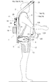
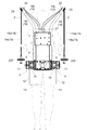
- FIGS. 1, 2, and 3 The overall configuration of the assist device and the main body 1 will be described. As shown in FIGS. 1, 2, and 3, the main body 1 is attached to the operator's back, the right and left arm 2 extending upward from the upper portion of the main body 1, and the lower portion of the main body 1.
- the right and left leg action portions 3 are provided, and an attachment belt 4 for attachment to an operator and right and left shoulder belts 5 are provided to constitute an assist device.
- the main body 1 includes a right and left vertical frame 6, support plates 7 and 8 connected across the upper and middle portions of the right and left vertical frames 6, right and left A horizontal frame 9 and the like connected to the lower part of the left vertical frame 6 are provided and configured in a frame shape.
- An attachment belt 4 is attached to the leg action part 3, and a shoulder belt 5 is attached to the vertical frame 6.
- a control device 14 is connected to the rear surface of the support plate 8, and a battery 16 is attached to the support plate 15 connected to the support plate 8 so as to cover the rear side of the control device 14.
- the operator's back (the shoulder) is placed on the shoulder belt 5 and the attachment belt 4 is wrapped around the waist of the worker and fixed.
- the body part 1 is attached to the part.
- the weight of the assist device and the luggage is mainly applied to the operator's waist through the attachment belt 4, and the weight of the assist device and the luggage depends on the waist of the operator. It is supported stably.
- the right and left shoulder belts 5 mainly exhibit a function of stopping the state in which the main body 1 is about to move backward from the back of the operator.
- the leg action unit 3 includes a base 10, a transmission case 11, an operation arm 12, a leg belt 13, and the like.
- a base 10 is supported by the horizontal frame 9 so as to be slidable in the left-right direction, and a transmission case 11 is connected to the outer end of the base 10 in a forward direction.
- an operation arm 12 is swingably supported around a horizontal axis P ⁇ b> 1 in the left-right direction at the front portion of the transmission case 11, and a wide belt-like leg belt 13 is formed.
- the end of the operation arm 12 is connected.
- a transmission mechanism (not shown) constituted by a plurality of spur gears is provided inside the transmission case 11, and an electric motor (not shown) is built in the left and right direction in the base 10, and the transmission mechanism is provided by the electric motor.
- the operating arm 12 is driven to swing around the horizontal axis P1.
- the right and left The leg action part 3 (base part 10) is movable in the left-right direction along the horizontal frame 9.
- the distance between the right and left leg action portions 3 is determined so as to match the physique of the operator, depending on how the attachment belt 4 is wrapped around the waist, and the right and left leg action portions 3 are determined by the attachment belt 4. The position is determined.
- the operator winds the leg belt 13 around the thigh and uses a hook and loop fastener (not shown) (trade name: Velcro (registered trademark)) to form the leg belt. Attach 13 to the thigh.
- a hook and loop fastener (trade name: Velcro (registered trademark)
- Velcro registered trademark
- the right and left arm portions 2 will be described. As shown in FIGS. 1, 2, and 3, the upper portions of the right and left vertical frames 6 extend diagonally upward on the diagonally front side beyond the right and left shoulders of the operator, and the right and left arms The portion 2 is configured, and a guide pulley 25 is rotatably supported on the upper end portion of the arm portion 2.
- a lifting device 17 is connected to the rear surface of the support plate 7, and the right two wires 18 and 19 and the two left wires 18 and 19 are connected from the lifting device 17.
- the receiving member 21 is connected to the upper part of the support plate 7, the receiving member 22 is connected to the upper part of the arm portion 2, and the outer 18 b and 19 b of the wires 18 and 19 are connected to the receiving members 21 and 22, , 19 are connected to the lifting device 17.
- the inner wires 18a and 19a of the right two wires 18 and 19 are hung on the guide pulley 25 and extended downward, and the right two wires 18 and 19,
- the right hand unit 20 is connected to the 19 inners 18a, 19a.
- Inner portions 18a and 19a of the left two wires 18 and 19 are hung on the guide pulley 25 and extended downward, and the left hand 18 and the inner portions 18a and 19a of the left two wires 18 and 19 are connected to the left hand.
- the unit 20 is connected.
- the elevating device 17 is connected to the support plate 7, and is connected horizontally to a vertically extending transmission case 30 that houses a transmission mechanism (not shown) and a lower portion of the transmission case 30.
- an electric motor 29 a support case 26 connected horizontally to the upper portion of the transmission case 30, and four rotating bodies (not shown) that are rotatable around a horizontal axis inside the support case 26 are provided. .
- the outer 18 b and 19 b of the wires 18 and 19 are connected to the receiving member 21, and the inner 18 a and 19 a of the wires 18 and 19 are the four rotating bodies inside the support case 26. Connected to each.
- the power of the electric motor 29 is transmitted to the rotating body inside the support case 26 via the transmission mechanism inside the transmission case 30, and the rotating body is wound. It is rotationally driven to the take-out side (upward side of the hand part 20) and the feeding side (downward side of the hand part 20).
- the electric motor 29 is provided with an electromagnetic brake (not shown). When the electric motor 29 is operated, the electromagnetic brake is released, and when the electric motor 29 is stopped or not energized, the electromagnetic brake is in a braking state.
- the right and left hand units 20 will be described. 4 to 7, the right hand unit 20 is shown, and the left hand unit 20 has a symmetrical shape with respect to the right hand unit 20.
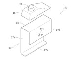
- the hand unit 20 includes a support member 27 formed by bending a metal plate and a cover 28 made of synthetic resin. The cover 28 is attached to the support member 27. ing.
- the cover 28 is provided with a raising operation switch 23 (corresponding to a manual operation unit), and in the left hand unit 20, the lowering operation switch 24 ( Equivalent to a manual operation unit).
- the raising and lowering operation switches 23 and 24 are connected to the control device 14 via a harness (not shown).
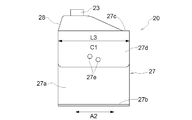
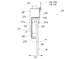
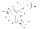
- a vertical wall-shaped lateral side portion 27 a As shown in FIGS. 4 and 5, in the support member 27, a vertical wall-shaped lateral side portion 27 a, a lower side portion 27 b that protrudes laterally from the lower portion of the lateral side portion 27 a, and an upper side of the lateral side portion 27 a And an inner portion 27d protruding downward from the upper portion 27c.
- a cover 28 is attached to the upper portion 27 c of the support member 27, and inner holes 27 d of the wires 18 and 19 are opened in the inner portion 27 d of the support member 27.
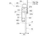
- the lower side protrudes laterally from the lower portion of the lateral side portion 27 a of the support member 27 with respect to the distance L1 in the lateral width direction A1 between the lateral side portion 27 a and the inner side portion 27 d of the support member 27.
- the protrusion length L2 of the part 27b is short.
- connection hole 27e of the support member 27 is provided in the lower portion of the inner portion 27d of the support member 27, and the longitudinal direction A2 (horizontal width) of the support member 27 (inner portion 27d and lower portion 27b). It is located in the central part C1 of the length L3 in the longitudinal direction A2) intersecting the direction A1.
- the lateral side portion 27a and the inner portion 27d of the support member 27 are connected.
- the wires 18 and 19 are connected to a portion closer to the inner portion 27d in the hand portion 20 than the central portion C2 in the horizontal width direction A1 (interval L1) therebetween.
- the operator pushes the up and down operation switches 23 and 24 with the thumbs of the right hand and the left hand.
- the ascending and descending operation switches 23 and 24 are configured to be returnable, and when the operator pushes the ascending and descending operation switches 23 and 24, the operation signals are received from the ascending and descending operation switches 23 and 24.
- the operation signals of the up / down operation switches 23, 24 are stopped.
- the lateral wall portion W1 of the case W is inserted between the lateral side portion 27a and the inner side portion 27d of the support member 27, and the lower side portion 2b of the support member 27 is placed in the case. It is allowed to enter the lower side of the protrusion W3 of W.
- the lateral side portion 27 a of the support member 27 is arranged in the vertical direction along the outside of the lateral wall portion W ⁇ b> 1 of the case W, and the lower side portion 2 b of the support member 27 is supported by the support member 27. It protrudes from the lower portion of the lateral side portion 27a to the lateral wall portion W1 side of the case W, and enters the lower side of the protruding portion W3 of the case W.
- the upper portion 27c of the support member 27 protrudes from the upper portion of the lateral side portion 27a of the support member 27 to the lateral wall portion W1 side of the case W, and is disposed above the protruding portion W2 of the case W.
- the inner portion 27d of the member 27 protrudes downward from the upper portion 27c of the support member 27 and is arranged in the vertical direction along the inner side of the lateral wall portion W1 of the case W.
- the lateral width of the protruding portion W3 of the case W is narrow in the lateral width direction A1.
- it protrudes laterally from the lower part of the lateral side portion 27a of the support member 27 with respect to the distance L1 in the lateral width direction A1 between the lateral side portion 27a and the inner side portion 27d of the support member 27. Since the protruding length L2 of the lower side portion 27b is short, the lower side portion 27b of the support member 27 easily enters the lower side of the protruding portion W3 of the case W.
- the support member 27 when the inner side 27d of the case 27 comes into contact with the inner side of the lateral wall part W1 of the case W, the lower side part 27b of the support member 27 tends to come out from the lower side of the protruding part W3 of the case W (the hand part 20 is The state of being detached from the lateral wall portion W1). This state is the same whether the lateral wall W1 of the case W has an opening or no opening.
- the support member 27 is caused by the moment M1.
- the state in which the lower side portion 27b of 27 is about to come out from the lower side of the protruding portion W3 of the case W is suppressed.
- the electromagnetic brake is released when the electric motor 29 is operated, and the electromagnetic brake is braked when the electric motor 29 is stopped and de-energized. It becomes a state.
- the electric motor 29 is stopped, the inner portions 18a and 19a of the wires 18 and 19 are not drawn out from the lifting device 17, and the weight of the case W is applied to the right and left hand portions 20 as will be described later. However, the right and left hand portions 20 do not descend.
- the operator lifts the case W from the floor by standing up with the right and left hand portions 20 attached to the lateral wall portion W1 of the case W.
- the right and left leg action portions 3 operation arms 12
- the operator's thighs are operated downward.
- the person's standing up is assisted.
- the right and left hand portions 20 (case W) are not lowered by the brake function of the electric motor 29 described above.
- the lifting / lowering device 17 operates to the winding side, the inners 18a and 19a of the wires 18 and 19 are wound, and the right and left hand portions 20 (case W) are raised.
- the lifting device 17 is stopped by stopping the pushing operation of the raising operation switch 23, and the right and left hand portions 20 (case W) are moved. Stop.
- the worker walks to a high shelf on which the case W is to be placed, a truck bed, or the like.
- the lifting device 17 operates to the feeding side, and the inners 18a, 19a of the wires 18, 19 are fed out.
- the right and left hand portions 20 (case W) are lowered.
- the case W is placed on a high shelf, a truck bed, or the like, and the right and left hand portions 20 are removed from the case W.
- the initial state is restored, and the same operation is performed on the next case W.
- the right and left hand units 20 will be described. 8 to 11, the right hand unit 20 is shown, and the left hand unit 20 has a symmetrical shape with respect to the right hand unit 20.
- the hand unit 20 includes a support member 27 formed by bending a metal plate and a cover 28 made of synthetic resin.
- the cover 28 is attached to the support member 27. ing.
- the cover 28 is provided with the raising operation switch 23, and in the left hand unit 20, the cover 28 is provided with the lowering operation switch 24 (see FIGS. 2 and 3).
- the raising and lowering operation switches 23 and 24 are connected to the control device 14 via a harness (not shown).
- the vertical wall-shaped lateral side portion 27a, the lower side portion 27b projecting laterally from the lower portion of the lateral side portion 27a, and the upper portion of the lateral side portion 27a As shown in FIGS. 8 and 9, in the support member 27, the vertical wall-shaped lateral side portion 27a, the lower side portion 27b projecting laterally from the lower portion of the lateral side portion 27a, and the upper portion of the lateral side portion 27a.
- An upper portion 27c that protrudes laterally from the front portion and an inner portion 27d that protrudes downward from the upper portion 27c are provided.
- the lower side protrudes laterally from the lower portion of the lateral side portion 27a of the support member 27 with respect to the distance L1 in the lateral width direction A1 between the lateral side portion 27a and the inner side portion 27d of the support member 27.
- the protrusion length L2 of the part 27b is short.
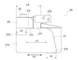
- the inner side of the support member 27 is located on the upper portion 27c of the front support member 27 with respect to the center portion C3 of the length L4 in the longitudinal direction A2 of the upper portion 27c of the support member 27.
- a portion 27d is provided.
- the inner portion 27d of the support member 27 has a length L5 that is shorter than the length L4 of the upper portion 27c of the support member 27 in the longitudinal direction A2.
- the support member 27 is located closer to the lateral side portion 27 a of the support member 27 on the rear side than the center portion C3 of the longitudinal direction A2 length L4 of the upper portion 27 c of the support member 27.
- a lower side portion 27b is provided.
- the lower side portion 27b of the support member 27 has a length L6 that is shorter than the length L4 in the longitudinal direction A2 of the upper side portion 27c of the support member 27.
- L6 is set to a short one. Accordingly, the inner side 27d of the support member 27 (the end on the lower side 27b side of the inner side 27d of the support member 27) and the lower side 27b of the support member 27 (the inner side of the lower side 27b of the support member 27). 27d side end), an interval L7 along the longitudinal direction A2 of the upper portion 27c of the support member 27 is generated.
- connection portion 27 f protrudes upward at the rear portion of the upper portion 27 c of the support member 27 and on the inner portion 27 d side of the support member 27, and the connection portion 27 f has a connection hole. 27e is opened, and the inners 18a and 19a of the wires 18 and 19 are connected to the connection hole 27e. Thereby, the connection part 27f and the connection hole 27e of the support member 27 are located substantially right above the lower part 27b of the support member 27 in a side view (see FIG. 9).
- the inner sides 18 a and 19 a of the wires 18 and 19 are connected to the connection portion 27 f (connection hole 27 e) of the support member 27, whereby the lateral side portion 27 a and the inner portion 27 d of the support member 27 are connected.
- the wires 18 and 19 are connected to a portion closer to the inner portion 27d in the hand portion 20 (support member 27) than the central portion C2 in the width direction A1 (interval L1) therebetween. ing.
- the center portion C3 in the longitudinal direction A2 of the upper portion 27c of the support member 27 intersecting the lateral width direction A1 is closer to one or the other end portion in the longitudinal direction A2 of the upper portion 27c of the support member 27 in the hand portion 20.
- the wires 18 and 19 are connected to the portion.
- the end on the lower side 27b side of the inner side 27d of the support member 27 and the end on the inner side 27d side of the lower side 27b of the support member 27 are connected by a straight line.
- the distance L8 (the diagonal distance L8 between the end on the lower side 27b side of the inner side 27d of the support member 27 and the end on the inner side 27d side of the lower side 27b of the support member 27) is wide. It has become. Accordingly, the posture of the hand unit 20 is set obliquely so that the interval L8 is in a state along the vertical direction, and the hand unit 20 is set to the oblique posture similar to that in FIG. 7 (see the previous item [6]). Thus, the hand portion 20 can be attached to the lateral wall portion W1 of the case W without difficulty.
- the lateral side portion 27 a of the support member 27 is arranged vertically along the outside of the lateral wall portion W ⁇ b> 1 of the case W, and the lower side portion 2 b of the support member 27 is supported by the support member 27. It protrudes from the lower portion of the lateral side portion 27a to the lateral wall portion W1 side of the case W, and enters the lower side of the protruding portion W3 of the case W.
- the upper portion 27c of the support member 27 protrudes from the upper portion of the lateral side portion 27a of the support member 27 toward the lateral wall portion W1 of the case W, and is disposed above the protruding portion W2 of the case W.
- the inner portion 27d of the member 27 protrudes downward from the upper portion 27c of the support member 27 and is arranged in the vertical direction along the inner side of the lateral wall portion W1 of the case W.
- the support member 27 when the inner side 27d of the case 27 comes into contact with the inner side of the lateral wall part W1 of the case W, the lower side part 27b of the support member 27 tends to come out from the lower side of the protruding part W3 of the case W (the hand part 20 is The state of being detached from the lateral wall portion W1). This state is the same whether the lateral wall W1 of the case W has an opening or no opening.
- the support member 27 is caused by the moment M1.
- the state in which the lower side portion 27b of 27 is about to come out from the lower side of the protruding portion W3 of the case W is suppressed.
- the support member 27 is located closer to the upper portion 27 c of the support member 27 on the rear side than the central portion C3 of the length L4 in the longitudinal direction A2 of the upper portion 27 c of the support member 27.
- An inner portion 27d is provided.
- the inner portion 27d of the support member 27 has a length L5 that is shorter than the length L4 of the upper portion 27c of the support member 27 in the longitudinal direction A2.
- the support member 27 is a portion of the upper portion 27 c of the front support member 27 with respect to the center portion C3 of the length L4 in the longitudinal direction A2 of the upper portion 27 c of the support member 27.
- a connecting portion 27f and a connecting hole 27e of the support member 27 are provided on the inner portion 27d side.
- connection portion 27 f connection hole 27 e
- Wires 18 and 19 are closer to the inner part 27d in the hand part 20 (supporting member 27) than the center part C2 (see FIG. 10) in the lateral width direction A1 (interval L1) between them and 27d. ) Is connected.
- the center portion C3 in the longitudinal direction A2 of the upper portion 27c of the support member 27 intersecting the lateral width direction A1 is closer to one or the other end portion in the longitudinal direction A2 of the upper portion 27c of the support member 27 in the hand portion 20.
- the wires 18 and 19 are connected to the portion.
- the lower side of the support member 27 is placed on the side portion 27a of the front support member 27.
- a side portion 27b is provided.
- the lower side portion 27b of the support member 27 has a length L6 that is shorter than the length L4 in the longitudinal direction A2 of the upper side portion 27c of the support member 27.
- connection portion 27 f and the connection hole 27 e of the support member 27, and the inner portion 27 d of the support member 27 in the longitudinal direction A2 of the upper portion 27 c of the support member 27 In this state, the lower portion 27b of the support member 27 is located. In this case, the lower side portion 27b of the support member 27 is provided at a position slightly forward (or slightly rearward) of the central portion C3 of the length L4 in the longitudinal direction A2 of the upper portion 27c of the support member 27. It may be configured.
- the lower portion 27 b of the support member 27 (the front portion of the lower portion 27 b) is pressed upward against the lower surface of the protruding portion W ⁇ b> 3 of the case W, and the upper portion 27 c ( The rear portion of the upper portion 27c is pressed downward against the upper surface of the protruding portion W2 of the case W.
- a frictional force is generated between the lower side portion 27b of the support member 27 (the front portion of the lower side portion 27b) and the lower surface of the protruding portion W3 of the case W, and the upper side portion 27c (upper side portion 27c) of the support member 27 is generated.
- the rear portion) and the upper surface of the protrusion W2 of the case W are in a state where a frictional force is generated.
- the lower side portion 27b of the support member 27 is configured as a separate member with respect to the lateral side portion 27a of the support member 27.
- Two bolts 27 g are connected to the lower side portion 27 b of the support member 27, and a plurality of connection holes 27 h are arranged in the vertical direction on the lateral side portion 27 a of the support member 27.
- the bolt 27 g of the lower side portion 27 b of the support member 27 is inserted into the connection hole 27 h of the lateral side portion 27 a of the support member 27, and the nut 31 is used to The lower side portion 27 b is connected to the lateral side portion 27 a of the support member 27.
- the connection hole 27h into which the bolt 27g of the lower side portion 27b of the support member 27 is inserted, the connection position of the lower side portion 27b in the lateral side portion 27a of the support member 27 can be changed up and down.
- the wires 18 and 19 are connected to the front part or the rear part of the inner part 27d of the support member 27 (the front side or the center part C1 of the length L3 in the longitudinal direction A2). You may comprise so that it may connect to a rear side.
- a moment M2 is generated to rotate the hand portion 20 around the lateral axis that intersects the lateral wall portion W1 of the case W (see FIG. 13).
- the wires 18 and 19 are connected to the portion on the inner side 27d side of the support member 27 in the upper side portion 27c of the support member 27 rather than the central portion C2. Also good.
- the center portion C1 of the length L3 in the longitudinal direction A2 of the support member 27 (the inner portion 27d and the lower portion 27b) the position in front of the center portion C1, the center portion C1. What is necessary is just to connect the wires 18 and 19 (inner 18a, 19a) to the position of the back rather than.
- the lower portion 27b is provided at the front portion of the lower portion of the lateral side portion 27a of the support member 27, and the upper portion is disposed at the rear portion of the upper portion of the lateral side portion 27a of the support member 27.
- the support member 27 in the portion of the upper portion 27c of the support member 27 on the front side of the center portion C3 of the length L4 in the longitudinal direction A2 of the upper portion 27c of the support member 27, includes an inner portion 27d, and is a portion of the upper portion 27c of the support member 27 on the rear side of the central portion C3 of the length L4 in the longitudinal direction A2 of the upper portion 27c of the support member 27, and the support member 27 may be provided with a connection portion 27f and a connection hole 27e of the support member 27 on the inner side portion 27d side.
- the lower portion 27b and the inner portion 27d of the support member 27 are formed in a quadrangular shape in plan view (side view). Instead of configuring, it may be configured in a semicircular shape or a trapezoidal shape.
- the lower side portion 27b and the inner side portion 27d of the support member 27 are completely separated along the longitudinal direction A2 of the upper side portion 27c of the support member 27 as shown in FIGS. Instead, a part of the base of the lower part 27b of the support member 27 (the part connected to the lateral part 27a of the support member 27) and the base of the inner part 27d of the support member 27 (the lateral side of the support member 27)
- the lower portion 27b and the inner portion 27d of the support member 27 may be separated so that a part of the portion connected to the portion 27a overlaps in plan view.
- the ascending operation switch 23 may be provided in the left hand unit 20 and the descending operation switch 24 may be provided in the right hand unit 20. Both the ascending and descending operation switches 23 and 24 may be provided in the right (left) hand unit 20.
- the right hand unit 20 shown in FIGS. 1, 2, and 3 may be provided with one wire 18, and the left hand unit 20 may be provided with one wire 18.
- the right and left arm portions 2 may be eliminated and one arm portion 2 may be provided.
- the two wires 18 are extended from one arm portion 2, the right hand portion 20 is provided on one of the two wires 18, and the left hand is placed on the other of the two wires 18.
- a hand unit 20 is provided.
- one wire 18 is extended from one arm portion 2, the end of one wire 18 is bifurcated, and a right hand portion 20 is provided on one of the branch portions.
- the left hand unit 20 is provided on the other side.
- the right and left hand portions 20 are provided.
- the right and left hand portions 20 can be attached to the case W by allowing the lower portion 27b of the support member 27 to enter the recesses of the lateral wall portion W1 of the case W.
- FIG. 14, FIG. 15 and FIG. 16 show an assist device including the hand unit 120 of the second embodiment. 17 and 18, the right hand unit 120 is shown, and the left hand unit 120 has a symmetrical shape with respect to the right hand unit 120.
- the right and left hand portions 120 are made of cloth gloves.
- the right and left hand portions 120 (gloves) are provided with a main body portion 127 into which an operator's palm (back of the hand) enters, and a belt-like (loop-like) connection portion 128 is provided at a portion of the main body portion 127 on the back side of the hand. It has been.
- the ends of the inners 18 a and 19 a of the right (left) wires 18 and 19 are passed through the connection part 128 of the right (left) hand part 120 (gloves), It is connected to the upper part of the inners 18a, 19a of the right (left) wires 18, 19 by a fixing bracket 138 (at the end of the inners 18a, 19a of the right (left) wires 18, 19 by the fixing bracket 138).
- a loop portion is formed, and the connection portion 128 of the right (left) hand portion 120 (gloves) is passed through the loop portion).
- the inner portions 18a and 19a of the right wires 18 and 19 are connected to the connecting portion 128 of the right hand portion 120 (gloves), and the left hand portion 120 (gloves) is connected to the left connecting portion 128 of the left hand portion 120 (gloves). Inners 18a and 19a of the wires 18 and 19 are connected.
- the right and left hand parts 120 are connected to the main body part 127 and are connected to the first finger part 131 into which the operator's thumb enters and the main body part 127.
- the second finger part 132 into which the operator's index finger enters, the third finger part 133 into which the operator's middle finger enters and the one connected to the main body part 127, and the ring finger of the operator into the body part 127.
- a fifth finger part 135 is provided which is connected to the fourth finger part 134 and the main body part 127 and into which an operator's little finger enters.
- the second finger portion 132 (corresponding to a specific finger portion of the right and left gloves) holds all the index fingers of the operator. It is configured to cover a bag.
- a rising operation switch 123 (corresponding to a manual operation unit) is provided in the second finger unit 132
- a lowering operation switch is provided in the second finger unit 132.
- 124 (corresponding to a manual operation unit) (see FIGS. 15 and 16).
- the raising and lowering operation switches 123 and 124 are connected to the control device 14 via a harness (not shown). In this case, the raising operation switch 123 (the lowering operation switch 124 (see FIGS. 15 and 16)) can be provided on the outside (outer surface) of the second finger portion 132.
- the first, third, fourth and fifth finger portions 131, 133, 134 and 135 are configured in a cylindrical shape instead of a bag shape, and is provided with openings 131a, 133a, 134a, 135a on the fingertip side.
- a synthetic rubber non-slip portion 136 is affixed to the palm portion of the main body 127 and the ventral side (palm side) of the first to fifth fingers 131 to 135.
- the index finger is covered with the second finger portion 132, and the thumb and middle fingers
- the fingertips of the ring finger and little finger are exposed from the openings 131a, 133a, 134a, and 135a of the first, third, fourth, and fifth finger portions 131, 133, 134, and 135.
- an operator wears right and left hand parts 120 (gloves) on the right hand and left hand, and the right hand (hand part 120) (gloves) and left hand (hand part 120) (gloves). ), The operator pushes the lifting operation switch 123 against the luggage with the right index finger, and pushes the lowering operation switch 124 against the luggage with the left index finger. Manipulate.
- the ascending and descending operation switches 123 and 124 are configured to be a pressure-sensitive type and a return type.
- an operation signal is output from the ascending / descending operation switches 123, 124, and the operator pushes the ascending / descending operation switches 123, 124.
- the operation signals of the up and down operation switches 123 and 124 are stopped.
- the electromagnetic brake is released when the electric motor 29 is operated, and the electromagnetic brake is braked when the electric motor 29 is stopped and de-energized. It becomes a state.
- the inners 18a and 19a of the wires 18 and 19 are not drawn out from the lifting device 17, and as will be described later, the right hand (hand part 120) (gloves) and the left hand (hand part) 120) Even if the weight of the load is applied to the (gloves), the right hand (hand part 120) (gloves) and the left hand (hand part 120) (gloves) do not descend.
- the operator holds the load with the right hand (hand unit 120) (gloves) and the left hand (hand unit 120) (gloves), and lifts the load from the floor by standing up.
- the operator pushes the raising operation switch 123, the right and left leg action portions 3 (operation arms 12) are driven downward, and the operator's thigh is operated downward, The person's standing up is assisted.
- the right hand (hand unit 120) (gloves) and the left hand (hand unit 120) (gloves) are not lowered by the brake function of the electric motor 129 described above.
- the lifting / lowering device 17 is operated to the winding side so that the inners 18a and 19a of the wires 18 and 19 are wound up, and the right hand (hand part 120) (gloves) and the left hand (hand part 120) (gloves) are opened.
- the lifting device 17 is stopped by stopping the pushing operation of the raising operation switch 123, and the right hand (hand unit). 120) (gloves) and the left hand (hand part 120) (gloves) stop.
- the worker walks to a high shelf or a truck bed where the luggage should be placed.
- the lifting device 17 operates to the feeding side, and the inners 18a and 19a of the wires 18 and 19 are fed out.
- the right hand (hand part 120) (gloves) and the left hand (hand part 20) (gloves) are lowered.
- the luggage is placed on a high shelf, a truck bed or the like, and the right hand (hand part 120) (gloves) and the left hand (hand part 120) (gloves) are separated from the luggage.
- the initial state is restored, and the same operation is performed on the next luggage.
- the right and left hand portions 120 (gloves) of the above (second embodiment) may be configured as shown in FIG.
- the second finger portion 132 is formed in a cylindrical shape instead of a bag shape (the opening portion 132a is provided on the fingertip side), and the raising operation switch 123 is provided.
- a fingertip portion 137 (corresponding to a specific finger portion) provided with a (lowering operation switch 124) is used as a separate member, and a second finger is formed by a hook-and-loop fastener (not shown) (trade name: Velcro (registered trademark)).
- the opening 132a of the part 132 is configured to be detachable. In this case, you may comprise so that the raising operation switch 123 (falling operation switch 124) may be provided in the exterior (outer surface) of the fingertip part 137.
- the state shown in FIG. 19 is a state in which the fingertip portion 137 is attached to the second finger portion 132 in the right and left hand portions 120 (gloves).
- the fingertip part 137 is changed to the opening part 131a of the first finger part 131 or the opening part 133a of the third finger part 133.
- it can attach to the opening part 134a of the 4th finger part 134, or the opening part 135a of the 5th finger part 135 with a hook-and-loop fastener (not shown) (brand name: Velcro (registered trademark)).
- the right and left hand portions 120 (gloves) of the above-described (second embodiment) may be configured as shown in FIG.
- the second finger portion 132 is formed in a cylindrical shape instead of a bag shape (the opening portion 132a is provided on the fingertip side).
- a cloth string portion 139 is connected to and extended from an edge portion of the opening 132 a of the second finger portion 132, and a cloth ring portion 140 is connected to the string portion 139.
- a rising operation switch 123 is provided on the inner surface (or outer surface) of the ring unit 140 of the second finger unit 132, and the left hand unit 120 (gloves).
- a lower operation switch 124 is provided on the inner surface (or outer surface) of the ring part 140 of the second finger part 132 (a manual operation part for raising is provided on the finger part of one of the right and left gloves, This corresponds to a state in which the lower and right glove fingers are provided with a manual operation unit for lowering).
- the string part 139 (ring part 40) is connected to the first finger part 131, the third finger part 133, the fourth finger part 134, or the fifth finger part 135 instead of the second finger part 132. You may comprise.
- the string part 139 (ring part 140) is configured to be detachable from the second finger part 132 in the same manner as the above-mentioned [first alternative form of the second embodiment], and the removed string part 139 (ring part) 140) may be configured to be attachable to and detachable from the first finger 131, the third finger 133, the fourth finger 134, or the fifth finger 135.
- the second finger portion 132 is not configured in a bag shape, but the first finger portion 131, the third finger portion 133, or The fourth finger part 134 or the fifth finger part 135 is formed in a bag shape, and the ascending operation switch 123 (the descending operation switch is provided on one of the first, third, fourth, and fifth finger parts 131, 133, 134, and 135. 124).
- one of the first to fifth finger portions 131 to 135 having a cylindrical shape having openings 131a to 135a is provided with a fingertip portion 137 having a lifting operation switch 123 (lowering operation switch 124) (string A portion 139 (ring portion 140) may be attached.
- the ascending operation switch 123 may be provided in the left hand unit 120 (gloves), and the descending operation switch 124 may be provided in the right hand unit 120 (gloves).
- the right hand unit 120 includes one wire 18, and the left hand unit 120 (gloves) includes one wire 18. May be.
- the right and left arm portions 2 may be eliminated and one arm portion 2 may be provided.
- the two wires 18 are extended from one arm portion 2, and the right hand portion 120 (gloves) is provided on one of the two wires 18, and the other of the two wires 18 is provided.
- the left hand part 120 (gloves) is provided.
- one wire 18 is extended from one arm portion 2 and the end of one wire 18 is bifurcated, and a right hand portion 120 (gloves) is provided on one of the branch portions, A left hand portion 120 (gloves) is provided on the other of the branch portions.
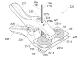
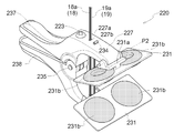
- the hand unit 220 is provided with a first holding arm 227 and a second holding arm 228.
- the first and second holding arms 227 and 228 are swingably connected to each other via a fulcrum pin 235, and the first and second holding arms 227 and 228 approach and separate from each other around the fulcrum pin 235.
- the operation arms 237 and 238 extend from the first and second holding arms 227 and 228 in the direction opposite to the extending direction of the first and second holding arms 227 and 228, respectively.
- a spring 236 that urges the operation arms 237 and 238 in a direction to separate them from each other (a direction in which the first and second holding arms 227 and 228 approach each other) is attached to the fulcrum pin 235 and the operation arms 237 and 238.
- the 1st and 2nd holding arms 227 and 228 (operation arms 237 and 238) are in a state like a clothespin.
- end portions of the first and second holding arms 227 and 228 are provided with holding portions 231 whose posture can be changed within a predetermined range.
- the holding part 231 is formed in a flat plate shape, and the bracket 231a and the pair of rubber bodies 231b are connected to each other.
- the holding portion 231 is supported by the bracket 231a of the holding portion 231 so as to freely swing around the axis P2 at the ends of the first and second holding arms 227 and 228.
- the first holding arm 227 is opened with an opening 227 a (corresponding to the first guide portion) (corresponding to the operating means) and an opening 227 b (corresponding to the operating means). Yes. Openings 228 a and 228 b are opened in the second holding arm 228.
- a U-shaped bracket 232 is connected to the openings 228a and 228b of the second holding arm 228, and a roller 233 (corresponding to the second guide portion) around the axis P3 of the bracket 232 (corresponding to the operating means) ) Is rotatably supported.
- the inners 18 a and 19 a of the wires 18 and 19 extend through the opening 227 a of the first holding arm 227 toward the second holding arm 228 (first The inner portion 18a, 19a of the wire 18, 19 is guided toward the second holding arm 228 while movement along the longitudinal direction of the inner portion 18a, 19a of the wire 18, 19 is allowed by the opening 227a of the first holding arm 227.
- the inners 18 a and 19 a of the wires 18 and 19 pass through the opening 228 a of the second holding arm 228, are wound around the roller 233, and pass through the opening 228 b of the second holding arm 228. And extends toward the first holding arm 227 (while the roller 233 of the second holding arm 228 allows movement along the longitudinal direction of the inners 18a, 19a of the wires 18, 19 while the wire 18 , 19 corresponds to a state in which the inners 18a, 19a are guided toward the first holding arm 227).
- the inners 18 a and 19 a of the wires 18 and 19 pass through the opening 228 b from the roller 233 of the second holding arm 228 and face the first holding arm 227, so that the first holding is performed. It passes through the opening 227b of the arm 227.
- a retaining member 234 (corresponding to an operating means) is attached to the ends of the inners 18a and 19a of the wires 18 and 19, and the inners 18a and 19a of the wires 18 and 19 come out of the opening 227b of the first holding arm 227. There is no state (a state connected to the first holding arm 27). As described above, the opening 227a and 227b of the first holding arm 27, the roller 233 of the second holding arm 228, the retaining member 234, and the like constitute the operating means.
- the first holding arm 227 is provided with a raising operation switch 223 (corresponding to a manual operation unit). As shown in FIG. 27, in the left hand unit 220, the first holding arm 227 is provided with a lowering operation switch 224 (corresponding to a manual operation unit).
- the raising and lowering operation switches 223 and 224 are connected to the control device 14 via a harness (not shown).
- the worker in a state where the worker wears the assist device, the worker has the right hand unit 220 with the right hand and the left hand unit 220 with the left hand.
- the ascending and descending operation switches 223 and 224 are pushed by the thumbs of the right hand and the left hand.
- the ascending / descending operation switches 223 and 224 are configured to return, and when the operator pushes the ascending / descending operation switches 223 and 224, operation signals from the ascending and descending operation switches 223 and 224 are displayed.
- the operation signals of the up / down operation switches 223, 224 are stopped.
- the first and second holding arms 227 and 228 are separated from each other by gripping the operating arms 237 and 238 so that the right and left hand portions 220 approach each other. 26 and 27, the first and second holding arms 227 and 228 hold the bag W so that one (the other) edge W1 is sandwiched therebetween.
- the urging force of the spring 236 shown in FIG. 25 holds the first and second holding arms 227 and 228 of the hand portion 220 so as to sandwich the edge portion W1 of the bag W.
- the bag W is held by the holding portion 231 without difficulty between the first and second holding arms 227, 228 of the hand portion 220.
- the first holding arm 227 of the hand unit 220 is extended upward from the opening 227 a of the first holding arm 227 to the inner portions 18 a and 19 a of the wires 18 and 19.
- the first holding arm 227 is located on the upper side
- the second holding arm 228 is located on the lower side
- the hand unit 220 is directed obliquely downward.
- the raising and lowering operation switches 223 and 224 are in a state of being positioned on the upper side.
- the first and second holding arms 227, 228 are changed from the inner portions 18a, 19a of the wires 18, 19 to the first and second holding arms 227, 228. Therefore, the edge W1 of the bag W is strongly held between the first and second holding arms 227 and 228 (holding portion 231).
- the first and second holding arms 227, 228 are moved from the inner portions 18a, 19a of the wires 18, 19 to the first and second holding arms 227, 228.
- the posture of the holding portion 231 changes around the axis P2 according to the shape of the edge W1 of the bag W, whereby the first and second holding arms 227, 228 are obtained.
- the bag W is easily held by the holding portion 231.
- the electromagnetic brake is released when the electric motor 29 is operated, and the electromagnetic brake is braked when the electric motor 29 is stopped and de-energized. It becomes a state.
- the electric motor 29 is stopped, the inner portions 18a and 19a of the wires 18 and 19 are not drawn out from the lifting device 17, and the weight of the bag W is applied to the right and left hand portions 20 as will be described later. Even so, the right and left hand portions 220 do not descend.
- the worker holds the right (left) hand portion 220 with the right hand (left hand), holds the bag W by the right and left hand portions 220, and lifts the bag W from the floor when the worker stands up.
- the operator pushes the raising operation switch 223, the right and left leg action portions 3 (operation arms 12) are driven downward, and the operator's thighs are operated downward.
- the person's standing up is assisted.
- the right and left hand portions 220 (bags W) are not lowered by the brake function of the electric motor 29 described above.
- the lifting / lowering device 17 operates to the winding side, the inners 18a and 19a of the wires 18 and 19 are wound, and the right and left hand portions 220 (bags W) are raised.
- the lifting operation switch 17 is stopped by stopping the pushing operation of the raising operation switch 223, and the right and left hand parts 220 (bags W) are moved. Stop.
- the worker walks to a high shelf on which bags W should be placed or a truck bed.
- the lifting device 17 is operated to the feeding side, and the inners 18a, 19a of the wires 18, 19 are fed out.
- the right and left hand portions 220 are lowered.
- the bag W is placed on a high shelf, a truck bed or the like, and the first and second holding arms 227, 227, 238 are operated by gripping the right and left hand portions 220 so that the operation arms 237, 238 are brought close to each other.
- the right and left hand portions 220 are removed from the bag W by separating the 228.
- the initial state is restored, and the same operation is performed on the next bag W.
- the hand unit 220 may be configured as shown in FIGS.
- the first and second holding arms 227 and 228 are formed by bending a round pipe, and the holding portion 231 is connected to the lower part of the first and second holding arms 227 and 228. (The posture of the holding portion 231 does not change).
- a bracket 239 is coupled to an upper portion of the first holding arm 227, and the first holding arm 227 (bracket 239) and the second holding arm 228 are connected to each other through a fulcrum pin 235 so as to be swingable.
- the first and second holding arms 227 and 228 are moved toward and away from each other around the fulcrum pin 235.
- the operation arm 238 extends from the second holding arm 228 toward the upper side of the first holding arm 227, and the operation arm 237 shown in FIGS.
- the 1 holding arm 227 is not provided. Accordingly, the first and second holding arms 227 and 228 can be separated by performing a grip operation so that the upper portion of the first holding arm 227 and the operation arm 238 are brought close to each other.
- a bracket 241 is connected to the second holding arm 228, and a spring receiving portion 239a is connected to the lower portion of the bracket 239.
- a spring 236 is attached across the fulcrum pin 235, the spring receiving portion 239a of the bracket 239, and the bracket 241, and the first and second holding arms 227 and 228 are urged by the spring 236 in a direction approaching each other.
- a roller 240 (corresponding to the first guide portion) (corresponding to the operation means) is rotatably supported by the bracket 241. 233 is rotatably supported.
- the bracket 242 is connected to the second holding arm 228.
- the second holding arm 228 (bracket 242) is provided with a raising operation switch 223, and in the left hand part 220, the second holding arm 228 (bracket 242) is provided with a lowering operation switch 224. Yes.
- the inners 18 a and 19 a of the wires 18 and 19 are wound around the roller 40 to change the direction and extend toward the second holding arm 228.
- Inners 18 a and 19 a of the wires 18 and 19 are wound around the roller 233 and extend from the second holding arm 228 toward the first holding arm 227.
- a bracket 243 is coupled to the first holding arm 227, and the inners 18a and 19a of the wires 18 and 19 are connected to the first holding arm 227 (bracket 243).
- the bag W is held between the first and second holding arms 227 and 228 so that the first and second holding arms 227 are held. , 228 holds the bag W.
- the hand unit 220 may be configured as shown in FIGS. 31 to 35.
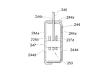
- a box-shaped (square tube-shaped) support portion 244 is configured by bending and connecting two sets of plate members, and extends over the vertical wall portion 244 a of the support portion 244.
- a fulcrum shaft 245 is connected.
- first and second holding arms 227 and 228 are made of a plate material, and a holding portion 231 is connected to the lower part of the first and second holding arms 227 and 228 ( The posture of the holding portion 231 does not change).
- boss portions 227c and 228c connected to the first and second holding arms 227 and 228 are rotatably supported by the fulcrum shaft 245.
- the first and second holding arms 227 and 228 are swingably supported by the support portion 244, and the first and second holding arms 227 and 228 are swung so as to approach and separate from each other. Move.
- arm-like operation portions 227d and 228d are connected to the boss portions 227c and 228c of the first and second holding arms 227 and 228, and the operation portions 227d and 228d are long. Holes 227e and 228e are opened.
- a spring 248 that biases the first and second holding arms 227 and 228 in the approaching direction is attached to the boss portions 227c and 228c and the operation portions 227d and 228d of the first and second holding arms 227 and 228.
- an opening 244 c is provided in the upper wall portion 244 b of the support portion 244, and a plate-like linkage member 246 is inserted into the opening portion 244 c of the support portion 244 so as to be movable up and down.
- a pin-like linking member 247 is connected to the lower part of the linking member 246, and the inners 18 a and 19 a of the wires 18 and 19 are connected to the upper part of the linking member 246.
- a vertical hole 244 d (corresponding to an approach side positioning portion and a separation side positioning portion) is opened in the vertical wall portion 244 a of the support portion 244.
- the linkage member 247 is inserted (connected) into the elongated holes 227e and 228e (operation portions 227d and 228d) of the first and second holding arms 227 and 228, and the linkage member 247 is also inserted into the elongated hole 244d of the support portion 244. Has been inserted.
- the linkage member 247 is inserted into the long holes 227 e and 228 e (operation portions 227 d and 228 d) of the first and second holding arms 227 and 228.
- the two holding arms 227 and 228 are linked to each other, and the first and second holding arms 227 and 228 are similarly operated on the approach side and similarly operated on the separation side.
- the operation means 250 is configured by the wires 18 and 19 (inners 18a and 19a), the linkage members 246 and 247, the operation portions 227d and 228d of the first and second holding arms 227, and the like.
- a fixed handle portion 249 is connected to the upper wall portion 244b of the support portion 244, and the handle portion 249 extends laterally toward the first holding arm 227 side. .
- the upper wall part 244 b of the support part 244 is provided with the raising operation switch 223, and in the left hand part 220, the upper wall part 244 b of the support part 244 is provided with the lowering operation switch 224. Yes.
- the state shown in FIG. 31 is a state in which the bag W is not held in the hand unit 220, and the first and second holding arms 227 and 228 are operated to the approach side by the spring 248.
- the first and second holding arms 227 and 228 are operated to the approach side, they are linked by the operation portions 227d and 228d of the first and second holding arms 227 and 228.
- the member 247 is raised, and the operation of the approaching side of the first and second holding arms 227 and 228 is stopped when the linkage member 247 hits the upper end portion of the long hole 244d of the support portion 244 (first and second). This corresponds to a state where the limit position on the approaching side of the holding arms 227 and 228 is determined on the approaching side).
- the operator can move the right and left hand portions 220 by holding the handle portion 249, and the ascending operation switch with the right hand (left hand) having the handle portion 249. 223 (lowering operation switch 224) can be operated.
- the operator When holding the bag W by the right and left hand portions 220, the operator holds the first holding arm 227 while holding the handle portion 249 so that the first holding arm 227 approaches the handle portion 249.
- the handle portion 249 and the first holding arm 227 are gripped and operated. Accordingly, the first holding arm 227 is operated to the separation side, and the second holding arm 228 is also operated to the separation side by the action of the linkage member 247.
- the first and second holding arms 227 and 228 By operating the first and second holding arms 227 and 228 to the separated side as described above, the first and second holding arms 227 and 228 are operated in the right and left hand portions 220 as shown in FIG. The bag W is held between the first and second holding arms 227 and 228 so that the bag W is held between them.
- the linkage member 247 is positioned at the upper and lower intermediate positions of the long hole 244d of the support portion 244.
- the linkage members 246 and 247 are raised with respect to the support portion 244 (linkage).
- the support portion 244 descends with respect to the members 246 and 247.
- the linkage member 247 causes the operating force to be applied to the first and second holding arms 227 and 228 by moving the first and second holding arms 227 and 228 closer to each other.
- the bag W is strongly held between the first and second holding arms 227 and 228.
- the linkage member 247 hits the upper end of the long hole 244d of the support portion 244, the operation on the approach side of the first and second holding arms 227, 228 is stopped (first and second). This corresponds to a state where the limit position on the approaching side of the holding arms 227 and 228 is determined on the approaching side).
- the second holding arm 228 is connected and fixed to the support portion 244 so as not to swing, and the inner portions 18a and 19a of the wires 18 and 19 are connected to the operation portion 227d of the first holding arm 227. Connect to.
- the ascending operation switch 223 may be provided in the left hand unit 220, and the descending operation switch 224 may be provided in the right hand unit 220. Both the raising and lowering operation switches 223 and 224 may be provided in the right (left) hand unit 220.
- 21 may be configured such that one wire 18 is provided for the right hand unit 220 shown in FIGS. 21, 22, and 23 and one wire 18 is provided for the left hand unit 220.
- the right and left arm portions 2 may be eliminated and one arm portion 2 may be provided.
- the two wires 18 are extended from one arm portion 2, the right hand portion 220 is provided on one of the two wires 18, and the left hand is placed on the other of the two wires 18.
- a hand unit 220 is provided.
- one wire 18 is extended from one arm portion 2 and the end of one wire 18 is bifurcated, and a right hand portion 220 is provided on one of the branch portions.
- the left hand unit 220 is provided on the other side.
- the approach side positioning part (separation side positioning part that determines the limit position on the separation side) that determines the limit position on the approach side of the first and second holding arms 227 and 228 in the above-mentioned [second modification of the third embodiment].
Landscapes
- Engineering & Computer Science (AREA)
- Mechanical Engineering (AREA)
- Life Sciences & Earth Sciences (AREA)
- Geology (AREA)
- Structural Engineering (AREA)
- Robotics (AREA)
- Manipulator (AREA)
Abstract
L'invention concerne un outil d'assistance dont l'utilisation consiste à être ajusté sur un employé et qui comprend une partie main qui peut tenir de manière appropriée une charge même lorsqu'aucune ouverture n'est ménagée dans une partie de paroi latérale de la charge. La partie main (20) est pourvue : d'une partie côté latéral (27a) destinée à être placée dans la direction verticale le long d'un côté externe d'une partie de paroi latérale d'une charge ; d'une partie côté inférieur (27b) qui fait saillie du côté inférieur de la partie côté latéral (27a) vers le côté partie de paroi latérale de la charge de façon à être ajustée dans la partie paroi latérale de la charge ; d'une partie côté supérieur (27c) qui fait saillie du côté supérieur de la partie côté latéral (27a) vers le côté partie de paroi latérale de la charge de manière à être placée sur un côté supérieur de la partie de paroi latérale de la charge ; d'une partie côté interne (27d) qui fait saillie de la partie côté supérieur (27c) vers le côté inférieur et qui est destinée à être placée dans la direction verticale le long d'un côté interne de la partie de paroi latérale de la charge.
Applications Claiming Priority (6)
| Application Number | Priority Date | Filing Date | Title |
|---|---|---|---|
| JP2016-127968 | 2016-06-28 | ||
| JP2016-127967 | 2016-06-28 | ||
| JP2016127967A JP6657036B2 (ja) | 2016-06-28 | 2016-06-28 | アシスト器具 |
| JP2016127966A JP6660827B2 (ja) | 2016-06-28 | 2016-06-28 | アシスト器具 |
| JP2016127968A JP6656096B2 (ja) | 2016-06-28 | 2016-06-28 | アシスト器具 |
| JP2016-127966 | 2016-06-28 |
Publications (1)
| Publication Number | Publication Date |
|---|---|
| WO2018003868A1 true WO2018003868A1 (fr) | 2018-01-04 |
Family
ID=60786401
Family Applications (1)
| Application Number | Title | Priority Date | Filing Date |
|---|---|---|---|
| PCT/JP2017/023773 Ceased WO2018003868A1 (fr) | 2016-06-28 | 2017-06-28 | Outil d'assistance |
Country Status (1)
| Country | Link |
|---|---|
| WO (1) | WO2018003868A1 (fr) |
Cited By (1)
| Publication number | Priority date | Publication date | Assignee | Title |
|---|---|---|---|---|
| JP2020019128A (ja) * | 2018-08-03 | 2020-02-06 | 学校法人 中央大学 | 筋力補助装置及び操作装置 |
Citations (11)
| Publication number | Priority date | Publication date | Assignee | Title |
|---|---|---|---|---|
| JPS49118148A (fr) * | 1973-03-16 | 1974-11-12 | ||
| JPH03127700U (fr) * | 1990-04-03 | 1991-12-24 | ||
| JPH047585U (fr) * | 1990-05-10 | 1992-01-23 | ||
| JPH053284U (ja) * | 1991-07-03 | 1993-01-19 | 荒井建設合資会社 | 蛇籠搬送用把持器 |
| JP3027562U (ja) * | 1995-10-12 | 1996-08-13 | 藤井電工株式会社 | 部品箱吊り上げ用治具 |
| JPH09290988A (ja) * | 1996-04-26 | 1997-11-11 | Hitachi Building Syst Co Ltd | スカートガード取外し工具 |
| JP2005001870A (ja) * | 2003-06-16 | 2005-01-06 | Aikoku Alpha Corp | 荷役物運搬機 |
| JP2008184710A (ja) * | 2007-01-30 | 2008-08-14 | Aikoku Alpha Corp | 荷役物運搬機用グローブ、荷役物運搬機用グローブユニット及び荷役物運搬機 |
| JP2012239818A (ja) * | 2011-05-24 | 2012-12-10 | Tokyo Univ Of Science | 上腕保持装置、及び、上腕補助装置 |
| JP2013052192A (ja) * | 2011-09-06 | 2013-03-21 | Wakayama Univ | パワーアシストロボット装置およびその制御方法 |
| JP2015182832A (ja) * | 2014-03-20 | 2015-10-22 | 株式会社クボタ | アシストスーツ |
-
2017
- 2017-06-28 WO PCT/JP2017/023773 patent/WO2018003868A1/fr not_active Ceased
Patent Citations (11)
| Publication number | Priority date | Publication date | Assignee | Title |
|---|---|---|---|---|
| JPS49118148A (fr) * | 1973-03-16 | 1974-11-12 | ||
| JPH03127700U (fr) * | 1990-04-03 | 1991-12-24 | ||
| JPH047585U (fr) * | 1990-05-10 | 1992-01-23 | ||
| JPH053284U (ja) * | 1991-07-03 | 1993-01-19 | 荒井建設合資会社 | 蛇籠搬送用把持器 |
| JP3027562U (ja) * | 1995-10-12 | 1996-08-13 | 藤井電工株式会社 | 部品箱吊り上げ用治具 |
| JPH09290988A (ja) * | 1996-04-26 | 1997-11-11 | Hitachi Building Syst Co Ltd | スカートガード取外し工具 |
| JP2005001870A (ja) * | 2003-06-16 | 2005-01-06 | Aikoku Alpha Corp | 荷役物運搬機 |
| JP2008184710A (ja) * | 2007-01-30 | 2008-08-14 | Aikoku Alpha Corp | 荷役物運搬機用グローブ、荷役物運搬機用グローブユニット及び荷役物運搬機 |
| JP2012239818A (ja) * | 2011-05-24 | 2012-12-10 | Tokyo Univ Of Science | 上腕保持装置、及び、上腕補助装置 |
| JP2013052192A (ja) * | 2011-09-06 | 2013-03-21 | Wakayama Univ | パワーアシストロボット装置およびその制御方法 |
| JP2015182832A (ja) * | 2014-03-20 | 2015-10-22 | 株式会社クボタ | アシストスーツ |
Cited By (1)
| Publication number | Priority date | Publication date | Assignee | Title |
|---|---|---|---|---|
| JP2020019128A (ja) * | 2018-08-03 | 2020-02-06 | 学校法人 中央大学 | 筋力補助装置及び操作装置 |
Similar Documents
| Publication | Publication Date | Title |
|---|---|---|
| JP6289955B2 (ja) | アシストスーツ | |
| JP6153881B2 (ja) | アシストスーツ | |
| JP6657036B2 (ja) | アシスト器具 | |
| JP6656096B2 (ja) | アシスト器具 | |
| JP2018002342A (ja) | アシスト器具 | |
| JP6616252B2 (ja) | アシスト器具 | |
| WO2018003868A1 (fr) | Outil d'assistance | |
| JP7117952B2 (ja) | 荷物保持用のハンド部 | |
| JP6905842B2 (ja) | 荷物保持用のハンド部 | |
| JP6840044B2 (ja) | 荷物保持用のハンド部 | |
| JP6834038B2 (ja) | アシスト器具 | |
| JP6899677B2 (ja) | 荷物保持用のハンド部 | |
| JP6833665B2 (ja) | アシスト器具 | |
| CN110740967A (zh) | 货物保持用的手部以及协助器具 | |
| JP2019026470A (ja) | アシスト器具 | |
| JP6624940B2 (ja) | アシスト器具 | |
| JP6833664B2 (ja) | アシスト器具又は荷物保持用のハンド部 | |
| JP6854732B2 (ja) | 荷物保持用のハンド部 | |
| JP7061958B2 (ja) | アシスト器具 | |
| JP6745749B2 (ja) | 荷物保持用のハンド部 | |
| JP6758255B2 (ja) | 荷物保持用のハンド部 | |
| JP2020073413A5 (fr) | ||
| WO2019026496A1 (fr) | Élément de préhension pour retenir des bagages, et appareil d'assistance | |
| JP6833663B2 (ja) | アシスト器具又は荷物保持用のハンド部 | |
| JP2018158790A (ja) | 荷物保持用のハンド部 |
Legal Events
| Date | Code | Title | Description |
|---|---|---|---|
| 121 | Ep: the epo has been informed by wipo that ep was designated in this application |
Ref document number: 17820222 Country of ref document: EP Kind code of ref document: A1 |
|
| NENP | Non-entry into the national phase |
Ref country code: DE |
|
| 122 | Ep: pct application non-entry in european phase |
Ref document number: 17820222 Country of ref document: EP Kind code of ref document: A1 |