WO2018003873A1 - Plaquette de coupe - Google Patents
Plaquette de coupe Download PDFInfo
- Publication number
- WO2018003873A1 WO2018003873A1 PCT/JP2017/023789 JP2017023789W WO2018003873A1 WO 2018003873 A1 WO2018003873 A1 WO 2018003873A1 JP 2017023789 W JP2017023789 W JP 2017023789W WO 2018003873 A1 WO2018003873 A1 WO 2018003873A1
- Authority
- WO
- WIPO (PCT)
- Prior art keywords
- blade
- corner
- wiper blade
- honing
- flank
- Prior art date
- Legal status (The legal status is an assumption and is not a legal conclusion. Google has not performed a legal analysis and makes no representation as to the accuracy of the status listed.)
- Ceased
Links
Images

Classifications
-
- B—PERFORMING OPERATIONS; TRANSPORTING
- B23—MACHINE TOOLS; METAL-WORKING NOT OTHERWISE PROVIDED FOR
- B23B—TURNING; BORING
- B23B27/00—Tools for turning or boring machines; Tools of a similar kind in general; Accessories therefor
- B23B27/14—Cutting tools of which the bits or tips or cutting inserts are of special material
Definitions
- the present invention relates to a cutting insert that is attached to a cutting edge replaceable bite or the like and performs turning of a work material.
- Patent Document 1 proposes a cutting insert in which a nose cutting edge is divided into at least five circular segments for the purpose of improving the smoothness of a machined surface.
- the bisector of the nose radius intersects the first segment having the first curvature radius re, and the second curvature radius r2 is provided on both sides of the first segment.
- the second segment having the third curvature radius r3 is joined to the second segment, and the first to third curvature radii re, r2, and r3 have a relationship of r3> re> r2. have.
- Patent Document 2 also discloses a finishing blade (corner blade) that is cut into a work material in advance for the purpose of obtaining a finished surface with good surface roughness, and a work piece following this finishing blade. It has a super-finishing blade that finishes the material, and the super-finishing blade protrudes a predetermined amount from the position of the finishing blade in the direction of increasing the cutting depth, and extends from the burnishing part extending in the tool feed direction to the burnishing part There has been proposed a cutting insert that includes a baffle and is configured such that the superfinished blade burns the finished surface while removing the work-affected layer on the surface processed by the finished blade.
- Patent Document 3 also comprises a polygonal plate-like body having an upper surface as a rake surface, a lower surface as a seating surface, and a side surface as a flank for the purpose of improving the finished surface roughness of the work material.
- a cutting edge is formed on a ridge between the rake face and the flank, and a corner cutting edge and a Sarae blade connected to both ends of the corner cutting edge at a corner portion where the ridge edge of the polygonal plate-like body intersects
- a horizontal cutting blade connected to the Sarae blade and a cutting insert is proposed in which an arc-shaped protruding portion that protrudes toward the rake face side is formed on the Sarae blade.
- the above-described nose cutting blade divided into at least five circular segments is arranged on one plane as shown in FIG. .
- the wiper blade of the third segment that is apart from the corner blade (first segment) rubs against the work material and causes an increase in cutting resistance, resulting in unstable cutting and an inner diameter.
- chatter vibrations and waviness of the machined surface may occur during machining or outside diameter machining of a small-diameter work material.
- Such a problem becomes more conspicuous in the cutting insert described in Patent Document 2 in which the super-finishing blade (wiper blade) is configured to burnish, that is, rub, the finished surface.
- a cutting insert in which an arc-shaped protruding portion protruding to the rake face side is formed on a Sarae blade (wiper blade) by a sintered material such as cemented carbide When manufacturing by sintering, it is difficult to polish a general ISO standard cutting insert to form the protrusion. For this reason, it is necessary to form a recess corresponding to the protruding portion in the die for press-molding the green compact before being sintered into the cutting insert, and a dedicated die is required, resulting in an increase in cost. It will be. Furthermore, for example, such a protruding portion cannot be formed in a cutting insert in which a cBN sintered body or a diamond sintered body is disposed in a portion from a corner blade to a wiper blade.
- the present invention has been made under such a background, and in a cutting insert provided with a wiper blade, it is possible to prevent an increase in cost and also to a cutting insert provided with a cBN sintered body and a diamond sintered body.
- a cutting insert that can be applied and can stably perform cutting in the inner diameter machining and the outer diameter machining of small-diameter work materials by preventing an increase in cutting resistance due to rubbing against the work material even in high-feed machining. The purpose is to provide.
- a cutting insert scoops the polygonal surface at the corner portion of the polygonal surface of the polygonal plate-like insert body.
- a corner blade having a surface and having a convex curve shape in a plan view facing the rake face is formed, and a side ridge portion of the polygonal surface connected to the corner blade is seen in a plan view facing the rake face.
- a wiper blade having a convex curve shape with a larger radius of curvature than the corner blade is formed, and a chamfer honing surface is formed from the corner blade to the wiper blade. The angle is constant, and the honing width in a plan view facing the rake face is gradually increased as the wiper blade moves away from the corner blade.
- the chamfer honing surface formed from the corner blade to the wiper blade has a constant honing angle, but the honing width in a plan view facing the rake surface is from the corner blade in the wiper blade. Since it gradually increases as the distance increases, the intersection ridge line between the chamfer honing surface of the wiper blade and the flank formed on the side surface arranged around the polygonal surface is opposite to the rake surface as the distance from the corner blade increases. It will incline so that it may go to the polygon surface side.
- such a chamfer honing surface and a wiper blade can be formed by polishing a general ISO standard cutting insert. For this reason, even if the insert body is integrally formed of a sintered material such as cemented carbide, a dedicated mold is not required, and the manufacturing cost of the cutting insert can be suppressed. Further, the present invention can be applied even to a cutting insert in which a cBN sintered body or a diamond sintered body is disposed in a portion from a corner blade to a wiper blade.
- a flank is formed on the side surface of the insert body arranged around the polygonal surface, but at the intersection ridge line between the chamfer honing surface and the flank in the corner blade.
- the intersecting ridge line between the chamfer honing surface and the flank surface in the wiper blade is in a range of 0.0250 mm or less as the distance from the corner blade increases in a direction perpendicular to the polygonal surface on which the rake surface is formed. It is desirable to incline so that it may go to the polygonal surface side opposite to the said rake face.
- this range is a range of 0.0196 mm or less.
- this intersecting ridge line is inclined to face the polygonal surface side opposite to the rake face in a range of 0.0070 mm or more with respect to the intersecting ridge line between the chamfer honing surface and the flank surface in the corner blade. Is desirable.
- a convex curved wiper blade is formed by polishing so as to be in contact with the linear main cutting edge in the general ISO standard cutting insert as described above, and is further protruded in the corner portion so as to be in contact with the wiper blade.
- the tip of the corner blade on the bisector of the corner portion retreats to the inner side of the insert body than before polishing. Therefore, using such a cutting insert, for example, if an NC lathe is used to copy a workpiece, the remaining part of the corner blade will be left behind, so the NC lathe program has been modified. Must.
- a linear straight blade contacting the corner blade and the wiper blade may be formed between the corner blade and the wiper blade in a plan view facing the rake face.
- the present invention it is possible to manufacture at a low cost without requiring a dedicated mold, and also applicable to a cutting insert provided with a cBN sintered body or a diamond sintered body. Yes, by suppressing the wiper blade from rubbing against the work material and suppressing the increase in cutting resistance, chatter vibrations and waviness of the work surface can be achieved even with high-feed inner diameter machining and outer diameter machining of small-diameter work materials. This makes it possible to perform highly accurate and stable cutting.
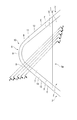
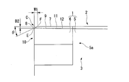
- FIG. 2 is an enlarged plan view of a corner portion in FIG. 1.
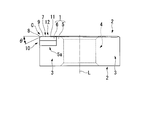
- FIG. 3 is an enlarged side view of a corner portion in FIG. 2.
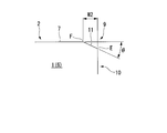
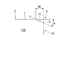
- VV sectional drawing in FIG. It is WW sectional drawing in FIG.
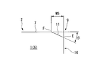
- XX sectional drawing in FIG. It is YY sectional drawing in FIG.
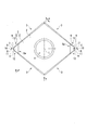
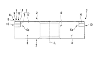
- the insert body 1 is formed in a polygonal plate shape, specifically, a rhombus flat plate shape having an acute corner portion angle of 80 °, and two polygonal surfaces (rhombus surface) 2; Four rectangular side surfaces 3 arranged around these polygonal surfaces 2 are provided.
- an attachment hole 4 is formed that has a circular cross section centering on the insert center line L passing through the centers of these polygonal surfaces 2 and penetrates the insert body 1.
- the two polygonal surfaces 2 have a planar shape perpendicular to the insert center line L.
- the insert body 1 of the present embodiment is a polygonal surface out of the two polygonal surfaces 2 of the base metal 5 formed in a substantially polygonal plate shape as described above from a hard material such as cemented carbide.
- a hard material such as cemented carbide.
- Two corners C at two acute angles are formed with L-shaped cutouts 5a, and cBN having a hardness higher than that of the base metal 5 at the cutouts 5a.
- Triangular plate-shaped cutting blade tips 6 made of a sintered body or a diamond sintered body are joined by brazing or the like to form a polygonal plate shape (diamond flat plate shape) as shown in FIGS. ing.
- the two corner portions C of one polygonal surface 2 to which the cutting edge tips 6 are joined in this manner are flush with the polygonal surface 2 on the cutting edge tips 6 of the polygonal surface 2.
- a corner blade 8 having a rake face 7 and having a convex curve shape such as a convex arc as shown in FIG. 4 in a plan view viewed from the insert center line L direction is formed facing the rake face 7. .
- the rake face 7 is also a flat surface perpendicular to the insert center line L.
- the insert body 1 of the present embodiment basically conforms to ISO 13399 (JIS-B4120-1998) except for the periphery of the corner portion C.
- a rake face 7 is formed on the one polygonal surface 2 so that the two edge portions of the one polygonal surface 2 connected to the corner C are in direct contact with the corner blade 8 in this embodiment.
- a wiper blade 9 having a convex curve shape such as a convex arc having a radius of curvature larger than that of the corner blade 8 in a plan view as viewed from the insert center line L direction is formed facing the rake face 7. . Therefore, of the four side surfaces 3 arranged around the polygonal surface 2, the two side surfaces 3 intersecting the intersecting ridge line portion connected to the corner portion C have at least the corner blade 8 and the wiper on the rake surface 7 side. A flank 10 connected to the blade 9 is formed.
- the cutting insert of the present embodiment is basically a negative type cutting insert in which the flank 10 extends in a direction perpendicular to the rake face 7, from the flank 10 of the corner blade 8 and the end of the wiper blade 9. However, on the side opposite to the corner blade 8, the flank 10 extends in the direction perpendicular to the rake face 7 in this way.
- Chamfer honing is applied from the corner blade 8 formed in the corner portion C to the wiper blades 9 on both sides thereof, and the rake face 7 and the flank face 10 of the corner blade 8 and the wiper blade 9 intersect.
- a chamfer honing surface 11 is formed in the ridge line portion. The chamfer honing surface 11 is formed in a direction in which the chamfer honing surface 11 is parallel to the rake surface 7 in a cross section orthogonal to the corner blade 8 and the wiper blade 9 as shown in FIGS. 2, 3 and 5 to 10.
- the honing angle ⁇ to be made is constant.
- the honing width of the chamfer honing surface 11 that is, the width in the direction parallel to the rake surface 7 of the chamfer honing surface 11 in the cross section orthogonal to the corner blade 8 and the wiper blade 9 (opposite the rake surface 7).
- the width in the plan view as viewed from the insert center line L direction is formed so as to gradually increase as the wiper blade 9 moves away from the corner blade 8.
- the honing width W1 of the corner blade 8 shown in FIG. 2 is constant, and the honing widths W2 to W6 of the wiper blade 9 as shown in FIGS. 6 to 10 are the corner blade 8 and the wiper blade. 9 is formed so as to gradually increase from the contact point 9 to the opposite side of the corner blade 8.
- the honing width W2 to W6 of the wiper blade 9 gradually increases as the distance from the corner blade 8 increases.
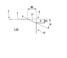
- the honing angle ⁇ is constant, as shown in FIG. So that the ridge line E between the chamfer honing surface 11 and the flank 10 that is the cutting edge of the blade faces the polygonal surface 2 side opposite to the polygonal surface 2 on which the rake face 7 is formed as the distance from the corner blade 8 increases. Will be inclined.
- the honing angle ⁇ is constant and the honing widths W2 to W6 gradually increase as the honing width W2 to W6 moves away from the corner blade 8, so that the intersecting ridge line F between the chamfer honing surface 11 and the rake surface 7 is also shown in FIG.
- the angle ⁇ formed by the intersecting ridge line F away from the intersecting ridge line E with respect to the intersecting ridge line E in the plan view is set to 1 ° in the present embodiment.
- the intersecting ridge line E between the chamfer honing surface 11 and the flank 10 in the wiper blade 9 is a polygonal surface 2 opposite to the rake surface 7.
- the range inclined to the side is also 0. 0 with respect to the intersecting ridgeline E between the chamfer honing surface 11 and the flank 10 in the corner blade 8 in the direction perpendicular to the polygonal surface 2 on which the rake surface 7 is formed.
- the range is set to 0250 mm or less, and more preferably set to 0.0196 mm or less. For example, in this embodiment, the range is 0.0179 mm.
- a difference D1-D2 between the chamfer honing surface 11 and the depth D2 in the direction of the insert center line L from the rake face 7 to the intersecting ridge line E in the blade 8 is set to a range of 0.0250 mm or less.
- the honing angle ⁇ that is constant from the corner blade 8 to the wiper blade 9 is preferably in the range of 14 ° to 26 °, and is set to 25 ° in this embodiment.
- the maximum honing width W6 in the wiper blade 9 is desirably larger than the honing width W1 in the corner blade 8 in the range of 0.115 mm to 0.180 mm.
- the depth D2 of the corner blade 8 is preferably in the range of 0.0274 mm to 0.0732 mm, and the depth D1 of the wiper blade 9 is in the range of 0.0319 mm to 0.0878 mm from the depth D2. It is desirable to increase the size.
- the radius of curvature of the wiper blade 9 is larger than the radius of curvature of the corner blade 8 in the range of 9.5 mm to 10.5 mm.
- the length of the wiper blade 9 (the length of a straight line connecting the contact point with the corner blade 8 and the terminal end of the wiper blade 9 in the plan view) is preferably in the range of 0.33 mm to 0.40 mm. In this embodiment, it is 0.4 mm.
- the portion of the wiper blade 9 that is opposite to the corner blade 8 from the end of the wiper blade 9 is a main cutting edge 12 that is linear in the plan view, that is, a straight line with the wiper blade 9 that is convex in the plan view.
- the point of contact with the main cutting edge 12 forming a shape is the end of the wiper blade 9 opposite to the corner edge 8.
- the chamfer honing surface 11 of the main cutting edge 12 maintains the angle ⁇ formed by the intersecting ridge line F with the rake face 7 of the wiper blade 9 with respect to the intersecting ridge line E in the plan view. It extends to an obtuse corner of the polygonal surface 2.
- the intersecting ridge line E is also formed on the side of the polygonal surface 2 opposite to the polygonal surface 2 on which the rake face 7 is formed along the main cutting edge 12 and away from the corner edge 8 as shown in FIGS. It is inclined and is rounded up to the polygonal surface 2 on which the rake face 7 is formed at the obtuse corner.
- the cutting insert configured as described above is seated on an insert mounting seat formed on the holder of the blade-type replaceable cutting tool and can be attached and detached by a clamp pin, a lever, a clamp screw or the like inserted through the mounting hole 4. It is attached.
- the rake face 7 is directed so as to face the rotating direction of the rotating work material
- the corner blade 8 is directed in the feed direction with respect to the work material
- the corner blade 8 is opposite to the feed direction.
- the wiper blade 9 extending in the direction protrudes slightly in the cutting direction into the work material than the corner blade 8 and is given a negative side rake angle and a predetermined side clearance angle.
- the honing angle ⁇ of the chamfer honing surface 11 formed from the corner blade 8 to the wiper blade 9 is constant, and the honing width gradually increases as the wiper blade 9 moves away from the corner blade 8. ing.
- the intersection ridgeline E between the chamfer honing surface 11 and the flank 10 in the wiper blade 9 is inclined so as to be directed toward the polygonal surface 2 opposite to the rake surface 7 as it is away from the corner blade 8 as described above. Will do.
- the chamfer honing surface 11 and the wiper blade 9 can be formed by polishing the ISO standard cutting insert described above. That is, in the case of this embodiment, the insert body 1 is formed so as to be an ISO standard cutting insert in a state where the cutting edge tip 6 is joined to a base metal 5 such as a cemented carbide, and the insert body 1 described above.
- the side surface 3 on the corner portion C side is polished to form a flank 10 of the wiper blade 9 that bends toward the corner portion C side, and at the intersecting ridge line portion between the two side surfaces 3 on the corner portion C side.
- the present invention can be applied relatively easily.
- the cutting edge tip 6 is joined in this way, it is possible to prevent the boundary portion with the base metal 5 from being damaged.
- the entire insert body 1 is a cutting insert formed of a sintered material such as a cemented carbide, a dedicated mold is required to mold the green compact sintered on the insert body 1. In addition, the manufacturing cost of the cutting insert can be suppressed.
- the cross ridge line E between the chamfer honing surface 11 and the flank 10 in the wiper blade 9 is a rake face with respect to the cross ridge line E between the chamfer honing surface 11 and the flank 10 in the corner blade 8.
- it In the direction perpendicular to the polygonal surface 2 on which the surface 7 is formed, it is inclined toward the polygonal surface 2 side opposite to the rake face 7 within a range of 0.0250 mm or less as it is away from the corner blade 8.
- this range be a range of 0.0196 mm or less as described above.
- this intersecting ridge line E is in a range of 0.0070 mm or more with respect to the intersecting ridge line E between the chamfer honing surface 11 and the flank 10 in the corner blade 8 (the difference D1-D2 between the depths D1 and D2 is It is desirable to incline toward the polygonal surface 2 side opposite to the rake face 7 in a range of 0.0070 mm or more.
- the flank 10 of the wiper blade 9 that is curved on the side surface 3 of a general ISO standard cutting insert is formed, and the flank of the corner blade 8 is further in contact with the flank 10 of the wiper blade 9.
- the chamfer honing surface 11 is formed after forming the surface 10 at the intersecting ridge line portion between the two side surfaces 3, the tip of the corner blade 8 in the bisector direction of the corner portion C in the plan view is polished. It will be located inside the insert body 1 with respect to the case where processing is not performed.
- the flank 10 of the wiper blade 9 is in contact with the curved flank 10.
- the flat flank 10 is polished and formed toward the tip of the corner blade 8, and the flank 10 of the corner blade 8 is in contact with the flat flank 10, and the position of the tip is ISO standard.
- a rake surface 7 is formed between the corner blade 8 and the wiper blade 9. What is necessary is just to form the linear straight blade which touches the corner blade 8 and the wiper blade 9 in the opposing planar view.
- the corner blade 8 is moved in the bisector direction of the corner portion C without changing the radius of curvature of the corner blade 8 or the wiper blade 9.
- the projecting end can be set at the same position as the ISO standard cutting insert. For this reason, even if the program is not corrected by the cutting process in the NC lathe, it is possible to prevent uncut parts during the copying process.
- the honing width W1 of the corner blade 8 is constant, but the honing width gradually increases from the tip of the corner blade 8 located on the bisector of the corner portion C toward the wiper blade 9.
- the honing width may gradually increase from the middle of the corner blade 8 toward the wiper blade 9.
- the rake surface 7 is formed by the intersection ridge line E between the chamfer honing surface 11 and the flank 10 in the wiper blade 9.
- the depth D1 of the chamfer honing surface 11 in the direction of the insert center line L from the rake face 7 to the intersecting ridge line E at the end of the wiper blade 9 in the direction perpendicular to the formed polygonal surface 2, and the corner blade 8 An example is given and the effect is demonstrated about the difference D1-D2 with the depth D2 of the insert centerline L direction of the chamfer honing surface 11 from the rake face 7 to the intersection ridgeline E in FIG.
- the honing angle ⁇ is in the range of 14 ° to 26 °
- the maximum honing width W6 in the wiper blade 9 is in the range of 0.115 mm to 0.180 mm
- the ridge line 7 from the rake face 7 at the end of the wiper blade 9 is intersected.
- the insert center line L depth D1 of the chamfer honing surface 11 to E is in the range of 0.0319 mm to 0.0878 mm, and the insert center of the chamfer honing surface 11 from the rake face 7 to the intersecting ridge line E in the corner blade 8
- Tables 1 and 6 show the depths D1 and D2 and the difference D1 ⁇ D2 and the honing width W6 as Examples 1 to 6.
- the depth D1 and the depth D2 are equal and the difference D1-D2 is 0, that is, the intersection of the chamfer honing surface 11 and the flank 10 in the wiper blade 9
- the ridge line E moves away from the corner blade 8
- it is not inclined so as to be directed to the polygonal surface 2 side opposite to the rake face 7, and is inclined, but the inclination is small and the difference D1-D2 is 0.0070 mm.
- the cutting inserts of Examples 1 to 6 and Comparative Examples 1 to 4 are basically the CNGA120408 type in ISO 13399 (JIS-B4120-1998) except for the periphery of the corner portion C. Further, the honing angle ⁇ is calculated from the honing width W6 and the depth D1, but in Examples 1 to 6, they are 14 °, 15 °, 15 °, 25 °, 26 °, and 26 ° in this order, and Comparative Examples 1 to At 4, the angles are 25 °, 15 °, 25 °, and 35 ° in this order. Furthermore, a cBN sintered body was used as the cutting edge tip 6.
- the outer diameter continuous turning was performed on a cylindrical work material having a diameter of 30 mm and a length of 100 mm made of SCr420 (hardness 60HRc), and the cutting speed
- the cutting insert life was determined under the conditions of Vc: 160 m / min, feed amount per rotation of the work material fr: 0.2 mm / rev, and cutting amount ap: 0.15 mm.
- the cutting length (km) when the surface roughness Rz of the work material (maximum height roughness in JIS-B0601-2001) is 6.3 ⁇ m or more is defined as the life. Table 1 also shows the cutting length at the time when this life is reached.
- the cutting inserts of Examples 1 to 6 do not generate chatter vibrations, and all can obtain a cutting length of 10 km or more, and are highly accurate and stable. It was possible to carry out the cutting process for a long time. Particularly, in Examples 1 to 4 and Example 6 in which the difference D1-D2 is in the range of 0.0196 mm or less, a cutting length exceeding 10 km is obtained until the lifetime. From this result, it can be seen that the difference D1-D2 is preferably in the range of 0.0196 mm or less, more preferably in the range of 0.0196 mm or less, and further preferably in the range of 0.0070 mm or more. .
- the present invention relates to a cutting insert that is attached to a cutting edge replaceable bite or the like and performs turning of a work material.
- the corner portion of the polygonal surface of the polygonal plate-like insert body has a rake face on the polygonal face and has a convex curve shape in plan view facing the rake face.
- a corner blade is formed, and a wiper blade having a convex curve shape with a radius of curvature larger than that of the corner blade is formed on a side ridge portion of the polygonal surface connected to the corner blade in a plan view facing the rake face.
- a chamfer honing surface is formed from the corner blade to the wiper blade.
- the chamfer honing surface has a constant honing angle and a honing width in a plan view facing the rake surface. Since the blade gradually increases as it moves away from the corner blade, it can be manufactured at low cost without the need for a dedicated mold, and cBN sintering It can also be applied to cutting inserts equipped with diamond sintered bodies, and by suppressing the wiper blade from rubbing against the work material and suppressing the increase in cutting resistance, it can be used for inner diameter machining and small diameter machining by high feed. It is possible to perform stable cutting with high accuracy by preventing chatter vibration and waviness of the machined surface even when machining the outer diameter of the material.
Landscapes
- Engineering & Computer Science (AREA)
- Mechanical Engineering (AREA)
- Cutting Tools, Boring Holders, And Turrets (AREA)
Abstract
La présente invention concerne une plaquette de coupe caractérisée en ce que: une arête de coin est formée dans une section de coin d'une surface polygonale d'un corps de plaquette de forme polygonale aplatie, l'arête de coin présentant une surface de coupe sur la surface polygonale et formant une forme courbe convexe dans une vue en plan faisant face à la surface de coupe; une arête racleuse est formée sur une section de crête latérale de la surface polygonale dans la continuité de l'arête de coin, l'arête racleuse formant une forme courbe convexe présentant un rayon de courbure supérieur à celui de l'arête de coin dans une vue en plan faisant face à la surface de coupe; et une surface de polissage de chanfrein est formée de l'arête de coin à l'arête racleuse, la surface de polissage de chanfrein présentant un angle de polissage fixe, et la largeur de polissage dans une vue en plan faisant face à la surface de coupe augmentant progressivement dans l'arête racleuse à mesure que l'on s'éloigne de l'arête de coin.
Applications Claiming Priority (2)
| Application Number | Priority Date | Filing Date | Title |
|---|---|---|---|
| JP2016127690 | 2016-06-28 | ||
| JP2016-127690 | 2016-06-28 |
Publications (1)
| Publication Number | Publication Date |
|---|---|
| WO2018003873A1 true WO2018003873A1 (fr) | 2018-01-04 |
Family
ID=60786720
Family Applications (1)
| Application Number | Title | Priority Date | Filing Date |
|---|---|---|---|
| PCT/JP2017/023789 Ceased WO2018003873A1 (fr) | 2016-06-28 | 2017-06-28 | Plaquette de coupe |
Country Status (2)
| Country | Link |
|---|---|
| JP (1) | JP6930245B2 (fr) |
| WO (1) | WO2018003873A1 (fr) |
Cited By (1)
| Publication number | Priority date | Publication date | Assignee | Title |
|---|---|---|---|---|
| US20200130072A1 (en) * | 2018-10-31 | 2020-04-30 | Kyocera Corporation | Cutting insert, cutting tool, and method for manufacturing machined product |
Families Citing this family (2)
| Publication number | Priority date | Publication date | Assignee | Title |
|---|---|---|---|---|
| JP6512499B1 (ja) * | 2018-05-29 | 2019-05-15 | 株式会社タンガロイ | 切削インサート |
| JP7794386B1 (ja) * | 2024-11-01 | 2026-01-06 | 住友電工ハードメタル株式会社 | 切削インサートおよび切削工具 |
Citations (6)
| Publication number | Priority date | Publication date | Assignee | Title |
|---|---|---|---|---|
| JPH0253302U (fr) * | 1988-10-12 | 1990-04-17 | ||
| JPH0498503U (fr) * | 1991-02-01 | 1992-08-26 | ||
| JP2001157903A (ja) * | 1999-11-29 | 2001-06-12 | Mitsubishi Materials Corp | スローアウェイチップ |
| JP2007290059A (ja) * | 2006-04-24 | 2007-11-08 | Tungaloy Corp | 超高圧焼結体切削工具 |
| JP2012206246A (ja) * | 2011-03-30 | 2012-10-25 | Mitsubishi Materials Corp | 切削インサート |
| WO2016043029A1 (fr) * | 2014-09-18 | 2016-03-24 | 京セラ株式会社 | Plaquette de coupe, outil de coupe et procédé de fabrication pour objet destiné à un traitement de coupe |
Family Cites Families (1)
| Publication number | Priority date | Publication date | Assignee | Title |
|---|---|---|---|---|
| DE3823199A1 (de) * | 1988-07-08 | 1990-01-11 | Feldmuehle Ag | Schneidplatte fuer spanabhebende bearbeitung |
-
2017
- 2017-06-22 JP JP2017122496A patent/JP6930245B2/ja active Active
- 2017-06-28 WO PCT/JP2017/023789 patent/WO2018003873A1/fr not_active Ceased
Patent Citations (6)
| Publication number | Priority date | Publication date | Assignee | Title |
|---|---|---|---|---|
| JPH0253302U (fr) * | 1988-10-12 | 1990-04-17 | ||
| JPH0498503U (fr) * | 1991-02-01 | 1992-08-26 | ||
| JP2001157903A (ja) * | 1999-11-29 | 2001-06-12 | Mitsubishi Materials Corp | スローアウェイチップ |
| JP2007290059A (ja) * | 2006-04-24 | 2007-11-08 | Tungaloy Corp | 超高圧焼結体切削工具 |
| JP2012206246A (ja) * | 2011-03-30 | 2012-10-25 | Mitsubishi Materials Corp | 切削インサート |
| WO2016043029A1 (fr) * | 2014-09-18 | 2016-03-24 | 京セラ株式会社 | Plaquette de coupe, outil de coupe et procédé de fabrication pour objet destiné à un traitement de coupe |
Cited By (1)
| Publication number | Priority date | Publication date | Assignee | Title |
|---|---|---|---|---|
| US20200130072A1 (en) * | 2018-10-31 | 2020-04-30 | Kyocera Corporation | Cutting insert, cutting tool, and method for manufacturing machined product |
Also Published As
| Publication number | Publication date |
|---|---|
| JP6930245B2 (ja) | 2021-09-01 |
| JP2018001401A (ja) | 2018-01-11 |
Similar Documents
| Publication | Publication Date | Title |
|---|---|---|
| CN110035851B (zh) | 切削刀具 | |
| JP4908201B2 (ja) | 回転防止工具ホルダー及び切削用チップ工具 | |
| JP4603550B2 (ja) | 高速送りの正面削り用切削インサート | |
| CN109475944B (zh) | 车削刀片 | |
| CN104520067B (zh) | 制造立方氮化硼切削工具的方法及立方氮化硼切削工具 | |
| TWI436840B (zh) | Ball cutter | |
| CN1326653C (zh) | 具有擦拭器半径的铣刀 | |
| TWI754082B (zh) | 具有切屑形成配置的負精車削嵌件 | |
| US11052466B2 (en) | Cutting tool and manufacturing method thereof | |
| JP4585243B2 (ja) | 超精密加工用単結晶ダイヤモンド切削工具 | |
| US10507530B2 (en) | Cutting tool | |
| CN114951720A (zh) | 切削刀片 | |
| JP6930245B2 (ja) | 切削インサート | |
| JP2017159440A (ja) | 切削インサートおよび刃先交換式切削工具 | |
| JP2007021622A (ja) | チップおよび転削工具 | |
| CN101568405A (zh) | 磨削形成方法以及旋转切削工具 | |
| JP6658806B2 (ja) | 切削工具 | |
| JP2007021623A (ja) | チップおよび転削工具 | |
| JP5887859B2 (ja) | 切削インサート | |
| KR102470286B1 (ko) | 경면 가공 방법 및 경면 가공 공구 | |
| CA2254233A1 (fr) | Insertion au plan de joint en t | |
| WO2017150541A1 (fr) | Insert de coupe et outil de coupe à bord remplaçable | |
| JP2001269810A (ja) | スローアウェイチップ | |
| JP6658805B2 (ja) | 切削インサート | |
| JP7481377B2 (ja) | 仕上げ加工用工具 |
Legal Events
| Date | Code | Title | Description |
|---|---|---|---|
| 121 | Ep: the epo has been informed by wipo that ep was designated in this application |
Ref document number: 17820227 Country of ref document: EP Kind code of ref document: A1 |
|
| NENP | Non-entry into the national phase |
Ref country code: DE |
|
| 122 | Ep: pct application non-entry in european phase |
Ref document number: 17820227 Country of ref document: EP Kind code of ref document: A1 |