WO2018003948A1 - Corps de fraise cylindrique deux tailles et fraise cylindrique deux tailles à rayon - Google Patents
Corps de fraise cylindrique deux tailles et fraise cylindrique deux tailles à rayon Download PDFInfo
- Publication number
- WO2018003948A1 WO2018003948A1 PCT/JP2017/024039 JP2017024039W WO2018003948A1 WO 2018003948 A1 WO2018003948 A1 WO 2018003948A1 JP 2017024039 W JP2017024039 W JP 2017024039W WO 2018003948 A1 WO2018003948 A1 WO 2018003948A1
- Authority
- WO
- WIPO (PCT)
- Prior art keywords
- end mill
- blade
- corner
- point
- rake face
- Prior art date
- Legal status (The legal status is an assumption and is not a legal conclusion. Google has not performed a legal analysis and makes no representation as to the accuracy of the status listed.)
- Ceased
Links
Images



Classifications
-
- B—PERFORMING OPERATIONS; TRANSPORTING
- B23—MACHINE TOOLS; METAL-WORKING NOT OTHERWISE PROVIDED FOR
- B23C—MILLING
- B23C5/00—Milling-cutters
- B23C5/02—Milling-cutters characterised by the shape of the cutter
- B23C5/10—Shank-type cutters, i.e. with an integral shaft
-
- B—PERFORMING OPERATIONS; TRANSPORTING
- B23—MACHINE TOOLS; METAL-WORKING NOT OTHERWISE PROVIDED FOR
- B23C—MILLING
- B23C5/00—Milling-cutters
- B23C5/16—Milling-cutters characterised by physical features other than shape
-
- B—PERFORMING OPERATIONS; TRANSPORTING
- B23—MACHINE TOOLS; METAL-WORKING NOT OTHERWISE PROVIDED FOR
- B23C—MILLING
- B23C2210/00—Details of milling cutters
- B23C2210/02—Connections between the shanks and detachable cutting heads
-
- B—PERFORMING OPERATIONS; TRANSPORTING
- B23—MACHINE TOOLS; METAL-WORKING NOT OTHERWISE PROVIDED FOR
- B23C—MILLING
- B23C2210/00—Details of milling cutters
- B23C2210/04—Angles
- B23C2210/0407—Cutting angles
- B23C2210/0421—Cutting angles negative
- B23C2210/0435—Cutting angles negative radial rake angle
-
- B—PERFORMING OPERATIONS; TRANSPORTING
- B23—MACHINE TOOLS; METAL-WORKING NOT OTHERWISE PROVIDED FOR
- B23C—MILLING
- B23C2210/00—Details of milling cutters
- B23C2210/04—Angles
- B23C2210/0407—Cutting angles
- B23C2210/0442—Cutting angles positive
- B23C2210/045—Cutting angles positive axial rake angle
-
- B—PERFORMING OPERATIONS; TRANSPORTING
- B23—MACHINE TOOLS; METAL-WORKING NOT OTHERWISE PROVIDED FOR
- B23C—MILLING
- B23C2210/00—Details of milling cutters
- B23C2210/04—Angles
- B23C2210/0485—Helix angles
-
- B—PERFORMING OPERATIONS; TRANSPORTING
- B23—MACHINE TOOLS; METAL-WORKING NOT OTHERWISE PROVIDED FOR
- B23C—MILLING
- B23C2210/00—Details of milling cutters
- B23C2210/08—Side or top views of the cutting edge
- B23C2210/082—Details of the corner region between axial and radial cutting edges
-
- B—PERFORMING OPERATIONS; TRANSPORTING
- B23—MACHINE TOOLS; METAL-WORKING NOT OTHERWISE PROVIDED FOR
- B23C—MILLING
- B23C2210/00—Details of milling cutters
- B23C2210/08—Side or top views of the cutting edge
- B23C2210/084—Curved cutting edges
-
- B—PERFORMING OPERATIONS; TRANSPORTING
- B23—MACHINE TOOLS; METAL-WORKING NOT OTHERWISE PROVIDED FOR
- B23C—MILLING
- B23C2210/00—Details of milling cutters
- B23C2210/54—Configuration of the cutting part
-
- B—PERFORMING OPERATIONS; TRANSPORTING
- B23—MACHINE TOOLS; METAL-WORKING NOT OTHERWISE PROVIDED FOR
- B23C—MILLING
- B23C2226/00—Materials of tools or workpieces not comprising a metal
- B23C2226/18—Ceramic
-
- B—PERFORMING OPERATIONS; TRANSPORTING
- B23—MACHINE TOOLS; METAL-WORKING NOT OTHERWISE PROVIDED FOR
- B23C—MILLING
- B23C2226/00—Materials of tools or workpieces not comprising a metal
- B23C2226/73—Silicon nitride
-
- B—PERFORMING OPERATIONS; TRANSPORTING
- B23—MACHINE TOOLS; METAL-WORKING NOT OTHERWISE PROVIDED FOR
- B23C—MILLING
- B23C2240/00—Details of connections of tools or workpieces
- B23C2240/32—Connections using screw threads
Definitions
- the present disclosure relates to an end mill main body and a radius end mill in which a corner R blade projecting in an arc shape is formed on an outer peripheral portion of a tip portion of the end mill main body.
- a radius end mill made of cemented carbide in which a corner R blade projecting in an arc shape toward the outside is formed between a bottom blade and an outer peripheral blade is known.
- a ceramic radius end mill made of a material such as silicon nitride has been developed.
- Patent Document 1 proposes a technique for preventing a corner R blade from being damaged by providing a corner R rake face (corner R gushed) and providing a starting point of the corner R rake face on the bottom edge. Has been.
- the end mill main body in one aspect of the present disclosure relates to a ceramic end mill main body that constitutes a tip end side of a radius end mill rotated around an axis.
- This end mill main body is formed on the outer periphery of the end mill body on the outer periphery of the chip discharge groove and the outer peripheral ridge line of the chip discharge groove formed so as to be twisted backward in the rotation direction from the front end side toward the rear end side.
- the intersection point between the corner R blade and the bottom blade is A point
- the intersection point between the corner R blade and the outer peripheral blade is B point
- the intersection point of the A straight line passing through point A parallel to the axis and the B straight line passing through point B perpendicular to the axis is defined as point C.
- the area surrounded by the A straight line, the B straight line, and the corner R blade was divided by the C straight line passing through the C point and the midpoint of the straight line from the A point to the B point
- the region was divided by the C straight line.
- a region on the A point side is a region A
- a region on the B point side is a region B.
- the corner R rake face does not exist in the region A, includes the point B, and is formed at least in the region B.
- the corner R rake face (that is, the corner R gash) is not formed in the area A on the bottom blade side but includes the point B and is formed at least in the area B.
- the cutting edge at the outer edge portion (that is, the outer peripheral edge) of the corner R rake face is formed not at the area A but at the outer edge of the area B among the corner R blades extending from the point A to the point B.
- the outer peripheral blade side reaches from the point B or B point to a part of the outer peripheral blade. Therefore, there is an effect that the corner R blade is not easily damaged during the cutting process.
- the cutting edge at the outer peripheral edge of the corner R rake face has a first end (starting point) on the bottom cutting edge side and a second end (end point) on the outer peripheral cutting edge side.
- a 1st end part exists in the position away from A point which is an intersection of a bottom blade and a corner R blade, and a 2nd end part exists in an outer peripheral blade side from B point or B point. Therefore, at the time of cutting, it is difficult to apply a large cutting load to the first end portion of the outer peripheral end of the corner R rake face. Therefore, there is an advantage that the corner R blade is hardly damaged.
- the corner R rake face does not exist in the region A, includes the point B, and is formed at least in the region B”, as described above, the corner R rake face is formed.
- the corner R rake face may be smoothly connected to the outer peripheral blade. Further, in the present end mill body, as described above, the corner R rake face is formed between the bottom edge rake face and the chip discharge groove (so-called blade groove) so as to reach the corner R edge. Accordingly, the bottom edge rake face reaches not only the portion corresponding to the bottom edge but also the end of the corner R rake face in the area A and further in the area B on the bottom edge side.
- the end rake formed by the bottom blade may be -5 ° to -10 °, and the axial rake formed by the bottom blade rake face may be positive.
- welding is likely to occur on the cutting edge on the bottom edge side. I know.
- the end mill main body if the axial rake formed by the rake face of the bottom blade is positive, the occurrence of welding can be suppressed, but the tip of the cutting edge tends to be broken compared to, for example, cemented carbide.
- the end rake formed by the bottom blade is negative, such as ⁇ 5 ° to ⁇ 10 °, so that the occurrence of chipping at the tip of the cutting blade can be suppressed.
- the end mill main body has a remarkable effect that it can suppress the occurrence of welding and comprehensively suppress the occurrence of cutting edge defects.
- the “end rake” refers to a straight line (LE) extending from the center of the shaft to the outer peripheral edge of the bottom blade when viewed from the tip side along the axis, as shown in FIG. This is the angle ( ⁇ E) to be made.
- the end rake formed by the bottom blade being negative (that is, minus ( ⁇ )) indicates that the bottom blade is inclined backward with respect to the straight line (LE) in the rotational direction (K).
- the axial rake ( ⁇ A) formed by the bottom edge rake face is positive, as shown in FIG. 4 to be described later, the front end side (outer peripheral end) in the axial direction of the bottom edge rake face relative to the rear end side. In other words, it is formed so as to be positioned in front of the rotation direction.
- the axial rake formed by the bottom edge rake face may be + 1 ° to + 5 °. According to the study by the present inventors, it is found that when the axial rake formed by the rake face of the bottom blade is + 1 ° to + 5 °, the bottom blade and the corner R blade are less damaged and are suitable. ing.
- the end mill main body in another aspect of the present disclosure relates to a ceramic end mill main body that constitutes a tip end side of a radius end mill rotated around an axis.
- This end mill main body is formed on the outer periphery of the end mill body on the outer periphery of the chip discharge groove and the outer peripheral ridge line of the chip discharge groove formed so as to be twisted backward in the rotation direction from the front end side toward the rear end side.
- the end mill body has an end rake formed by the bottom blade of ⁇ 5 ° to ⁇ 10 °, and an axial rake formed by the rake face of the bottom blade is positive.
- This end mill main body has the same effects as the end mill main body shown in the column (2).
- the axial rake formed by the bottom edge rake face may be + 1 ° to + 5 °.
- the above-mentioned end mill main body has the same effects as the end mill main body shown in the column (3).
- the above-described end mill main body may have a corner R rake face provided so as to be in contact with the corner R edge between the bottom edge rake face and the chip discharge groove.
- cutting edge such as bottom edge and corner R blade is less than that which does not have corner R rake face provided to contact the corner R edge between the bottom edge rake face and the chip discharge groove.
- the above-mentioned end mill main body may be provided with a main body side connection portion that is detachably connected to a shank portion fixed to the rotating shaft of the machine tool on the rear end side of the end mill main body.
- the end mill main body and the shank portion can be detachably connected using the main body side connecting portion.
- the shank portion is a member constituting the rear end side of the radius end mill, and is a rod-like member that is fixed to the rotating shaft of the machine tool and rotates together with the end mill body as the rotating shaft rotates.
- a radius end mill includes an end mill body that processes a workpiece on a front end side, and a radius that includes a shank portion that is fixed to a rotating shaft of a machine tool on a rear end side.
- the end mill body described in any one of the above (1) to (6) may be provided as the end mill body.
- This radius end mill has various effects due to the end mill main body described above because the tip end side to be processed is constituted by the end mill main body described above. (9)
- the radius end mill described above is made of ceramic, and the end mill main body and the shank portion may be integrally formed.
- this radius end mill has a ceramic end mill body on the front end side and a ceramic portion on the rear end side thereof (for example, a ceramic shank portion fixed to the rotating shaft of the machine tool) integrally formed. Ceramic parts.
- the above-described radius end mill has an end mill main body and a shank portion detachably connected, and the end mill main body is detachably connected to the shank portion at the rear end side thereof. You may provide the connection part.
- the term “made of ceramic” means that the sintered body is composed of a material mainly composed of ceramic, that is, a material containing more than 50% by volume of ceramic (preferably 90% by volume or more). ing.
- the radius end mill 1 is a substantially cylindrical cutting tool configured using a ceramic such as silicon nitride.
- the workpiece is fed in a predetermined direction perpendicular to the axis O direction while being rotated in the rotation direction (K direction) of the axis O by a machine tool (not shown).
- K direction rotation direction
- a workpiece (not shown) that is an object is cut.
- the radius end mill 1 is provided with a substantially cylindrical end mill body (that is, a head portion) 3 having an axis O as a center at the tip end side thereof. Further, the radius end mill 1 is provided with a shank portion 5 on the rear end side of the end mill main body 3 (upward in FIG. 1) for mounting on the spindle of the machine tool. The end mill body 3 is provided with a cutting edge portion 7 for cutting a workpiece on the distal end side.
- a plurality of chips for example, four lines are discharged from the front end side (downward in FIG. 1) toward the rear end side so as to be twisted rearward in the rotational direction of the axis O.
- Grooves so-called blade grooves: flutes 9 are formed at equal intervals in the circumferential direction.
- the outer peripheral edge 13 is provided on the outer peripheral side ridge line of the wall surface 9 a facing the rotation direction of the chip discharge grooves 9. That is, the outer peripheral blade 13 is provided at a ridge line portion that is a boundary portion between the wall surface 9 a and the outer peripheral surface (that is, the outer peripheral flank 11) of the cutting edge portion 7 that continues to the rear side in the rotation direction. Similar to the chip discharge groove 9, the outer peripheral blade 13 is formed to be twisted to the rear side in the rotation direction of the axis O from the front end side toward the rear end side.
- An outer peripheral edge scooping surface 15 is formed along the outer peripheral edge 13 on the wall surface 9a.
- a gash 17 is formed at the tip portion of the cutting edge portion 7 so that the opening portion on the tip side of each chip discharge groove 9 is cut into a groove shape on the axis O side. That is, the gasche 17 is formed so as to reach the chip discharge groove 9 from the tip portion of the end mill body 3.
- the wall surface facing the rotation direction of the gasche 17 is a bottom blade rake surface 19, and a bottom blade 21 is formed on the tip side ridge line so as to extend in the radial direction from the vicinity of the axis O. That is, the bottom blade 21 is formed at the tip portion of the end mill body 3.
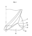
- a corner R rake face (that is, a corner R gouache) 27 is provided as a wall face that is cut out so as to be in contact with and faces the rotation direction.
- corner R rake face 27 When the corner R rake face 27 is formed, it is bent smoothly by scraping the bottom edge rake face 19 and the chip discharge groove 9 (so-called ridge line portion) toward the outer peripheral end side. And can be formed to reach the outer peripheral end.
- the ridgeline 25 which the edge part of the bottom blade scoop surface 19 and the edge part of the chip discharge groove
- the axis O is included.
- the A straight line (LA) passing through point A and perpendicular to the axis O is perpendicular to the axis O.
- An intersection point with a B straight line (LB) passing through the point B is defined as a point C. Furthermore, when the area surrounded by the A straight line, the B straight line, and the corner R blade 23 is divided by a C straight line (LC) passing through the C point and the midpoint of the straight line (L1) from the A point to the B point.
- the region on the A point side divided by the C straight line is defined as region A (RA), and the region on the B point side is defined as region B (RB).
- the corner R rake face 27 does not exist in the region A, includes the point B, and is formed at least in the region B.
- the outer peripheral edge cutting edge 28 of the corner R rake face 27 in the region B is shifted from the first end 27 a on the bottom edge 21 side of the outer peripheral edge of the corner R rake face 27 to the It is formed so as to reach the two end portions 27b.
- the second end portion 27b coincides with the B point.
- the shape of the corner R blade 23 in the plane including the axis O and the point B for example, a part (arc) of a circle having a radius of 1.5 mm can be adopted, but other than that, it is convex outward.
- a smoothly curved arc shape can be adopted.
- the corner R rake face 27 is formed not as a region A on the bottom blade 21 side but as a continuous and smooth surface so as to include the point B and to exist at least in the region B.
- the outer edge portion of the corner R rake face 27 (that is, the cutting edge 28 which is the outer peripheral end) is formed on the outer edge of the region B instead of the region A of the corner R blade 23.
- the second end portion 27b of the cutting edge 28 on the outer peripheral blade 13 side reaches the point B.
- the cutting edge 28 at the outer peripheral end of the corner R rake face 27 is located away from the point A that is the intersection of the bottom blade 21 and the corner R blade 23 (specifically, the first end portion 27a that is a position in the region B). ), And the end point reaches point B.
- the corner R rake face 27 is formed so as to cut out the outer peripheral side between the bottom edge rake face 19 and the chip discharge groove 9. Therefore, the bottom blade rake face 19 reaches the end of the region A and the corner R rake face 27 on the bottom blade 21 side.
- FIG. 4 shows positive (+) and negative ( ⁇ ) of the axial rake ( ⁇ A).
- the axial rake ( ⁇ A) is an angle formed by the front end side (outer peripheral end) of the bottom edge rake face 19 in the axial direction with respect to the axis O. Specifically, the axial rake ( ⁇ A) formed by the bottom edge rake face 19 is in the range of + 1 ° to + 5 °.
- the end lake ( ⁇ E) formed by the bottom blade 21 is ⁇ 5 ° to ⁇ 10 ° in the negative ( ⁇ ) range.
- positive (+) and negative ( ⁇ ) of end rake ( ⁇ E) are shown.
- the end rake ( ⁇ E) is an angle formed between the straight line (LE) from the axial center (OC) to the outer peripheral end 21a of the bottom blade 21 and the bottom blade 21 when viewed from the tip side along the axis O. ( ⁇ E). [1-3. effect] Next, the effect of the first embodiment will be described.
- the corner R rake face 27 is formed not in the region A on the bottom blade 21 side but in the region B on the outer peripheral blade 13 side and includes the point B. .
- the cutting edge 28 at the outer edge portion of the corner R rake face 27 is formed not at the area A but at the outer edge of the area B in the corner R blade 23, and the cutting edge 28 reaches the point B. Therefore, there is an effect that the corner R blade 23 is not easily damaged during the cutting process.
- the corner R rake face 27 is in the region B away from the point A, which is the intersection of the bottom edge 21 and the corner R edge 23, with the first end 27a of the cutting edge 28 at the outer peripheral end thereof.
- the two end portions 27b coincide with the B point. Therefore, when cutting, a large cutting load is not easily applied to the first end portion 27a of the corner R rake face 27, so that there is an advantage that the corner R blade 23 is not easily damaged.
- the axial rake ( ⁇ A) formed by the bottom edge rake face 19 is positive (specifically, + 1 ° to + 5 °), it is possible to suppress the occurrence of welding, thereby Generation
- the axial rake ( ⁇ A) formed by the bottom edge rake face 19 positive chip evacuation is improved, biting of chips can be suppressed, and chipping of bottom edges and corner R blades can be prevented. Generation can be suppressed.
- the ceramic radius end mill 1 if the axial rake ( ⁇ A) formed by the bottom edge rake face 19 is positive, the generation of welding can be suppressed, but the cutting edge compared to, for example, cemented carbide.
- the end rake ( ⁇ E) formed by the bottom blade 21 is negative, such as ⁇ 5 ° to ⁇ 10 °. The occurrence of deficiency can be suppressed.
- each sample having an end rake of, for example, -7 ° within a range of -5 ° to -10 °, and an axial rake of + 1 °, + 5 °. was made.
- a cutting speed 600 m / min
- a feed amount 0.03 mm / t
- a cutting ap 0.5 mm
- ae 5 mm.
- the radius end mill 1, the end mill body 3, the chip discharge groove 9, the outer peripheral blade 13, the gash 17, the bottom blade rake surface 19, the bottom blade 21, the corner R blade 23, and the corner R rake surface 27 of the first embodiment are respectively This corresponds to an example of a radius end mill, an end mill main body, a chip discharge groove, an outer peripheral edge, a gash, a bottom edge rake face, a bottom edge, a corner R edge, and a corner R rake face of the present disclosure.
- the second embodiment will be described, but the description of the same contents as the first embodiment will be omitted or simplified. In addition, about the structure similar to 1st Embodiment, it demonstrates using the same number.
- the radius end mill 31 of the second embodiment has substantially the same configuration as the cutting edge portion 7 of the first embodiment.
- the axis line A straight line (LA) passing through point A parallel to the axis O and B straight through the point B perpendicular to the axis O (LB) when viewed from a direction perpendicular to the plane including O and passing through the point B ) Is the point C.
- the corner R rake face 27 does not exist in the region A, includes the point B, and is formed at least in the region B. Moreover, the second end portion 27b of the cutting edge 28 at the outer peripheral end of the corner R rake face 27 is formed on the outer peripheral blade 13 side beyond the B point, not the B point.
- the portion in the region B can also be called a part of the corner R blade 23, and reaches the second end portion 27 b beyond the point B. It can also be said that this part is a part of the outer peripheral blade 13.
- a corner R rake face 27 having a shape different from that of the first embodiment is provided between the bottom edge rake face 19 and the chip discharge groove 9. That is, the outer peripheral edge 28 of the corner R rake face 27 is formed so as to reach a part of the outer peripheral edge 13 from the point B (upward in FIG. 6).
- an exchangeable head portion 45 including an end mill main body 43 and a shank portion 47 are detachably and integrally connected. This is a head exchangeable cutting tool.
- the end mill main body 43 is made of ceramic, for example, using silicon nitride or the like, as in the first embodiment, and includes a cutting edge portion 7 on the tip side (lower side in FIG. 7).
- a main body side connection portion 49 made of, for example, steel (for example, alloy steel) is integrally fixed to the rear end side of the end mill main body 43.
- the main body side connection portion 49 includes a substantially disc-shaped base portion 51 and a connection convex portion 53 protruding from the rear end side of the base portion 51 along the axis O toward the rear end side.
- a male screw 53 a is formed on the distal end side of the outer peripheral surface of the connection convex portion 53.
- a projecting portion 55 of a prism (for example, a quadrangular prism) projecting toward the rear end along the axis O is formed on the rear end side of the end mill main body 43.
- a fitting concave portion 57 that is a prismatic (for example, quadrangular prism) -like space into which the protruding portion 55 is fitted is formed on the distal end side of the base portion 51.
- the projecting portion 55 of the end mill main body 43 is fitted into the fitting concave portion 57 of the base portion 51 and joined by a brazing material, so that the end mill main body 43 and the base portion 51 (and hence the main body side connection portion 49) are fixed integrally. Has been.
- a configuration in which the end mill main body 43 and the main body side connection portion 49 are integrated is referred to as a replaceable head portion 45.
- the shank portion 47 is a rod-shaped member made of, for example, steel, and a shank side connection portion 59 that is a recess into which the connection projection 53 is screwed is formed on the tip side thereof.
- a female screw 59 a that is screwed with the male screw 53 a of the connection convex portion 53 is formed on the inner peripheral surface of the shank side connection portion 59.
- Two parallel locking surfaces 61 are formed on the outer peripheral surface of the base portion 51 of the main body side connection portion 49. Therefore, when the end mill main body 43 (and hence the replaceable head portion 45) and the shank portion 47 are connected together, the connection convex portion 53 of the main body side connection portion 49 may be screwed into the shank side connection portion 59. When screwing, the replaceable head portion 45 is firmly fixed to the shank portion 47 by sandwiching the two locking surfaces 61 of the base portion 51 with a tool such as a wrench and turning the tool in the screwing direction. be able to.
- the third embodiment has the same effects as the first embodiment. Further, when the tip end side of the end mill main body 43 is worn or damaged by processing by the radius end mill 41, only the replaceable head portion 45 can be removed from the shank portion 47 and replaced.
- the formation range of the corner R rake face is not limited to the above embodiment, and can be freely set within the scope of the present disclosure.
- silicon nitride, sialon, alumina, zirconia, etc. are mentioned.
- a function of one component in each of the above embodiments may be shared by a plurality of components, or a function of a plurality of components may be exhibited by one component. Moreover, you may abbreviate
- at least a part of the configuration of each of the above embodiments may be added to or replaced with the configuration of another embodiment.
- all the aspects included in the technical idea specified from the wording described in the claims are embodiments of the present disclosure.
Landscapes
- Engineering & Computer Science (AREA)
- Mechanical Engineering (AREA)
- Milling Processes (AREA)
Abstract
Selon l'invention, dans un corps de fraise cylindrique deux tailles en céramique, des faces de coupe à angles arrondis sont formées de manière à ne pas comprendre de région (A) sur le côté bord de coupe d'extrémité, mais un point (B), et pour comprendre au moins une région (B). En d'autres mots, la première extrémité du bord de coupe de la partie bord externe de la face de coupe à angles arrondis est formée au niveau du bord externe de la région (B) du bord à angle arrondi, et la seconde extrémité du bord de coupe s'étend au moins jusqu'au point (B). Par conséquent, on obtient l'effet selon lequel le bord à angle arrondi n'est pas susceptible d'être endommagé pendant le travail de coupe. C'est-à-dire que la face de coupe à angles arrondis est formée de manière à présenter en tant que point de départ une première extrémité qui est distante du point (A), qui est le point d'intersection du bord de coupe d'extrémité et du bord à angle arrondi, et une seconde extrémité qui s'étend jusqu'au point (B). Ainsi, pendant le travail de coupe, le point de départ de la face de coupe à angles arrondis n'est pas soumis à de grands efforts de coupe. Par conséquent, le bord à angle arrondi n'est pas susceptible d'être endommagé.
Priority Applications (4)
| Application Number | Priority Date | Filing Date | Title |
|---|---|---|---|
| CN201780040959.XA CN109414769B (zh) | 2016-06-30 | 2017-06-29 | 端铣刀主体和圆角端铣刀 |
| EP17820302.2A EP3479941A4 (fr) | 2016-06-30 | 2017-06-29 | Corps de fraise cylindrique deux tailles et fraise cylindrique deux tailles à rayon |
| JP2017559138A JP6483860B2 (ja) | 2016-06-30 | 2017-06-29 | エンドミル本体及びラジアスエンドミル |
| US16/312,447 US11000906B2 (en) | 2016-06-30 | 2017-06-29 | Endmill body and radius end mill |
Applications Claiming Priority (2)
| Application Number | Priority Date | Filing Date | Title |
|---|---|---|---|
| JP2016130440 | 2016-06-30 | ||
| JP2016-130440 | 2016-06-30 |
Publications (1)
| Publication Number | Publication Date |
|---|---|
| WO2018003948A1 true WO2018003948A1 (fr) | 2018-01-04 |
Family
ID=60787301
Family Applications (1)
| Application Number | Title | Priority Date | Filing Date |
|---|---|---|---|
| PCT/JP2017/024039 Ceased WO2018003948A1 (fr) | 2016-06-30 | 2017-06-29 | Corps de fraise cylindrique deux tailles et fraise cylindrique deux tailles à rayon |
Country Status (5)
| Country | Link |
|---|---|
| US (1) | US11000906B2 (fr) |
| EP (1) | EP3479941A4 (fr) |
| JP (1) | JP6483860B2 (fr) |
| CN (1) | CN109414769B (fr) |
| WO (1) | WO2018003948A1 (fr) |
Cited By (2)
| Publication number | Priority date | Publication date | Assignee | Title |
|---|---|---|---|---|
| WO2019188135A1 (fr) * | 2018-03-27 | 2019-10-03 | 日本特殊陶業株式会社 | Corps principal de fraise à queue et fraise à queue |
| JPWO2023277176A1 (fr) * | 2021-07-01 | 2023-01-05 |
Families Citing this family (5)
| Publication number | Priority date | Publication date | Assignee | Title |
|---|---|---|---|---|
| CN109414769B (zh) * | 2016-06-30 | 2020-12-22 | 日本特殊陶业株式会社 | 端铣刀主体和圆角端铣刀 |
| CN109794634A (zh) * | 2019-03-05 | 2019-05-24 | 苏州阿诺精密切削技术有限公司 | 一种粗加工整体陶瓷铣刀 |
| CN113441772A (zh) * | 2020-03-27 | 2021-09-28 | 京瓷株式会社 | 刀柄及切削刀具 |
| USD1051958S1 (en) * | 2022-05-17 | 2024-11-19 | Gühring KG | Tool for drilling, milling, or digging |
| US20250153253A1 (en) * | 2023-11-13 | 2025-05-15 | Kennametal Inc. | End mill with conditioned cutting edge and method of making same |
Citations (9)
| Publication number | Priority date | Publication date | Assignee | Title |
|---|---|---|---|---|
| JPS5731102B2 (fr) | 1974-07-17 | 1982-07-02 | ||
| JPH07241715A (ja) * | 1993-06-25 | 1995-09-19 | Matsuura Kikai Seisakusho:Kk | セラミックスを素材とするエンドミル |
| JPH10249627A (ja) * | 1997-03-11 | 1998-09-22 | Daishowa Seiki Co Ltd | エンドミル |
| JP2003071626A (ja) * | 2001-08-30 | 2003-03-12 | Hitachi Tool Engineering Ltd | ラジアスエンドミル |
| JP2006297495A (ja) * | 2005-04-15 | 2006-11-02 | Dijet Ind Co Ltd | ラジアスエンドミル |
| JP2010201564A (ja) * | 2009-03-03 | 2010-09-16 | Mitsubishi Materials Corp | エンドミル |
| WO2013099954A1 (fr) * | 2011-12-27 | 2013-07-04 | 京セラ株式会社 | Fraise en bout arrondie |
| JP2013215858A (ja) * | 2012-04-11 | 2013-10-24 | Dijet Industrial Co Ltd | ラジアスエンドミル |
| JP2014097574A (ja) * | 2014-03-03 | 2014-05-29 | Mitsubishi Materials Corp | ラジアスエンドミル |
Family Cites Families (17)
| Publication number | Priority date | Publication date | Assignee | Title |
|---|---|---|---|---|
| US6846135B2 (en) * | 2002-03-25 | 2005-01-25 | Hitachi Tool Engineering Ltd. | Radius end mill having radius edge enhanced in resistance to chipping and fracture |
| DE10225481A1 (de) * | 2002-06-10 | 2003-12-18 | Sandvik Ab | Fräser mit Wiper-Radius |
| US7306411B2 (en) * | 2002-09-03 | 2007-12-11 | Mitsubishi Materials Corporation | Drill with groove width variation along the drill and double margin with a thinning section at the tip |
| KR101093461B1 (ko) * | 2002-12-26 | 2011-12-13 | 미쓰비시 마테리알 가부시키가이샤 | 레디어스 엔드밀 |
| DE20310713U1 (de) * | 2003-07-12 | 2003-09-18 | Fette GmbH, 21493 Schwarzenbek | Stirnfräser |
| CN2626655Y (zh) * | 2003-08-20 | 2004-07-21 | 深圳金洲硬质合金有限公司 | 一种整体铣刀 |
| SE530043C2 (sv) * | 2006-04-20 | 2008-02-12 | Sandvik Intellectual Property | Verktyg för spånavskiljande bearbetning samt del därtill |
| WO2007125613A1 (fr) * | 2006-04-28 | 2007-11-08 | Union Tool Co. | Outil de coupe rotatif |
| FR2926480B1 (fr) * | 2008-01-23 | 2011-08-12 | Snecma | Fraise de surfacage et de detourage pour l'usinage a grande vitesse de pieces en materiau composite |
| JP5731102B2 (ja) | 2009-01-21 | 2015-06-10 | 三菱マテリアル株式会社 | ラジアスエンドミル |
| US9227253B1 (en) * | 2009-03-30 | 2016-01-05 | Steven M. Swift | Rotary cutter for machining materials |
| US8858128B2 (en) * | 2012-11-14 | 2014-10-14 | Iscar, Ltd. | Corner radius end mill |
| US9517515B2 (en) * | 2014-09-15 | 2016-12-13 | Iscar, Ltd. | End mill convex radial relief surface and corner having circular arc profile |
| US20170341162A1 (en) | 2015-02-27 | 2017-11-30 | Mitsubishi Materials Corporation | Radius end mill, ball end mill, and end mill |
| KR102463681B1 (ko) * | 2015-03-20 | 2022-11-07 | 가부시키가이샤 몰디노 | 엔드밀 |
| US11090739B2 (en) * | 2015-12-14 | 2021-08-17 | Alp Havacilik Sanayi Ve Ticaret Anonim Sirketi | End-mills made of hard metal and ceramic combined by brazing method |
| CN109414769B (zh) * | 2016-06-30 | 2020-12-22 | 日本特殊陶业株式会社 | 端铣刀主体和圆角端铣刀 |
-
2017
- 2017-06-29 CN CN201780040959.XA patent/CN109414769B/zh active Active
- 2017-06-29 JP JP2017559138A patent/JP6483860B2/ja active Active
- 2017-06-29 US US16/312,447 patent/US11000906B2/en active Active
- 2017-06-29 WO PCT/JP2017/024039 patent/WO2018003948A1/fr not_active Ceased
- 2017-06-29 EP EP17820302.2A patent/EP3479941A4/fr active Pending
Patent Citations (9)
| Publication number | Priority date | Publication date | Assignee | Title |
|---|---|---|---|---|
| JPS5731102B2 (fr) | 1974-07-17 | 1982-07-02 | ||
| JPH07241715A (ja) * | 1993-06-25 | 1995-09-19 | Matsuura Kikai Seisakusho:Kk | セラミックスを素材とするエンドミル |
| JPH10249627A (ja) * | 1997-03-11 | 1998-09-22 | Daishowa Seiki Co Ltd | エンドミル |
| JP2003071626A (ja) * | 2001-08-30 | 2003-03-12 | Hitachi Tool Engineering Ltd | ラジアスエンドミル |
| JP2006297495A (ja) * | 2005-04-15 | 2006-11-02 | Dijet Ind Co Ltd | ラジアスエンドミル |
| JP2010201564A (ja) * | 2009-03-03 | 2010-09-16 | Mitsubishi Materials Corp | エンドミル |
| WO2013099954A1 (fr) * | 2011-12-27 | 2013-07-04 | 京セラ株式会社 | Fraise en bout arrondie |
| JP2013215858A (ja) * | 2012-04-11 | 2013-10-24 | Dijet Industrial Co Ltd | ラジアスエンドミル |
| JP2014097574A (ja) * | 2014-03-03 | 2014-05-29 | Mitsubishi Materials Corp | ラジアスエンドミル |
Non-Patent Citations (1)
| Title |
|---|
| See also references of EP3479941A4 |
Cited By (5)
| Publication number | Priority date | Publication date | Assignee | Title |
|---|---|---|---|---|
| WO2019188135A1 (fr) * | 2018-03-27 | 2019-10-03 | 日本特殊陶業株式会社 | Corps principal de fraise à queue et fraise à queue |
| JPWO2019188135A1 (ja) * | 2018-03-27 | 2021-02-12 | 日本特殊陶業株式会社 | エンドミル本体及びエンドミル |
| JP7341058B2 (ja) | 2018-03-27 | 2023-09-08 | Ntkカッティングツールズ株式会社 | エンドミル本体及びエンドミル |
| JPWO2023277176A1 (fr) * | 2021-07-01 | 2023-01-05 | ||
| JP7526894B2 (ja) | 2021-07-01 | 2024-08-01 | 京セラ株式会社 | 回転工具及び切削加工物の製造方法 |
Also Published As
| Publication number | Publication date |
|---|---|
| CN109414769A (zh) | 2019-03-01 |
| CN109414769B (zh) | 2020-12-22 |
| EP3479941A1 (fr) | 2019-05-08 |
| US20200030895A1 (en) | 2020-01-30 |
| JP6483860B2 (ja) | 2019-03-13 |
| US11000906B2 (en) | 2021-05-11 |
| JPWO2018003948A1 (ja) | 2018-06-28 |
| EP3479941A4 (fr) | 2020-04-01 |
Similar Documents
| Publication | Publication Date | Title |
|---|---|---|
| JP6483860B2 (ja) | エンドミル本体及びラジアスエンドミル | |
| US11014174B2 (en) | Multi-flute end mill | |
| JP7341058B2 (ja) | エンドミル本体及びエンドミル | |
| JP5194637B2 (ja) | エンドミル | |
| JP2007030074A (ja) | ラジアスエンドミル及び切削加工方法 | |
| WO2015060392A1 (fr) | Meule d'extrémité à bille | |
| US20050135889A1 (en) | Ceramic bit for high speed drilling | |
| JP2008093805A (ja) | ドリル | |
| WO2010084805A1 (fr) | Fraise à queue arrondie | |
| JPWO2016199935A1 (ja) | テーパエンドミルおよび切削ヘッド | |
| CN107614166A (zh) | 切削刀片、刀具体以及切削刀具 | |
| JP2003300112A (ja) | スクエアエンドミル | |
| WO2015137508A1 (fr) | Plaquette de coupe, corps d'outil et outil de coupe | |
| JP2005125465A (ja) | エンドミル | |
| JP2006015418A (ja) | 縦送り加工用エンドミル | |
| JPH06335816A (ja) | 極小径エンドミル | |
| JP5786991B2 (ja) | ラジアスエンドミル | |
| JP2022187076A (ja) | ドリル | |
| JP2018126832A (ja) | テーパボールエンドミル | |
| JP5560748B2 (ja) | 刃先交換式溝入れ工具及び周面溝入れ加工方法 | |
| JP2002326113A (ja) | バリ取りカッター | |
| JP2006026839A (ja) | ラジアスエンドミル | |
| JP6028841B2 (ja) | ボールエンドミル | |
| JP2005279899A (ja) | エンドミル | |
| JP3307694B2 (ja) | エンドミル |
Legal Events
| Date | Code | Title | Description |
|---|---|---|---|
| ENP | Entry into the national phase |
Ref document number: 2017559138 Country of ref document: JP Kind code of ref document: A |
|
| 121 | Ep: the epo has been informed by wipo that ep was designated in this application |
Ref document number: 17820302 Country of ref document: EP Kind code of ref document: A1 |
|
| NENP | Non-entry into the national phase |
Ref country code: DE |
|
| ENP | Entry into the national phase |
Ref document number: 2017820302 Country of ref document: EP Effective date: 20190130 |