WO2018004002A1 - Distributeur - Google Patents
Distributeur Download PDFInfo
- Publication number
- WO2018004002A1 WO2018004002A1 PCT/JP2017/024251 JP2017024251W WO2018004002A1 WO 2018004002 A1 WO2018004002 A1 WO 2018004002A1 JP 2017024251 W JP2017024251 W JP 2017024251W WO 2018004002 A1 WO2018004002 A1 WO 2018004002A1
- Authority
- WO
- WIPO (PCT)
- Prior art keywords
- plunger
- piston
- peripheral surface
- syringe body
- contents
- Prior art date
- Legal status (The legal status is an assumption and is not a legal conclusion. Google has not performed a legal analysis and makes no representation as to the accuracy of the status listed.)
- Ceased
Links
Images




Classifications
-
- A—HUMAN NECESSITIES
- A61—MEDICAL OR VETERINARY SCIENCE; HYGIENE
- A61C—DENTISTRY; APPARATUS OR METHODS FOR ORAL OR DENTAL HYGIENE
- A61C5/00—Filling or capping teeth
- A61C5/60—Devices specially adapted for pressing or mixing capping or filling materials, e.g. amalgam presses
- A61C5/62—Applicators, e.g. syringes or guns
-
- B—PERFORMING OPERATIONS; TRANSPORTING
- B05—SPRAYING OR ATOMISING IN GENERAL; APPLYING FLUENT MATERIALS TO SURFACES, IN GENERAL
- B05C—APPARATUS FOR APPLYING FLUENT MATERIALS TO SURFACES, IN GENERAL
- B05C17/00—Hand tools or apparatus using hand held tools, for applying liquids or other fluent materials to, for spreading applied liquids or other fluent materials on, or for partially removing applied liquids or other fluent materials from, surfaces
- B05C17/005—Hand tools or apparatus using hand held tools, for applying liquids or other fluent materials to, for spreading applied liquids or other fluent materials on, or for partially removing applied liquids or other fluent materials from, surfaces for discharging material from a reservoir or container located in or on the hand tool through an outlet orifice by pressure without using surface contacting members like pads or brushes
- B05C17/00576—Hand tools or apparatus using hand held tools, for applying liquids or other fluent materials to, for spreading applied liquids or other fluent materials on, or for partially removing applied liquids or other fluent materials from, surfaces for discharging material from a reservoir or container located in or on the hand tool through an outlet orifice by pressure without using surface contacting members like pads or brushes characterised by the construction of a piston as pressure exerting means, or of the co-operating container
-
- B—PERFORMING OPERATIONS; TRANSPORTING
- B05—SPRAYING OR ATOMISING IN GENERAL; APPLYING FLUENT MATERIALS TO SURFACES, IN GENERAL
- B05C—APPARATUS FOR APPLYING FLUENT MATERIALS TO SURFACES, IN GENERAL
- B05C17/00—Hand tools or apparatus using hand held tools, for applying liquids or other fluent materials to, for spreading applied liquids or other fluent materials on, or for partially removing applied liquids or other fluent materials from, surfaces
- B05C17/005—Hand tools or apparatus using hand held tools, for applying liquids or other fluent materials to, for spreading applied liquids or other fluent materials on, or for partially removing applied liquids or other fluent materials from, surfaces for discharging material from a reservoir or container located in or on the hand tool through an outlet orifice by pressure without using surface contacting members like pads or brushes
- B05C17/00593—Hand tools of the syringe type
-
- B—PERFORMING OPERATIONS; TRANSPORTING
- B05—SPRAYING OR ATOMISING IN GENERAL; APPLYING FLUENT MATERIALS TO SURFACES, IN GENERAL
- B05C—APPARATUS FOR APPLYING FLUENT MATERIALS TO SURFACES, IN GENERAL
- B05C17/00—Hand tools or apparatus using hand held tools, for applying liquids or other fluent materials to, for spreading applied liquids or other fluent materials on, or for partially removing applied liquids or other fluent materials from, surfaces
- B05C17/005—Hand tools or apparatus using hand held tools, for applying liquids or other fluent materials to, for spreading applied liquids or other fluent materials on, or for partially removing applied liquids or other fluent materials from, surfaces for discharging material from a reservoir or container located in or on the hand tool through an outlet orifice by pressure without using surface contacting members like pads or brushes
- B05C17/01—Hand tools or apparatus using hand held tools, for applying liquids or other fluent materials to, for spreading applied liquids or other fluent materials on, or for partially removing applied liquids or other fluent materials from, surfaces for discharging material from a reservoir or container located in or on the hand tool through an outlet orifice by pressure without using surface contacting members like pads or brushes with manually mechanically or electrically actuated piston or the like
-
- B—PERFORMING OPERATIONS; TRANSPORTING
- B05—SPRAYING OR ATOMISING IN GENERAL; APPLYING FLUENT MATERIALS TO SURFACES, IN GENERAL
- B05C—APPARATUS FOR APPLYING FLUENT MATERIALS TO SURFACES, IN GENERAL
- B05C17/00—Hand tools or apparatus using hand held tools, for applying liquids or other fluent materials to, for spreading applied liquids or other fluent materials on, or for partially removing applied liquids or other fluent materials from, surfaces
- B05C17/005—Hand tools or apparatus using hand held tools, for applying liquids or other fluent materials to, for spreading applied liquids or other fluent materials on, or for partially removing applied liquids or other fluent materials from, surfaces for discharging material from a reservoir or container located in or on the hand tool through an outlet orifice by pressure without using surface contacting members like pads or brushes
- B05C17/01—Hand tools or apparatus using hand held tools, for applying liquids or other fluent materials to, for spreading applied liquids or other fluent materials on, or for partially removing applied liquids or other fluent materials from, surfaces for discharging material from a reservoir or container located in or on the hand tool through an outlet orifice by pressure without using surface contacting members like pads or brushes with manually mechanically or electrically actuated piston or the like
- B05C17/014—Hand tools or apparatus using hand held tools, for applying liquids or other fluent materials to, for spreading applied liquids or other fluent materials on, or for partially removing applied liquids or other fluent materials from, surfaces for discharging material from a reservoir or container located in or on the hand tool through an outlet orifice by pressure without using surface contacting members like pads or brushes with manually mechanically or electrically actuated piston or the like comprising means for preventing oozing
-
- B—PERFORMING OPERATIONS; TRANSPORTING
- B05—SPRAYING OR ATOMISING IN GENERAL; APPLYING FLUENT MATERIALS TO SURFACES, IN GENERAL
- B05C—APPARATUS FOR APPLYING FLUENT MATERIALS TO SURFACES, IN GENERAL
- B05C5/00—Apparatus in which liquid or other fluent material is projected, poured or allowed to flow on to the surface of the work
-
- B—PERFORMING OPERATIONS; TRANSPORTING
- B05—SPRAYING OR ATOMISING IN GENERAL; APPLYING FLUENT MATERIALS TO SURFACES, IN GENERAL
- B05C—APPARATUS FOR APPLYING FLUENT MATERIALS TO SURFACES, IN GENERAL
- B05C5/00—Apparatus in which liquid or other fluent material is projected, poured or allowed to flow on to the surface of the work
- B05C5/02—Apparatus in which liquid or other fluent material is projected, poured or allowed to flow on to the surface of the work the liquid or other fluent material being discharged through an outlet orifice by pressure, e.g. from an outlet device in contact or almost in contact, with the work
Definitions
- the present invention relates to a dispenser suitable for dispensing contents, and intends to suppress leakage of contents from the nozzle tip when the dispensing operation is stopped.
- this type of dispenser normally dispenses the contents filled in the plunger in several batches (the contents are not dispensed in one operation), and the contents are dispensed.
- the pressing force applied to the plunger may remain as a residual pressure in the content filling space. In such a case, the content leaks from the tip of the nozzle even though the content dispensing is stopped, making it difficult to dispense an appropriate amount of the content, and the expensive content is used without waste. I was in a situation where I could't.
- the bottom of the mounting groove of the O-ring has a shape that is narrowed continuously or stepwise toward the rear end of the container body, and from the position farthest from the nozzle side (rear) to the nozzle side (front)
- the distance between the bottom and the inner surface of the container body at a position 0.5 times the diameter of the cross-section of the O-ring without load is determined by the diameter of the cross-section of the O-ring without load.
- An object of the present invention is to propose a dispenser capable of suppressing the leakage of the contents from the nozzle tip when the content dispensing is stopped.
- the present invention comprises a syringe body having a filling space for contents and having a dispensing hole at its tip; A plunger that slides in the syringe body by applying a pushing force to pour out the contents in the filling space from the pour hole; A dispenser comprising a piston formed of an elastic material and installed at a tip portion of the plunger, A gap is provided between the inner peripheral surface of the syringe body and the outer peripheral surface of the piston, and the piston is deformed so that the gap is narrowed by pushing the plunger, and the rear portion after the piston is deformed
- Leakage risk (Gap (G) area / Final pouring hole area) is a dispenser characterized in that it is 0 or more and less than 1.
- the dispensing hole is preferably formed by attaching a needle tip to the tip of the syringe body.
- the Shore hardness of the piston according to JIS K 6253 Type A durometer is preferably 30 or more and 80 or less.
- the area ratio (syringe inner cross-sectional area / final dispensing hole area) is 20 or less.
- a protruding portion for preventing the plunger from being detached is provided on the inner peripheral surface of the syringe body.
- a sliding portion that protrudes in the outer peripheral direction and slides on the inner peripheral surface of the syringe main body is provided on the outer peripheral surface of at least one of the plunger and the piston.
- the tip of the plunger is provided with an inclined portion that decreases in diameter toward the pouring hole
- the piston has a ring-shaped seal portion that forms the gap with the inner peripheral surface of the syringe body, and a tip wall that covers the inner peripheral surface of the seal portion from the tip side,
- the seal portion moves in the direction of the rear end along the inclined portion due to a reaction force from the contents in the filling space against the pushing of the plunger, and expands in diameter. It is preferable to move in the distal direction by an elastic force and reduce the diameter.
- the piston includes a rear end portion that is in contact with the plunger and is restricted from being displaced in the rear end direction, a side wall extending from the rear end portion in the front end direction, and a front end wall that covers the side wall from the front end side.
- the side wall has a shape in which at least one of the inner peripheral surface or the outer peripheral surface is convex in the outer peripheral direction, and forms the gap between the inner peripheral surface of the syringe body, It is preferable that the tip wall moves in the rear end direction by a reaction force from the contents in the filling space against the pushing of the plunger, and the side wall is displaced in the outer peripheral direction as the tip wall moves.
- the dispenser of the present invention it is possible to suppress leakage of the contents from the tip of the nozzle when the dispensing of the contents is stopped.
- the plunger and the piston can be easily mounted while allowing air in the filling space to escape in the rear end direction.
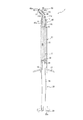
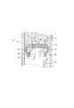
- FIG. 1 is a cross-sectional view showing a configuration of a dispenser 1 according to the first embodiment of the present invention
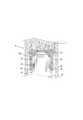
- FIG. 2 is an enlarged cross-sectional view of a tip portion of a plunger 20 and a piston 30 portion.
- the dispenser 1 shown in FIG.1 and FIG.2 shows the state of the dispenser just before a user uses.
- the dispenser 1 has a cylindrical main body 10 that has a cylindrical shape whose front end and rear end are open, and a content C in the filling space M that is slid in the syringe main body 10 through the front end opening 11a.
- a plunger 20 to be dispensed, a piston 30 formed of an elastic member attached to a distal end portion of the plunger 20, and a cap 60 covering the distal end opening 11a of the syringe body 10 are provided.
- the side where the cap 60 described later is located is the front end side (the upper side in FIG. 1)
- the side where the flange 29 of the plunger 20 is located is the rear end side. (Lower side in FIG. 1).
- the syringe body 10 forms a filling space M of the contents C inside the body portion 15, and the distal end cylindrical portion 11 is provided with a distal end opening 11 a. Further, a male threaded portion 11b for fixing a cap 60 or a nozzle 40, which will be described later, by screw engagement is provided on the outer peripheral surface of the distal end tubular portion 11. Further, an annular protrusion 19 that protrudes in the inner peripheral direction is provided on the inner peripheral surface in the vicinity of the rear end of the syringe body 10 to prevent the plunger 20 and the piston 30 from falling off. A flange 17 is provided at the rear end of the syringe body 10 to apply a finger when the user pushes the plunger 20. In addition, about the shape of the collar 17, it can be made into polygonal shape in order to prevent rolling when the dispenser 1 is put.
- the plunger 20 is slid in the distal end direction in the syringe body 10 to press the contents C in the filling space M, and the contents C are poured out through the tip opening 11a.
- the plunger 20 is provided with a groove portion 25 that radially contracts and a projecting portion 23 that protrudes in the radial direction at the tip of the rod portion 28 that extends toward the tip opening 11 a. ing. Note that the rod portion 28, the groove portion 25, and the protruding portion 23 all have a gap with the inner peripheral surface of the body portion 15 of the syringe body 10.
- the piston 30 is fixed to the tip of the plunger 20 by engaging the rear end 37 of the piston 30 formed of an elastic material such as rubber with the groove 25.
- the protruding portion 23 is provided with an inclined portion 23a whose diameter decreases toward the distal end direction, and the seal portion 33 moves along the inclined portion 23a to the inner and outer circumferences as will be described later.
- a flange 29 is provided at the rear end of the plunger 20, and the user C pushes the pressing surface 29 a of the flange 29 so that the contents C in the filling space M are poured out.
- thermoplastic resins such as polyolefin, polyester, polyether or polystyrene
- polyolefin material polypropylene (PP), polyethylene (PE), etc.
- polyester materials such as polyethylene terephthalate (PET) and polybutylene terephthalate (PBT)
- polyether materials such as polyoxymethylene (POM)
- polystyrene resins AS And ABS are typical examples, and are appropriately selected according to the use and contents C.
- the piston 30 is formed of an elastic member such as rubber, and as shown in FIG. 2, as shown in FIG. 2, a ring-shaped seal portion 33 that forms a gap G with the inner peripheral surface of the syringe body 10, and an inner periphery of the seal portion 33
- a front end wall 31 that covers the surface from the front end side, a side wall 35 that extends in the rear end direction from the seal portion 33 along the body portion 15, and an inner periphery for engaging the groove portion 25 to fix the piston 30 to the plunger 20. It has a rear end portion 37 protruding in the direction and a sliding rib 39 that slides on the inner peripheral surface of the syringe body 10.
- a gap G is formed between the outer peripheral surface of the seal portion 33 of the piston 30 and the inner peripheral surface of the syringe body 10.
- the seal portion 33 is not substantially in contact with the inner peripheral surface of the syringe body 10 over the entire outer peripheral surface. Further, the seal portion 33 is in contact with an inclined portion 23 a provided on the protruding portion 23 of the plunger 20.
- the piston 30 covers the protruding portion 23 of the plunger 20 as a whole.
- the sliding rib 39 is provided so that the diameter of the outer peripheral surface thereof is slightly larger than the diameter of the inner peripheral surface of the syringe body 10. Therefore, in a state where the plunger 20 and the piston 30 are inserted into the filling space M of the syringe body 10, the sliding rib 39 is elastically deformed in the inner circumferential direction according to the inner circumferential surface of the syringe body 10, and the syringe body 10 A pressing force is applied to the inner peripheral surface of the. Due to this pressing force, an axial frictional force acts between the syringe body 10 and the piston 30. Therefore, for example, as shown in FIG.
- the sliding rib 39 (sliding part) should just be provided intermittently in the circumferential direction, and the number of ribs and the space
- annular protrusion 19 On the inner peripheral surface in the vicinity of the rear end of the syringe body 10, an annular protrusion 19 that protrudes in the inner peripheral direction is provided. Even when the plunger 20 is intentionally pulled out in the rear end direction or when a predetermined frictional force does not act between the sliding rib 39 and the inner peripheral surface of the syringe body 10, the piston 20 is provided on the piston 30. Since the sliding rib 39 engages with the annular protrusion 19 undercut, the plunger 20 does not move further in the rear end direction, and can be reliably prevented from falling off the syringe body 10.
- the annular protrusion 19 may be provided at a plurality of locations in the circumferential direction so as to be separated from each other.
- the shapes of the plunger 20 and the piston 30 are not limited to the above-described embodiments, and any shape that reduces the gap G when the plunger 20 pushes the contents C in the filling space M is adopted. can do.
- the material of the piston 30 includes silicon rubber, synthetic rubber, butyl rubber, fluorine rubber, and the like, and is appropriately selected. However, it is preferable that the piston 30 is formed of silicon rubber in view of content resistance.
- the cap 60 is a member attached to close the tip opening 11a of the syringe body 10.
- a female screw part 61 a is provided on the inner peripheral surface of the cap side wall 61, and the cap 60 is fixed to the distal end of the syringe main body 10 by being screw-engaged with the male screw part 11 b of the syringe main body 10.
- a cap rib 63 protruding in the outer peripheral direction is provided on the outer peripheral surface of the cap side wall 61, and a user or the like can easily attach and detach the cap 60 to and from the syringe body 10 by grasping the cap rib 63. be able to.
- thermoplastic resins such as polyolefin, polyester, polyether, or polystyrene can be employed.
- the manufacturer In order to pour out the contents C from the dispenser 1 shown in FIGS. 1 and 2, the manufacturer first fills the contents C in the filling space M of the syringe body 10 as a preparation stage. Next, the manufacturer pushes the plunger 20 toward the distal end of the syringe 20 with the cap 60 removed from the syringe body 10. After the manufacturer starts pushing the plunger 20, when the piston 30 is not yet in contact with the contents C in the filling space M, a gap G is formed between the seal portion 33 and the inner peripheral surface of the syringe body 10. Exists. Therefore, since the air in the filling space M escapes in the rear end direction via the gap G, the manufacturer can push the plunger 20 in the front end direction without great resistance.
- the manufacturer brings the seal portion 33 and the tip wall 31 of the piston 30 into contact with the contents C by pushing the plunger 20.
- the piston 30 receives a reaction force from the contents C and the gap G becomes smaller (the reason why the gap G changes will be described in detail later). There is no leakage.
- the manufacturer may further confirm that the piston 30 is in contact with the contents C by pushing the plunger 20 further and slightly discharging the contents C from the opening 11a.
- the piston 30 loses the pressing force from the plunger 20 and receives no reaction force from the contents C, so the gap G is in its original state (the state shown in FIG. 2). Restore to.
- the positive pressure in the filling space M is released and the contents C do not leak from the tip opening 11a.
- the manufacturer implements the preparation steps so far so that the user can use the device, and then attaches the cap 60 to the syringe body 10 to close the tip opening 11a. Then, the dispenser 1 is packed and shipped to the user.
- the user removes the cap 60 of the dispenser 1 that can be used after the above preparation stage is implemented, and instead attaches the nozzle 40 for discharging the contents C.
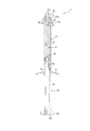
- a state where the nozzle 40 is mounted is shown in FIG.
- a nozzle lid 50 is provided at the tip of the nozzle 40.
- the dispenser with the nozzle 40 attached is labeled 1 '.
- the nozzle 40 guides the contents C from the tip opening 11a of the syringe body 10 in a predetermined direction at the bent portion 43, and then guides the contents C to the outside through the nozzle tube portion 45 through the nozzle opening 45a provided at the tip.
- the nozzle 40 can be configured, for example, as a needle tip as shown in FIG.
- a nozzle cap 41 is provided on the rear end side of the nozzle 40, and by engaging the female screw portion 41a provided on the inner peripheral surface of the nozzle cap 41 with the male screw portion 11b of the syringe body 10, The nozzle 40 is fixed to the tip of the syringe body 10.
- the nozzle lid 50 covers the nozzle opening 45a when the dispenser 1 'is not in use and shields the contents C from light, and prevents foreign matter from entering.
- the nozzle lid 50 has a protrusion 51 a on the inner peripheral surface of the side wall 51, and engages the nozzle 40 by undercut engagement with a protrusion 45 b provided on the outer peripheral surface of the nozzle cylinder 45 of the nozzle 40. Fixed.
- the user In order to pour out the contents C, the user first holds the protrusion 55 provided at the rear end of the nozzle lid 50 and removes the nozzle lid 50 from the dispenser 1 ′. Then, for example, the pressing surface 29a of the plunger 20 is pressed with the thumb while the index finger and the middle finger are put on the flange 17 of the syringe body 10, and the plunger 20 is pushed into the syringe body 10 in the distal direction. At this stage, the seal portion 33 and the tip wall 31 of the piston 30 are already in contact with the contents C.
- the ring-shaped seal portion 33 of the piston 30 moves relative to the plunger 20 in the rear end direction while abutting against the inclined portion 23a by the reaction force from the contents C. .
- the seal portion 33 since the seal portion 33 receives the force in the outer peripheral direction from the inclined portion 23a, the seal portion 33 extends in the outer peripheral direction against the elastic force of the tip wall 31 as shown in FIG. Thereby, the gap G between the seal portion 33 and the inner peripheral surface of the syringe body 10 is reduced, and the gap G is zero in the example shown in FIG.
- the air in the filling space M and the contents C can no longer escape toward the rear end, and a positive pressure is generated in the filling space M. To do. Due to the positive pressure in the filling space M, the contents C are poured out through the tip opening 11 a of the tip tube portion 11 and the nozzle opening 45 a of the nozzle tube portion 45.
- nozzle 40 various thermoplastic resins such as polyolefin, polyester, polyether, or polystyrene can be used. Instead, a nozzle having a tip portion made of metal, glass, ceramics, or the like can be used. It is also possible to adopt. Further, instead of the nozzle 40 shown in FIG. 3, for example, a metal nozzle having a small diameter may be employed.
- the opening located at the foremost end when the content C is poured out is the final pouring hole, and in this embodiment, the nozzle opening 45a of the nozzle 40 is the final pouring hole. . Therefore, in the case where the nozzle 40 is not mounted, the tip opening 11a of the syringe body 10 is the final dispensing hole.
- the ratio of the area of the gap G between the seal portion 33 and the inner peripheral surface of the syringe body 10 when the plunger 20 is pushed to the area of the final dispensing hole is defined as the rear leakage risk.
- the content C that has been subjected to pressure is easily discharged from the final pouring hole having a large area, that is, the nozzle opening 45a. And by the reduction
- FIG. Further, when the plunger 20 and the piston 30 are set in the syringe body 10, there is no gap G between the piston 30 and the syringe body 10, and the plunger 20 is not sealed, so that a large frictional resistance is not applied to the plunger 20. It can be pushed in with a small force.
- the gap G between the seal portion 33 and the inner peripheral surface of the syringe body 10 is in the original state shown in FIG. 2 due to the restoring force of the piston 30 that is an elastic body. Restore to. Accordingly, when the pushing of the plunger 20 is stopped after the content C is poured out, the positive pressure in the filling space M is quickly released through the gap G. As a result, the content C can be prevented from leaking from the nozzle opening 45a due to the residual pressure in the filling space M after the plunger 20 is stopped from being pressed.
- the plunger 20 and the piston 30 are mounted on the syringe body 10 after the syringe body 10 is filled with the contents C, the plunger 20 is released while allowing the air in the filling space M to escape in the rear end direction through the gap G.
- the piston 30 can be easily mounted without great resistance.
- the needle tip as the nozzle 40 so as to pour out the contents C, it is possible to pour out the contents C in an optimum manner according to the liquid quality, use and the like of the contents C.
- the opening at the tip of the needle tip is the final dispensing hole.
- the content C is preferably a paste-like material having a certain degree of viscosity because the effects of the present invention are more remarkably exhibited.
- the consistency of the content C is preferably 60 mm or less, more preferably 50 mm or less, further preferably 40 mm or less, 30 mm or less, 20 mm or less, It may be 15 mm or less.
- the consistency refers to the content (C) left at 25 ° C. for 2 hours in a constant temperature room at 25 ° C.
- the glass plate is removed after standing for 30 seconds, and the arithmetic mean value when the major axis and minor axis of the expanded contents C are measured is meant.
- the major axis is the longest diameter among the diameters passing through the center of the expanded contents C
- the minor axis is the diameter perpendicular to the major axis among the diameters passing through the center of the expanded contents C.
- the Shore hardness of the rubber material constituting the piston 30 according to JIS K 6253 Type A durometer was set to 30 or more and 80 or less. Accordingly, the gap G can be effectively reduced by the reaction force from the contents C in the filling space M with respect to the pressing of the plunger 20 to suppress the leakage of the contents C in the rear end direction. By stopping the pressing, the gap G can be quickly restored, the residual pressure in the filling space M can be released, and leakage of the contents C from the nozzle openings 45a can be suppressed.
- the configuration of the piston 30 is not limited to this mode.
- drum 15 of the syringe main body 10 with respect to the area of the nozzle opening 45a which is the last pouring hole is defined as an area ratio
- area ratio (syringe inner cross-sectional area / final pouring hole) (Area) was configured to be 20 or less.
- the ratio of the dispensing speed of the contents C from the nozzle hole 45a to the pushing speed of the plunger 20 becomes a predetermined value or less. Therefore, the leakage of the contents C from the nozzle opening 45a after stopping the pushing of the plunger 20 can be more reliably suppressed.
- the configurations of the syringe body 10 and the nozzle 40 are not limited to this mode.
- the piston 30 is deformed so that the gap G is reduced by pushing the plunger 20 and the rear leakage risk becomes 0 or more and less than 1, so when the content C is poured out , Leakage in the rear end direction of the contents C can be suppressed. Further, after the pressing of the plunger 20 is stopped, the residual pressure in the filling space M is released by the restoration of the gap G, and the leakage of the contents C from the nozzle opening 45a can be suppressed. In addition, when the plunger 20 and the piston 30 are attached to the syringe body 10 after the syringe body 10 is filled with the contents C, the syringe body 10 can be easily attached without great resistance.
- the needle tip can be attached to the tip, it can be poured out in an optimum manner according to the liquid quality of the contents C, the use and the like.
- the gap G is effectively reduced and the content in the rear end direction is reduced. Leakage of the object C can be suppressed. Moreover, the residual pressure in the filling space M can be quickly released by stopping the pressing of the plunger 20, and leakage of the contents C from the nozzle opening 45a can be suppressed.
- the ratio (area ratio) of the cross-sectional area inside the body portion 15 of the syringe body 10 with respect to the area of the nozzle opening 45a is set to 20 or less. The leakage of the contents C from the nozzle opening 45a can be suppressed more reliably.
- the plunger 20 is intentionally pulled out in the rear end direction. Even when a predetermined frictional force does not act between the sliding rib 39 and the inner peripheral surface of the syringe body 10, the sliding rib 39 provided on the piston 30 engages with the annular protrusion 19 undercut. Thus, it is possible to reliably prevent the plunger 20 and the piston 30 from falling off the syringe body 10.
- FIG. 5 is a cross-sectional view showing the configuration of the dispenser 2 according to the second embodiment of the present invention.
- the dispenser 2 according to the second embodiment is different from the first embodiment in the first embodiment except that the sliding ribs 26 are provided on the plunger 20 ′ instead of the sliding ribs 39 on the piston 30. There is no difference from the form. Therefore, here, the description will focus on the differences from the first embodiment.
- the plunger 20 ' is slid in the distal direction in the syringe body 10', presses the content C in the filling space M, and dispenses the content C through the distal opening 11a.
- the plunger 20 ′ is provided with a sliding protrusion 26 that protrudes in the outer circumferential direction at the tip of a rod portion 28 that extends toward the tip opening 11 a.
- the sliding protrusions 26 are spaced apart from each other at a plurality of locations in the circumferential direction.
- the sliding protrusion 26 is provided so that the diameter of the outer peripheral surface thereof is slightly larger than the diameter of the inner peripheral surface of the syringe body 10 ′.
- the sliding protrusion 26 is elastically deformed in the inner circumferential direction in accordance with the inner circumferential surface of the syringe body 10 ′, and the syringe body.
- a pressing force is applied to the inner peripheral surface of 10 '. Due to this pressing force, an axial frictional force acts between the syringe body 10 'and the plunger 20'. Therefore, for example, as shown in FIG.
- the sliding protrusion 26 should just be provided intermittently in the circumferential direction, and the number of protrusions and the space
- FIG. 6 is a cross-sectional view showing the configuration of the dispenser 3 according to the third embodiment of the present invention
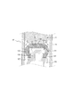
- FIG. 7 is an enlarged cross-sectional view of the tip portion of the plunger 120 and the piston 130 portion.
- the dispenser 3 shown in FIG.6 and FIG.7 shows the state of the dispenser just before a user uses.
- the dispenser 3 according to the third embodiment is not different from the second embodiment except that the distal end shape of the plunger 120 and the shape of the piston 130 are different from those of the second embodiment. Therefore, here, the description will focus on the differences from the second embodiment.
- the plunger 120 is slid in the distal direction in the syringe body 10 'to press the content C in the filling space M, and the content C is poured out through the distal opening 11a.
- the plunger 120 is provided with a groove portion 125 that radially decreases in diameter and a protruding portion 123 that protrudes in the radial direction at the tip of the rod portion 128 that extends toward the tip opening 11 a.
- the piston 130 is fixed to the tip of the plunger 120 by engaging the rear end 137 of the piston 130 formed of an elastic material such as rubber with the groove 125.
- a flange 129 is provided at the rear end of the plunger 120, and the user C pushes the pressing surface 129 a of the flange 129 so that the contents C in the filling space M are poured out.
- the piston 130 is made of an elastic material such as rubber. As shown in FIG. 7, the piston 130 has a shape in which the outer peripheral surface is convex in the outer peripheral direction, and forms a gap G ′ with the inner peripheral surface of the syringe body 10 ′, and the tip of the side wall 133. And a rear end portion 137 that is connected to the rear end side of the side wall 133 and engages with the groove portion 125 to fix the piston 130 to the plunger 120.
- a gap G ′ is formed between the outer peripheral surface of the side wall 133 of the piston 130 and the inner peripheral surface of the syringe body 10 ′.
- the piston 130 has covered the protrusion part 123 of the plunger 120 as a whole.
- the manufacturer fills the contents C in the filling space M of the syringe body 10 '.
- the manufacturer pushes the plunger 120 toward the distal end of the syringe body 10 ′ with the cap 60 removed from the syringe body 10 ′.
- the gap G is formed between the side wall 133 and the inner peripheral surface of the syringe body 10 '. 'Is present.
- the manufacturer can push the plunger 120 in the front end direction without great resistance. Then, the manufacturer brings the tip wall 131 of the piston 130 into contact with the contents C by pushing the plunger 120 in the tip direction. When the plunger 120 is further pushed, the piston 130 receives a reaction force from the contents C, and the gap G 'is reduced, so that the contents C do not leak toward the rear end. Note that the manufacturer may further confirm that the piston 130 is in contact with the content C by pushing the plunger 120 further and slightly discharging the content C from the tip opening 11a.
- the piston 130 loses the pressing force from the plunger 120 and receives no reaction force from the contents C, so that the gap G ′ is in its original state (the state shown in FIG. 7). ) To restore. Therefore, the positive pressure in the filling space M is released and the contents C do not leak from the tip opening 11a.
- the manufacturer performs the preparatory steps so far so that the user can use the device, and then attaches the cap 60 to the syringe body 10 'to close the tip opening 11a. Then, the dispenser 3 is packed and shipped to the user.
- the user removes the cap 60 of the dispenser 3 which can be used after the above preparation stage is implemented, and instead attaches the nozzle 40 for discharging the contents C.
- This state is shown in FIG.
- a nozzle lid 50 is provided at the tip of the nozzle 40.
- 3 ' is attached
- the user In order to pour out the contents C, the user removes the nozzle lid 50 from the dispenser 3 ′, then presses the pressing surface 129a of the plunger 120, and moves the plunger 120 in the distal direction with respect to the syringe body 10 ′. Push into. At this stage, the side wall 133 and the tip wall 131 of the piston 130 are already in contact with the contents C. Therefore, when the plunger 120 is further pushed, the tip wall 131 of the piston 130 receives a reaction force from the contents C and moves relative to the plunger 120 in the rear end direction as shown in FIG. To contact the tip of the plunger 120.
- the upper end of the side wall 133 is displaced in the rear end direction due to the movement of the front end wall 131, while the rear end of the side wall 133 is restricted from being displaced in the rear end direction by the rear end portion 137 contacting the stepped portion 127. It does not move because it is. Therefore, the side wall 133 having a convex shape in the outer peripheral direction is further displaced in the outer peripheral direction, and the gap G ′ between the side wall 133 and the inner peripheral surface of the syringe body 10 ′ is reduced. In particular, in the example shown in FIG. 9, the gap G ′ is zero.
- the air in the filling space M and the contents C can no longer escape toward the rear end, and a positive pressure is generated in the filling space M. appear. Due to the positive pressure in the filling space M, the contents C are poured out through the tip opening 11a of the tip tube portion 11 and the nozzle hole 45a of the nozzle tube portion 45.
- the outer peripheral surface of the side wall 133 has a shape that is convex in the outer peripheral direction.
- the present invention is not limited to this mode.
- the inner peripheral surface of the side wall 133 is convex in the outer peripheral direction. You may have.
- both the outer peripheral surface and the inner peripheral surface of the side wall 133 may have a shape that is convex in the outer peripheral direction.
- the restoring force of the piston 130 restores the gap G ′ between the side wall 133 and the inner peripheral surface of the syringe body 10 ′ to the original state shown in FIG. To do. Accordingly, when the pushing of the plunger 120 is stopped after the content C is poured out, the positive pressure in the filling space M is quickly released through the gap G ′. Accordingly, it is possible to prevent the content C from leaking out of the nozzle opening 45a due to the residual pressure in the filling space M after the pressing of the plunger 120 is stopped.
- the gap G ′ is provided between the inner peripheral surface of the syringe body 10 ′ and the side wall 133 of the piston 130, and the piston 130 is pushed by the plunger 120 and the gap G ′. Deforms to decrease.
- the rear leakage risk which is the ratio of the area of the gap G ′ after deformation of the piston 130 to the area of the nozzle opening 45a (final dispensing hole), is preferably less than 1, and in the present embodiment, particularly 0. Configured.
- the gap G ′ is restored to the original state, and the positive pressure in the filling space M is quickly released through the gap G ′. Accordingly, it is possible to prevent the content C from leaking out of the nozzle opening 45a due to the residual pressure in the filling space M after the pressing of the plunger 120 is stopped. Further, when the plunger 120 and the piston 130 are mounted on the syringe body 10 ′ after the syringe body 10 ′ is filled with the contents C, the air in the filling space M is released to the rear end direction through the gap G ′. The plunger 120 and the piston 130 can be easily mounted without great resistance.
Landscapes
- Engineering & Computer Science (AREA)
- Mechanical Engineering (AREA)
- Health & Medical Sciences (AREA)
- Life Sciences & Earth Sciences (AREA)
- Dentistry (AREA)
- Epidemiology (AREA)
- Oral & Maxillofacial Surgery (AREA)
- Animal Behavior & Ethology (AREA)
- General Health & Medical Sciences (AREA)
- Public Health (AREA)
- Veterinary Medicine (AREA)
- Dental Tools And Instruments Or Auxiliary Dental Instruments (AREA)
- Coating Apparatus (AREA)
- Containers And Packaging Bodies Having A Special Means To Remove Contents (AREA)
- Infusion, Injection, And Reservoir Apparatuses (AREA)
Abstract
Priority Applications (6)
| Application Number | Priority Date | Filing Date | Title |
|---|---|---|---|
| EP17820356.8A EP3479909A4 (fr) | 2016-06-30 | 2017-06-30 | Distributeur |
| JP2018525318A JP6830484B2 (ja) | 2016-06-30 | 2017-06-30 | ディスペンサー |
| AU2017287534A AU2017287534A1 (en) | 2016-06-30 | 2017-06-30 | Dispenser |
| CA3027912A CA3027912A1 (fr) | 2016-06-30 | 2017-06-30 | Distributeur |
| US16/311,151 US10857563B2 (en) | 2016-06-30 | 2017-06-30 | Dispenser |
| CN201780037796.XA CN109311044A (zh) | 2016-06-30 | 2017-06-30 | 分配器 |
Applications Claiming Priority (2)
| Application Number | Priority Date | Filing Date | Title |
|---|---|---|---|
| JP2016129919 | 2016-06-30 | ||
| JP2016-129919 | 2016-06-30 |
Publications (1)
| Publication Number | Publication Date |
|---|---|
| WO2018004002A1 true WO2018004002A1 (fr) | 2018-01-04 |
Family
ID=60785356
Family Applications (1)
| Application Number | Title | Priority Date | Filing Date |
|---|---|---|---|
| PCT/JP2017/024251 Ceased WO2018004002A1 (fr) | 2016-06-30 | 2017-06-30 | Distributeur |
Country Status (7)
| Country | Link |
|---|---|
| US (1) | US10857563B2 (fr) |
| EP (1) | EP3479909A4 (fr) |
| JP (1) | JP6830484B2 (fr) |
| CN (1) | CN109311044A (fr) |
| AU (1) | AU2017287534A1 (fr) |
| CA (1) | CA3027912A1 (fr) |
| WO (1) | WO2018004002A1 (fr) |
Cited By (2)
| Publication number | Priority date | Publication date | Assignee | Title |
|---|---|---|---|---|
| JP2019112126A (ja) * | 2017-12-26 | 2019-07-11 | 小林製薬株式会社 | 押出器具 |
| JP2021525589A (ja) * | 2018-05-30 | 2021-09-27 | ズルツァー ミクスパック アーゲーSulzer Mixpac AG | ディスペンサー・アッセンブリ |
Families Citing this family (8)
| Publication number | Priority date | Publication date | Assignee | Title |
|---|---|---|---|---|
| EP4613387A3 (fr) | 2018-09-19 | 2025-11-19 | PRC-Desoto International, Inc. | Ensembles tête de piston expansible pour pistolets de distribution de produit d'étanchéité |
| US11654453B1 (en) * | 2019-07-09 | 2023-05-23 | Jacob Burns | Roof coating applicator |
| WO2021131327A1 (fr) * | 2019-12-24 | 2021-07-01 | 株式会社スリーボンド | Dispositif d'application de matière et élément de pression |
| WO2022081417A1 (fr) * | 2020-10-13 | 2022-04-21 | Prc-Desoto International, Inc. | Plongeurs pour cartouches de distribution de produit d'étanchéité ayant un emballage de produit d'étanchéité pliable |
| JP6984052B1 (ja) * | 2021-02-05 | 2021-12-17 | 田中貴金属工業株式会社 | 充填済み容器及び気泡混入抑制方法 |
| CN113499965A (zh) * | 2021-06-04 | 2021-10-15 | 华南理工大学 | 一种可控涂布量的线棒涂布器 |
| US20250288492A1 (en) * | 2022-04-29 | 2025-09-18 | Medical International Technologies (Mit Canada) Inc. | Vial adapter and injector assembly for a needle-free injector |
| EP4759437A1 (fr) * | 2024-12-16 | 2026-06-17 | medmix Switzerland AG | Piston |
Citations (6)
| Publication number | Priority date | Publication date | Assignee | Title |
|---|---|---|---|---|
| JPS5817862A (ja) * | 1981-05-16 | 1983-02-02 | ウール ディベロップメント インターナショナル リミテッド | 液体塗布器 |
| JPS60151020A (ja) * | 1984-01-20 | 1985-08-08 | Matsushita Electric Works Ltd | 粘稠剤の押出装置 |
| JP2005237780A (ja) * | 2004-02-27 | 2005-09-08 | Top:Kk | 化粧品用容器 |
| JP2009240427A (ja) * | 2008-03-28 | 2009-10-22 | Terumo Corp | 塗布具 |
| JP2010142573A (ja) * | 2008-12-22 | 2010-07-01 | Coki Engineering Inc | シリンジ用ガスケット及びその製造方法並びに該ガスケットを用いたプレフィルドシリンジ |
| JP2011115585A (ja) * | 2009-12-04 | 2011-06-16 | Firma Ivoclar Vivadent Ag | 塗布デバイス |
Family Cites Families (18)
| Publication number | Priority date | Publication date | Assignee | Title |
|---|---|---|---|---|
| US4266557A (en) * | 1978-01-16 | 1981-05-12 | The Kendall Company | Low friction syringe |
| US4215701A (en) * | 1978-08-21 | 1980-08-05 | Concord Laboratories, Inc. | Elastomeric plunger tip for a syringe |
| JPS5918427B2 (ja) * | 1979-10-09 | 1984-04-27 | テルモ株式会社 | シリンジ用ガスケツト |
| US4543093A (en) * | 1982-12-20 | 1985-09-24 | Becton, Dickinson And Company | Variable sealing pressure plunger rod assembly |
| DE3405547A1 (de) * | 1984-02-16 | 1985-08-14 | Hilti Ag, Schaan | Auspresskolben fuer behaelter |
| US4907727A (en) * | 1988-10-31 | 1990-03-13 | Illinois Tool Works, Inc. | Dispensing device having improved plunger assemblies |
| US5314416A (en) * | 1992-06-22 | 1994-05-24 | Sherwood Medical Company | Low friction syring assembly |
| US6142977A (en) * | 1996-10-18 | 2000-11-07 | Schering Ag | Prefilled, sterilized syringe with a new and improved plug |
| WO1998020920A2 (fr) * | 1996-11-12 | 1998-05-22 | Medrad, Inc. | Seringues preremplissables, et pistons et injecteurs convenant a de telles seringues |
| JP2001057987A (ja) | 1999-08-20 | 2001-03-06 | Gc Corp | 歯科用粘性材料用容器の押出し部構造 |
| US8740856B2 (en) * | 2007-06-04 | 2014-06-03 | Becton, Dickinson And Company | Stoppers used in pre-filled syringes |
| US8418891B1 (en) * | 2007-12-19 | 2013-04-16 | Edison Nation, Llc | Powered dispenser with interchangeable cartridges |
| US8613730B2 (en) * | 2008-11-26 | 2013-12-24 | Acist Medical Systems, Inc. | Apparatus and methods for fluid pressurizing units of injection systems |
| US8955714B1 (en) * | 2012-03-20 | 2015-02-17 | The Boeing Company | Portable cleco type fastener dispenser |
| US9144818B2 (en) * | 2013-03-13 | 2015-09-29 | Illinois Tool Works Inc. | Method and apparatus for dispensing a viscous material on a substrate |
| CN103784071B (zh) * | 2014-01-23 | 2016-06-15 | 金红叶纸业集团有限公司 | 分配器及应用该分配器的系统 |
| US9286557B2 (en) * | 2014-03-06 | 2016-03-15 | International Business Machines Corporation | Optimizing quick response code capacity using gray luminance |
| US10196196B2 (en) * | 2014-09-11 | 2019-02-05 | Vcxt, Llc | Watertight liquid dispenser with syringe-like functions |
-
2017
- 2017-06-30 CA CA3027912A patent/CA3027912A1/fr not_active Abandoned
- 2017-06-30 CN CN201780037796.XA patent/CN109311044A/zh active Pending
- 2017-06-30 WO PCT/JP2017/024251 patent/WO2018004002A1/fr not_active Ceased
- 2017-06-30 US US16/311,151 patent/US10857563B2/en not_active Expired - Fee Related
- 2017-06-30 EP EP17820356.8A patent/EP3479909A4/fr not_active Withdrawn
- 2017-06-30 JP JP2018525318A patent/JP6830484B2/ja active Active
- 2017-06-30 AU AU2017287534A patent/AU2017287534A1/en not_active Abandoned
Patent Citations (6)
| Publication number | Priority date | Publication date | Assignee | Title |
|---|---|---|---|---|
| JPS5817862A (ja) * | 1981-05-16 | 1983-02-02 | ウール ディベロップメント インターナショナル リミテッド | 液体塗布器 |
| JPS60151020A (ja) * | 1984-01-20 | 1985-08-08 | Matsushita Electric Works Ltd | 粘稠剤の押出装置 |
| JP2005237780A (ja) * | 2004-02-27 | 2005-09-08 | Top:Kk | 化粧品用容器 |
| JP2009240427A (ja) * | 2008-03-28 | 2009-10-22 | Terumo Corp | 塗布具 |
| JP2010142573A (ja) * | 2008-12-22 | 2010-07-01 | Coki Engineering Inc | シリンジ用ガスケット及びその製造方法並びに該ガスケットを用いたプレフィルドシリンジ |
| JP2011115585A (ja) * | 2009-12-04 | 2011-06-16 | Firma Ivoclar Vivadent Ag | 塗布デバイス |
Non-Patent Citations (1)
| Title |
|---|
| See also references of EP3479909A4 * |
Cited By (3)
| Publication number | Priority date | Publication date | Assignee | Title |
|---|---|---|---|---|
| JP2019112126A (ja) * | 2017-12-26 | 2019-07-11 | 小林製薬株式会社 | 押出器具 |
| JP7036588B2 (ja) | 2017-12-26 | 2022-03-15 | 小林製薬株式会社 | 押出器具 |
| JP2021525589A (ja) * | 2018-05-30 | 2021-09-27 | ズルツァー ミクスパック アーゲーSulzer Mixpac AG | ディスペンサー・アッセンブリ |
Also Published As
| Publication number | Publication date |
|---|---|
| EP3479909A4 (fr) | 2020-02-26 |
| US20190176183A1 (en) | 2019-06-13 |
| JPWO2018004002A1 (ja) | 2019-04-25 |
| US10857563B2 (en) | 2020-12-08 |
| EP3479909A1 (fr) | 2019-05-08 |
| AU2017287534A1 (en) | 2019-01-17 |
| JP6830484B2 (ja) | 2021-02-17 |
| CA3027912A1 (fr) | 2018-01-04 |
| CN109311044A (zh) | 2019-02-05 |
Similar Documents
| Publication | Publication Date | Title |
|---|---|---|
| JP6830484B2 (ja) | ディスペンサー | |
| US9309042B2 (en) | Liquid dispensing syringe and method for reducing piston bounce | |
| WO2011148564A1 (fr) | Distributeur de type à cartouche | |
| KR101676784B1 (ko) | 도포기 부착 용기 | |
| US10695776B2 (en) | Dispensing valve for pressure pack | |
| JP2008018351A (ja) | 粘性材料の注出用ディスペンサー | |
| WO2007114121A1 (fr) | Contenant enduisant | |
| US11596937B2 (en) | Dispenser for viscous products | |
| JP6596273B2 (ja) | 塗布容器 | |
| US2872950A (en) | Dispensing device | |
| JP6173890B2 (ja) | 塗布具付容器 | |
| JP2015193983A (ja) | 粘着体の付与方法及び便器用器具 | |
| JP4796910B2 (ja) | 粘性材料の注出用ディスペンサー | |
| JP5745302B2 (ja) | 塗布具付き容器 | |
| JP2026061264A (ja) | ポンプ式吐出器 | |
| JP7638615B2 (ja) | 先細りシリンジ用ピストンとそのシリンジ | |
| US10306968B2 (en) | Container for accommodating a flowable fluid | |
| JP5616129B2 (ja) | カートリッジ式ディスペンサー | |
| JP6189195B2 (ja) | 塗布具付容器 | |
| JP2024159294A (ja) | 塗布容器 | |
| JP2002199929A (ja) | マニキュア用等の容器及びその蓋装置並びに容器本体 | |
| JP2014212917A (ja) | 靴用クリームの塗布装置 | |
| JP2018177330A (ja) | レフィル容器及びこれを用いた塗布容器 | |
| JP2008125640A (ja) | 化粧料容器 | |
| JP2010222013A (ja) | 粘性材料の注出用ディスペンサー |
Legal Events
| Date | Code | Title | Description |
|---|---|---|---|
| ENP | Entry into the national phase |
Ref document number: 2018525318 Country of ref document: JP Kind code of ref document: A |
|
| 121 | Ep: the epo has been informed by wipo that ep was designated in this application |
Ref document number: 17820356 Country of ref document: EP Kind code of ref document: A1 |
|
| ENP | Entry into the national phase |
Ref document number: 3027912 Country of ref document: CA |
|
| NENP | Non-entry into the national phase |
Ref country code: DE |
|
| ENP | Entry into the national phase |
Ref document number: 2017287534 Country of ref document: AU Date of ref document: 20170630 Kind code of ref document: A |
|
| ENP | Entry into the national phase |
Ref document number: 2017820356 Country of ref document: EP Effective date: 20190130 |