WO2018008504A1 - ショベル - Google Patents
ショベル Download PDFInfo
- Publication number
- WO2018008504A1 WO2018008504A1 PCT/JP2017/023873 JP2017023873W WO2018008504A1 WO 2018008504 A1 WO2018008504 A1 WO 2018008504A1 JP 2017023873 W JP2017023873 W JP 2017023873W WO 2018008504 A1 WO2018008504 A1 WO 2018008504A1
- Authority
- WO
- WIPO (PCT)
- Prior art keywords
- release
- alarm
- shovel
- notification
- horn
- Prior art date
- Legal status (The legal status is an assumption and is not a legal conclusion. Google has not performed a legal analysis and makes no representation as to the accuracy of the status listed.)
- Ceased
Links
Images





Classifications
-
- E—FIXED CONSTRUCTIONS
- E02—HYDRAULIC ENGINEERING; FOUNDATIONS; SOIL SHIFTING
- E02F—DREDGING; SOIL-SHIFTING
- E02F9/00—Component parts of dredgers or soil-shifting machines, not restricted to one of the kinds covered by groups E02F3/00 - E02F7/00
- E02F9/26—Indicating devices
- E02F9/261—Surveying the work-site to be treated
-
- B—PERFORMING OPERATIONS; TRANSPORTING
- B60—VEHICLES IN GENERAL
- B60R—VEHICLES, VEHICLE FITTINGS, OR VEHICLE PARTS, NOT OTHERWISE PROVIDED FOR
- B60R1/00—Optical viewing arrangements; Real-time viewing arrangements for drivers or passengers using optical image capturing systems, e.g. cameras or video systems specially adapted for use in or on vehicles
- B60R1/20—Real-time viewing arrangements for drivers or passengers using optical image capturing systems, e.g. cameras or video systems specially adapted for use in or on vehicles
- B60R1/22—Real-time viewing arrangements for drivers or passengers using optical image capturing systems, e.g. cameras or video systems specially adapted for use in or on vehicles for viewing an area outside the vehicle, e.g. the exterior of the vehicle
- B60R1/23—Real-time viewing arrangements for drivers or passengers using optical image capturing systems, e.g. cameras or video systems specially adapted for use in or on vehicles for viewing an area outside the vehicle, e.g. the exterior of the vehicle with a predetermined field of view
-
- E—FIXED CONSTRUCTIONS
- E02—HYDRAULIC ENGINEERING; FOUNDATIONS; SOIL SHIFTING
- E02F—DREDGING; SOIL-SHIFTING
- E02F3/00—Dredgers; Soil-shifting machines
- E02F3/04—Dredgers; Soil-shifting machines mechanically-driven
- E02F3/28—Dredgers; Soil-shifting machines mechanically-driven with digging tools mounted on a dipper- or bucket-arm, i.e. there is either one arm or a pair of arms, e.g. dippers, buckets
- E02F3/36—Component parts
- E02F3/42—Drives for dippers, buckets, dipper-arms or bucket-arms
- E02F3/43—Control of dipper or bucket position; Control of sequence of drive operations
- E02F3/435—Control of dipper or bucket position; Control of sequence of drive operations for dipper-arms, backhoes or the like
-
- E—FIXED CONSTRUCTIONS
- E02—HYDRAULIC ENGINEERING; FOUNDATIONS; SOIL SHIFTING
- E02F—DREDGING; SOIL-SHIFTING
- E02F9/00—Component parts of dredgers or soil-shifting machines, not restricted to one of the kinds covered by groups E02F3/00 - E02F7/00
- E02F9/20—Drives; Control devices
- E02F9/2004—Control mechanisms, e.g. control levers
-
- E—FIXED CONSTRUCTIONS
- E02—HYDRAULIC ENGINEERING; FOUNDATIONS; SOIL SHIFTING
- E02F—DREDGING; SOIL-SHIFTING
- E02F9/00—Component parts of dredgers or soil-shifting machines, not restricted to one of the kinds covered by groups E02F3/00 - E02F7/00
- E02F9/20—Drives; Control devices
- E02F9/2025—Particular purposes of control systems not otherwise provided for
- E02F9/2033—Limiting the movement of frames or implements, e.g. to avoid collision between implements and the cabin
-
- E—FIXED CONSTRUCTIONS
- E02—HYDRAULIC ENGINEERING; FOUNDATIONS; SOIL SHIFTING
- E02F—DREDGING; SOIL-SHIFTING
- E02F9/00—Component parts of dredgers or soil-shifting machines, not restricted to one of the kinds covered by groups E02F3/00 - E02F7/00
- E02F9/24—Safety devices, e.g. for preventing overload
-
- E—FIXED CONSTRUCTIONS
- E02—HYDRAULIC ENGINEERING; FOUNDATIONS; SOIL SHIFTING
- E02F—DREDGING; SOIL-SHIFTING
- E02F9/00—Component parts of dredgers or soil-shifting machines, not restricted to one of the kinds covered by groups E02F3/00 - E02F7/00
- E02F9/26—Indicating devices
-
- E—FIXED CONSTRUCTIONS
- E02—HYDRAULIC ENGINEERING; FOUNDATIONS; SOIL SHIFTING
- E02F—DREDGING; SOIL-SHIFTING
- E02F9/00—Component parts of dredgers or soil-shifting machines, not restricted to one of the kinds covered by groups E02F3/00 - E02F7/00
- E02F9/26—Indicating devices
- E02F9/261—Surveying the work-site to be treated
- E02F9/262—Surveying the work-site to be treated with follow-up actions to control the work tool, e.g. controller
-
- G—PHYSICS
- G08—SIGNALLING
- G08B—SIGNALLING SYSTEMS, e.g. PERSONAL CALLING SYSTEMS; ORDER TELEGRAPHS; ALARM SYSTEMS
- G08B21/00—Alarms responsive to a single specified undesired or abnormal condition and not otherwise provided for
- G08B21/02—Alarms for ensuring the safety of persons
-
- G—PHYSICS
- G08—SIGNALLING
- G08B—SIGNALLING SYSTEMS, e.g. PERSONAL CALLING SYSTEMS; ORDER TELEGRAPHS; ALARM SYSTEMS
- G08B5/00—Visible signalling systems, e.g. visible personal calling systems or remote indication of seats occupied
- G08B5/22—Visible signalling systems, e.g. visible personal calling systems or remote indication of seats occupied using electric transmission; using electromagnetic transmission
- G08B5/36—Visible signalling systems, e.g. visible personal calling systems or remote indication of seats occupied using electric transmission; using electromagnetic transmission using visible light sources
-
- G—PHYSICS
- G08—SIGNALLING
- G08B—SIGNALLING SYSTEMS, e.g. PERSONAL CALLING SYSTEMS; ORDER TELEGRAPHS; ALARM SYSTEMS
- G08B6/00—Tactile signalling systems, e.g. tactile personal calling systems
-
- B—PERFORMING OPERATIONS; TRANSPORTING
- B60—VEHICLES IN GENERAL
- B60R—VEHICLES, VEHICLE FITTINGS, OR VEHICLE PARTS, NOT OTHERWISE PROVIDED FOR
- B60R2300/00—Details of viewing arrangements using cameras and displays, specially adapted for use in a vehicle
- B60R2300/80—Details of viewing arrangements using cameras and displays, specially adapted for use in a vehicle characterised by the intended use of the viewing arrangement
- B60R2300/8033—Details of viewing arrangements using cameras and displays, specially adapted for use in a vehicle characterised by the intended use of the viewing arrangement for pedestrian protection
-
- E—FIXED CONSTRUCTIONS
- E02—HYDRAULIC ENGINEERING; FOUNDATIONS; SOIL SHIFTING
- E02F—DREDGING; SOIL-SHIFTING
- E02F3/00—Dredgers; Soil-shifting machines
- E02F3/04—Dredgers; Soil-shifting machines mechanically-driven
- E02F3/28—Dredgers; Soil-shifting machines mechanically-driven with digging tools mounted on a dipper- or bucket-arm, i.e. there is either one arm or a pair of arms, e.g. dippers, buckets
- E02F3/30—Dredgers; Soil-shifting machines mechanically-driven with digging tools mounted on a dipper- or bucket-arm, i.e. there is either one arm or a pair of arms, e.g. dippers, buckets with a dipper-arm pivoted on a cantilever beam, i.e. boom
- E02F3/32—Dredgers; Soil-shifting machines mechanically-driven with digging tools mounted on a dipper- or bucket-arm, i.e. there is either one arm or a pair of arms, e.g. dippers, buckets with a dipper-arm pivoted on a cantilever beam, i.e. boom working downwardly and towards the machine, e.g. with backhoes
Definitions
- the present invention relates to a shovel capable of detecting an object present in the surroundings.
- the shovel When the shovel detects a person around the shovel, the shovel outputs a warning to the operator of the shovel in the cabin to stop the movement of the shovel. After confirming the surrounding condition, the operator of the shovel presses the alarm stop button displayed on the liquid crystal display to cancel the alarm and resume the movement of the shovel.
- the operator of the shovel may resume the movement of the shovel without notifying the surrounding workers that the shovel starts moving after stopping the alarm sounding in the cabin.
- the alerting to the surrounding workers who are not prepared for the resumption of the operation of the shovel may be insufficient.
- the shovel according to the embodiment of the present invention includes a traveling body, a swing body mounted on the traveling body so as to be able to turn, object detection means for detecting a predetermined object around the shovel, and the object is detected.
- Control means for notifying the operation restriction of the shovel or that the object has been detected, and release means for releasing the operation restriction or the notice, and the release is performed at the time of release by the release means To the surrounding area.
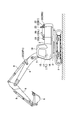
- FIG. 1A is a side view of a shovel
- FIG. 1B is a top view of the shovel
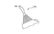
- FIG. 1C is an enlarged side view of the left operation lever 17L in FIG. 1B.
- the upper structure 3 is rotatably mounted on the lower traveling body 1 of the shovel via a turning mechanism 2.
- a boom 4 is attached to the upper swing body 3.
- An arm 5 is attached to the tip of the boom 4, and a bucket 6 is attached to the tip of the arm 5.
- the boom 4, the arm 5 and the bucket 6 are hydraulically driven by the boom cylinder 7, the arm cylinder 8 and the bucket cylinder 9 respectively.
- the upper revolving superstructure 3 is provided with a cabin 10 as a driver's cab and a power source such as an engine.
- a horn 16 In addition, a horn 16, an object detection device 20, a travel alarm 21, a work light 22, a rotation light 23 and the like are attached to the upper revolving superstructure 3.
- the horn 16 is an example of an ambient alarm that outputs sound toward the periphery of the shovel.
- the horn 16 is an electronic horn attached to the upper surface of the upper swing body 3 between the boom 4 and the cabin 10 and mainly outputting sound to a person present in front of the shovel.
- the horn 16 may be another type of horn such as an air horn.
- the horn 16 outputs a sound, for example, when the horn switch 18 is pressed.
- the horn 16 continuously outputs sound while the horn switch 18 is pressed. After the horn switch 18 is pressed, the sound may be output continuously for a predetermined time.
- the horn 16 is used, for example, to signal a driver of a dump truck or to notify a person present around the shovel of the presence of the shovel.
- the object detection device 20 is a device for detecting an object around a shovel.
- the object detection device 20 is, for example, an image sensor for acquiring an image around a shovel.
- the image sensor is configured of an imaging element such as a CCD, a CMOS, etc., for example.
- the image sensor is composed of three monocular cameras mounted on the upper surface of the upper swing body 3 so as to be able to image the blind spot of the operator in the cabin 10.
- the three monocular cameras are the left camera 20L attached to the left end of the upper surface of the upper swing body 3, the right camera 20R attached to the right end of the upper surface of the upper swing body 3, and the upper surface of the upper swing body 3 It is a back camera 20B attached to the rear end.
- the three monocular cameras are desirably attached to the upper swing body 3 so as not to protrude from the upper surface of the upper swing body 3 as shown in FIG. 1B.
- the left camera 20L may be omitted.
- the object detection device 20 may be an ultrasonic sensor, a laser radar sensor, a millimeter wave sensor, a pyroelectric infrared sensor, a bolometer infrared sensor, an infrared camera, or the like.
- the traveling alarm 21 is a voice output device that outputs a voice in conjunction with the traveling of the shovel.
- the traveling alarm 21 outputs a sound toward the periphery of the shovel, for example, when the shovel is traveling.
- the traveling alarm 21 is attached to the lower surface of the upper swing body 3 on the opposite side of the horn 16 across the pivot, and outputs a sound mainly to people present on the side and the rear of the shovel. It is a speaker.
- the traveling alarm 21 outputs a sound when the traveling lever or the traveling pedal is operated.
- the traveling alarm 21 continuously outputs a sound while the traveling lever or the traveling pedal is operated.
- the traveling alarm 21 may output sound continuously while the traveling hydraulic motor is rotating.
- the work light 22 is a light device that illuminates the periphery of the shovel.
- the work light 22 is a first front work light 22F1 attached to the side of the boom 4, a second front work light 22F2 attached to the right front end of the upper swing body 3, a left end of the upper swing body 3
- the work lamp 22 is desirably attached to the upper swing body 3 so as not to protrude from the upper surface of the upper swing body 3 as shown in FIG. 1B. Turning on / off of the work light 22 is switched, for example, using a work light switch installed in the cabin 10. Lighting and extinguishing of each work light may be switched separately, and lighting and extinguishing of a plurality of work lights may be switched collectively. In addition, lighting and extinguishing of the work lamp 22 may be automatically switched in accordance with a command from the control device 30.
- the rotating light 23 is a lighting device that uses a light to call attention of a person present around the shovel.
- the rotary light 23 is attached to the upper rear portion of the upper swing body 3 and mainly draws attention of people present on the side and rear of the shovel.
- the turning on / off of the rotary light 23 is switched, for example, using a rotary light switch installed in the cabin 10.
- the turning on / off of the rotary light 23 may be automatically switched in accordance with a command from the control device 30.
- an indoor alarm 15, an operation lever 17, a control device 30, and the like are installed.
- the indoor alarm device 15 is a device for raising the attention of the operator in the cabin 10, and outputs an alarm to the operator in the cabin 10, for example.
- the indoor alarm 15 may be a buzzer, a speaker, a display, an LED lamp, a seat vibrator or the like installed in the cabin 10.
- the alarm is configured of, for example, at least one of a visual alarm, an audible alarm, and a tactile alarm.
- the indoor alarm 15 includes a display.
- the control lever 17 is a device used to operate the shovel.
- the control lever 17 is configured of a left control lever 17L and a right control lever 17R.
- the left control lever 17L is used for opening and closing the arm 5 and left and right pivoting of the upper swing body 3
- the right control lever 17R is used for opening and closing the boom 4 and opening and closing the bucket 6.
- a horn switch 18 is provided at the end of the left operation lever 17L as shown in FIG. 1C.
- the operator of the shovel can press the horn switch 18 with the thumb of the left hand while operating the left control lever 17L with the left hand, back and forth and right and left.
- the horn switch 18 may be provided at another position of the left operation lever 17L, or may be provided at the right operation lever 17R.
- the horn switch 18 is a switch for operating the horn 16.
- the horn 16 is directly connected to the horn switch 18 and is configured to operate continuously while the horn switch 18 is pressed.
- the horn 16 may additionally or alternatively be connected indirectly to the horn switch 18 via the control device 30. In this case, the horn 16 is operable in response to a control command from the controller 30.
- the horn switch 18 is connected to the controller 30.
- This connection may be a wired connection or a wireless connection. Also, it may be analog connection or digital connection.
- the control device 30 outputs a control command to the indoor alarm 15 according to a control command from the horn switch 18, for example, and cancels the alarm by the indoor alarm 15.
- the horn switch 18 may be a hardware button installed at another place in the cabin 10, or may be a software button displayed on the touch panel display.
- the control device 30 is a computer provided with a CPU, a volatile storage device, a non-volatile storage device, and the like.
- the control device 30 generates an output image based on camera images captured by each of the back camera 20B, the left camera 20L, and the right camera 20R. Then, the generated output image is displayed on the in-vehicle display.
- the output image is, for example, a bird's eye image generated by subjecting a composite image of three camera images to viewpoint conversion processing.
- the output image may be a through image of each camera.
- FIG. 2A is a block diagram showing a configuration example of the object detection system 50.
- FIG. 2B is a block diagram showing another configuration example of the object detection system 50.
- FIG. 2A is a block diagram showing a configuration example of the object detection system 50.
- FIG. 2B is a block diagram showing another configuration example of the object detection system 50.
- the object detection system 50 is a system for detecting an object present around a shovel, and mainly includes the indoor alarm 15, the horn 16, the horn switch 18, the object detection device 20, the traveling alarm 21, the work light 22, and the rotating light 23. , And the control device 30 and the like.
- An object is a person, a vehicle, a work machine, an animal or the like. In the present embodiment, the object detection system 50 detects a person.
- control device 30 causes the CPU to execute programs corresponding to the functional elements such as the human detection unit 31 and the alarm release unit 32 to correspond to the respective functional elements. To realize the function.
- the human detection unit 31 is a functional element that detects a person present around the shovel.
- the human detection unit 31 is an example of an object detection unit that detects a predetermined object.
- the human detection unit 31 determines the presence or absence of a human around the shovel based on the output of the human detection means and the image sensor as the object detection device 20.
- the human detection unit 31 detects a human based on the image shape, it is possible to distinguish an object other than human, such as a tree or a building, from a human.
- the human detection unit 31 determines the presence or absence of a person in the vicinity of the shovel, for example, by finding out a human image in a captured image using an image feature amount such as an HOG feature amount.
- the human detection unit 31 may determine the presence or absence of a person around the shovel using other known image recognition techniques.
- the human detection unit 31 is an output of an object detection sensor such as an ultrasonic sensor as a human detection means and the object detection device 20, a laser radar sensor, a millimeter wave sensor, a pyroelectric infrared sensor, a bolometer infrared sensor, or an infrared camera.
- an object detection sensor such as an ultrasonic sensor as a human detection means and the object detection device 20, a laser radar sensor, a millimeter wave sensor, a pyroelectric infrared sensor, a bolometer infrared sensor, or an infrared camera.
- the presence or absence of a person around the shovel may be determined based on For example, when the output of the pyroelectric infrared sensor is used, the human detection unit 31 detects that an object has entered the detection space if the energy change in the predetermined detection space exceeds a predetermined threshold, that is, a person is present. judge.
- the human detection unit 31 When the human detection unit 31 detects a person present around the shovel, the control command is output to the indoor alarm 15 to operate the indoor alarm 15, and the shovel is detected as detecting the person present around the shovel Tell the operator of In the present embodiment, the human detection unit 31 operates a buzzer installed in the cabin 10 to notify the operator of the shovel that a person present around the shovel has been detected.
- An image representing that a person present around the shovel has been detected may be displayed on a display installed in the cabin 10.
- the human detection unit 31 may also display a camera image including the detected human image on the display as an output image.
- an LED lamp may be turned on to indicate that a person present around the shovel has been detected, or the driver's seat or the control lever 17 may be vibrated by a vibrator.
- the movement of the shovel may be stopped by forcibly stopping the engine, or the movement of the shovel may be limited by disabling the operation input via the operation lever 17.
- the instruction may be wirelessly transmitted to a portable device such as a mobile phone, a smartphone, a buzzer or the like held by the operator of the shovel, and the portable device may output at least one of sound, display, light and vibration.
- the alarm cancellation unit 32 is a functional element that cancels an alarm.
- the alarm cancellation unit 32 cancels the alarm activated by the human detection unit 31 when a predetermined operation is performed. For example, when it is determined that the horn switch 18 is pressed based on the signal from the horn switch 18, the alarm cancellation unit 32 stops the operation of the indoor alarm 15.
- the horn switch 18 directly actuates the horn 16 when depressed. That is, the horn switch 18 can operate the horn 16 independently of the control device 30. However, when the horn 16 is connected to the control device 30 as indicated by the broken line arrow in FIG. 2A, the control device 30 may operate the horn 16 when the horn switch 18 is pressed. In this case, the horn 16 may not be connected to the horn switch 18.
- the shovel or the alarm cancellation unit 32 can operate the horn 16 simultaneously with the cancellation of the alarm by the indoor alarm 15. That is, the operator of the shovel can reliably ring the horn 16 when canceling the alarm. Therefore, when the warning to the operator of the shovel is canceled, the surrounding workers can be surely alerted. And, it is possible to surely inform surrounding workers that the shovel starts moving.
- the alarm cancellation unit 32 may activate an ambient alarm other than the horn 16 when canceling the alarm for the operator of the shovel. When the warning to the operator of the shovel is canceled, it is to be reliably alerted by the surrounding workers.
- the surrounding alarm device is a device that outputs an alarm to a person present around the shovel, and, for example, a traveling alarm 21 attached to the upper swing body 3, a working light 22, and a rotating light 23 besides the horn 16. Etc.
- the alarm release unit 32 stops the operation of the indoor alarm 15, and the travel alarm 21, the work light 22, and The rotary light 23 is operated. At least one of the traveling alarm 21, the work lamp 22, and the rotary lamp 23 may be operated.
- the horn 16 is connected only to the control device 30, that is, when the alarm cancellation unit 32 can control whether to operate the horn 16, the operation of the horn 16 may be omitted. Further, the work lamp 22 may be blinked.
- the alarm cancellation unit 32 may activate the ambient alarm for a predetermined time when the alarm by the indoor alarm 15 is canceled. For example, after stopping the operation of the indoor alarm 15, the alarm release unit 32 may operate the traveling alarm 21, the work light 22, and the rotary light 23 continuously for a predetermined time.
- FIG. 2B is a block diagram showing a configuration example of the object detection system 50 including the alarm release switch 18A.
- FIG. 2C is a view showing the inside of the cabin 10 seen by the operator seated at the driver's seat, and shows an alarm release switch 18A provided near the display which also functions as the indoor alarm 15.
- the alarm release switch 18 ⁇ / b> A is connected to the control device 30 in the same manner as the horn switch 18. This connection may be a wired connection or a wireless connection. Also, it may be analog connection or digital connection. In the example of FIG. 2B, the horn switch 18 may not be connected to the control device 30.
- the control device 30 outputs a control command to the indoor alarm 15 according to the control command from the alarm release switch 18A, and cancels the alarm by the indoor alarm 15.
- the alarm cancellation switch 18A may be a switch only for the purpose of canceling an alarm, or may be a switch such as the horn switch 18 which is usually used for another purpose.
- the alarm cancellation unit 32 operates the horn 16 and stops the operation of the indoor alarm 15.
- another function original function
- the original function may be executed or the execution may be omitted.
- release part 32 may operate
- When operating the ambient alarm at alarm release it may be configured to be able to set as a parameter whether to operate the horn 16 at alarm release.
- the alarm cancellation unit 32 can activate the ambient alarm simultaneously with the cancellation of the alarm by the indoor alarm 15. Therefore, when the warning to the operator of the shovel is canceled, it is possible to more reliably draw the attention of the surrounding workers. And it can be reliably notified by the surrounding workers that the shovel starts moving.
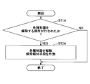
- FIG. 3A is a flowchart of an example of the restriction release process.
- the control device 30 repeatedly executes the restriction releasing process at a predetermined control cycle when various restrictions are performed because an object is detected around the shovel.
- Various restrictions include restricting the movement of the shovel, informing the operator of the shovel that an object has been detected, and the like. Informing the operator of the shovel that an object has been detected includes, for example, continuously sounding an alarm, continuously blinking an LED lamp, and the like.
- the cancellation of the various restrictions includes canceling the operation restriction of the shovel, stopping the alarm, turning off the LED lamp, and the like.
- control device 30 determines whether or not an operation to release various restrictions has been performed (step ST1A).
- the operation for releasing various restrictions includes, for example, pressing the horn switch 18, operating the alarm release switch 18A, and the like.
- control device 30 ends the current limit release process.
- the control device 30 as the release means releases various restrictions and operates the release notification means to notify the execution of the release around the shovel (Step ST2A).
- the release notification unit is a functional element that notifies, for example, the execution of the release by the release unit to the surroundings using at least one of light, sound, display, and vibration.
- control device 30 can operate the release notification unit simultaneously with the release of the various restrictions. That is, the operator of the shovel inevitably operates the release notification means when releasing the various restrictions. Therefore, when various restrictions are removed, it is possible to surely draw the attention of the surrounding workers. And, it is possible to surely inform surrounding workers that the shovel starts moving.
- FIG. 3B is a flowchart of an example of alarm release processing which is a specific example of restriction release processing.
- the control device 30 repeatedly executes the alarm release process at a predetermined control cycle when the indoor alarm 15 is in operation.
- the object detection system 50 detects a person present around the shovel and operates the indoor alarm 15.
- the alarm release unit 32 of the control device 30 determines whether the horn switch 18 has been operated (step ST1B). For example, the alarm cancellation unit 32 determines whether or not the horn switch 18 is pressed based on a signal that the horn switch 18 outputs to the control device 30.
- the alarm release unit 32 ends the current alarm release process.
- the alarm canceling unit 32 cancels the alarm by the indoor alarm 15 (step ST2B). For example, the alarm cancellation unit 32 outputs a control command to the indoor alarm 15 according to the signal from the horn switch 18 to stop the operation of the indoor alarm 15.
- the horn 16 When the horn switch 18 is directly connected to the horn 16, the horn 16 sounds an alarm in response to the depression of the horn switch 18. When the horn switch 18 is indirectly connected to the horn 16 via the control device 30, the horn 16 sounds an alarm in response to a control command from the control device 30.
- the alarm cancellation unit 32 can operate the horn 16 simultaneously with the cancellation of the alarm by the indoor alarm 15. That is, the operator of the shovel inevitably rings the horn 16 when canceling the alarm. Therefore, when the warning to the operator of the shovel is canceled, the surrounding workers can be surely alerted. And, it is possible to surely inform surrounding workers that the shovel starts moving.
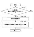
- FIG. 4A is a flowchart of another example of the restriction release process.
- the control device 30 repeatedly executes the restriction releasing process at a predetermined control cycle when various restrictions are performed because an object is detected around the shovel.
- the various restrictions include restricting the movement of the shovel, informing the operator of the shovel that an object has been detected, and the like.
- control device 30 determines whether or not an operation to release various restrictions has been performed (step ST11A).
- control device 30 ends the current limit release process.
- step ST11A If it is determined that the release operation has been performed (YES in step ST11A), the control device 30 releases the various restrictions (step ST12A) and operates the release notification unit for a predetermined time (step ST13A).
- the object detection system 50 can more reliably draw attention of a person present around the shovel by operating the release notification means.
- FIG. 4B is a flowchart of another example of the alarm release process.
- the control device 30 repeatedly executes the alarm release process at a predetermined control cycle when the indoor alarm 15 is in operation.
- the object detection system 50 detects a person present around the shovel and operates the indoor alarm 15.
- the alarm release unit 32 of the control device 30 determines whether the horn switch 18 has been operated (step ST11B).
- the alarm release unit 32 ends the current alarm release process.
- the alarm cancellation unit 32 cancels the alarm by the indoor alarm 15 (step ST12B), and operates the ambient alarm for a predetermined time (step ST13B).
- the alarm cancellation unit 32 outputs a control command to the indoor alarm 15 according to a signal from the horn switch 18 to stop the operation of the indoor alarm 15, and outputs a control instruction to the ambient alarm.
- the ambient alarm is activated for a predetermined time.
- the surrounding alarm includes, for example, a traveling alarm 21, a work light 22, and a rotating light 23.
- the horn 16 When the horn switch 18 is directly connected to the horn 16, the horn 16 sounds an alarm in response to the depression of the horn switch 18. When the horn switch 18 is indirectly connected to the horn 16 via the control device 30, the horn 16 sounds an alarm in response to a control command from the control device 30.
- the alarm cancellation unit 32 can activate the traveling alarm 21 simultaneously with the start of the operation of the horn 16.
- the time to continue the operation of the traveling alarm 21 may be the same as the time to continue the operation of the horn 16, or may be a preset time that is independent of the time to continue the operation of the horn 16.
- the object detection system 50 can call attention of a person who exists mainly in front of the shovel by ringing the horn 16, and mainly exists in the side and rear of the shovel by ringing the traveling alarm 21. Can alert the person who
- the alarm cancellation unit 32 can operate the work lamp 22 simultaneously with the start of operation of the horn 16.
- the alarm release unit 32 may operate all the work lights attached to the upper swing body 3 and may operate only the work lights that illuminate the direction in which the detected person is present.
- the operation of the work light 22 includes blinking (intermittent lighting) of the work light 22.
- the alarm cancellation unit 32 can operate the rotary light 23 simultaneously with the start of operation of the horn 16.
- the time to continue the operation of the work lamp 22 may be the same as the time to continue the operation of the horn 16 or may be a preset time that is independent of the time to continue the operation of the horn 16. The same applies to the rotating light 23.
- the object detection system 50 can mainly draw attention of a person present in front of the shovel by turning on the first front work light 22F1 and the second front work light 22F2, and the first rear work light 22B1 and By turning on the second rear work lamp 22B2, it is possible to draw attention mainly to the person present behind the shovel.
- the left work lamp 22L it is possible to draw attention mainly to the person present on the left of the shovel
- the right work lamp 22R to draw attention to the person present mainly on the right of the shovel. it can.
- the rotary lamp 23 it is possible to draw attention mainly to people present on the side and rear of the shovel.
- the shovel according to the embodiment of the present invention includes the traveling body, the swing body mounted on the traveling body so as to be able to turn, the object detection means for detecting a predetermined object around the shovel, and the object detection Control means for notifying that the operation of the shovel has been detected or that an object has been detected, and a release means for releasing the operation limit or the notification; Alert to
- the predetermined objects include persons such as workers, animals, machines and the like.
- the shovel has the person detection unit 31 that detects a person present around the shovel, but may have an object detection unit that detects a predetermined object other than a person separately from a person Good. That is, the object detection means includes a human detection unit 31, an object detection unit, and the like.
- the control means is realized by the control device 30, for example.
- the notification that an object is detected is a notification to the operator in the cabin 10.
- the alarm output by the indoor alarm 15, the lighting of the LED lamp installed in the cabin 10, the driver's seat or the operation by the vibrator It is realized by the vibration of the lever 17 or the like. It may be realized by an output of at least one of sound, display, light and vibration in a portable device such as a mobile phone, a smartphone, a buzzer and the like held by the operator of the shovel.
- the release means is realized by, for example, the control device 30 (for example, the alarm release unit 32).
- the notification about the release by the release means is a notification to the worker etc. who are around the shovel, and is realized, for example, by the operation of the surrounding alarm as the release notification means.
- the surrounding alarm includes a horn 16, a traveling alarm 21, a work light 22, a rotating light 23, a display panel attached to the upper swing body 3, and the like.
- the notification about the release by the release means may be realized by an output of at least one of sound, display, light and vibration in a portable device held by the operator or the like.
- the release notification unit can notify the surroundings of execution of the release by the release unit using at least one of sound, display, light, and vibration.
- Informing the periphery of the execution of the release means informing the surroundings that the release has been performed or informing the surroundings that the release is about to be performed.
- the shovel according to the embodiment of the present invention notifies the execution of the release to the surroundings when the release means releases, it is possible that the surrounding workers etc. may move the shovel before it starts moving. Can be informed. Therefore, for example, the worker can evacuate before the shovel starts moving, that is, can leave the shovel. As a result, the safety of the workers can be enhanced.
- the shovel which concerns on the Example of this invention may alert
- the shovel which concerns on the Example of this invention may alert
- the means for lighting or blinking the light visible to the person around the shovel may be, for example, a work light 22 attached to the upper swing body 3, a rotating light 23, a display panel, etc. It may be a display panel installed, a lighting device or the like, or a portable device or the like possessed by a worker or the like.
- the shovel which concerns on the Example of this invention may alert
- the sound generation means for generating a sound that can be perceived by the person around the shovel may be, for example, a horn 16 attached to the upper swing body 3, a traveling alarm 21, a speaker, a buzzer, etc., installed at the work site
- the speaker may be a speaker, a buzzer or the like, or a portable device or the like possessed by a worker or the like.
- the shovel according to the embodiment of the present invention is installed in, for example, a cabin 10 as a cab mounted on an upper swing body 3 as a swing body, a surrounding alarm attached to the upper swing body 3, and the cabin 10
- Control device 30 having the indoor alarm 15 as described above, a switch provided in the cabin 10 for canceling the alarm by the indoor alarm 15, and a human detection unit 31 as a human detection function for detecting a person around the shovel And may be provided. Then, when detecting a person around the shovel, the control device 30 starts an alarm by the indoor alarm 15, and when the switch is operated, cancels the alarm by the indoor alarm 15 and operates the ambient alarm at the same time.
- the lighting device attached to the upper swing body 3 is operated for at least a predetermined time.
- the ambient alarm is, for example, a horn 16, the switch is, for example, a horn switch 18, and the lighting devices are, for example, a work light 22, a rotary light 23, and the like.
- the control device 30 operates the traveling alarm 21 attached to the upper swing body 3 as a voice output device that outputs voice in conjunction with traveling. Good.
- the shovel which concerns on the Example of this invention may be equipped with the camera which is an example of the object detection apparatus 20 attached to the revolving super structure 3 and the display as a display apparatus installed in the cabin 10. As shown in FIG. Then, when a person around the shovel is detected, the control device 30 may cause the display to display a camera image captured by a camera and an alarm image indicating that a person is present around the shovel.
- the alarm image is composed of, for example, an icon, text, a symbol and the like.
- the release means (release start means) is preferably provided in the operator's cab so as to be manually operable.
- the release means provided in the cab so as to be manually operable is, for example, a horn switch 18.
- the alarm cancellation switch 18A may be used.
- the release means (release start means) may be connected to the control means, and the control means may be connected to release notification means for notifying the periphery of execution of the release at the time of release by the release means. Then, the control means may release the notification that the operation limitation of the shovel or the object is detected according to the signal from the release means, and may send a signal regarding the notification to the release notification means.
- the alarm release switch 18A as the release means may be connected to the control device 30 as the control means. Then, the control device 30 may be connected to the horn 16 as a release notification means for notifying the periphery of execution of the release when releasing the alarm release switch 18A.
- Control device 30 cancels the notification that the operation of the shovel is restricted or that an object has been detected according to the signal from alarm release switch 18A, and transmits a signal related to the notification to horn 16 to operate horn 16 You may With this configuration, the control device 30 can appropriately adjust the timing at which the operation restriction of the shovel or the notification that the object is detected is released and the timing at which the execution of the release is notified to the surroundings.
- the release can be performed after informing the surroundings that the release is to be performed.
- cancellation and notification to the surroundings can be performed simultaneously.
- it can be notified to the surroundings that the cancellation is performed.
- the release means (release start means) may be connected to the release notification means and control means for notifying the periphery of execution of the release at the time of release by the release means. Then, the control means cancels the notification that the operation restriction of the shovel or the object is detected according to the signal from the releasing means, and the release notifying means takes the execution of the cancellation around according to the signal from the releasing means. You may alert
- the control device 30 cancels the notification that the operation restriction of the shovel or the object is detected according to the signal from the horn switch 18, and the horn 16 operates and cancels according to the signal from the horn switch 18.
- the execution of the event may be informed to the surroundings.
- the horn switch 18 can simultaneously bring about the operation of the horn 16 and the operation restriction of the shovel by the control device 30 or the cancellation of the notification that an object is detected.
- the shovel according to the embodiment of the present invention outputs the alarm by the ambient alarm when the alarm by the indoor alarm 15 is canceled, thereby canceling the alarm for the operator of the shovel; You can definitely draw your attention.
- the lighting device when canceling the alarm by the indoor alarm 15, it is possible to reliably alert the surrounding workers even at night.
- the traveling alarm 21 is sounded, so that it is possible to surely inform surrounding workers that the shovel starts moving. Therefore, the operator of the shovel can surely alert the surrounding workers when canceling the alarm.
- the indoor alarm 15 when the shovel according to the embodiment of the present invention detects a person present around the shovel, the indoor alarm 15 is activated, and a camera image and an alarm image indicating that a person is present around the shovel And are displayed on a display device installed in the cabin 10. Therefore, the operator of the shovel can easily recognize that the operation of the indoor alarm 15 is due to the human detection result.
- the operation of the indoor alarm 15 includes outputting a voice message indicating that a person is detected around the shovel from the on-vehicle speaker.
- the shovel which concerns on the Example of this invention detects the person who exists around a shovel using the camera image which the camera imaged. Therefore, the human detection function can be realized without using an object detection sensor. In addition, it is possible to suppress that a tree, a building, or the like different from a person in terms of shape is determined to be a person, so it is possible to suppress that an alarm is output to an object other than a person.
- the alarm cancellation unit 32 automatically cancels the alarm that has been activated by the human detection unit 31. May be Alternatively, if there is no worker around the shovel and the switch for canceling the alarm is operated, the operation of the ambient alarm including the horn 16 may be omitted.
Landscapes
- Engineering & Computer Science (AREA)
- Structural Engineering (AREA)
- General Engineering & Computer Science (AREA)
- Mining & Mineral Resources (AREA)
- Civil Engineering (AREA)
- Mechanical Engineering (AREA)
- Physics & Mathematics (AREA)
- Multimedia (AREA)
- General Physics & Mathematics (AREA)
- Electromagnetism (AREA)
- Emergency Management (AREA)
- Business, Economics & Management (AREA)
- Component Parts Of Construction Machinery (AREA)
- Emergency Alarm Devices (AREA)
- Closed-Circuit Television Systems (AREA)
- Fittings On The Vehicle Exterior For Carrying Loads, And Devices For Holding Or Mounting Articles (AREA)
- Crystals, And After-Treatments Of Crystals (AREA)
Abstract
Description
Claims (14)
- 走行体と、
前記走行体に旋回可能に搭載された旋回体と、
ショベルの周囲の所定の物体を検知する物体検知手段と、
前記物体が検知されたときに前記ショベルの動作制限又は前記物体が検知されたことの報知を行う制御手段と、
前記動作制限又は前記報知を解除させる解除手段と、を備え、
前記解除手段による解除の際に該解除の実行を周囲に報知する、
ショベル。 - 前記解除手段による解除と同時に該解除の実行を周囲に報知し、或いは、
前記解除手段による解除の実行が周囲に報知された後で該解除が実行される、
請求項1に記載のショベル。 - 光、音、表示、及び、振動の少なくとも1つを用いて前記解除手段による解除の実行を周囲に報知する、
請求項1に記載のショベル。 - 前記旋回体に取り付けられた解除報知手段を用いて前記解除手段による解除の実行を周囲に報知する、
請求項1に記載のショベル。 - ショベルの周囲にある解除報知手段を用いて前記解除手段による解除の実行を周囲に報知する、
請求項1に記載のショベル。 - ショベルの周囲にいる人が視認可能な光を点灯させ或いは点滅させる手段を用いて前記解除手段による解除の実行を周囲に報知する、
請求項1に記載のショベル。 - ショベルの周囲にいる人が知覚可能な音を発生させる音発生手段を用いて前記解除手段による解除の実行を周囲に報知する、
請求項1に記載のショベル。 - 前記旋回体に搭載された運転室と、
前記旋回体に取り付けられた周囲警報器と、
前記運転室内に設置された室内警報器と、
前記室内警報器による警報を解除するために前記運転室内に設けられるスイッチと、
ショベルの周囲の人を検知する人検知機能を有する制御装置と、を備え、
前記制御装置は、前記ショベルの周囲の人を検知した場合に前記室内警報器による警報を開始させ、前記スイッチが操作された場合に前記室内警報器による警報を解除すると同時に前記周囲警報器を作動させ、前記室内警報器による警報を解除するときに、少なくとも所定時間にわたって、前記旋回体に取り付けられた灯火装置を作動させる、
請求項1に記載のショベル。 - 前記制御装置は、前記室内警報器による警報を解除するときに、前記旋回体に取り付けられた、走行に連動して音声を出力する音声出力装置を作動させる、
請求項8に記載のショベル。 - 前記旋回体に取り付けられたカメラと、
前記運転室内に設置された表示装置と、を備え、
前記制御装置は、前記ショベルの周囲の人を検知した場合に、前記カメラが撮像したカメラ画像と前記ショベルの周囲に人が存在することを表す警報画像とを前記表示装置に表示させる、
請求項8に記載のショベル。 - 前記周囲警報器はホーンであり、
前記スイッチは、ホーンスイッチである、
請求項8に記載のショベル。 - 前記解除手段は、手動で操作可能なように運転室内に設けられている、
請求項1に記載のショベル。 - 前記解除手段は、前記制御手段に接続され、
前記制御手段は、前記解除手段による解除の際に該解除の実行を周囲に報知する解除報知手段に接続され、
前記制御手段は、前記解除手段からの信号に応じて前記動作制限又は前記報知を解除し、且つ、前記解除報知手段に対して報知に関する信号を送る、
請求項1に記載のショベル。 - 前記解除手段は、前記解除手段による解除の際に該解除の実行を周囲に報知する解除報知手段と前記制御手段とに接続され、
前記制御手段は、前記解除手段からの信号に応じて前記動作制限又は前記報知を解除し、
前記解除報知手段は、前記解除手段からの信号に応じて前記解除の実行を周囲に報知する、
請求項1に記載のショベル。
Priority Applications (5)
| Application Number | Priority Date | Filing Date | Title |
|---|---|---|---|
| CN201780028230.0A CN109312557B (zh) | 2016-07-04 | 2017-06-29 | 挖土机 |
| EP17824109.7A EP3480374B1 (en) | 2016-07-04 | 2017-06-29 | Shovel |
| KR1020187031910A KR102449833B1 (ko) | 2016-07-04 | 2017-06-29 | 쇼벨 |
| JP2018526323A JP7012643B2 (ja) | 2016-07-04 | 2017-06-29 | ショベル |
| US16/198,031 US11414838B2 (en) | 2016-07-04 | 2018-11-21 | Shovel |
Applications Claiming Priority (2)
| Application Number | Priority Date | Filing Date | Title |
|---|---|---|---|
| JP2016-132678 | 2016-07-04 | ||
| JP2016132678 | 2016-07-04 |
Related Child Applications (1)
| Application Number | Title | Priority Date | Filing Date |
|---|---|---|---|
| US16/198,031 Continuation US11414838B2 (en) | 2016-07-04 | 2018-11-21 | Shovel |
Publications (1)
| Publication Number | Publication Date |
|---|---|
| WO2018008504A1 true WO2018008504A1 (ja) | 2018-01-11 |
Family
ID=60912736
Family Applications (1)
| Application Number | Title | Priority Date | Filing Date |
|---|---|---|---|
| PCT/JP2017/023873 Ceased WO2018008504A1 (ja) | 2016-07-04 | 2017-06-29 | ショベル |
Country Status (6)
| Country | Link |
|---|---|
| US (1) | US11414838B2 (ja) |
| EP (1) | EP3480374B1 (ja) |
| JP (1) | JP7012643B2 (ja) |
| KR (1) | KR102449833B1 (ja) |
| CN (1) | CN109312557B (ja) |
| WO (1) | WO2018008504A1 (ja) |
Cited By (10)
| Publication number | Priority date | Publication date | Assignee | Title |
|---|---|---|---|---|
| WO2020033414A1 (en) * | 2018-08-06 | 2020-02-13 | Clark Equipment Company | Object detection external to vehicle |
| WO2020080294A1 (ja) * | 2018-10-15 | 2020-04-23 | 日立建機株式会社 | 油圧ショベル |
| JP2020097866A (ja) * | 2018-12-19 | 2020-06-25 | コベルコ建機株式会社 | 作業機械用周辺監視装置 |
| JP2020190145A (ja) * | 2019-05-23 | 2020-11-26 | 日本車輌製造株式会社 | 建設機械の安全システム |
| JP2021070988A (ja) * | 2019-10-31 | 2021-05-06 | 日立建機株式会社 | 建設機械 |
| WO2021161692A1 (ja) * | 2020-02-15 | 2021-08-19 | コベルコ建機株式会社 | 作業機械の遠隔操作支援システム |
| US20220042282A1 (en) * | 2019-04-26 | 2022-02-10 | Sumitomo Construction Machinery Co., Ltd. | Shovel, and safety equipment confirmation system at worksite |
| WO2022080025A1 (ja) | 2020-10-12 | 2022-04-21 | ヤンマーホールディングス株式会社 | 建設機械 |
| JP2023019920A (ja) * | 2021-07-30 | 2023-02-09 | ヤンマーホールディングス株式会社 | 作業機械の制御方法、作業機械用制御プログラム、作業機械用制御システム及び作業機械 |
| WO2026070465A1 (ja) * | 2024-09-26 | 2026-04-02 | 株式会社小松製作所 | 作業機械の周辺監視システム及び作業機械の周辺監視方法 |
Families Citing this family (10)
| Publication number | Priority date | Publication date | Assignee | Title |
|---|---|---|---|---|
| CN107923151A (zh) * | 2015-04-13 | 2018-04-17 | 沃尔沃建筑设备公司 | 建筑设备的液压装置及其控制方法 |
| JP7127313B2 (ja) * | 2018-03-19 | 2022-08-30 | コベルコ建機株式会社 | 建設機械 |
| WO2020218453A1 (ja) * | 2019-04-26 | 2020-10-29 | 住友建機株式会社 | ショベル |
| JP7305274B2 (ja) * | 2019-09-25 | 2023-07-10 | 日立建機株式会社 | 建設機械 |
| US11373508B2 (en) * | 2020-01-30 | 2022-06-28 | The Boeing Company | Computer-implemented methods and system for monitoring personnel activity using non-motion sensors |
| US20220341127A1 (en) * | 2021-04-26 | 2022-10-27 | Caterpillar Inc. | Multi-function joystick with asymmetric grip |
| US11574534B2 (en) * | 2021-06-30 | 2023-02-07 | Caterpillar Inc. | Systems and methods to retrigger detection based proximity alarm systems |
| GB2610428A (en) * | 2021-09-06 | 2023-03-08 | Bamford Excavators Ltd | A working machine |
| JP7758518B2 (ja) * | 2021-09-22 | 2025-10-22 | 株式会社小松製作所 | 作業機械の周辺監視システム、作業機械、及び作業機械の周辺監視方法 |
| US20240308830A1 (en) * | 2023-03-13 | 2024-09-19 | Oshkosh Corporation | Systems and methods for direction of travel |
Citations (4)
| Publication number | Priority date | Publication date | Assignee | Title |
|---|---|---|---|---|
| JPH03228929A (ja) * | 1990-02-02 | 1991-10-09 | Yutani Heavy Ind Ltd | 建設機械の作業機干渉防止装置 |
| JP2014181508A (ja) | 2013-03-19 | 2014-09-29 | Sumitomo Heavy Ind Ltd | 作業機械用周辺監視装置 |
| JP2014181510A (ja) * | 2013-03-19 | 2014-09-29 | Sumitomo Heavy Ind Ltd | 作業機械用周辺監視装置 |
| JP2016132678A (ja) | 2015-01-15 | 2016-07-25 | Jnc株式会社 | 含窒素環化合物を含有する液晶組成物および液晶表示素子 |
Family Cites Families (20)
| Publication number | Priority date | Publication date | Assignee | Title |
|---|---|---|---|---|
| JP2802134B2 (ja) * | 1990-01-25 | 1998-09-24 | 油谷重工株式会社 | 油圧ショベルの作業機制御装置 |
| JP2981943B2 (ja) * | 1991-12-17 | 1999-11-22 | 日立建機株式会社 | 作業機械の警報システム |
| JP2000352078A (ja) | 1999-06-10 | 2000-12-19 | Hitachi Constr Mach Co Ltd | 干渉防止機能付き建設機械 |
| JP2002105991A (ja) | 2000-09-29 | 2002-04-10 | Kobelco Contstruction Machinery Ltd | 縦穴掘削現場における警報装置 |
| JP2002227252A (ja) * | 2001-02-02 | 2002-08-14 | Hitachi Constr Mach Co Ltd | 建設機械の走行警告装置 |
| JP2002348919A (ja) * | 2001-05-24 | 2002-12-04 | Hitachi Constr Mach Co Ltd | 建設機械の警報装置 |
| JP2004076257A (ja) * | 2002-08-09 | 2004-03-11 | Sumitomo (Shi) Construction Machinery Manufacturing Co Ltd | 建設機械の警報装置 |
| KR100926477B1 (ko) | 2003-12-02 | 2009-11-13 | 가부시키가이샤 고마쓰 세이사쿠쇼 | 건설 기계 |
| JP2005226523A (ja) * | 2004-02-12 | 2005-08-25 | Hitachi Constr Mach Co Ltd | 建設機械のエンジン始動装置 |
| KR100800079B1 (ko) * | 2006-07-19 | 2008-02-01 | 볼보 컨스트럭션 이키프먼트 홀딩 스웨덴 에이비 | 건설중장비 안전장치 |
| JP5064976B2 (ja) * | 2007-11-12 | 2012-10-31 | クラリオン株式会社 | 建設・土木作業車両の作業安全監視システム |
| US20110153169A1 (en) * | 2009-12-18 | 2011-06-23 | Agco Corporation | Sensor-Based Implement Motion Interlock System |
| GB2486887A (en) * | 2010-12-21 | 2012-07-04 | Miller Int Ltd | Quick coupler status alarm |
| JP5456123B1 (ja) * | 2012-09-20 | 2014-03-26 | 株式会社小松製作所 | 作業車両用周辺監視システム及び作業車両 |
| JP6052881B2 (ja) * | 2013-03-19 | 2016-12-27 | 住友重機械工業株式会社 | 作業機械用周辺監視装置 |
| JP6545430B2 (ja) * | 2013-03-19 | 2019-07-17 | 住友重機械工業株式会社 | ショベル |
| US9738222B2 (en) * | 2013-09-28 | 2017-08-22 | Oldcastle Materials, Inc. | Advanced warning and risk evasion system and method |
| JP2015168972A (ja) * | 2014-03-06 | 2015-09-28 | 住友建機株式会社 | 建設機械用監視装置 |
| WO2016016978A1 (ja) * | 2014-07-30 | 2016-02-04 | 株式会社小松製作所 | 作業車両の表示装置及びその表示方法並びに作業車両 |
| CA2913284A1 (en) * | 2015-11-27 | 2017-05-27 | Leo Beaulieu | Remote controlled mobile traffic control system and method |
-
2017
- 2017-06-29 KR KR1020187031910A patent/KR102449833B1/ko active Active
- 2017-06-29 JP JP2018526323A patent/JP7012643B2/ja active Active
- 2017-06-29 WO PCT/JP2017/023873 patent/WO2018008504A1/ja not_active Ceased
- 2017-06-29 EP EP17824109.7A patent/EP3480374B1/en active Active
- 2017-06-29 CN CN201780028230.0A patent/CN109312557B/zh active Active
-
2018
- 2018-11-21 US US16/198,031 patent/US11414838B2/en active Active
Patent Citations (4)
| Publication number | Priority date | Publication date | Assignee | Title |
|---|---|---|---|---|
| JPH03228929A (ja) * | 1990-02-02 | 1991-10-09 | Yutani Heavy Ind Ltd | 建設機械の作業機干渉防止装置 |
| JP2014181508A (ja) | 2013-03-19 | 2014-09-29 | Sumitomo Heavy Ind Ltd | 作業機械用周辺監視装置 |
| JP2014181510A (ja) * | 2013-03-19 | 2014-09-29 | Sumitomo Heavy Ind Ltd | 作業機械用周辺監視装置 |
| JP2016132678A (ja) | 2015-01-15 | 2016-07-25 | Jnc株式会社 | 含窒素環化合物を含有する液晶組成物および液晶表示素子 |
Non-Patent Citations (1)
| Title |
|---|
| See also references of EP3480374A4 |
Cited By (28)
| Publication number | Priority date | Publication date | Assignee | Title |
|---|---|---|---|---|
| CN112867830A (zh) * | 2018-08-06 | 2021-05-28 | 克拉克设备公司 | 车辆外部的物体检测 |
| KR102736572B1 (ko) * | 2018-08-06 | 2024-11-29 | 두산 밥캣 노스 아메리카, 인크. | 차량에 대한 외부 대상 탐지 |
| WO2020033414A1 (en) * | 2018-08-06 | 2020-02-13 | Clark Equipment Company | Object detection external to vehicle |
| US20220390943A1 (en) * | 2018-08-06 | 2022-12-08 | Clark Equipment Company | Object detection external to vehicle |
| KR20210039390A (ko) * | 2018-08-06 | 2021-04-09 | 클라크 이큅먼트 컴파니 | 차량에 대한 외부 대상 탐지 |
| US11281210B2 (en) | 2018-08-06 | 2022-03-22 | Clark Equipment Company | Object detection external to vehicle |
| WO2020080294A1 (ja) * | 2018-10-15 | 2020-04-23 | 日立建機株式会社 | 油圧ショベル |
| JP2020063569A (ja) * | 2018-10-15 | 2020-04-23 | 日立建機株式会社 | 油圧ショベル |
| JP7283070B2 (ja) | 2018-12-19 | 2023-05-30 | コベルコ建機株式会社 | 作業機械用周辺監視装置 |
| WO2020129832A1 (ja) * | 2018-12-19 | 2020-06-25 | コベルコ建機株式会社 | 作業機械用周辺監視装置 |
| CN113039094A (zh) * | 2018-12-19 | 2021-06-25 | 神钢建机株式会社 | 工程机械用周边监视装置 |
| JP2020097866A (ja) * | 2018-12-19 | 2020-06-25 | コベルコ建機株式会社 | 作業機械用周辺監視装置 |
| CN113039094B (zh) * | 2018-12-19 | 2024-05-14 | 神钢建机株式会社 | 工程机械用周边监视装置 |
| US20220042282A1 (en) * | 2019-04-26 | 2022-02-10 | Sumitomo Construction Machinery Co., Ltd. | Shovel, and safety equipment confirmation system at worksite |
| JP7256687B2 (ja) | 2019-05-23 | 2023-04-12 | 日本車輌製造株式会社 | 杭打機の安全システム |
| JP2020190145A (ja) * | 2019-05-23 | 2020-11-26 | 日本車輌製造株式会社 | 建設機械の安全システム |
| JP7234095B2 (ja) | 2019-10-31 | 2023-03-07 | 日立建機株式会社 | 建設機械 |
| WO2021085448A1 (ja) * | 2019-10-31 | 2021-05-06 | 日立建機株式会社 | 建設機械 |
| JP2021070988A (ja) * | 2019-10-31 | 2021-05-06 | 日立建機株式会社 | 建設機械 |
| JP2021127640A (ja) * | 2020-02-15 | 2021-09-02 | コベルコ建機株式会社 | 作業機械の遠隔操作支援システム |
| WO2021161692A1 (ja) * | 2020-02-15 | 2021-08-19 | コベルコ建機株式会社 | 作業機械の遠隔操作支援システム |
| JP7476558B2 (ja) | 2020-02-15 | 2024-05-01 | コベルコ建機株式会社 | 作業機械の遠隔操作支援システム |
| KR20230085910A (ko) | 2020-10-12 | 2023-06-14 | 얀마 홀딩스 주식회사 | 건설 기계 |
| WO2022080025A1 (ja) | 2020-10-12 | 2022-04-21 | ヤンマーホールディングス株式会社 | 建設機械 |
| JP7489287B2 (ja) | 2020-10-12 | 2024-05-23 | ヤンマーホールディングス株式会社 | 建設機械 |
| JP2022063380A (ja) * | 2020-10-12 | 2022-04-22 | ヤンマーホールディングス株式会社 | 建設機械 |
| JP2023019920A (ja) * | 2021-07-30 | 2023-02-09 | ヤンマーホールディングス株式会社 | 作業機械の制御方法、作業機械用制御プログラム、作業機械用制御システム及び作業機械 |
| WO2026070465A1 (ja) * | 2024-09-26 | 2026-04-02 | 株式会社小松製作所 | 作業機械の周辺監視システム及び作業機械の周辺監視方法 |
Also Published As
| Publication number | Publication date |
|---|---|
| EP3480374A4 (en) | 2019-07-03 |
| JPWO2018008504A1 (ja) | 2019-04-25 |
| CN109312557A (zh) | 2019-02-05 |
| KR20190024874A (ko) | 2019-03-08 |
| US11414838B2 (en) | 2022-08-16 |
| CN109312557B (zh) | 2022-02-08 |
| US20190093318A1 (en) | 2019-03-28 |
| KR102449833B1 (ko) | 2022-09-29 |
| EP3480374B1 (en) | 2023-12-20 |
| JP7012643B2 (ja) | 2022-02-14 |
| EP3480374A1 (en) | 2019-05-08 |
Similar Documents
| Publication | Publication Date | Title |
|---|---|---|
| JP7012643B2 (ja) | ショベル | |
| CN113728141B (zh) | 挖土机 | |
| JP7511547B2 (ja) | 表示装置、ショベル、情報処理装置 | |
| CN113039094B (zh) | 工程机械用周边监视装置 | |
| JP7463354B2 (ja) | ショベル | |
| JP7358070B2 (ja) | ショベル | |
| JP4936059B2 (ja) | 移動体接近認知装置 | |
| JP7632964B2 (ja) | ショベル | |
| KR102753182B1 (ko) | 쇼벨 | |
| JP7009063B2 (ja) | 作業機械用周辺監視システム | |
| JPWO2017010541A1 (ja) | 道路機械 | |
| JP7306260B2 (ja) | 建設機械の遠隔操縦システム | |
| JP2022157923A (ja) | ショベル | |
| JP2018121221A (ja) | 作業機械用周辺監視システム | |
| JP7703815B2 (ja) | ショベル | |
| JP2002327469A (ja) | 建設機械における周囲安全装置 | |
| JP2012203551A (ja) | 居眠り抑制システム及びダンプトラック | |
| JP2019156237A (ja) | 注意喚起システム | |
| JP4151875B2 (ja) | 作業用移動機械 | |
| KR102814077B1 (ko) | 건설 기계의 퀵 커플러 제어 방법 및 이를 수행하기 위한 장치 | |
| JP2017128198A (ja) | 車両用監視表示装置 | |
| JP2025097841A (ja) | 建設機械 | |
| JP2017182268A (ja) | 運転者用警告装置 | |
| JPH0571257U (ja) | 建設機械における注意信号発生装置 |
Legal Events
| Date | Code | Title | Description |
|---|---|---|---|
| ENP | Entry into the national phase |
Ref document number: 2018526323 Country of ref document: JP Kind code of ref document: A |
|
| ENP | Entry into the national phase |
Ref document number: 20187031910 Country of ref document: KR Kind code of ref document: A |
|
| 121 | Ep: the epo has been informed by wipo that ep was designated in this application |
Ref document number: 17824109 Country of ref document: EP Kind code of ref document: A1 |
|
| NENP | Non-entry into the national phase |
Ref country code: DE |
|
| ENP | Entry into the national phase |
Ref document number: 2017824109 Country of ref document: EP Effective date: 20190204 |