WO2018012394A1 - Système de simulation, procédé de traitement et support de stockage d'informations - Google Patents
Système de simulation, procédé de traitement et support de stockage d'informations Download PDFInfo
- Publication number
- WO2018012394A1 WO2018012394A1 PCT/JP2017/024793 JP2017024793W WO2018012394A1 WO 2018012394 A1 WO2018012394 A1 WO 2018012394A1 JP 2017024793 W JP2017024793 W JP 2017024793W WO 2018012394 A1 WO2018012394 A1 WO 2018012394A1
- Authority
- WO
- WIPO (PCT)
- Prior art keywords
- virtual camera
- image
- user
- change
- processing
- Prior art date
- Legal status (The legal status is an assumption and is not a legal conclusion. Google has not performed a legal analysis and makes no representation as to the accuracy of the status listed.)
- Ceased
Links
Images











Classifications
-
- A—HUMAN NECESSITIES
- A63—SPORTS; GAMES; AMUSEMENTS
- A63F—CARD, BOARD, OR ROULETTE GAMES; INDOOR GAMES USING SMALL MOVING PLAYING BODIES; VIDEO GAMES; GAMES NOT OTHERWISE PROVIDED FOR
- A63F13/00—Video games, i.e. games using an electronically generated display having two or more dimensions
- A63F13/25—Output arrangements for video game devices
-
- A—HUMAN NECESSITIES
- A63—SPORTS; GAMES; AMUSEMENTS
- A63B—APPARATUS FOR PHYSICAL TRAINING, GYMNASTICS, SWIMMING, CLIMBING, OR FENCING; BALL GAMES; TRAINING EQUIPMENT
- A63B69/00—Training appliances or apparatus for special sports
- A63B69/18—Training appliances or apparatus for special sports for skiing
-
- A—HUMAN NECESSITIES
- A63—SPORTS; GAMES; AMUSEMENTS
- A63F—CARD, BOARD, OR ROULETTE GAMES; INDOOR GAMES USING SMALL MOVING PLAYING BODIES; VIDEO GAMES; GAMES NOT OTHERWISE PROVIDED FOR
- A63F13/00—Video games, i.e. games using an electronically generated display having two or more dimensions
- A63F13/20—Input arrangements for video game devices
- A63F13/21—Input arrangements for video game devices characterised by their sensors, purposes or types
- A63F13/211—Input arrangements for video game devices characterised by their sensors, purposes or types using inertial sensors, e.g. accelerometers or gyroscopes
-
- A—HUMAN NECESSITIES
- A63—SPORTS; GAMES; AMUSEMENTS
- A63F—CARD, BOARD, OR ROULETTE GAMES; INDOOR GAMES USING SMALL MOVING PLAYING BODIES; VIDEO GAMES; GAMES NOT OTHERWISE PROVIDED FOR
- A63F13/00—Video games, i.e. games using an electronically generated display having two or more dimensions
- A63F13/20—Input arrangements for video game devices
- A63F13/21—Input arrangements for video game devices characterised by their sensors, purposes or types
- A63F13/212—Input arrangements for video game devices characterised by their sensors, purposes or types using sensors worn by the player, e.g. for measuring heart beat or leg activity
-
- A—HUMAN NECESSITIES
- A63—SPORTS; GAMES; AMUSEMENTS
- A63F—CARD, BOARD, OR ROULETTE GAMES; INDOOR GAMES USING SMALL MOVING PLAYING BODIES; VIDEO GAMES; GAMES NOT OTHERWISE PROVIDED FOR
- A63F13/00—Video games, i.e. games using an electronically generated display having two or more dimensions
- A63F13/50—Controlling the output signals based on the game progress
- A63F13/52—Controlling the output signals based on the game progress involving aspects of the displayed game scene
-
- A—HUMAN NECESSITIES
- A63—SPORTS; GAMES; AMUSEMENTS
- A63F—CARD, BOARD, OR ROULETTE GAMES; INDOOR GAMES USING SMALL MOVING PLAYING BODIES; VIDEO GAMES; GAMES NOT OTHERWISE PROVIDED FOR
- A63F13/00—Video games, i.e. games using an electronically generated display having two or more dimensions
- A63F13/50—Controlling the output signals based on the game progress
- A63F13/52—Controlling the output signals based on the game progress involving aspects of the displayed game scene
- A63F13/525—Changing parameters of virtual cameras
- A63F13/5255—Changing parameters of virtual cameras according to dedicated instructions from a player, e.g. using a secondary joystick to rotate the camera around a player's character
-
- A—HUMAN NECESSITIES
- A63—SPORTS; GAMES; AMUSEMENTS
- A63F—CARD, BOARD, OR ROULETTE GAMES; INDOOR GAMES USING SMALL MOVING PLAYING BODIES; VIDEO GAMES; GAMES NOT OTHERWISE PROVIDED FOR
- A63F13/00—Video games, i.e. games using an electronically generated display having two or more dimensions
- A63F13/55—Controlling game characters or game objects based on the game progress
- A63F13/57—Simulating properties, behaviour or motion of objects in the game world, e.g. computing tyre load in a car race game
-
- A—HUMAN NECESSITIES
- A63—SPORTS; GAMES; AMUSEMENTS
- A63F—CARD, BOARD, OR ROULETTE GAMES; INDOOR GAMES USING SMALL MOVING PLAYING BODIES; VIDEO GAMES; GAMES NOT OTHERWISE PROVIDED FOR
- A63F13/00—Video games, i.e. games using an electronically generated display having two or more dimensions
- A63F13/80—Special adaptations for executing a specific game genre or game mode
- A63F13/807—Gliding or sliding on surfaces, e.g. using skis, skates or boards
-
- A—HUMAN NECESSITIES
- A63—SPORTS; GAMES; AMUSEMENTS
- A63F—CARD, BOARD, OR ROULETTE GAMES; INDOOR GAMES USING SMALL MOVING PLAYING BODIES; VIDEO GAMES; GAMES NOT OTHERWISE PROVIDED FOR
- A63F13/00—Video games, i.e. games using an electronically generated display having two or more dimensions
- A63F13/90—Constructional details or arrangements of video game devices not provided for in groups A63F13/20 or A63F13/25, e.g. housing, wiring, connections or cabinets
-
- G—PHYSICS
- G02—OPTICS
- G02B—OPTICAL ELEMENTS, SYSTEMS OR APPARATUS
- G02B27/00—Optical systems or apparatus not provided for by any of the groups G02B1/00 - G02B26/00, G02B30/00
- G02B27/0093—Optical systems or apparatus not provided for by any of the groups G02B1/00 - G02B26/00, G02B30/00 with means for monitoring data relating to the user, e.g. head-tracking, eye-tracking
-
- G—PHYSICS
- G02—OPTICS
- G02B—OPTICAL ELEMENTS, SYSTEMS OR APPARATUS
- G02B27/00—Optical systems or apparatus not provided for by any of the groups G02B1/00 - G02B26/00, G02B30/00
- G02B27/01—Head-up displays
- G02B27/017—Head mounted
-
- G—PHYSICS
- G06—COMPUTING OR CALCULATING; COUNTING
- G06F—ELECTRIC DIGITAL DATA PROCESSING
- G06F1/00—Details not covered by groups G06F3/00 - G06F13/00 and G06F21/00
- G06F1/16—Constructional details or arrangements
- G06F1/1613—Constructional details or arrangements for portable computers
- G06F1/163—Wearable computers, e.g. on a belt
-
- G—PHYSICS
- G06—COMPUTING OR CALCULATING; COUNTING
- G06F—ELECTRIC DIGITAL DATA PROCESSING
- G06F1/00—Details not covered by groups G06F3/00 - G06F13/00 and G06F21/00
- G06F1/16—Constructional details or arrangements
- G06F1/1613—Constructional details or arrangements for portable computers
- G06F1/1633—Constructional details or arrangements of portable computers not specific to the type of enclosures covered by groups G06F1/1615 - G06F1/1626
- G06F1/1684—Constructional details or arrangements related to integrated I/O peripherals not covered by groups G06F1/1635 - G06F1/1675
- G06F1/1686—Constructional details or arrangements related to integrated I/O peripherals not covered by groups G06F1/1635 - G06F1/1675 the I/O peripheral being an integrated camera
-
- G—PHYSICS
- G06—COMPUTING OR CALCULATING; COUNTING
- G06F—ELECTRIC DIGITAL DATA PROCESSING
- G06F1/00—Details not covered by groups G06F3/00 - G06F13/00 and G06F21/00
- G06F1/16—Constructional details or arrangements
- G06F1/1613—Constructional details or arrangements for portable computers
- G06F1/1633—Constructional details or arrangements of portable computers not specific to the type of enclosures covered by groups G06F1/1615 - G06F1/1626
- G06F1/1684—Constructional details or arrangements related to integrated I/O peripherals not covered by groups G06F1/1635 - G06F1/1675
- G06F1/1694—Constructional details or arrangements related to integrated I/O peripherals not covered by groups G06F1/1635 - G06F1/1675 the I/O peripheral being a single or a set of motion sensors for pointer control or gesture input obtained by sensing movements of the portable computer
-
- G—PHYSICS
- G06—COMPUTING OR CALCULATING; COUNTING
- G06F—ELECTRIC DIGITAL DATA PROCESSING
- G06F3/00—Input arrangements for transferring data to be processed into a form capable of being handled by the computer; Output arrangements for transferring data from processing unit to output unit, e.g. interface arrangements
- G06F3/01—Input arrangements or combined input and output arrangements for interaction between user and computer
- G06F3/011—Arrangements for interaction with the human body, e.g. for user immersion in virtual reality
- G06F3/012—Head tracking input arrangements
-
- G—PHYSICS
- G06—COMPUTING OR CALCULATING; COUNTING
- G06F—ELECTRIC DIGITAL DATA PROCESSING
- G06F3/00—Input arrangements for transferring data to be processed into a form capable of being handled by the computer; Output arrangements for transferring data from processing unit to output unit, e.g. interface arrangements
- G06F3/01—Input arrangements or combined input and output arrangements for interaction between user and computer
- G06F3/011—Arrangements for interaction with the human body, e.g. for user immersion in virtual reality
- G06F3/013—Eye tracking input arrangements
-
- G—PHYSICS
- G06—COMPUTING OR CALCULATING; COUNTING
- G06F—ELECTRIC DIGITAL DATA PROCESSING
- G06F3/00—Input arrangements for transferring data to be processed into a form capable of being handled by the computer; Output arrangements for transferring data from processing unit to output unit, e.g. interface arrangements
- G06F3/01—Input arrangements or combined input and output arrangements for interaction between user and computer
- G06F3/03—Arrangements for converting the position or the displacement of a member into a coded form
- G06F3/0304—Detection arrangements using opto-electronic means
- G06F3/0308—Detection arrangements using opto-electronic means comprising a plurality of distinctive and separately oriented light emitters or reflectors associated to the pointing device, e.g. remote cursor controller with distinct and separately oriented LEDs at the tip whose radiations are captured by a photo-detector associated to the screen
-
- G—PHYSICS
- G06—COMPUTING OR CALCULATING; COUNTING
- G06F—ELECTRIC DIGITAL DATA PROCESSING
- G06F3/00—Input arrangements for transferring data to be processed into a form capable of being handled by the computer; Output arrangements for transferring data from processing unit to output unit, e.g. interface arrangements
- G06F3/01—Input arrangements or combined input and output arrangements for interaction between user and computer
- G06F3/03—Arrangements for converting the position or the displacement of a member into a coded form
- G06F3/0304—Detection arrangements using opto-electronic means
- G06F3/0325—Detection arrangements using opto-electronic means using a plurality of light emitters or reflectors or a plurality of detectors forming a reference frame from which to derive the orientation of the object, e.g. by triangulation or on the basis of reference deformation in the picked up image
-
- G—PHYSICS
- G06—COMPUTING OR CALCULATING; COUNTING
- G06F—ELECTRIC DIGITAL DATA PROCESSING
- G06F3/00—Input arrangements for transferring data to be processed into a form capable of being handled by the computer; Output arrangements for transferring data from processing unit to output unit, e.g. interface arrangements
- G06F3/01—Input arrangements or combined input and output arrangements for interaction between user and computer
- G06F3/03—Arrangements for converting the position or the displacement of a member into a coded form
- G06F3/033—Pointing devices displaced or positioned by the user, e.g. mice, trackballs, pens or joysticks; Accessories therefor
- G06F3/0334—Foot operated pointing devices
-
- G—PHYSICS
- G06—COMPUTING OR CALCULATING; COUNTING
- G06F—ELECTRIC DIGITAL DATA PROCESSING
- G06F3/00—Input arrangements for transferring data to be processed into a form capable of being handled by the computer; Output arrangements for transferring data from processing unit to output unit, e.g. interface arrangements
- G06F3/01—Input arrangements or combined input and output arrangements for interaction between user and computer
- G06F3/03—Arrangements for converting the position or the displacement of a member into a coded form
- G06F3/033—Pointing devices displaced or positioned by the user, e.g. mice, trackballs, pens or joysticks; Accessories therefor
- G06F3/0346—Pointing devices displaced or positioned by the user, e.g. mice, trackballs, pens or joysticks; Accessories therefor with detection of the device orientation or free movement in a three-dimensional [3D] space, e.g. 3D mice, 6-DOF [six degrees of freedom] pointers using gyroscopes, accelerometers or tilt-sensors
-
- G—PHYSICS
- G06—COMPUTING OR CALCULATING; COUNTING
- G06F—ELECTRIC DIGITAL DATA PROCESSING
- G06F3/00—Input arrangements for transferring data to be processed into a form capable of being handled by the computer; Output arrangements for transferring data from processing unit to output unit, e.g. interface arrangements
- G06F3/01—Input arrangements or combined input and output arrangements for interaction between user and computer
- G06F3/048—Interaction techniques based on graphical user interfaces [GUI]
- G06F3/0481—Interaction techniques based on graphical user interfaces [GUI] based on specific properties of the displayed interaction object or a metaphor-based environment, e.g. interaction with desktop elements like windows or icons, or assisted by a cursor's changing behaviour or appearance
-
- G—PHYSICS
- G06—COMPUTING OR CALCULATING; COUNTING
- G06F—ELECTRIC DIGITAL DATA PROCESSING
- G06F3/00—Input arrangements for transferring data to be processed into a form capable of being handled by the computer; Output arrangements for transferring data from processing unit to output unit, e.g. interface arrangements
- G06F3/01—Input arrangements or combined input and output arrangements for interaction between user and computer
- G06F3/048—Interaction techniques based on graphical user interfaces [GUI]
- G06F3/0481—Interaction techniques based on graphical user interfaces [GUI] based on specific properties of the displayed interaction object or a metaphor-based environment, e.g. interaction with desktop elements like windows or icons, or assisted by a cursor's changing behaviour or appearance
- G06F3/04815—Interaction with a metaphor-based environment or interaction object displayed as three-dimensional [3D], e.g. changing the user viewpoint with respect to the environment or object
-
- G—PHYSICS
- G06—COMPUTING OR CALCULATING; COUNTING
- G06F—ELECTRIC DIGITAL DATA PROCESSING
- G06F3/00—Input arrangements for transferring data to be processed into a form capable of being handled by the computer; Output arrangements for transferring data from processing unit to output unit, e.g. interface arrangements
- G06F3/01—Input arrangements or combined input and output arrangements for interaction between user and computer
- G06F3/048—Interaction techniques based on graphical user interfaces [GUI]
- G06F3/0484—Interaction techniques based on graphical user interfaces [GUI] for the control of specific functions or operations, e.g. selecting or manipulating an object, an image or a displayed text element, setting a parameter value or selecting a range
-
- G—PHYSICS
- G06—COMPUTING OR CALCULATING; COUNTING
- G06F—ELECTRIC DIGITAL DATA PROCESSING
- G06F3/00—Input arrangements for transferring data to be processed into a form capable of being handled by the computer; Output arrangements for transferring data from processing unit to output unit, e.g. interface arrangements
- G06F3/01—Input arrangements or combined input and output arrangements for interaction between user and computer
- G06F3/048—Interaction techniques based on graphical user interfaces [GUI]
- G06F3/0484—Interaction techniques based on graphical user interfaces [GUI] for the control of specific functions or operations, e.g. selecting or manipulating an object, an image or a displayed text element, setting a parameter value or selecting a range
- G06F3/04847—Interaction techniques to control parameter settings, e.g. interaction with sliders or dials
-
- G—PHYSICS
- G06—COMPUTING OR CALCULATING; COUNTING
- G06T—IMAGE DATA PROCESSING OR GENERATION, IN GENERAL
- G06T15/00—Three-dimensional [3D] image rendering
- G06T15/10—Geometric effects
- G06T15/20—Perspective computation
-
- G—PHYSICS
- G06—COMPUTING OR CALCULATING; COUNTING
- G06T—IMAGE DATA PROCESSING OR GENERATION, IN GENERAL
- G06T7/00—Image analysis
- G06T7/70—Determining position or orientation of objects or cameras
- G06T7/73—Determining position or orientation of objects or cameras using feature-based methods
-
- A—HUMAN NECESSITIES
- A63—SPORTS; GAMES; AMUSEMENTS
- A63B—APPARATUS FOR PHYSICAL TRAINING, GYMNASTICS, SWIMMING, CLIMBING, OR FENCING; BALL GAMES; TRAINING EQUIPMENT
- A63B71/00—Games or sports accessories not covered in groups A63B1/00 - A63B69/00
- A63B71/06—Indicating or scoring devices for games or players, or for other sports activities
- A63B71/0619—Displays, user interfaces and indicating devices, specially adapted for sport equipment, e.g. display mounted on treadmills
- A63B71/0622—Visual, audio or audio-visual systems for entertaining, instructing or motivating the user
- A63B2071/0638—Displaying moving images of recorded environment, e.g. virtual environment
- A63B2071/0644—Displaying moving images of recorded environment, e.g. virtual environment with display speed of moving landscape controlled by the user's performance
-
- A—HUMAN NECESSITIES
- A63—SPORTS; GAMES; AMUSEMENTS
- A63F—CARD, BOARD, OR ROULETTE GAMES; INDOOR GAMES USING SMALL MOVING PLAYING BODIES; VIDEO GAMES; GAMES NOT OTHERWISE PROVIDED FOR
- A63F2300/00—Features of games using an electronically generated display having two or more dimensions, e.g. on a television screen, showing representations related to the game
- A63F2300/80—Features of games using an electronically generated display having two or more dimensions, e.g. on a television screen, showing representations related to the game specially adapted for executing a specific type of game
- A63F2300/8041—Skating using skis, skates or board
-
- G—PHYSICS
- G02—OPTICS
- G02B—OPTICAL ELEMENTS, SYSTEMS OR APPARATUS
- G02B27/00—Optical systems or apparatus not provided for by any of the groups G02B1/00 - G02B26/00, G02B30/00
- G02B27/01—Head-up displays
- G02B27/0101—Head-up displays characterised by optical features
- G02B2027/0138—Head-up displays characterised by optical features comprising image capture systems, e.g. camera
-
- G—PHYSICS
- G02—OPTICS
- G02B—OPTICAL ELEMENTS, SYSTEMS OR APPARATUS
- G02B27/00—Optical systems or apparatus not provided for by any of the groups G02B1/00 - G02B26/00, G02B30/00
- G02B27/01—Head-up displays
- G02B27/0179—Display position adjusting means not related to the information to be displayed
- G02B2027/0187—Display position adjusting means not related to the information to be displayed slaved to motion of at least a part of the body of the user, e.g. head, eye
Definitions
- the present invention relates to a simulation system, a processing method, an information storage medium, and the like.
- an image that can be seen from the virtual camera in the virtual space is displayed on the HMD.
- a vast VR space spreads over the entire perimeter of the user's field of view, so that the virtual reality of the user can be significantly improved.
- a moving body such as a character corresponding to the user moves in the virtual space, and an image that can be seen from a virtual camera that follows the movement of the moving body is generated.
- the position or posture of the virtual camera changes, and the display image of the HMD changes greatly.
- the big change of a display image will become a user's eyes burden etc., for example, will cause problems, such as a user's 3D sickness.
- a simulation system a processing method, an information storage medium, and the like that can reduce a burden on a user due to a change in acceleration of a moving body and a change in the line-of-sight direction of a virtual camera. it can.
- a moving body processing unit that performs a process of moving a moving body corresponding to a user wearing the head-mounted display device in a virtual space, and a virtual camera control unit that controls a virtual camera that moves according to the movement of the moving body
- a display processing unit that generates an image viewed from the virtual camera in the virtual space as a display image of the head-mounted display device, the display processing unit including a change in acceleration of the moving object or the Display processing for changing the display image of the head-mounted display device to an image different from the image seen from the virtual camera when it is determined that a change in the viewing direction of the virtual camera satisfies a given change condition
- the present invention also relates to a program that causes a computer to function as each of the above-described units, or a computer-readable information storage medium that stores the program.
- a process of moving a moving object corresponding to a user in a virtual space is performed, and the display image of the head-mounted display device is visible from a virtual camera that moves according to the movement of the moving object.
- An image is generated.
- the display image of the head-mounted display device changes to an image different from the image seen from the virtual camera. For example, when the acceleration of the moving body or the viewing direction of the virtual camera changes so as to satisfy a given change condition, the image seen from the virtual camera is displayed as it is as the display image of the head-mounted display device. In such a situation, the user's eyes are burdened.
- the display image of the head-mounted display device changes from a normal image seen from the virtual camera to an image different from the image. Become. Therefore, it is possible to provide a simulation system or the like that can reduce a burden on the user due to a change in acceleration of the moving body or a change in the viewing direction of the virtual camera.
- the display processing unit may perform display processing for changing the entire display image of the head-mounted display device when the given change condition is satisfied.
- the display processing unit may perform a process of fading out the display image as a display process for changing the entire display image.
- the display image of the head-mounted display device fades out when a given change condition is satisfied and the image seen from the virtual camera becomes a burden on the eyes of the user or the like. By doing so, the situation can be avoided.
- the display processing unit may perform a display process for performing a given effect process on an image viewed from the virtual camera when the given change condition is satisfied.
- the display processing unit may satisfy the given change condition when an acceleration change event that changes the traveling direction of the moving body in a direction different from the traveling direction occurs. It may be determined that the display image of the head-mounted display device is changed to an image different from the image seen from the virtual camera.
- the display image of the head-mounted display device is different from the image seen from the virtual camera.
- the burden on the eyes of the user can be reduced.
- the acceleration change event may be at least one of a collision event of the moving body and a falling event of the moving body.
- the display image of the head mounted display device is different from the image seen from the virtual camera.
- it is possible to reduce the burden on the eyes of the user at the time of collision or falling.
- the display processing unit may determine that the given change condition is satisfied when the angle change in the line-of-sight direction of the virtual camera is equal to or greater than the given angle, You may perform the display process which changes the display image of a head mounted display apparatus into the image different from the image seen from the said virtual camera.
- the display image of the head-mounted display device is an image that can be seen from the virtual camera. It becomes possible to reduce the burden on the user's eyes caused by a large change in the line-of-sight direction.
- the display processing unit sets at least one of a processing start timing and a processing degree of display processing to be changed to an image different from an image seen from the virtual camera, to satisfy the given change condition.
- the time of occurrence of one event may be different from the time of occurrence of a second event that satisfies the given change condition.
- the virtual camera control unit may control the virtual camera set as the first-person viewpoint of the user.
- an input processing unit that acquires tracking information of viewpoint information of the user who wears the head-mounted display device may be included (a computer may function as the input processing unit), and the virtual
- the camera control unit changes the position and posture of the virtual camera based on the tracking information, and also changes the posture of at least one of pitching and rolling of the virtual camera even when the moving direction of the moving body changes.
- the virtual camera may be set to be invalid or restricted.
- a movable housing that changes the play position of the user in accordance with a situation of a course on which the moving body moves or a change in a traveling direction of the moving body may be included.
- a sound processing unit may be included that generates a sound according to the course of the moving body or an output sound according to a change in the traveling direction of the moving body (as a sound processing unit).
- Computer may work).
- the display processing unit includes a processing start timing of display processing for changing to an image different from an image seen from the virtual camera, based on setting information by the user or play history information of the user. At least one of the processing levels may be changed.
- a moving body process for performing a process of moving a moving body corresponding to a user wearing the head-mounted display device in a virtual space, and a virtual camera that moves according to the movement of the moving body.
- a virtual camera control process for controlling the display, and a display process for generating an image visible from the virtual camera in the virtual space as a display image of the head-mounted display device.
- the display image of the head-mounted display device is different from the image seen from the virtual camera when it is determined that a change in acceleration or a change in the viewing direction of the virtual camera satisfies a given change condition It relates to the processing method to change to an image.
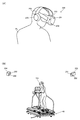
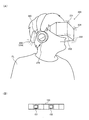
- FIG. 2A and FIG. 2B are examples of the HMD used in this embodiment.
- 3A and 3B are other examples of the HMD used in the present embodiment.
- the structural example of the ski simulator which is an example of a simulation system.
- the structural example of the robot simulator which is an example of a simulation system.
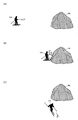
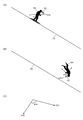
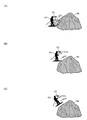
- FIGS. 8A to 8C are explanatory diagrams of problems that occur due to acceleration changes when a character collides with a rock.
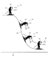
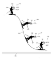
- FIGS. 9A to 9C are explanatory diagrams of problems that occur due to acceleration changes when a character falls from a cliff.
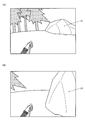
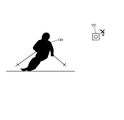
- FIGS. 10B are examples of game images for explaining a scene in which a character collides with a rock.
- FIG. 11A and FIG. 11B are examples of game images for explaining a fade-out process in a scene where a character collides with a rock.
- FIGS. 12A and 12B are examples of game images for explaining a scene where a character falls from a cliff.
- FIG. 13A and FIG. 13B are examples of game images for explaining a fade-out process in a scene where a character falls from a cliff.
- FIG. 14A and FIG. 14B are explanatory diagrams of the effect processing of this embodiment.
- FIG. 15A to FIG. 15C are explanatory diagrams of problems that occur due to a change in the viewing direction of the virtual camera when the character falls.
- FIGS. 15A to FIG. 15C are explanatory diagrams of problems that occur due to a change in the viewing direction of the virtual camera when the character falls.
- FIGS. 15A to FIG. 15C are ex
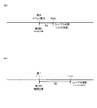
- FIG. 16A and 16B are explanatory diagrams of a method for setting the start timing of fade-out processing and effect processing according to each event.
- FIG. 17A and FIG. 17B are explanatory diagrams of a method for setting a processing start timing and a processing degree according to each event.
- 19A to 19C are explanatory diagrams of a method for changing the position and orientation of the virtual camera based on the tracking information.
- FIGS. 24A to 24C are explanatory diagrams of a virtual camera setting method when falling from a cliff.
- 25 (A) to 25 (C) are explanatory diagrams of a virtual camera setting method at the time of collision with a rock.
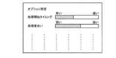
- Explanatory drawing of the method of setting a process start timing and a process degree based on a user's setting information Explanatory drawing of the method of setting a process start timing and a process degree based on a play history.
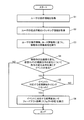
- the flowchart which shows the detailed process example of this embodiment.
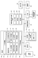
- FIG. 1 is a block diagram showing a configuration example of a simulation system (simulator, game system) of the present embodiment.
- the simulation system of the present embodiment is a system that simulates virtual reality (VR), for example, a game system that provides game content, a real-time simulation system such as a sports competition simulator and a driving simulator, and content that provides content such as video
- VR virtual reality
- the present invention can be applied to various systems such as a system or an operating system for realizing remote work.
- the simulation system of the present embodiment is not limited to the configuration shown in FIG. 1, and various modifications such as omitting some of the components (each unit) or adding other components are possible.
- the movable casing 40 is a casing that changes the play position of the user.
- the movable housing 40 changes the play position of the user in accordance with a change in the traveling direction of the moving body or a course condition on which the moving body moves. Details of the movable housing 40 will be described later.
- the operation unit 160 is for a user (player) to input various operation information (input information).
- the operation unit 160 can be realized by various operation devices such as an operation button, a direction instruction key, a joystick, a handle, a pedal, or a lever.
- the operation unit 160 is realized by the operation members 43 and 44, the footrests 45 and 46, and the like.
- the operation unit 160 is realized by the operation levers 161 and 162, the accelerator pedal 163, the brake pedal 164, and the like.
- the storage unit 170 stores various types of information.
- the storage unit 170 functions as a work area such as the processing unit 100 or the communication unit 196.
- the game program and game data necessary for executing the game program are held in the storage unit 170.
- the function of the storage unit 170 can be realized by a semiconductor memory (DRAM, VRAM), HDD (Hard Disk Drive), SSD, optical disk device, or the like.
- the storage unit 170 includes an object information storage unit 172 and a drawing buffer 178.
- the information storage medium 180 (a computer-readable medium) stores programs, data, and the like, and its function can be realized by an optical disk (DVD, BD, CD), HDD, semiconductor memory (ROM), or the like.
- the processing unit 100 performs various processes of the present embodiment based on a program (data) stored in the information storage medium 180. That is, in the information storage medium 180, a program for causing a computer (an apparatus including an input device, a processing unit, a storage unit, and an output unit) to function as each unit of the present embodiment (a program for causing the computer to execute processing of each unit). Is memorized.
- the HMD 200 (head-mounted display device) is a device that is mounted on the user's head and displays an image in front of the user's eyes.
- the HMD 200 is preferably a non-transmissive type, but may be a transmissive type.
- the HMD 200 may be a so-called glasses-type HMD.
- the HMD 200 includes a sensor unit 210, a display unit 220, and a processing unit 240. A modification in which a light emitting element is provided in the HMD 200 is also possible.
- the sensor unit 210 is for realizing tracking processing such as head tracking, for example.
- the position and direction of the HMD 200 are specified by tracking processing using the sensor unit 210.
- the user's viewpoint position and line-of-sight direction can be specified.
- the first tracking method which is an example of the tracking method
- a plurality of light receiving elements are provided as the sensor unit 210, as will be described in detail with reference to FIGS. 2A and 2B described later.
- the position of the HMD 200 (user's head) in the real world three-dimensional space, Identify the direction.
- a plurality of light emitting elements LEDs are provided in the HMD 200 as will be described in detail with reference to FIGS. 3A and 3B described later.
- a motion sensor is provided as the sensor unit 210, and the position and direction of the HMD 200 are specified using this motion sensor.
- the motion sensor can be realized by, for example, an acceleration sensor or a gyro sensor.
- the position and direction of the HMD 200 in a three-dimensional space in the real world can be specified.
- the position and direction of the HMD 200 may be specified by a combination of the first tracking method and the second tracking method, or a combination of the first tracking method and the third tracking method.
- tracking processing that directly specifies the user's viewpoint position and line-of-sight direction may be employed.
- the display unit 220 of the HMD 200 can be realized by, for example, a liquid crystal display (LCD) or an organic EL display.
- the HMD 200 is provided with a first display arranged in front of the user's left eye and a second display arranged in front of the right eye as the display unit 220.
- stereoscopic display is possible. ing. When performing stereoscopic display, for example, a left-eye image and a right-eye image with different parallaxes are generated, the left-eye image is displayed on the first display, and the right-eye image is displayed on the second display. Note that a left-eye image and a right-eye image may be displayed in the first and second display areas of one display.
- the processing unit 240 of the HMD 200 performs various processes necessary for the HMD 200. For example, the processing unit 240 performs control processing of the sensor unit 210, display control processing of the display unit 220, and the like. Further, the processing unit 240 may perform a three-dimensional sound (stereoscopic sound) process to realize reproduction of a three-dimensional sound direction, distance, and spread.
- a three-dimensional sound stereographic sound
- the sound output unit 192 outputs the sound generated by the present embodiment, and can be realized by, for example, a speaker or headphones.
- the I / F (interface) unit 194 performs interface processing with the portable information storage medium 195, and its function can be realized by an ASIC for I / F processing or the like.
- the portable information storage medium 195 is for a user to save various types of information, and is a storage device that retains storage of such information even when power is not supplied.
- the portable information storage medium 195 can be realized by an IC card (memory card), a USB memory, a magnetic card, or the like.
- the communication unit 196 communicates with the outside (another apparatus) via a wired or wireless network, and functions thereof are hardware such as a communication ASIC or communication processor, or communication firmware. Can be realized.
- a program (data) for causing a computer to function as each unit of this embodiment is distributed from the information storage medium of the server (host device) to the information storage medium 180 (or storage unit 170) via the network and communication unit 196. May be. Use of an information storage medium by such a server (host device) can also be included in the scope of the present invention.
- the processing unit 100 is used for operation information from the operation unit 160, tracking information in the HMD 200 (information on at least one of the position and direction of the HMD, information on at least one of the viewpoint position and the line-of-sight direction), a program, and the like. Based on this, game processing (simulation processing), moving body processing, virtual camera control processing, display processing, or sound processing is performed.
- each process (each function) of this embodiment performed by each unit of the processing unit 100 can be realized by a processor (a processor including hardware).
- each process of the present embodiment can be realized by a processor that operates based on information such as a program and a memory that stores information such as a program.
- the function of each unit may be realized by individual hardware, or the function of each unit may be realized by integrated hardware.
- the processor may include hardware, and the hardware may include at least one of a circuit that processes a digital signal and a circuit that processes an analog signal.
- the processor can be configured by one or a plurality of circuit devices (for example, ICs) mounted on a circuit board or one or a plurality of circuit elements (for example, resistors, capacitors, etc.).
- the processor may be, for example, a CPU (Central Processing Unit). However, the processor is not limited to the CPU, and various processors such as a GPU (GraphicsGProcessing Unit) or a DSP (Digital Signal Processor) can be used.
- the processor may be an ASIC hardware circuit.
- the processor may include an amplifier circuit, a filter circuit, and the like that process an analog signal.
- the memory storage unit 170
- the memory stores instructions that can be read by a computer, and the processing (function) of each unit of the processing unit 100 is realized by executing the instructions by the processor.
- the instruction here may be an instruction set constituting a program, or an instruction for instructing an operation to the hardware circuit of the processor.
- the processing unit 100 includes an input processing unit 102, an arithmetic processing unit 110, and an output processing unit 140.
- the arithmetic processing unit 110 includes a game processing unit 112, a movable housing processing unit 113, a moving body processing unit 114, an object space setting unit 116, a virtual camera control unit 118, a display processing unit 120, and a sound processing unit 130.
- a processor or a processor and a memory
- Various modifications such as omitting some of these components (each unit) or adding other components are possible.
- the input processing unit 102 performs processing for receiving operation information and tracking information, processing for reading information from the storage unit 170, and processing for receiving information via the communication unit 196 as input processing.
- the input processing unit 102 stores, in the storage unit 170, processing for acquiring operation information input by the user using the operation unit 160, tracking information detected by the sensor unit 210 of the HMD 200, and the information specified by the read command.
- a process for reading data from a computer or a process for receiving information from an external device (such as a server) via a network is performed as an input process.
- the reception process includes a process of instructing the communication unit 196 to receive information, a process of acquiring information received by the communication unit 196, and writing the information in the storage unit 170, and the like.
- the arithmetic processing unit 110 performs various arithmetic processes. For example, arithmetic processing such as game processing (simulation processing), moving body processing, virtual camera control processing, display processing, or sound processing is performed.
- arithmetic processing such as game processing (simulation processing), moving body processing, virtual camera control processing, display processing, or sound processing is performed.
- the game processing unit 112 (game processing program module) performs various game processes for the user to play the game.
- the game processing unit 112 (simulation processing unit) executes various simulation processes for the user to experience virtual reality (virtual reality).
- the game process is, for example, a process for starting a game when a game start condition is satisfied, a process for advancing the started game, a process for ending a game when a game end condition is satisfied, or calculating a game result. Processing.
- the movable casing processing unit 113 (movable casing processing program module) performs various processes on the movable casing 40. For example, control processing of the movable housing 40 is performed, and various information detection processing for controlling the movable housing 40 is performed. For example, the movable housing processing unit 113 performs control processing such as air springs 50 to 53 in FIG. For example, a control process for expanding and contracting the air spring portions 50 to 53 is performed. Further, when a swing operation using the operation members 43 and 44 or an edging operation using the footrests 45 and 46 is performed, the movable housing processing unit 113 performs a process for detecting the operation information, and based on the detected operation information. Then, control processing of the movable housing 40 is executed.
- control processing of the movable housing 40 is executed.
- the movable housing processing unit 113 performs control processing of an electric cylinder (not shown) that changes the posture of the base unit 452 in FIG. 6 (pitching, rolling, etc.). For example, the process which controls the linear motion of the rod part of an electric cylinder is performed. Further, the movable casing processing unit 113 performs a process of detecting operation information by the operation levers 161 and 162, the accelerator pedal 163, and the brake pedal 164 of FIG. 6, and controls the movable casing 40 based on the detected operation information. Etc.
- the moving object processing unit 114 (a moving object processing program module) performs various processes on a moving object that moves in the virtual space. For example, a process of moving a moving body or a process of operating the moving body is performed in an object space (game space) that is a virtual space.
- the mobile object processing unit 114 is based on operation information input by the user through the operation unit 160, acquired tracking information, a program (movement / motion algorithm), various data (motion data), and the like. Control processing for moving the model object) in the object space (in the virtual space) or moving the moving body (motion, animation) is performed.
- a simulation for sequentially obtaining movement information (position, rotation angle, speed, or acceleration) and motion information (part object position or rotation angle) of a moving body for each frame for example, 1/60 second.
- a frame is a unit of time for performing a moving / movement process (simulation process) and an image generation process of a moving object.
- the moving body is, for example, a virtual user (virtual player) in a virtual space corresponding to a user (player) in the real space, or a boarding moving body (operation moving body) on which the virtual user is boarded (operated).
- the moving body is a character (virtual user) who skis in a virtual space corresponding to the user in the ski simulator of FIG. 4 described later.
- the object space setting unit 116 (a program module for object space setting processing) performs setting processing of an object space (a virtual space in a broad sense) in which a plurality of objects are arranged.
- object space a virtual space in a broad sense
- various objects representing display objects such as moving objects (people, robots, cars, trains, airplanes, ships, monsters, animals, etc.), maps (terrain), buildings, auditoriums, courses (roads), trees, walls, water surfaces, etc.
- Processing for setting an object an object composed of a primitive surface such as a polygon, a free-form surface, or a subdivision surface) in the object space is performed.
- the position and rotation angle of the object in the world coordinate system are determined, and the rotation angle (rotation angle around the X, Y, and Z axes) is determined at that position (X, Y, Z).
- Arrange objects Specifically, in the object information storage unit 172 of the storage unit 170, object information that is information such as the position of the object (part object) in the object space, the rotation angle, the moving speed, and the moving direction is associated with the object number. Is remembered.
- the object space setting unit 116 performs a process of updating the object information for each frame, for example.
- the virtual camera control unit 118 performs control processing of a virtual camera (viewpoint, reference virtual camera) for generating an image that can be seen from a given (arbitrary) viewpoint of the object space. For example, a process for controlling the position (viewpoint position) or posture (gaze direction) of the virtual camera is performed. Specifically, the process (viewpoint position, line-of-sight direction, or angle of view) that controls the position (X, Y, Z) of the virtual camera and the rotation angle (rotation angle around the X, Y, Z axis) as posture information. Process to control).
- This virtual camera corresponds to the viewpoint of the user (virtual user). In the case of stereoscopic display, a first viewpoint for the left eye (first virtual camera for the left eye) and a second viewpoint for the right eye (second virtual camera for the right eye) are set.
- the display processing unit 120 performs display processing of a game image (simulation image). For example, a drawing process is performed based on the results of various processes (game process, simulation process) performed by the processing unit 100, thereby generating an image and displaying it on the display unit 220 of the HMD 200. Specifically, geometric processing such as coordinate transformation (world coordinate transformation, camera coordinate transformation), clipping processing, perspective transformation, or light source processing is performed. Based on the processing result, drawing data (the position of the vertex of the primitive surface) Coordinates, texture coordinates, color data, normal vector, ⁇ value, etc.) are created.
- the object (one or a plurality of primitive surfaces) after perspective transformation (after geometry processing) is converted into image information in units of pixels such as a drawing buffer 178 (frame buffer, work buffer, etc.).
- an image that can be seen from the virtual camera given viewpoint, left eye and right eye first and second viewpoints
- the drawing processing performed by the display processing unit 120 can be realized by vertex shader processing, pixel shader processing, or the like.
- the sound processing unit 130 performs sound processing based on the results of various processes performed by the processing unit 100. Specifically, game sounds such as music (music, BGM), sound effects, or sounds are generated, and the game sounds are output to the sound output unit 192. Note that part of the sound processing of the sound processing unit 130 (for example, three-dimensional sound processing) may be realized by the processing unit 240 of the HMD 200.
- the output processing unit 140 performs various types of information output processing. For example, the output processing unit 140 performs processing for writing information in the storage unit 170 and processing for transmitting information via the communication unit 196 as output processing. For example, the output processing unit 140 performs a process of writing information specified by a write command in the storage unit 170 or a process of transmitting information to an external apparatus (server or the like) via a network.
- the transmission process is a process of instructing the communication unit 196 to transmit information, or instructing the communication unit 196 to transmit information.
- the simulation system of this embodiment contains the mobile body process part 114, the virtual camera control part 118, and the display process part 120, as shown in FIG.
- An input processing unit 102 can also be included.
- the moving body processing unit 114 performs a process of moving a moving body (virtual user, boarding moving body, etc.) corresponding to the user in the virtual space (object space). For example, processing for obtaining information on the position and direction of the moving body is performed every predetermined period (for example, every frame), and processing for moving the moving body in the course of the virtual space or the like is performed. In addition, the moving body processing unit 114 also performs processing (motion processing) for operating the moving body.
- the virtual camera control unit 118 controls the virtual camera that moves according to the movement of the moving object. For example, a virtual camera that moves so as to follow a moving body is controlled. For example, the virtual camera control unit 118 controls the virtual camera set as the first-person viewpoint of the user. For example, by setting a virtual camera at a position corresponding to the viewpoint of a moving object that moves in the virtual space, and setting the viewpoint position and line-of-sight direction of the virtual camera, the position (positional coordinates) and orientation (rotation axis) of the virtual camera are set. The rotation angle around).
- the display processing unit 120 generates an image that can be viewed from a virtual camera (user viewpoint) in a virtual space as a display image (display video) of the HMD 200. For example, an image that is visible from a given viewpoint is generated in an object space that is a virtual space.
- the generated image is desirably a stereoscopic image.
- the display processing unit 120 determines that the display image of the HMD 200 is an image that can be seen from the virtual camera when it is determined that the change in acceleration of the moving object or the change in the line-of-sight direction of the virtual camera satisfies a given change condition.
- a display process for changing to a different image is performed. For example, when it is determined that a given change condition is satisfied, the display processing unit 120 changes the display image of the HMD 200 to an image different from an image displayed as a normal game image (simulation image). For example, the image is changed to an image different from the game image (simulation image) updated in real time based on the result of the game processing (simulation processing).
- the display image of the HMD 200 is changed to an image in which the burden on the user's eyes (3D sickness or the like) due to a change in acceleration of the moving body or a change in the viewing direction of the virtual camera is reduced.
- Whether or not a given change condition is satisfied may be determined by actually monitoring, for example, a change in acceleration of the moving object or a change in the line-of-sight direction of the virtual camera, or may be such that the given change condition is satisfied. The determination may be made based on whether an event (such as an acceleration change event or a gaze direction change event) has occurred.
- the display processing unit 120 performs display processing for changing the entire display image of the HMD 200 when a given change condition is satisfied. That is, display processing is performed to change the display image as a whole.
- the display processing unit 120 performs display processing that targets all the pixels of the display image. Specifically, display processing is performed in which the pixel values of all the pixels of the display image are changed to given values (for example, pixel values corresponding to a predetermined color such as white or black). Alternatively, effect processing (filter processing) is performed for all pixels of the display image.
- the display processing unit 120 performs a process of fading out the display image as a display process for changing the entire display image. For example, when an event that satisfies a given condition occurs, for example, a process of fading out the display image after a given time has elapsed.
- the fade-out process is a process of gradually bringing the colors of pixels (all pixels) of the display image closer to a predetermined color, for example. Examples of the fade-out process include a white-out process and a black-out process.
- the white-out process is a process for gradually whitening the color (luminance value) of the pixel of the display image.
- the blackout process is a process of gradually blackening the pixel color of the display image. Note that the fade-out process is not limited to the white-out process or the black-out process, and various processes such as a red-out process that gradually turns the colors of all the pixels of the display image red can be assumed.
- the display processing unit 120 may perform display processing for performing a given effect process on an image viewed from the virtual camera when a given change condition is satisfied. For example, when an event that satisfies a given condition occurs, a given effect process is performed on an image viewed from the virtual camera, for example, after a given time has elapsed. In this way, when a given change condition is satisfied, the display image of the HMD 200 can be changed to an image different from the image seen from the virtual camera.
- the effect processing in this case, for example, various processing such as blurring processing, translucent synthesis processing, binarization processing, or mosaic processing can be assumed.
- the effect processing can be realized by performing various types of image filter processing on an image that can be seen from the virtual camera.
- the display processing unit 120 performs an effect process when a given change condition is satisfied by performing an image filter process or the like on an image generated in real time by a game process (simulation process). This effect processing is desirably performed on the entire display image of the HMD 200, but may be performed on a part of the area.
- the display processing unit 120 determines that a given change condition is satisfied when an acceleration change event that changes the traveling direction of the moving body in a direction different from the traveling direction occurs. Then, display processing for changing the display image of the HMD 200 to an image different from the image seen from the virtual camera is performed. For example, an acceleration change event is generated in which it is determined that acceleration (pseudo acceleration in a virtual space) that changes the traveling direction of the moving body to the left, right, down, or up is applied. If so, it is determined that the given change condition is satisfied. For example, when such an acceleration change event occurrence condition is satisfied, it is determined that a given change condition is satisfied. For example, first to Nth acceleration change events are prepared.
- a display process for changing to an image different from the image seen from the virtual camera is performed.
- the display process associated with the mth acceleration change event is performed. Specifically, the display processing is executed at the processing start timing and the processing degree corresponding to the mth acceleration change event.
- the acceleration change event is, for example, at least one of a collision event of the moving object and a falling event of the moving object.
- the acceleration change event may be an event other than a collision event or a fall event.
- the acceleration change event may be a sudden deceleration event, a sudden acceleration event, a steep slope traveling event, or the like.
- a collision event is an event in which a moving object collides with another object in the virtual space, for example. In this way, it is considered that an acceleration (acceleration due to the reaction of the collision) that changes the traveling direction of the moving object has occurred by colliding with another object, so it is determined that a given change condition is satisfied for the acceleration change. . Then, display processing for changing the display image of the HMD 200 to an image different from the image seen from the virtual camera is performed.
- a fall event is an event in which a moving object falls and moves in a downward direction, for example.
- the fall event is an event in which the course (map) does not exist below the moving body and the moving body falls in the downward direction.
- acceleration acceleration due to gravity
- display processing for changing the display image of the HMD 200 to an image different from the image seen from the virtual camera is performed.
- the display processing at the time of occurrence of the collision event and the display processing at the time of occurrence of the falling event may be different. For example, at least one of the processing start timing and the processing degree of the display processing is varied.
- the display processing unit 120 determines that the given change condition is satisfied when the angle change in the viewing direction of the virtual camera is equal to or greater than the given angle, and the display image of the HMD 200 can be seen from the virtual camera. Display processing for changing to an image different from the image is performed. For example, when a situation occurs in which the angle change in the viewing direction of the virtual camera exceeds a given angle, for example, because the moving body falls, rotates, or cannot move. Judge that a given change condition has been met.
- the virtual camera determines that the given change condition is satisfied and A process of changing to an image different from the visible image is executed.
- the display processing unit 120 determines at least one of the processing start timing and the processing degree of the display process for changing to an image different from the image seen from the virtual camera, when the first event that satisfies the given change condition occurs, It differs depending on the occurrence of the second event that satisfies the given change condition. For example, in the first event, the processing start timing of the display process is advanced compared to the second event. In addition, the processing degree of the display process is increased in the first event as compared with the second event.
- the processing start timing is a timing until processing such as fade-out processing and effect processing is started.
- the degree of processing represents, for example, fade-out time in fade-out processing (time required for changing from the original image to a predetermined color), effect strength in effect processing (filter strength), and the like. It is set as a processing parameter for effect processing.
- the first event is, for example, the above-described collision event, and the second event is, for example, a fall event.
- the first event is not limited to this, and various events can be assumed as the first and second events.
- the simulation system of this embodiment includes an input processing unit 102. Then, the input processing unit 102 (input receiving unit) acquires tracking information of the viewpoint information of the user wearing the HMD 200 (head-mounted display device). For example, tracking information (viewpoint tracking information) of viewpoint information that is at least one of the user's viewpoint position and line-of-sight direction is acquired. This tracking information can be acquired by performing tracking processing of the HMD 200, for example. Note that the user's viewpoint position and line-of-sight direction may be directly acquired by tracking processing.
- the virtual camera control unit 118 controls the virtual camera set as the first-person viewpoint of the user. For example, the virtual camera control unit 118 changes the position and orientation of the virtual camera based on tracking information (information on at least one of the user's viewpoint position and line-of-sight direction). For example, the virtual camera control unit 118 sets the virtual camera so that the position (viewpoint position) and posture (gaze direction) of the virtual camera change according to changes in the user's viewpoint position and gaze direction in real space. .
- a virtual camera is set for a virtual user viewpoint (first person viewpoint) in a virtual space.
- a virtual user viewpoint first person viewpoint
- the viewpoint position and line-of-sight direction of the virtual user in the virtual space also changes to that. Will change accordingly. That is, when the user's viewpoint position and line-of-sight direction in the real space change, the position and orientation of the virtual camera in the virtual space change accordingly.
- a virtual user character
- a boarding moving body robot, train, car, motorcycle, bicycle, airplane, ship, etc.
- the position of the virtual camera also changes so as to follow.
- the user can experience a virtual reality in which a virtual user who is his / herself or a boarding mobile body moves in a virtual space.
- the viewpoint of the virtual user in the virtual space is, for example, a first person viewpoint.
- a part of the body of the virtual user (character) is shown in the first person viewpoint image, or the inside of the boarding mobile body is shown. It may be.
- the virtual camera control unit 118 sets the virtual camera so that the change in the posture of at least one of the pitching and rolling of the virtual camera is invalid or restricted even when the moving direction of the moving body changes.
- the posture of the virtual camera is set so as not to perform pitching or rolling without depending on a change in the traveling direction of the moving body. For example, if the user's viewpoint position or line-of-sight direction changes in real space, the position and orientation of the virtual camera change accordingly, but if the moving direction of the moving object changes, the virtual camera changes the moving direction of the moving object Pitching or rolling according to the is not performed.
- the virtual camera is set so that the pitch angle and the roll angle are constant without changing from the initial set angle.
- the virtual camera is set to be parallel to, for example, a horizontal plane (XZ plane) in the world coordinate system of the virtual space.
- the virtual camera is set so as not to change from the vertical direction (Y axis) of the world coordinate system.
- disabling the pitching or rolling posture change means that the pitching or rolling posture change is not performed.
- Limiting the pitching or rolling posture change is to change the pitching or rolling posture at a smaller rotation angle (a sufficiently smaller rotation angle) than the pitching or rolling rotation angle according to the moving direction of the moving body. is there.
- the attitude of the virtual camera can be defined by, for example, a vector of the visual line direction of the virtual camera and an upward vector of the virtual camera (a vector indicating which direction the upward direction of the virtual camera is).
- the gaze direction vector can be set by the gaze position of the virtual camera. For example, by changing the vector of the line-of-sight direction of the virtual camera, it is possible to realize the pitching or yawing posture change (rotational movement) of the virtual camera. For example, by changing the upward vector of the virtual camera, it is possible to change the rolling posture (rotation movement) of the virtual camera.
- the input processing unit 102 acquires tracking information obtained by the tracking process of the HMD 200.
- tracking information for specifying viewpoint information that is at least one of the viewpoint position and the line-of-sight direction of the user is acquired by tracking processing of the HMD 200 as shown in FIGS. 2A to 3B described later.
- This tracking information includes change information of viewpoint information from the initial viewpoint information of the user.
- the tracking information includes the change information of the viewpoint position from the user's initial viewpoint position (change value of the coordinate of the viewpoint position) and the change information of the gaze direction from the user's initial gaze direction (the rotation around the rotation axis in the gaze direction). Change value of the rotation angle). Based on the change information of the viewpoint information included in such tracking information, the user's viewpoint position and line-of-sight direction can be specified.
- the moving body processing unit 114 performs a process of moving the moving body so that at least one posture change of pitching and rolling of the moving body is invalid or restricted even when the traveling direction of the moving body changes.
- the model object of the moving object is arranged and set at the moving position so that the pitching or rolling of the posture of the moving object does not change even when the traveling direction of the moving object moving on the course or the like changes.
- the virtual camera control unit 118 sets the virtual camera at the viewpoint position of the moving object in which the posture change is invalid or restricted.
- the virtual camera is arranged and set at the position of the first-person viewpoint of the moving object corresponding to the virtual user. By doing so, even when the traveling direction of the moving body changes, the posture change of at least one of pitching and rolling of the virtual camera is invalidated or restricted.
- the reference position of the local coordinate system is, for example, the origin position.
- the moving body is arranged and set so that a predetermined position of the moving body (for example, a foot position or a waist position described later) is the origin position of the local coordinate system.
- the local coordinate system is set so that at least one rotational movement of pitching and rolling of the local coordinate system with respect to the world coordinate system is invalid or restricted.
- the viewpoint coordinate system of the virtual camera (the origin of the viewpoint coordinate system) is set at the position of the viewpoint of the moving object in the local coordinate system.
- the method for controlling the attitude of the virtual camera is the above-described method for controlling the attitude of the virtual camera in the technique of moving the moving object so that the pitching or rolling attitude change of the moving object is invalid or restricted even when the moving direction of the moving object changes.
- the method is not limited.
- the image may be projected by a projection device onto a projection screen.
- the projection screen is a screen composed of one curved surface or a plurality of surfaces, for example, a curved screen called a dome-shaped screen.
- the posture of the moving body can be defined by the rotation angle of the moving body (model object) around each of the plurality of rotation axes (X axis, Y axis, Z axis).
- the posture change of the moving body is a rotational movement around each rotation axis.
- the posture of the moving body can be defined by a rotation angle around each rotation axis of the local coordinate system of the moving body with respect to the world coordinate system, and can be represented by, for example, a rotation matrix of coordinate conversion.
- the moving body processing unit 114 is configured so that the change in posture of at least one of the pitching and rolling of the moving body is invalid or restricted even when the traveling direction of the moving body changes due to a change in the course state of the virtual space.
- a process of moving the moving body in the course is performed.
- the posture of a given object accompanying the moving body is changed according to the shape of the course.
- course information corresponding to a course is stored in the storage unit 170, and the moving body processing unit 114 performs moving processing of the moving body based on the course information.
- course information such as course height information and direction information is stored in association with each point on the course, and the moving body processing unit 114 reads the course information of the point corresponding to the position of the moving body to move
- a process of moving the body in the direction of travel is executed.
- the traveling direction of the moving body is set so that it moves in the down direction on the downhill course and moves in the up direction on the uphill course.
- the traveling direction of the moving body is set so that it turns right in the course of the right curve and turns left in the course of the left curve.
- the moving process of the moving body is executed so that the moving body does not change the pitching or rolling posture (so that the posture change is limited). Is done.
- the posture of a given object for example, a ski board or a part of a character body that is a moving body
- the posture of the given object is changed according to the course state (shape, etc.).
- the posture of the given object is changed along the downhill
- the posture of the given object is changed along the uphill.
- the moving body processing unit 114 performs a process of moving the moving body so that the posture of the moving body changes according to the change in the traveling direction of the moving body. For example, if it is a traveling direction that proceeds in the down direction, it changes to a posture that appears to move in the down direction, and if it is a traveling direction that proceeds in the up direction, it appears to be moving in the up direction Change the posture and move the moving body. Similarly, in the case of a traveling direction that turns to the right or left, the moving body is moved by changing the posture to turn right or to appear to turn left.
- the virtual camera control unit 118 also invalidates or restricts the posture change of at least one of pitching and rolling of the virtual camera even when the posture of the moving body changes according to the change in the moving direction of the moving body.
- the pitching posture change of the virtual camera is invalidated or restricted.
- the virtual camera is prevented from changing the pitching posture.
- the change in the posture of rolling of the virtual camera is invalid or limited.
- the virtual camera is prevented from changing the rolling posture.
- a virtual reality simulation process is performed as the game process of the game played by the user.
- the virtual reality simulation process is a simulation process for simulating an event in the real space in the virtual space, and is a process for causing the user to experience the event virtually. For example, a virtual user corresponding to a user in real space or a moving body such as a boarding moving body is moved in the virtual space, or processing for causing the user to experience changes in the environment and surroundings associated with the movement is performed.
- the movable housing 40 changes the play position based on the result of the simulation process that is a game process. For example, the play position is changed based on the result of the moving process of the moving object in the virtual space. For example, a process of changing the play position by the movable housing 40 is performed as a simulation process for causing the user to experience a change in acceleration (acceleration, deceleration) accompanying a change in the user's traveling direction. Alternatively, when the moving body moves on the course, a process of changing the play position by the movable housing 40 is performed as a simulation process for allowing the user to experience the course up and down and unevenness.
- the fluctuation of the display image on the HMD 200 and the change in acceleration experienced by the user are linked to some extent, and the user's 3D sickness can be suppressed. It becomes like this.
- the play position is a play position where the user is positioned when playing a virtual reality (VR) simulation game.
- the play position is a user's ride position in a ride section such as a seat.
- the play position is, for example, a seating position that is a seat ride position.
- the play position is a straddling position.
- the play position is, for example, the user's standing position.
- the simulation system of the present embodiment includes a sound processing unit 130, and the sound processing unit 130 outputs a sound corresponding to a change in the traveling direction of the moving body or an output sound corresponding to the course of the moving body. Generate the process. For example, when the traveling direction of the moving body changes or the course situation changes, an output sound is generated to make the user recognize the change. For example, in a course with unevenness, a sound such as “rattle” is output to make the user audibly recognize that the course has unevenness. In addition, when the user's traveling direction changes abruptly, a sound is output to make the user recognize the acceleration change (acceleration, deceleration, etc.) that changes the traveling direction, and the user hears that the traveling direction has changed. Make them aware. By doing in this way, generation
- the display processing unit 120 changes at least one of the processing start timing and the processing degree of the display processing for changing to an image different from the image seen from the virtual camera based on the setting information by the user or the user's play history information. For example, on the option setting screen for the user to input various setting information of the game, the processing start timing and processing degree of the display processing can be set. Alternatively, the processing start timing and the processing degree of the display processing are changed based on past user play history information. For example, based on play history information, for users who are frequently playing games and are determined to be used to game play, or users who are determined to be advanced players, the processing start timing of the display process is delayed. Or weaken the processing level.
- the processing start timing of the display processing is advanced or the degree of processing is increased.
- a process of changing to an image different from the image seen from the virtual camera is executed in consideration of the number of collisions, the number of drops, the number of falls, or past settings of the user.
- This play history information may be read from the portable information storage medium 195 possessed by the user, or may be downloaded from the server based on identification information such as a user ID stored in the portable information storage medium 195. Good.
- FIG. 2A shows an example of the HMD 200 used in the simulation system of this embodiment.
- the HMD 200 is provided with a plurality of light receiving elements 201, 202, and 203 (photodiodes).
- the light receiving elements 201 and 202 are provided on the front side of the HMD 200, and the light receiving element 203 is provided on the right side of the HMD 200.
- a light receiving element (not shown) is also provided on the left side, upper surface, and the like of the HMD.
- the HMD 200 is provided with a headband 260 and the like so that the user PL can stably wear the HMD 200 on the head with a better wearing feeling.
- the HMD 200 is provided with a headphone terminal (not shown). By connecting a headphone 270 (sound output unit 192) to the headphone terminal, for example, processing of three-dimensional sound (three-dimensional audio) is performed.
- the user PL can listen to the game sound.
- the user's operation information may be input by detecting the user's head whirling motion or head swinging motion by the sensor unit 210 of the HMD 200 or the like.
- base stations 280 and 284 are installed around the simulation system (movable housing 40).
- the base station 280 is provided with light emitting elements 281 and 282, and the base station 284 is provided with light emitting elements 285 and 286.
- the light emitting elements 281, 282, 285, and 286 are realized by LEDs that emit laser (infrared laser or the like), for example.
- the base stations 280 and 284 use these light emitting elements 281, 282, 285, and 286 to emit, for example, a laser beam radially.
- the light receiving elements 201 to 203 and the like provided in the HMD 200 in FIG. 2A receive the lasers from the base stations 280 and 284 so that the tracking of the HMD 200 is realized, and the position and the direction of the head of the user PL are directed. (Viewpoint position, line-of-sight direction) can be detected.
- FIG. 3A shows another example of the HMD 200.
- a plurality of light emitting elements 231 to 236 are provided for the HMD 200. These light emitting elements 231 to 236 are realized by LEDs, for example.
- the light emitting elements 231 to 234 are provided on the front side of the HMD 200, and the light emitting element 235 and the light emitting element 236 (not shown) are provided on the back side. These light emitting elements 231 to 236 emit (emit) light in a visible light band, for example. Specifically, the light emitting elements 231 to 236 emit light of different colors.
- the imaging unit 150 images the light from these light emitting elements 231 to 236. That is, spot images of these light emitting elements 231 to 236 are reflected in the captured image of the imaging unit 150.
- the tracking of the user's PL head (HMD) is implement
- the imaging unit 150 includes first and second cameras 151 and 152, and the first and second cameras 151 and 152 of the first and second cameras 151 and 152 are provided.
- the captured image it is possible to detect the position and the like of the head of the user PL in the depth direction. Further, based on the motion detection information of the motion sensor provided in the HMD 200, the rotation angle (line of sight) of the head of the user PL can also be detected. Therefore, by using such an HMD 200, when the user PL is directed in any direction of all 360 degrees around the user, an image (a user's virtual space) is displayed in the corresponding virtual space (virtual three-dimensional space).
- Image viewed from a virtual camera corresponding to the viewpoint can be displayed on the display unit 220 of the HMD 200.
- the light emitting elements 231 to 236 infrared LEDs instead of visible light may be used.
- the position or movement of the user's head may be detected by another method such as using a depth camera.
- the tracking processing method for detecting the user's viewpoint position and line-of-sight direction is not limited to the method described with reference to FIGS. 2 (A) to 3 (B).
- the tracking process may be realized by a single unit of the HMD 200 using a motion sensor or the like provided in the HMD 200. That is, tracking processing is realized without providing external devices such as the base stations 280 and 284 in FIG. 2B and the imaging unit 150 in FIG. Or you may detect viewpoint information, such as a user's viewpoint position and a gaze direction, by various viewpoint tracking methods, such as well-known eye tracking, face tracking, or head tracking.
- FIG. 4 is a perspective view illustrating a configuration example of a ski simulator which is an example of a simulation system.
- the movable casing 40 has a movable casing 40, and the movable casing 40 includes base portions 41 and 42 facing each other.
- the base portions 41 and 42 are provided to face each other in the DRC direction in FIG.
- air spring parts 50, 51, 52, and 53 are provided at the four corners. These air spring portions 50, 51, 52, and 53 expand and contract in the DRC direction by supplying and discharging air using an air compressor and bubbles.
- the vertical direction is the Y-axis direction
- the direction facing the user PL is the Z-axis direction
- the direction orthogonal to the Y-axis direction and the Z-axis direction is the X-axis direction.
- the base part 41 can be moved upward (upward with respect to the base part 42) in the Y-axis direction by extending all the air spring parts 50, 51, 52, 53.
- all the air spring portions 50, 51, 52, 53 are contracted, the base portion 41 can be moved downward in the Y-axis direction. Due to the movement of the base portion 41 in the vertical direction, for example, the state of the snow surface when skiing can be reproduced. For example, the unevenness of the snow surface can be expressed by moving the base portion 41 in the vertical direction with a small stroke and at a high speed.
- the left air spring portions 50, 51 of the four corner air spring portions 50, 51, 52, 53 contract, and the right air spring portions 52, 53 extend, or the left air spring portions 50, 51 extend, and the right
- the base portion 41 can be rolled around the Z axis.
- the rear air spring portions 50 and 52 are contracted and the front air spring portions 51 and 53 are extended, or the rear air spring portions 50 and 52 are extended and the front air spring portions 51 and 53 are contracted, thereby the base portion. 41 can be pitched around the X axis. By performing such rolling and pitching, it is possible to express the state of a slope that is skiing.
- the movable housing 40 includes operation members 43 and 44.
- the operation members 43 and 44 are provided on the base portion 41.
- the operation member 43 is rotatably provided with a foot platform 45 for placing the left foot of the user PL.
- the operation member 44 is rotatably provided with a footrest 46 for placing the right foot.
- the operation members 43 and 44 swing (sway) in the DRD direction in FIG. That is, the swing movement of yawing around the Y axis becomes possible.
- the footrests 45 and 46 rotate in the DRE direction. That is, rotation around the Z axis is possible.
- the user PL performs an operation using the operation members 43 and 44 and the footrests 45 and 46 in a manner of skiing. For example, by performing a swing operation for swinging the operation members 43 and 44 in the DRD direction and an edging operation for rotating the footrests 45 and 46 in the DRE direction, a ski operation as performed in real-world skiing is performed. Thereby, the user PL can experience the virtual reality in which the virtual user displayed on the HMD 200 performs a corresponding ski operation and skis on the course in the virtual space.
- the movable housing 40 is provided with guide portions 60 and 62.
- the user PL stands at the play position PPL defined by the guide units 60 and 62 and plays a ski simulation game.
- the guide parts 60 and 62 are provided with gripping parts 61 and 63 (the gripping part 63 is not shown) for the user PL to grip by hand.
- the grips 61 and 63 correspond to grips of a real world ski stock.
- the user PL supports his / her body by grasping the grip portions 61 and 63 of the guide portions 60 and 62 simulating such ski stock with his / her hand.
- a swing operation for swinging the operation members 43 and 44 is performed in the manner of skiing, or an edging operation using the footrests 45 and 46 Go and enjoy the ski simulation game.
- wind is sent from the wind tunnel portion 69 provided in front of the user PL, and a virtual reality can be given as if the wind caused by skiing hits the body.
- the guide unit 60 also connects the cable 20 from a processing device that generates a display image of the HMD 200 (a device including the processing unit 100, the storage unit 170, etc. in FIG. 1; for example, a game device, a PC, etc.) from below to above.
- a processing device that generates a display image of the HMD 200
- the guide part 60 is constituted by a pipe having a hollow structure, and the cable 20 from the processing apparatus passes through the pipe of the guide part 60 and is taken out from the cable outlet 65.
- the guide unit 60 includes a rod-shaped support guide 64 that supports the cable 20 at the cable outlet 65 that is the via point TP, and the cable 20 extends from the cable outlet 65 that is the via point TP. It is taken out and connected to the HMD 200.
- the air springs 50 to 53 expand and contract, whereby the base 41 is moved in the vertical direction, the base 41 is rotated about the Z axis, and the pitch is rotated about the X axis.
- the play position PPL of the user PL also changes. That is, when the base part 41 on which the user PL is standing is moved in the vertical direction or is rotated by rolling or pitching, the play position PPL that is the standing position of the user PL is also changed.
- the movable housing 40 determines the play position PPL of the user PL according to the change in the traveling direction of the moving body such as the virtual user in the virtual space or the boarding moving body or the situation of the course in which the moving body moves. Will change.
- FIG. 5 is an example of a game image (simulation image) displayed on the HMD 200 in the ski simulator of FIG.
- This game image is an image from a so-called first person viewpoint.
- an image of a ski course in which a virtual user (virtual skier) corresponding to the user runs and an image of a landscape around the course are displayed realistically.
- These images are displayed to the user by the HMD 200 as so-called stereoscopic images.
- a part of the virtual user's body, skiing and stock are also displayed as appropriate. For example, when the user turns his gaze downward in FIG. 4, a change in the gaze direction is detected by the method described in FIGS.
- skis and stocks are displayed on the game image.
- FIG. 6 is a perspective view showing a configuration example of a robot simulator (robot game device) which is an example of a simulation system.
- a cover portion 451 is provided on a bottom portion 450 (base portion), and a base portion 452 (pedestal portion) is provided thereon.
- the base portion 452 is provided with a seat support portion 464, and the seat portion 462 is mounted on the seat support portion 464, whereby the ride portion 460 is configured.
- a moving part 470 is provided in the base part 452.
- rail portions 454 and 455 are provided on the base portion 452, and a moving portion 470 is provided so as to be movable in a direction along the rail portions 454 and 455.
- the moving part 470 has a support part 472, and an upper surface part 473 (operation base) is provided at the upper end of the support part 472.
- the upper surface portion 473 is provided with operation levers 161 and 162 and a game controller 165 having a sensor portion.
- the sensor unit included in the game controller 165 detects at least one of a position and a direction.
- the operation levers 161 and 162 constitute the operation unit 160 of FIG.
- the game controller 165 is provided with at least one light receiving element used as a sensor unit. And the detection function (at least one detection function of a position and a direction) of the sensor part of the game controller 165 is implement
- the lower surface portion 474 is provided at the lower end of the support portion 472 of the moving portion 470, and the accelerator pedal 163 and the brake pedal 164 are provided on the lower surface portion 474.
- a dash movement is performed in which the robot in the virtual space accelerates and moves.
- the movement of the robot stops.
- a frame portion 430 is provided on the base portion 452 of the movable casing 40.
- a guide portion 432 of the frame portion 430 guides the cable 20 from the processing apparatus. For example, the cable 20 is guided along a predetermined path from the bottom to the top.
- the guided cable 20 is connected to the HMD 200 via the waypoint TP. Specifically, the cable 20 is fixed by the fixing tool 433 at the waypoint TP and connected to the HMD 200.
- Two electric cylinders (not shown) are provided on the back side of the seat 462 of the ride unit 460. As the rod portions of these electric cylinders expand and contract, the posture of the base portion 452 changes. For example, the posture change such as pitching or rolling of the base portion 452 is realized. For example, when the rod portions of two electric cylinders extend together, the pitching posture change of the base portion 452 toward the front side is realized. When the rod portions of the two electric cylinders are contracted together, a change in the pitching posture of the base portion 452 toward the rear side is realized. When one of the rod portions of the two electric cylinders is extended and the other is contracted, the posture change of the rolling of the base portion 452 to the right side or the left side is realized. By changing the pitching and rolling postures of the base portion 452, the user's body can be pitched or rolled.
- FIG. 7 shows an example of a game image displayed on the HMD 200 in the robot simulator of FIG.
- a virtual user corresponding to the user gets on the robot cockpit in the virtual space, and a game image of the robot game in which the opponent battles with the enemy robot or the like is generated.
- the cockpit hood is closed in the virtual world. Then, the user (virtual user) enjoys a game of manipulating the robot in a cockpit in a small space and playing against enemy robots.
- a window WD is provided in the hood FD of the visual-field-type cockpit of the robot in the virtual world, and the user can see the state of the outside world through this window WD. it can.
- a map of the enemy robot ERB, aiming SG, and battle field is displayed in the window WD.
- a missile launcher LAA and a cannon CNB are weapons of robots operated by the user, and bullet number icons SNA and SNB indicating the remaining number of bullets of these weapons.
- the aiming SG moves so as to follow the movement of the line of sight (head, HMD) of the user wearing the HMD 200. For example, if the user turns to the right, the aiming SG on the game image moves to the right, and if the user turns to the left, the aiming SG moves to the left. The user moves the position of the aiming SG to the position of the enemy robot ERB and enjoys the battle game by attacking with the launcher LAA or the cannon CNB.
- the apparatus for realizing the simulation system of the present embodiment is not limited to the apparatuses shown in FIGS.
- the simulation system of the present embodiment has various types such as a home game device, an arcade game device, a personal computer (PC), a portable information terminal, and a large attraction device in which a large number of users participate. Applicable to any device.
- the simulation system of the present embodiment may be realized by a server system in which a plurality of terminal devices (game device, PC, portable information terminal, etc.) are connected via a network. In this case, each process of the present embodiment may be realized by a distributed process between the simulation system and the terminal device.
- the method according to the present embodiment is applied to the ski game of the ski simulator shown in FIG. 4 mainly as an example.
- this embodiment is not limited to this, and various games (RPG, robot battle game, action game, battle game, competition game, sports game, horror experience game, simulation game of vehicles such as trains and airplanes, puzzle game) , Communication games, music games, etc.) and can be applied to other than games.
- RPG robot battle game
- action game battle game
- competition game sports game
- sports game horror experience game
- simulation game of vehicles such as trains and airplanes, puzzle game
- Communication games music games, etc.
- a case where the moving body is a character that is a virtual user will be described as an example.
- the moving body may be a boarding moving body such as a robot, a car, an airplane, or a train on which the virtual user is boarded.
- FIG. 8A a character CH (moving body in a broad sense) that is a skier (virtual user) is sliding on the course in a virtual space.
- a virtual camera is set at the position of the viewpoint of the character CH corresponding to the virtual user in the virtual space, and an image seen from the virtual camera is displayed (stereoscopically displayed) on the HMD 200 as shown in FIG.
- an image from the first person viewpoint can be displayed on the HMD 200, and a virtual reality as if the user is running on a course as a skier in a virtual space can be given to the user.
- FIG. 8A a rock RK (collision target) exists on the front side (traveling direction side) of the character CH.
- FIG. 8B the character CH collides with the rock RK. .
- the traveling direction DT of the character CH changes as shown in FIG.
- the collision event with the rock RK is an acceleration change event that changes the traveling direction DT of the character CH (moving body) in a different direction.
- the traveling direction DT of the character CH is changed from the front direction of the character CH to the right side due to the collision with the rock RK.
- Such a change process of the traveling direction DT can be realized by, for example, performing a collision calculation process (hit check process) between the character CH and the rock RK.
- This collision calculation process can be realized by performing a physical calculation process based on the reaction force that the character CH receives due to the collision with the rock RK.
- physics calculation processing for changing the traveling direction DT of the character CH as shown in FIG. 8C is performed by the reaction force received by the collision shown in FIG.
- FIG. 9 (A) the character CH as a skier is traveling near the cliff CF, and in FIG. 9 (B), it is falling from the cliff CF. Due to the fall from the cliff CF, the traveling direction DT of the character CH is changed as shown in FIG.
- This fall event from the cliff CF is also an acceleration change event that changes the traveling direction DT of the character in a different direction.
- the traveling direction DT of the character CH changes from the front direction of the character CH to the downward direction.
- Such a change process of the traveling direction DT can be realized by performing, for example, a calculation process of the drop movement of the character CH from the cliff CF.
- the calculation process of the fall movement can be realized by performing a physical calculation process based on gravity received by the character CH falling from the cliff CF. For example, physical calculation processing is performed to change the traveling direction DT of the character CH as shown in FIG.
- 3D sickness refers to causing symptoms such as dizziness, such as dizziness, by continuing to watch videos with a three-dimensional effect and intense movement.
- the traveling direction DT of the character CH greatly changes as shown in FIG. 8C due to a collision with the rock RK in FIG. 8B
- the line-of-sight direction of the virtual camera following the character CH also changes greatly.
- the virtual camera is set at the position of the viewpoint of the character CH, and the visual line direction of the virtual camera is directed toward the traveling direction DT of the character CH, for example. Therefore, when the traveling direction DT changes greatly as shown in FIG. 8C, the viewing direction of the virtual camera also changes greatly, and the display image of the HMD in FIG. 5 also changes greatly.
- Such a drastic change in the display image of the HMD when a collision event occurs is due to a pseudo-event (pseudo-collision) in the virtual space, so there is a divergence from the real-world event.
- a drastic change in the display image of the HMD that deviates from the real world occurs, a 3D sickness of the user is caused.
- the movable housing 40 of FIG. 4 is operated so that the reaction force caused by the collision is experienced by the user, thereby reducing the difference between the real world and the virtual world.
- the air springs 50 to 53 are slightly expanded and contracted at the time of a collision with a rock, the vibration caused by the collision can be experienced to some extent by the user.
- a process of changing the display image of the HMD to an image different from the image seen from the virtual camera I do.
- the display image of the HMD is changed to an image different from the image seen from the virtual camera.
- display processing for changing the entire display image of the HMD is performed. Examples of such display processing include processing for fading out a display image and processing for effect processing on an image seen from a virtual camera.
- FIG. 10 (A) is an example of an image displayed on the HMD when the character CH is traveling in the direction of the rock RK as shown in FIG. 8 (A).
- G1 in FIG. 10A there is a rock in the front direction (traveling direction side) of the character CH.
- FIG. 10B is an image at the moment when it collides with the rock of G2, and is an image corresponding to the situation of FIG. 8B.
- the collision direction DT of the character CH greatly changes as shown in FIG. 8C due to the collision with the rock as described above, the display image of the HMD changes drastically, causing problems such as 3D sickness of the user.
- FIG. 11 (A) and FIG. 11 (B) Perform fade-out processing as shown.
- the fade-out process of the display image is started as shown in FIG. 11A, and finally the entire screen is white-out as shown in FIG.
- the rock image shown in G3 has a color closer to white than the rock images in FIGS. 10A and 10B.
- FIGS. 9 (A) and 9 (B) are examples of images displayed on the HMD when the character CH falls over the cliff CF as shown in FIGS. 9 (A) and 9 (B). That is, in FIG. 12A, the character CH is traveling toward the cliff indicated by H1, and in FIG. 12B, the character CH is falling toward the cliff indicated by H2. If the character CH travel direction DT greatly changes as shown in FIG. 9C after falling from the cliff in this way, the HMD display image changes drastically, causing problems such as user 3D sickness.
- fade-out processing as shown in FIGS. 13A and 13B is performed.
- the fade-out process of the display image is started as shown in FIG. 13A, and finally the entire screen is whited out as shown in FIG. 13B.
- FIGS. 9B and 9C after a character CH collides from the cliff CF, a normal game image (simulation) as shown in FIG. Image) is displayed on the HMD. Then, when the given period elapses and the start timing of the fade-out process is reached, the fade-out process (white-out process) as shown in FIGS. 13A and 13B is started.
- the display image of the HMD is an image (a normal game image) that can be seen from the virtual camera.
- the image is different from the simulation image).
- fade-out processing is performed to fade out the entire screen when an acceleration change event such as a collision event or a fall event occurs.
- acceleration change events are events that change the traveling direction DT of the character CH in a direction different from the traveling direction.
- effect processing such as blurring processing and translucent synthesis processing may be performed.
- effect processing is performed on the entire display image.
- the degree of blurring (the processing degree of display processing in a broad sense) may be gradually increased from the start timing of the blurring process.
- the translucent synthesis process can be realized by translucently combining a predetermined image with an image seen from a virtual camera.
- the semi-transparency composition ratio (the processing degree of the display process in a broad sense) of the semi-transparent target image may be gradually increased.
- Various processes can be assumed as the effect process. For example, a binarization process or a mosaic process may be used.
- the effect processing can be realized, for example, by performing image filter processing on an image (original image) seen from a virtual camera.
- the image filter process is, for example, a moving average filter process, a Gaussian filter process, or a median filter process.
- effect processing image filter processing
- FIG. 14B effect processing (image filter processing) may be performed only on a partial area of the display image (for example, the main area at the center).
- the display image of the HMD may be changed to an image different from the image seen from the virtual camera. For example, when an event for changing the viewing direction of the virtual camera occurs, fade-out processing and effect processing are performed.
- FIG. 15A a character CH that is a moving body is traveling on the course CS.
- the virtual camera VC is set to the position of the viewpoint of the character CH, thereby generating an image from the first person viewpoint.
- FIG. 15B the character CH falls down, and the visual line direction CVL of the virtual camera VC changes drastically accordingly.
- the fade-out process described in FIGS. 11A, 11B, 13A, and 13B is performed, or FIGS. 14A and 14B are performed.
- the effect processing described in) is performed. That is, processing for changing the entire display image of the HMD is performed. More specifically, as shown in FIG.
- the display image of the HMD is changed to an image different from the image seen from the virtual camera VC. For example, when it is determined that the line-of-sight direction of the virtual camera VC has changed from the CVL by an angle ⁇ th or more to CVL ′ due to a fall or the like, fade-out processing and effect processing are performed on the display image.
- the display image of the HMD is different from the image seen from the virtual camera when the change in the acceleration of the moving object or the change in the viewing direction of the virtual camera satisfies the given change condition.
- the image is changed. Specifically, when an acceleration change event such as a collision event or a fall event occurs, or when a virtual camera gaze direction change event such as a fall event occurs, display processing for changing the entire display image of the HMD is performed. Do. Specifically, a process for fading out the display image is performed, and an effect process (processing process) for the display image is performed.
- the game when an acceleration change event or a line-of-sight direction change event occurs, fade-out processing and effect processing are performed, and the game is temporarily interrupted. Therefore, the time in which the real world and the virtual world are deviated can be shortened, and the burden on the eyes of the user due to the shaking of the display image of the HMD can be reduced. Then, for example, the game is restarted from the place where the event occurs or the surrounding area. For example, the game is restarted from a place where an event such as a collision, a fall, or a fall occurs, for example, from a place where the game is returned to the game start point, and the user can resume the normal game. Therefore, for example, even when a user who is not familiar with the game or a novice user repeatedly collides, falls, falls, etc., the burden on the eyes of the user is sufficiently reduced, which causes 3D sickness. It can be effectively prevented.
- FIGS. 16A and 16B are diagrams for explaining the details of the fade-out process when an event such as a collision or a drop occurs.
- the processing start timing and the processing level of the display process for changing to an image different from the image seen from the virtual camera are set at the time of occurrence of the first event that satisfies the given change condition and the given change condition. It differs depending on the occurrence of the second event to be satisfied.
- a case where the process of changing to an image different from the image seen from the virtual camera is a fade-out process will be described as an example, but the process has an effect as shown in FIGS. 14A and 14B. Processing etc. may be sufficient.
- a physical calculation process of the collision is performed. For example, when the character CH collides with the rock RK as shown in FIG. 8B, from the traveling direction DT of the character CH at the time of the collision and information on the collision surface of the rock RK (shape information; information on the direction of the collision surface). Then, a physical calculation process is performed to determine the traveling direction DT after the collision. Then, for example, as shown in FIG. 8C, a process of moving the character CH in the determined traveling direction DT is performed.
- the fade-out process (effect process) is not started until a given period TA has elapsed.
- a normal game image is displayed. For example, when the traveling direction DT changes due to a collision, an image seen from the virtual camera is displayed on the HMD. Then, after the period TA has elapsed, the fade-out process is started.
- a drop physical calculation process is performed. For example, as shown in FIG. 9B, when the character CH falls from the cliff CF, physical calculation processing is performed to determine the traveling direction of the character CH after the fall based on information on the speed and gravity acceleration of the character CH. Then, as shown in FIG. 9C, a process of dropping the character CH in the determined traveling direction DT is performed.
- the fade-out process (effect process) is not started until a given period TB elapses.
- a normal game image is displayed. For example, when the traveling direction DT changes due to falling, an image that can be seen from the virtual camera is displayed on the HMD. Then, after the period TB has elapsed, the fade-out process is started.
- the normal game image is displayed until the period TA, TB has elapsed, and then fade-out processing is performed, so the unnatural feeling felt by the user is minimized.
- FIGS. 16A and 16B a normal game image is displayed until the periods TA and TB have elapsed, and then fade-out processing is performed. Therefore, the user can appropriately grasp the collision with the rock or the fall from the cliff by looking at the display image of the HMD during the period TA and TB. Therefore, the user can grasp what kind of situation has occurred due to the collision or the fall, and can prevent the user from feeling unnatural.
- the process start timing of the fade-out process (a process of changing to an image different from the image seen from the virtual camera in a broad sense) Different depending on.
- the process start timing of the fade-out process is different between the collision event (first event) and the fall event (second event).
- the processing start timing TMA is earlier. That is, the period TA is short.
- the processing start timing TMB is later than that in FIG. That is, the period TB is longer than the period TA.
- the process start timing TMA is advanced and the fade-out process (effect process) is started immediately.
- the processing start timing TMB is compared with the processing start timing TMA at the time of the collision in FIG. To slow down. By doing so, the user can experience a virtual experience through the display image of the HMD for a long period of time TB, and can improve the effect of the game.
- the degree of processing of the fade-out processing may be varied depending on the event.
- the degree of fade-out processing differs between a collision event (first event) and a fall event (second event).
- first event the processing degree of the fade-out process is increased and, for example, whiteout is performed in a short time.
- the processing degree of the fade-out process is weakened and, for example, whiteout is performed over a longer time than the collision event.
- the information on the processing start timing is information for specifying the time until display processing such as fade-out processing and effect processing starts after an event occurs, for example.
- Information on the degree of processing is, for example, information for specifying the time from the start of the fade-out process until complete fade-out, or information for specifying the strength of the effect in the effect processing (for example, blurring degree, translucency, filter coefficient, etc.) Etc. In this way, it is possible to vary the processing start timing and processing level according to each event that occurred, and fade-out processing and effect processing at the optimal processing start timing and processing level according to each event. Can be executed.
- FIG. 18 is a diagram illustrating a state in which a character CH, which is a skier, slides on a course CS in a virtual space.
- the horizontal plane HS is a horizontal plane (XZ plane) in the world coordinate system of the virtual space.
- the traveling direction DT of the character CH is parallel (substantially parallel; the same applies hereinafter) to the horizontal plane HS.
- the viewing direction CVL of the virtual camera VC is also parallel (substantially parallel) to the horizontal plane HS.
- the viewpoint position CVP of the virtual camera VC is set, for example, to the position of the viewpoint of the character CH (for example, the position of the eyes), thereby realizing a first person viewpoint.
- the character CH is traveling on the downhill course CS, and the traveling direction DT of the character CH is a direction that makes a depression with respect to the horizontal plane HS. Since the character CH is in a standing posture perpendicular to the plane of the course CS on the downhill (substantially perpendicular, hereinafter the same), the line-of-sight direction CVL of the virtual camera VC also forms a depression with respect to the horizontal plane HS. It is in the direction. After that, in A4, the character CH travels on the flat course CS, and thus the traveling direction DT and the line-of-sight direction CVL of the virtual camera VC return to a direction parallel to the horizontal plane HS.
- the traveling direction DT changes as indicated by A1 to A4 due to the traveling of the character CH of the course CS
- the line-of-sight direction CVL of the virtual camera VC also changes accordingly.
- the display image of the HMD in FIG. 5 also changes greatly according to the change in the line-of-sight direction CVL. For example, in A1, A2, and A3 in FIG.
- the display image in the visual line direction CVL parallel to the horizontal plane HS is changed to the display image in the visual line direction CVL that makes a depression angle with respect to the horizontal plane HS.
- the display image is returned to the display direction CVL parallel to the horizontal plane HS. That is, with the change in the traveling direction DT of the character CH, the line-of-sight direction CVL of the virtual camera VC is greatly changed, and the display image of the HMD is greatly shaken. For example, when the course CS has fine irregularities, the display image shakes violently according to the irregularities.
- 3D sickness of the user is caused.
- a real-world skier detects a change in the direction of travel (change in acceleration, change in gravity direction, change in centrifugal force) with a semicircular canal and the like when there is a undulation in the course as shown in FIG. Orient the direction to look farther away. Thereby, the visible image also does not change, and sickness is prevented.
- the HMD display image shakes.
- a user in the real world does not actually travel on a down or up course, but only the display image of the HMD changes according to the down or up slope of the course in the virtual space. Accordingly, a deviation from the user's intention and feeling occurs, which causes 3D sickness.
- the base portion 41 is pitched around the X axis according to the inclination of the course down or up in the virtual space.
- the user can experience the upward slope to some extent.
- the inclination due to the pitching of the base portion 41 in FIG. 4 is, for example, about 10 degrees or less.
- the user's head is forcibly turned downward or upward according to the course shape of the virtual space. Since an image that is pointed to is displayed on the HMD, 3D sickness is caused.
- the visual line direction CVL of the virtual camera VC corresponding to the user's visual line direction is always parallel (substantially parallel) to the horizontal plane HS, for example, unless the user moves his / her head by himself / herself.
- the line-of-sight direction CVL of the virtual camera VC does not change along the inclination of the course CS as shown in FIG.
- the virtual camera VC is controlled so as to be parallel to the horizontal plane HS.
- the line-of-sight direction CVL of the virtual camera VC is not always parallel to the horizontal plane HS.
- the virtual camera VC If the user turns the line-of-sight direction downward or upward with his own intention or sense, the virtual camera VC The line-of-sight direction CVL also turns downward or upward accordingly. By doing so, it is possible to suppress a situation in which the line-of-sight direction changes regardless of the user's intention and sense while allowing the change in the line-of-sight direction based on the user's intention and reaction. Therefore, it is possible to achieve both improvement of the virtual reality of the user and prevention of 3D sickness caused by the shaking of the display image of the HMD.
- tracking information of the user's viewpoint information is acquired, and the position and orientation of the virtual camera VC are changed based on the acquired tracking information.
- the position of the virtual camera VC corresponds to the viewpoint position CVP
- the posture of the virtual camera VC corresponds to the line-of-sight direction CVL.
- FIGS. 19A to 19C when the real-world user PL points the line-of-sight direction VL (head) downward or upward, tracking information (viewpoint tracking) of the viewpoint information of the user PL is concerned. Information) is acquired by the tracking process of the HMD 200, for example. Then, by setting the viewpoint position CVP and the line-of-sight direction CVL of the virtual camera VC based on the acquired tracking information (specific information on the user's viewpoint position and line-of-sight direction), FIGS. 19A to 19C are set. As described above, the position and orientation of the virtual camera VC are changed. For example, as shown in FIG.
- the line-of-sight direction CVL of the virtual camera VC is also directed downward. If the line-of-sight direction VL of the user PL is directed upward as shown in FIG. 19C, the line-of-sight direction CVL of the virtual camera VC is also directed upward. In this way, when the real-world user PL changes the viewpoint position VP and the line-of-sight direction VL, the viewpoint position CVP and the line-of-sight direction CVL of the virtual camera VC also change accordingly. Accordingly, since the virtual camera VC behaves like the actual first person viewpoint of the user PL, the virtual reality can be improved.
- the user prior to the start of the game, the user is instructed to take a standard pose (standard standing posture).
- the initial viewpoint position and the initial line-of-sight direction of the user are detected by the tracking process of the HMD 200 and stored in the storage unit (HMD or storage unit of the simulation system).
- the change information from the stored initial viewpoint position and the initial line-of-sight direction is acquired as tracking information. That is, change information of the user's viewpoint position and line-of-sight direction is acquired as tracking information.
- the change information of the viewpoint position is a change value of the coordinates of the viewpoint position
- the change information of the line-of-sight direction is a change value of a rotation angle (a rotation angle around the rotation axis) representing the line-of-sight direction.
- the coordinates of the initial viewpoint position are (x0, y0, z0)
- the change values of the coordinates of the viewpoint position are ( ⁇ x, ⁇ y, ⁇ z).
- the rotation angle representing the initial line-of-sight direction is ( ⁇ x0, ⁇ y0, ⁇ z0)
- the change value of the rotation angle representing the line-of-sight direction is ( ⁇ x, ⁇ y, ⁇ z).
- (x, y, z) (x0 + ⁇ x, y0 + ⁇ y, z0 + ⁇ z)
- the viewpoint position and line-of-sight direction of the virtual camera are set, and the position and orientation of the virtual camera are changed.
- the setting of the viewpoint position and the line-of-sight direction of the virtual camera is performed with respect to the coordinates of the initial viewpoint position of the virtual camera and the rotation angle representing the initial line-of-sight direction as described above ( ⁇ x, ⁇ y, ⁇ z), ( ⁇ x, ⁇ y , ⁇ z) can be realized.
- the virtual camera is set at the viewpoint position of the character without depending on the height (physique) of the user who rides on the movable casing 40 in FIG. Therefore, for example, it is not necessary to prepare a character with a different model depending on the height of the user, so that the amount of data can be reduced.
- the position and orientation of the virtual camera VC are changed based on the tracking information acquired by the tracking process.
- the viewpoint position and the line-of-sight direction of the virtual camera VC in the virtual space also change accordingly, so that the user's virtual reality can be improved.
- the traveling direction DT of the character CH changes as shown in FIG. 18, at least one posture change of the virtual camera VC is invalid (or limited).
- the virtual camera VC is set so that
- the traveling direction DT of the character CH changes as shown in B1, B2, B3, and B4 by traveling on the downhill course CS.
- the pitching posture change of the virtual camera VC (rotational motion around the rotation axis corresponding to the pitching) is not performed.
- the line-of-sight direction CVL of the virtual camera VC is a direction parallel to the horizontal plane HS. Maintained. That is, in FIG. 18, the line-of-sight direction CVL of the virtual camera VC changes according to the course CS state (tilt, undulation, shape, etc.), and the pitching posture of the virtual camera VC is changed.
- FIG. 20 the traveling direction DT of the character CH changes as shown in B1, B2, B3, and B4 by traveling on the downhill course CS.
- the pitching posture change of the virtual camera VC rotational motion around the rotation axis corresponding to the pitching
- the line-of-sight direction CVL of the virtual camera VC is a direction parallel to the horizontal plane HS. Main
- the visual line direction CVL of the virtual camera VC does not depend on the state of the course CS, and the pitching posture of the virtual camera VC is not changed.
- the line-of-sight direction CVL of the virtual camera VC is not always parallel to the horizontal plane HS.
- the viewing direction CVL of the virtual camera VC also changes accordingly.
- the rolling of the virtual camera VC is performed even when rolling occurs due to a change in the traveling direction such that the character CH turns to the right or left. Posture change is not performed. That is, the virtual camera VC is set so as not to rotate around the rolling rotation axis. By doing so, in the HMD display image of FIG. 5, the direction of the horizon does not change unless the user tilts his / her head to the left and right, and 3D sickness can be suppressed.
- a change in yawing posture of the virtual camera VC is performed.
- the visual line direction CVL of the virtual camera VC is directed to the right
- the visual line direction CVL of the virtual camera VC is directed to the left.
- the yawing posture is changed.
- an axis along the long axis (optical axis) of the virtual camera VC is a ZV axis
- an axis perpendicular to the ZV axis and parallel to a vertical axis of the world coordinate system is a YV axis
- the ZV axis and YV An axis orthogonal to the axis is taken as an XV axis.
- the pitching of the virtual camera VC is, for example, a rotational movement around the XV axis.
- the rolling of the virtual camera VC is, for example, a rotational movement around the ZV axis.
- Yawing is, for example, a rotational motion around the YV axis.
- the virtual camera VC is not pitched, which is a rotational motion around the XV axis.
- the virtual camera VC is set so that the virtual camera VC is not a rolling motion around the ZV axis. Has been.
- the yawing of the virtual camera VC that is a rotational motion around the YV axis is allowed.
- the virtual camera VC is controlled so as to limit (suppress) the posture change. You may go.
- a change in rolling angle which is an angle of the body axis of the character CH with respect to the vertical axis (axis along the long side direction, vertical axis), is defined as ⁇ .
- the pitch angle and roll angle of the virtual camera VC can be obtained even when the pitching or rolling occurs due to the change in the traveling direction DT of the character CH (moving body). Does not change (or changes in pitch angle and roll angle are limited). For this reason, the situation where the display image of the HMD is greatly shaken or shaken vigorously is prevented, and the occurrence of 3D sickness can be suppressed.
- FIGS. 19A to 19C when the user changes the viewpoint position VP or the line-of-sight direction VL by moving the head or the like, the virtual camera VC is changed accordingly. The posture changes.
- a method of setting the visual line direction of the virtual camera so as to be always parallel to the horizontal plane is conceivable.
- the method of this comparative example is suitable for a system that generates a pseudo three-dimensional image of a normal third person viewpoint.
- the method of this comparative example is not suitable for a system using an HMD because the line-of-sight direction of the virtual camera is always in the horizontal direction regardless of the user's intention and reaction.
- the viewpoint position and line-of-sight direction of the virtual camera change (FIGS. 19A to 19C). Therefore, changes in the viewpoint based on the user's intention and reaction are reflected as changes in the viewpoint of the virtual camera, so that the optimal virtual camera control for the system using the HMD can be realized and the virtual reality of the user can be improved.
- Etc. while reflecting the change in viewpoint based on the user's intention and reaction, the influence of the change in the moving direction of the moving object is not reflected in the pitching or rolling posture change of the virtual camera. . Therefore, it is possible to provide a simulation system capable of preventing the occurrence of 3D sickness while improving the virtual reality.
- FIG. 22 is a diagram for explaining a first realization technique for realizing invalid processing (restriction processing) of the virtual camera pitching or rolling posture change.
- the pitching posture of the character CH is changed according to the state (inclination) of the course CS.
- a posture change is performed in which the character CH pitches forward. That is, the posture change of the pitch angle that is the depression angle with respect to the horizontal direction is performed.
- the posture change in which the character CH pitches backward is performed in the uphill course CS. That is, the posture change of the pitch angle which is an elevation angle with respect to the horizontal direction is performed.
- the character CH does not change the pitching posture even when the traveling direction DT of the character CH changes as indicated by C1 to C4.
- the posture of the character CH is set (fixed) so that the body axis of the character CH (axis connecting the head and feet) is, for example, a right angle (substantially right angle) with respect to the horizontal plane HS of the world coordinate system.
- the character CH in the basic posture (upright posture) is arranged with respect to the position LP (reference coordinates) at the foot of the character CH. Even when the traveling direction DT of the character CH changes, the character CH travels on the course CS with the basic posture (upright posture).
- course height information at each point when the character CH is moved, only the height information of the course information is referred to. Then, for example, only the height of the foot position LP that is the reference position is changed without changing the posture of the character CH.
- the course CS is a downhill course
- the character CH travels on the course CS
- only the height of the character CH (foot position LP) changes, and the posture of the character CH does not change.
- the rolling posture change of the character CH is not performed even when a situation in which the posture is rolled as described in FIG. 21 due to the rightward or leftward cornering. That is, even when there is a change in the traveling direction DT due to cornering, the character CH remains in the basic posture (standing posture) as shown in FIG. 22 without changing the rolling posture as shown in FIG. Drive on CS.
- the viewpoint position CVP of the virtual camera VC is set at the position of the viewpoint (viewpoint coordinate system) of the character CH having such a basic posture.
- the line-of-sight direction CVL of the virtual camera VC is directed in a direction parallel to the horizontal plane HS.
- the viewpoint position of the character CH with respect to the foot position LP is a fixed position, and the viewpoint position CVP of the virtual camera VC is set at this fixed position.
- the basic posture of the character CH is an upright posture
- the line-of-sight direction CVL of the virtual camera VC is oriented in a direction orthogonal (substantially orthogonal) to the body axis of the character CH.
- the character CH as a skier has a basic posture slightly inclined forward. Therefore, the angle formed between the body axis of the character CH and the horizontal plane HS is slightly smaller than 90 degrees, and the angle formed between the body axis of the character CH and the line-of-sight direction CVL of the virtual camera VC is slightly larger than 90 degrees. Become.
- FIG. 23 is a diagram for explaining a second method for realizing the invalidation processing (restriction processing) of the virtual camera pitching or rolling posture change.
- processing is performed to move the character CH so that the posture of the character CH changes in accordance with the change in the traveling direction DT of the character CH (moving body). For example, if the course CS is on a downhill, the posture change that the character CH pitches forward is performed, and if it is the course CS on the uphill, a posture change that pitches backward is performed. In addition, when turning to the right or left, a rolling posture change is performed.
- the traveling direction DT is directed downward, and the character CH is also changed in posture to pitch forward.
- the line-of-sight direction CVL of the virtual camera VC is in the horizontal direction and is in a direction different from the traveling direction DT.
- the visual line direction CVL of the virtual camera VC is a constant direction (horizontal direction). ). Accordingly, it is possible to prevent the display image of the HMD from shaking greatly or shaking violently, and to prevent the occurrence of 3D sickness.
- the posture of character CH changes according to advancing direction DT. For example, if the course CS is downhill, the posture is directed downward, and if the course CS is uphill, the posture is directed upward.
- the battle image is an image used for battle.
- the battle image is an image for an opponent user who is an opponent to view a moving body such as the user's character, for example, an image displayed on the HMD (display unit) of the opponent user.
- An ornamental image is an image used for ornamental purposes.
- the ornamental image is an image for viewing (watching) the state of the game in which the moving body of the user moves.
- the ornamental image is an image displayed on the ornamental monitor so that the gallery can watch the game.
- the demonstration image is an image used for demonstration.
- the demonstration image is an image displayed for demonstration before or after the game starts.
- FIGS. 24A to 24C are diagrams for explaining the posture change of the virtual camera VC at the time of a fall event from the cliff CF.
- the traveling direction DT of the character CH is the downward direction from the horizontal direction.
- the line-of-sight direction CVL of the virtual camera VC does not face the lower side, as shown in FIGS. Maintained in the direction. That is, the pitching posture change of the virtual camera VC is disabled.
- FIG. 24B is an example in the case of using the first realization method of FIG. 22, and FIG. 24C is an example in the case of using the second realization method of FIG.
- the pitching posture change of the character CH is invalid.
- the character CH changes the pitching posture, but the pitching posture change is invalid for the virtual camera VC.
- FIGS. 24B and 24C when the real-world user faces downward as shown in FIG. 19B, the line-of-sight direction CVL of the virtual camera VC is also downward. The user can see the state of the cliff.
- 25 (A) to 25 (C) are diagrams for explaining the posture change of the virtual camera VC at the time of a collision event with the rock RK.
- the traveling direction DT of the character CH changes, for example, upward.
- the method described with reference to FIG. 20 is used.
- the line-of-sight direction CVL of the virtual camera VC does not face the upper direction, and is in the horizontal direction. Maintained. That is, the pitching posture change of the virtual camera VC is disabled.
- FIG. 25B is an example in the case of using the first realization technique of FIG. 22, and FIG. 25C is an example in the case of using the second realization technique of FIG.
- the pitching posture change of the character CH is invalid.
- the second realizing method since the second realizing method is used, the character CH changes the pitching posture, but the pitching posture change is invalid for the virtual camera VC.
- 25 (B) and 25 (C) when the real world user faces upward as shown in FIG. 19 (C), the line-of-sight direction CVL of the virtual camera VC also faces upward. become.
- FIGS. 24A to 25C since the posture change such as the pitching of the virtual camera VC becomes invalid, the occurrence of 3D sickness of the user can be suppressed.
- the visual line direction CVL of the virtual camera VC is maintained horizontal, but the viewpoint position CVP of the virtual camera VC moves downward, so that in FIG. Along with this, the display image of the HMD changes greatly.
- the viewpoint position CVP of the virtual camera VC moves upward, so that the display image of the HMD in FIG. Therefore, the generation of 3D sickness of the user cannot be completely prevented only by the method of invalidating the posture change such as the pitching of the virtual camera.
- the movable housing 40 is controlled so that the posture of the user in the real space is pitched forward. .
- the rear air spring portions 50 and 52 are extended, while the front air spring portions 51 and 53 are contracted.
- an output sound for example, wind noise
- the movable housing 40 is controlled so that the posture of the user in the real space pitches backward.
- the rear air springs 50 and 52 are contracted, while the front air springs 51 and 53 are extended.
- an output sound that makes the user feel like going up an uphill course is output.
- the movable casing 40 is controlled so as to swing the user's play position up and down.
- the air springs 50 to 52 are finely expanded and contracted in the vertical direction.
- an output sound representing a rattling road is output.
- the movable casing 40 and the output sound By controlling the movable casing 40 and the output sound in this way, it is possible to make the user feel the change in the traveling direction of the moving body in the virtual space and the course status using the movable casing 40 and the output sound. Become. For example, it is possible to experience a change in the traveling direction or a change in acceleration or the like due to the course situation by a change in play position by the movable housing 40 or an auditory recognition by a change in output sound. Therefore, the user's sensation and auditory state in the real world and the situation of the moving body and the course in the virtual world coincide to some extent, and the occurrence of 3D sickness can be suppressed.
- the process start timing and the processing degree of the fade-out process and the effect process are changed based on the setting information by the user or the user's play history information. You may let them.
- FIG. 27 is an example of an option setting screen on which the user sets various game options.
- the user can set the processing start timing and processing degree of fade-out processing and effect processing.
- a user who is prone to 3D sickness increases the processing start timing or the processing degree.
- the fade-out process and the effect process are started in a short time or the degree of the process becomes strong, so that it is possible to effectively prevent such a user from causing 3D sickness.
- a user who is less prone to 3D sickness can enjoy a game with more realistic settings by delaying the processing start timing or reducing the processing level.
- the processing start timing and processing degree of the fade-out process and the effect process are set based on the user play history information. For example, for a user who is determined to have a high occurrence rate of events such as a collision, a fall, and a fall based on the user's play history information, the processing start timing is advanced or the processing degree is increased. In this way, for users who are not familiar with game play and users who are determined to be beginners, 3D sickness is caused by increasing the processing start timing or the processing degree. Can be effectively prevented. On the other hand, for a user who is determined to be used to game play or a user who is determined to be an advanced player, it is determined that 3D sickness is unlikely to occur, and the processing start timing is delayed or the processing level is weakened.
- the play history information For example, based on the play history information, the user's number of collisions, number of drops, number of falls, or past settings (option setting, etc.) are specified. And based on information, such as a user's collision frequency, the frequency
- the play history information is stored in, for example, the portable information storage medium 195 (IC card or the like) in FIG. 1, and the processing start timing and the degree of processing are determined based on the play history information from the portable information storage medium 195. Set up. Alternatively, user play history information may be downloaded from an external server.
- user operation information is acquired (step S1). For example, the user operation information input using the operation unit 160 of FIG. 1 is acquired. Further, tracking information of the user viewpoint information is acquired (step S2). For example, the tracking information obtained by the tracking process described in FIGS. 2A to 3B is acquired. And the moving process of a moving body based on a user's operation information, course information, etc. is performed (step S3). For example, based on user operation information, a process of moving a moving body such as a character on a course specified by the course information is executed.
- step S4 it is determined whether or not an event that satisfies a given change condition has occurred with respect to a change in the acceleration of the moving object and a change in the viewing direction of the virtual camera (step S4). For example, it is determined whether the above-described collision event, fall event, or fall event has occurred.
- the processing start timing corresponding to the event has come (step S5). This processing start timing can be acquired using, for example, table data as described with reference to FIG.
- fade-out processing effect processing
- step S6 This degree of processing can be acquired using, for example, table data as described with reference to FIG.
- the present invention is not limited to these, and techniques, processes, and configurations equivalent to these are also included in the scope of the present invention.
- the present invention can be applied to various games. Further, the present invention can be applied to various simulation systems such as a business game device, a home game device, or a large attraction system in which a large number of users participate.
Landscapes
- Engineering & Computer Science (AREA)
- Multimedia (AREA)
- Theoretical Computer Science (AREA)
- Physics & Mathematics (AREA)
- General Engineering & Computer Science (AREA)
- Human Computer Interaction (AREA)
- General Physics & Mathematics (AREA)
- Computer Hardware Design (AREA)
- General Health & Medical Sciences (AREA)
- Health & Medical Sciences (AREA)
- Optics & Photonics (AREA)
- Life Sciences & Earth Sciences (AREA)
- Computing Systems (AREA)
- Geometry (AREA)
- Computer Graphics (AREA)
- Biophysics (AREA)
- Cardiology (AREA)
- Heart & Thoracic Surgery (AREA)
- Physical Education & Sports Medicine (AREA)
- Computer Vision & Pattern Recognition (AREA)
- Processing Or Creating Images (AREA)
- User Interface Of Digital Computer (AREA)
Abstract
Ce système de simulation comprend : une unité de traitement de corps mobile qui exécute un processus pour déplacer, dans un espace virtuel, un corps mobile correspondant à un utilisateur portant un HMD; une unité de commande de caméra virtuelle qui effectue la commande d'une caméra virtuelle qui se déplace selon le mouvement d'un corps mobile; et une unité de traitement d'affichage qui génère, en tant qu'image d'affichage du HMD, une image visible à partir de la caméra virtuelle dans l'espace virtuel. L'unité de traitement d'affichage effectue un traitement d'affichage qui modifie l'image d'affichage du HMD en une image qui est différente de l'image visible à partir de la caméra virtuelle si le changement d'accélération du corps mobile ou la variation de la ligne de visée de la caméra virtuelle est estimé satisfaire aux conditions de changement données.
Priority Applications (2)
| Application Number | Priority Date | Filing Date | Title |
|---|---|---|---|
| CN201780043165.9A CN109478341B (zh) | 2016-07-13 | 2017-07-06 | 模拟系统、处理方法及信息存储介质 |
| US16/245,716 US10955909B2 (en) | 2016-07-13 | 2019-01-11 | Simulation system, processing method, and information storage medium |
Applications Claiming Priority (2)
| Application Number | Priority Date | Filing Date | Title |
|---|---|---|---|
| JP2016-138928 | 2016-07-13 | ||
| JP2016138928A JP6719308B2 (ja) | 2016-07-13 | 2016-07-13 | シミュレーションシステム及びプログラム |
Related Child Applications (1)
| Application Number | Title | Priority Date | Filing Date |
|---|---|---|---|
| US16/245,716 Continuation US10955909B2 (en) | 2016-07-13 | 2019-01-11 | Simulation system, processing method, and information storage medium |
Publications (1)
| Publication Number | Publication Date |
|---|---|
| WO2018012394A1 true WO2018012394A1 (fr) | 2018-01-18 |
Family
ID=60952521
Family Applications (1)
| Application Number | Title | Priority Date | Filing Date |
|---|---|---|---|
| PCT/JP2017/024793 Ceased WO2018012394A1 (fr) | 2016-07-13 | 2017-07-06 | Système de simulation, procédé de traitement et support de stockage d'informations |
Country Status (4)
| Country | Link |
|---|---|
| US (1) | US10955909B2 (fr) |
| JP (1) | JP6719308B2 (fr) |
| CN (1) | CN109478341B (fr) |
| WO (1) | WO2018012394A1 (fr) |
Cited By (3)
| Publication number | Priority date | Publication date | Assignee | Title |
|---|---|---|---|---|
| CN111868667A (zh) * | 2018-03-26 | 2020-10-30 | 索尼公司 | 信息处理装置、信息处理方法和程序 |
| CN112802166A (zh) * | 2021-01-18 | 2021-05-14 | 网易(杭州)网络有限公司 | 模拟虚拟植物受风摆动的显示方法、装置、存储介质及设备 |
| WO2026090441A1 (fr) * | 2024-10-24 | 2026-04-30 | Gilman Jonathan | Dispositif d'instruction et de simulation de ski et ses procédés d'utilisation |
Families Citing this family (17)
| Publication number | Priority date | Publication date | Assignee | Title |
|---|---|---|---|---|
| KR102374404B1 (ko) * | 2017-07-25 | 2022-03-15 | 삼성전자주식회사 | 콘텐트를 제공하기 위한 디바이스 및 방법 |
| JP7104539B2 (ja) * | 2018-03-29 | 2022-07-21 | 株式会社バンダイナムコエンターテインメント | シミュレーションシステム及びプログラム |
| JP2020004263A (ja) * | 2018-06-29 | 2020-01-09 | 株式会社コロプラ | 仮想体験をユーザに提供するためのプログラム、コンピュータ及び方法 |
| JP2020042480A (ja) * | 2018-09-10 | 2020-03-19 | ソニー株式会社 | 情報処理装置、情報処理方法及びプログラム |
| DE102019002403A1 (de) * | 2019-04-02 | 2020-10-08 | Daimler Ag | Verfahren und Vorrichtung zur Beeinflussung einer optischen Ausgabe von Bilddaten auf einer Ausgabeeinrichtung in einem Fahrzeug |
| US11699279B1 (en) * | 2019-06-28 | 2023-07-11 | Apple Inc. | Method and device for heading estimation |
| JP6761888B1 (ja) * | 2019-10-25 | 2020-09-30 | 株式会社バーチャルキャスト | 表示制御装置、表示制御方法、および表示システム |
| US11301047B2 (en) * | 2020-04-24 | 2022-04-12 | Sony Interactive Entertainment Inc. | Hybrid wireless streaming solution, switching from 2D to 3D based on an intuitive hand gesture in virtual reality or augmented reality (AR) head-mounted displays (HMD) |
| US11465031B2 (en) * | 2020-09-16 | 2022-10-11 | RevolutioNice, Inc. | Ambulation simulation systems, terrain simulation systems, treadmill systems, and related systems and methods |
| JP7602243B2 (ja) * | 2020-12-02 | 2024-12-18 | 学校法人渡辺学園 | 練習支援装置、練習支援方法及びプログラム |
| US12028507B2 (en) * | 2021-03-11 | 2024-07-02 | Quintar, Inc. | Augmented reality system with remote presentation including 3D graphics extending beyond frame |
| CN112862935B (zh) * | 2021-03-16 | 2023-03-17 | 天津亚克互动科技有限公司 | 游戏角色的运动处理方法及装置、存储介质、计算机设备 |
| US20230102034A1 (en) * | 2021-09-29 | 2023-03-30 | Lawrence Livermore National Security, Llc | Scenario development for an incident exercise |
| US12449896B2 (en) | 2023-03-31 | 2025-10-21 | Intel Corporation | User-to-avatar action mapping and adjustment |
| CN117018577A (zh) * | 2023-08-11 | 2023-11-10 | 哈尔滨数客科技开发有限公司 | 一种基于vr虚拟体验的山地自行车转向模拟装置 |
| JP2025057138A (ja) * | 2023-09-28 | 2025-04-09 | 株式会社バンダイナムコエンターテインメント | コンピュータシステム、プログラムおよび制御方法 |
| CN120821377B (zh) * | 2025-09-12 | 2026-01-13 | 中汽数据(天津)有限公司 | 一种基于虚拟现实的车辆视野可视化的定量分析方法 |
Citations (3)
| Publication number | Priority date | Publication date | Assignee | Title |
|---|---|---|---|---|
| JP2000339490A (ja) * | 1999-05-28 | 2000-12-08 | Mitsubishi Electric Corp | Vr酔い低減方法 |
| JP2003066825A (ja) * | 2001-08-24 | 2003-03-05 | Mitsubishi Heavy Ind Ltd | 擬似体感装置 |
| JP2015064868A (ja) * | 2013-08-29 | 2015-04-09 | キヤノンマーケティングジャパン株式会社 | 情報処理システムとその処理方法及びプログラム |
Family Cites Families (35)
| Publication number | Priority date | Publication date | Assignee | Title |
|---|---|---|---|---|
| US5354202A (en) * | 1990-08-01 | 1994-10-11 | Atari Games Corporation | System and method for driver training with multiple driver competition |
| WO1994024652A1 (fr) * | 1993-04-20 | 1994-10-27 | Kabushiki Kaisha Ace Denken | Systeme simulateur de conduite |
| JP3428151B2 (ja) * | 1994-07-08 | 2003-07-22 | 株式会社セガ | 画像表示装置を用いた遊戯装置 |
| US5921780A (en) * | 1996-06-28 | 1999-07-13 | Myers; Nicole J. | Racecar simulator and driver training system and method |
| TW394702B (en) * | 1996-10-09 | 2000-06-21 | Sega Enterprises Kk | Player, solution and play implementation and play system |
| WO1999024132A1 (fr) * | 1997-11-07 | 1999-05-20 | Sega Enterprises, Ltd. | Machine de jeu |
| US6010403A (en) * | 1997-12-05 | 2000-01-04 | Lbe Technologies, Inc. | System and method for displaying an interactive event |
| JPH11309269A (ja) | 1998-04-27 | 1999-11-09 | Sony Corp | ゲーム装置、シミュレーション装置及びゲーム画像表示方法 |
| JP3046578B2 (ja) * | 1998-06-11 | 2000-05-29 | 株式会社ナムコ | 画像生成装置及び情報記憶媒体 |
| JP4957938B2 (ja) * | 2001-09-19 | 2012-06-20 | 株式会社セガ | ゲームプログラム、ゲーム装置及びネットワークサーバ |
| WO2003088126A1 (fr) * | 2002-04-05 | 2003-10-23 | Konstantin Sizov | Simulateur de route embarque portable |
| US7126607B2 (en) * | 2002-08-20 | 2006-10-24 | Namco Bandai Games, Inc. | Electronic game and method for effecting game features |
| JP3822617B2 (ja) * | 2004-07-16 | 2006-09-20 | 株式会社コナミデジタルエンタテインメント | ゲーム機の衝撃体感装置およびこの装置を備えたゲーム機 |
| US7625287B2 (en) * | 2005-10-05 | 2009-12-01 | Nintendo Co., Ltd. | Driving game steering wheel simulation method and apparatus |
| JP4761528B2 (ja) * | 2005-10-11 | 2011-08-31 | 任天堂株式会社 | ゲームプログラムおよびゲーム装置 |
| US8021270B2 (en) * | 2008-07-03 | 2011-09-20 | D Eredita Michael | Online sporting system |
| JP5227910B2 (ja) * | 2009-07-21 | 2013-07-03 | 株式会社コナミデジタルエンタテインメント | ビデオゲーム装置、ゲーム画像表示方法及びゲーム画像表示プログラム |
| US9418568B2 (en) * | 2009-09-29 | 2016-08-16 | Advanced Training System Llc | System, method and apparatus for driver training system with dynamic mirrors |
| CN101780321B (zh) * | 2009-12-30 | 2012-01-25 | 永春至善体育用品有限公司 | 一种高临场感的运动健身器材虚拟实景的制作方法以及基于该虚拟实景的互动系统和方法 |
| JP5738569B2 (ja) * | 2010-10-15 | 2015-06-24 | 任天堂株式会社 | 画像処理プログラム、装置、システムおよび方法 |
| US9179619B1 (en) * | 2012-03-01 | 2015-11-10 | Pioneer Hi-Bred International, Inc. | Soybean variety XB72D12 |
| KR101845350B1 (ko) * | 2013-03-26 | 2018-05-18 | 세이코 엡슨 가부시키가이샤 | 두부 장착형 표시 장치 및 두부 장착형 표시 장치의 제어 방법 |
| US9978202B2 (en) * | 2014-02-14 | 2018-05-22 | Igt Canada Solutions Ulc | Wagering gaming apparatus for detecting user interaction with game components in a three-dimensional display |
| US9589384B1 (en) * | 2014-11-26 | 2017-03-07 | Amazon Technologies, Inc. | Perspective-enabled linear entertainment content |
| US10013808B2 (en) * | 2015-02-03 | 2018-07-03 | Globus Medical, Inc. | Surgeon head-mounted display apparatuses |
| CN105653020A (zh) * | 2015-07-14 | 2016-06-08 | 朱金彪 | 穿越时空的方法和装置以及使用其的眼镜或头盔 |
| US10139902B2 (en) | 2015-09-16 | 2018-11-27 | Colopl, Inc. | Method and apparatus for changing a field of view without synchronization with movement of a head-mounted display |
| US10133343B2 (en) * | 2015-12-02 | 2018-11-20 | Tactonic Tecnologies, LLC | Foot operated navigation and interaction for virtual reality experiences |
| CN105320820A (zh) * | 2015-12-02 | 2016-02-10 | 上海航空电器有限公司 | 基于沉浸式虚拟现实平台的快速座舱设计系统及方法 |
| US20170228931A1 (en) * | 2016-02-08 | 2017-08-10 | Google Inc. | Limited field of view in virtual reality |
| JP5996814B1 (ja) * | 2016-02-08 | 2016-09-21 | 株式会社コロプラ | 仮想空間の画像をヘッドマウントディスプレイに提供する方法及びプログラム |
| US10338392B2 (en) | 2016-06-13 | 2019-07-02 | Microsoft Technology Licensing, Llc | Identification of augmented reality image display position |
| JP6689694B2 (ja) * | 2016-07-13 | 2020-04-28 | 株式会社バンダイナムコエンターテインメント | シミュレーションシステム及びプログラム |
| JP6714791B2 (ja) * | 2016-07-13 | 2020-07-01 | 株式会社バンダイナムコエンターテインメント | シミュレーションシステム及びプログラム |
| JP6715192B2 (ja) * | 2017-01-06 | 2020-07-01 | 任天堂株式会社 | ゲームシステム、ゲームプログラム、情報処理装置およびゲーム制御方法 |
-
2016
- 2016-07-13 JP JP2016138928A patent/JP6719308B2/ja active Active
-
2017
- 2017-07-06 CN CN201780043165.9A patent/CN109478341B/zh active Active
- 2017-07-06 WO PCT/JP2017/024793 patent/WO2018012394A1/fr not_active Ceased
-
2019
- 2019-01-11 US US16/245,716 patent/US10955909B2/en active Active
Patent Citations (3)
| Publication number | Priority date | Publication date | Assignee | Title |
|---|---|---|---|---|
| JP2000339490A (ja) * | 1999-05-28 | 2000-12-08 | Mitsubishi Electric Corp | Vr酔い低減方法 |
| JP2003066825A (ja) * | 2001-08-24 | 2003-03-05 | Mitsubishi Heavy Ind Ltd | 擬似体感装置 |
| JP2015064868A (ja) * | 2013-08-29 | 2015-04-09 | キヤノンマーケティングジャパン株式会社 | 情報処理システムとその処理方法及びプログラム |
Cited By (7)
| Publication number | Priority date | Publication date | Assignee | Title |
|---|---|---|---|---|
| CN111868667A (zh) * | 2018-03-26 | 2020-10-30 | 索尼公司 | 信息处理装置、信息处理方法和程序 |
| EP3779644A4 (fr) * | 2018-03-26 | 2021-04-28 | Sony Corporation | Dispositif de traitement d'informations, procédé de traitement d'informations et programme |
| US11480787B2 (en) | 2018-03-26 | 2022-10-25 | Sony Corporation | Information processing apparatus and information processing method |
| CN111868667B (zh) * | 2018-03-26 | 2024-08-23 | 索尼公司 | 信息处理装置、信息处理方法和程序 |
| CN112802166A (zh) * | 2021-01-18 | 2021-05-14 | 网易(杭州)网络有限公司 | 模拟虚拟植物受风摆动的显示方法、装置、存储介质及设备 |
| CN112802166B (zh) * | 2021-01-18 | 2023-08-08 | 网易(杭州)网络有限公司 | 模拟虚拟植物受风摆动的显示方法、装置、存储介质及设备 |
| WO2026090441A1 (fr) * | 2024-10-24 | 2026-04-30 | Gilman Jonathan | Dispositif d'instruction et de simulation de ski et ses procédés d'utilisation |
Also Published As
| Publication number | Publication date |
|---|---|
| JP2018010487A (ja) | 2018-01-18 |
| JP6719308B2 (ja) | 2020-07-08 |
| CN109478341B (zh) | 2024-07-23 |
| US20190220088A1 (en) | 2019-07-18 |
| US10955909B2 (en) | 2021-03-23 |
| CN109478341A (zh) | 2019-03-15 |
Similar Documents
| Publication | Publication Date | Title |
|---|---|---|
| JP6719308B2 (ja) | シミュレーションシステム及びプログラム | |
| US10915166B2 (en) | Simulation system, processing method, and information storage medium | |
| CN109478345B (zh) | 模拟系统、处理方法及信息存储介质 | |
| US10639557B2 (en) | Synchronized motion simulation for virtual reality | |
| US11014000B2 (en) | Simulation system, processing method, and information storage medium | |
| US11090554B2 (en) | Simulation system, image processing method, and information storage medium | |
| US11865453B2 (en) | Simulation system, process method, and information storage medium | |
| WO2018124280A1 (fr) | Système de simulation, procédé de traitement d'image, et support de stockage d'informations | |
| JP6910809B2 (ja) | シミュレーションシステム、プログラム及びコントローラ | |
| JP6712423B2 (ja) | シミュレーションシステム | |
| JP6774260B2 (ja) | シミュレーションシステム | |
| JP6849317B2 (ja) | ゲームシステム | |
| JP7104539B2 (ja) | シミュレーションシステム及びプログラム | |
| JP2018126341A (ja) | シミュレーションシステム及びプログラム | |
| JP7072441B2 (ja) | シミュレーションシステム及びプログラム | |
| JP2013202259A (ja) | プログラム、情報記憶媒体、ゲーム装置、およびサーバシステム | |
| JP2020201980A (ja) | シミュレーションシステム及びプログラム |
Legal Events
| Date | Code | Title | Description |
|---|---|---|---|
| 121 | Ep: the epo has been informed by wipo that ep was designated in this application |
Ref document number: 17827522 Country of ref document: EP Kind code of ref document: A1 |
|
| NENP | Non-entry into the national phase |
Ref country code: DE |
|
| 122 | Ep: pct application non-entry in european phase |
Ref document number: 17827522 Country of ref document: EP Kind code of ref document: A1 |