WO2018012476A1 - Boîte destinée à loger un film adhésif sensible à la pression, dispositif comprenant un film adhésif sensible à la pression logé dans celui-ci, et film de prévention des infections - Google Patents
Boîte destinée à loger un film adhésif sensible à la pression, dispositif comprenant un film adhésif sensible à la pression logé dans celui-ci, et film de prévention des infections Download PDFInfo
- Publication number
- WO2018012476A1 WO2018012476A1 PCT/JP2017/025199 JP2017025199W WO2018012476A1 WO 2018012476 A1 WO2018012476 A1 WO 2018012476A1 JP 2017025199 W JP2017025199 W JP 2017025199W WO 2018012476 A1 WO2018012476 A1 WO 2018012476A1
- Authority
- WO
- WIPO (PCT)
- Prior art keywords
- film
- adhesive film
- adhesive
- storage box
- infection prevention
- Prior art date
- Legal status (The legal status is an assumption and is not a legal conclusion. Google has not performed a legal analysis and makes no representation as to the accuracy of the status listed.)
- Ceased
Links
Images









Classifications
-
- B—PERFORMING OPERATIONS; TRANSPORTING
- B65—CONVEYING; PACKING; STORING; HANDLING THIN OR FILAMENTARY MATERIAL
- B65D—CONTAINERS FOR STORAGE OR TRANSPORT OF ARTICLES OR MATERIALS, e.g. BAGS, BARRELS, BOTTLES, BOXES, CANS, CARTONS, CRATES, DRUMS, JARS, TANKS, HOPPERS, FORWARDING CONTAINERS; ACCESSORIES, CLOSURES, OR FITTINGS THEREFOR; PACKAGING ELEMENTS; PACKAGES
- B65D85/00—Containers, packaging elements or packages, specially adapted for particular articles or materials
- B65D85/67—Containers, packaging elements or packages, specially adapted for particular articles or materials for web or tape-like material
- B65D85/671—Containers, packaging elements or packages, specially adapted for particular articles or materials for web or tape-like material wound in flat spiral form
- B65D85/672—Containers, packaging elements or packages, specially adapted for particular articles or materials for web or tape-like material wound in flat spiral form on cores
-
- A—HUMAN NECESSITIES
- A61—MEDICAL OR VETERINARY SCIENCE; HYGIENE
- A61B—DIAGNOSIS; SURGERY; IDENTIFICATION
- A61B46/00—Surgical drapes
- A61B46/10—Surgical drapes specially adapted for instruments, e.g. microscopes
-
- A—HUMAN NECESSITIES
- A61—MEDICAL OR VETERINARY SCIENCE; HYGIENE
- A61F—FILTERS IMPLANTABLE INTO BLOOD VESSELS; PROSTHESES; DEVICES PROVIDING PATENCY TO, OR PREVENTING COLLAPSING OF, TUBULAR STRUCTURES OF THE BODY, e.g. STENTS; ORTHOPAEDIC, NURSING OR CONTRACEPTIVE DEVICES; FOMENTATION; TREATMENT OR PROTECTION OF EYES OR EARS; BANDAGES, DRESSINGS OR ABSORBENT PADS; FIRST-AID KITS
- A61F15/00—Auxiliary appliances for wound dressings; Dispensing containers for dressings or bandages
- A61F15/001—Packages or dispensers for bandages, cotton balls, drapes, dressings, gauze, gowns, sheets, sponges, swabsticks or towels
-
- B—PERFORMING OPERATIONS; TRANSPORTING
- B65—CONVEYING; PACKING; STORING; HANDLING THIN OR FILAMENTARY MATERIAL
- B65D—CONTAINERS FOR STORAGE OR TRANSPORT OF ARTICLES OR MATERIALS, e.g. BAGS, BARRELS, BOTTLES, BOXES, CANS, CARTONS, CRATES, DRUMS, JARS, TANKS, HOPPERS, FORWARDING CONTAINERS; ACCESSORIES, CLOSURES, OR FITTINGS THEREFOR; PACKAGING ELEMENTS; PACKAGES
- B65D83/00—Containers or packages with special means for dispensing contents
- B65D83/08—Containers or packages with special means for dispensing contents for dispensing thin flat articles in succession
- B65D83/0847—Containers or packages with special means for dispensing contents for dispensing thin flat articles in succession through an aperture at the junction of two walls
- B65D83/0852—Containers or packages with special means for dispensing contents for dispensing thin flat articles in succession through an aperture at the junction of two walls with means for assisting dispensing
- B65D83/0882—Containers or packages with special means for dispensing contents for dispensing thin flat articles in succession through an aperture at the junction of two walls with means for assisting dispensing and for cutting interconnected articles
-
- B—PERFORMING OPERATIONS; TRANSPORTING
- B65—CONVEYING; PACKING; STORING; HANDLING THIN OR FILAMENTARY MATERIAL
- B65H—HANDLING THIN OR FILAMENTARY MATERIAL, e.g. SHEETS, WEBS, CABLES
- B65H16/00—Unwinding, paying-out webs
- B65H16/005—Dispensers, i.e. machines for unwinding only parts of web roll
-
- B—PERFORMING OPERATIONS; TRANSPORTING
- B65—CONVEYING; PACKING; STORING; HANDLING THIN OR FILAMENTARY MATERIAL
- B65H—HANDLING THIN OR FILAMENTARY MATERIAL, e.g. SHEETS, WEBS, CABLES
- B65H18/00—Winding webs
- B65H18/28—Wound package of webs
-
- B—PERFORMING OPERATIONS; TRANSPORTING
- B65—CONVEYING; PACKING; STORING; HANDLING THIN OR FILAMENTARY MATERIAL
- B65H—HANDLING THIN OR FILAMENTARY MATERIAL, e.g. SHEETS, WEBS, CABLES
- B65H35/00—Delivering articles from cutting or line-perforating machines; Article or web delivery apparatus incorporating cutting or line-perforating devices, e.g. adhesive tape dispensers
- B65H35/04—Delivering articles from cutting or line-perforating machines; Article or web delivery apparatus incorporating cutting or line-perforating devices, e.g. adhesive tape dispensers from or with transverse cutters or perforators
- B65H35/06—Delivering articles from cutting or line-perforating machines; Article or web delivery apparatus incorporating cutting or line-perforating devices, e.g. adhesive tape dispensers from or with transverse cutters or perforators from or with blade, e.g. shear-blade, cutters or perforators
-
- C—CHEMISTRY; METALLURGY
- C09—DYES; PAINTS; POLISHES; NATURAL RESINS; ADHESIVES; COMPOSITIONS NOT OTHERWISE PROVIDED FOR; APPLICATIONS OF MATERIALS NOT OTHERWISE PROVIDED FOR
- C09J—ADHESIVES; NON-MECHANICAL ASPECTS OF ADHESIVE PROCESSES IN GENERAL; ADHESIVE PROCESSES NOT PROVIDED FOR ELSEWHERE; USE OF MATERIALS AS ADHESIVES
- C09J7/00—Adhesives in the form of films or foils
- C09J7/20—Adhesives in the form of films or foils characterised by their carriers
- C09J7/22—Plastics; Metallised plastics
- C09J7/24—Plastics; Metallised plastics based on macromolecular compounds obtained by reactions involving only carbon-to-carbon unsaturated bonds
- C09J7/245—Vinyl resins, e.g. polyvinyl chloride [PVC]
-
- C—CHEMISTRY; METALLURGY
- C09—DYES; PAINTS; POLISHES; NATURAL RESINS; ADHESIVES; COMPOSITIONS NOT OTHERWISE PROVIDED FOR; APPLICATIONS OF MATERIALS NOT OTHERWISE PROVIDED FOR
- C09J—ADHESIVES; NON-MECHANICAL ASPECTS OF ADHESIVE PROCESSES IN GENERAL; ADHESIVE PROCESSES NOT PROVIDED FOR ELSEWHERE; USE OF MATERIALS AS ADHESIVES
- C09J2301/00—Additional features of adhesives in the form of films or foils
- C09J2301/10—Additional features of adhesives in the form of films or foils characterized by the structural features of the adhesive tape or sheet
- C09J2301/12—Additional features of adhesives in the form of films or foils characterized by the structural features of the adhesive tape or sheet by the arrangement of layers
- C09J2301/122—Additional features of adhesives in the form of films or foils characterized by the structural features of the adhesive tape or sheet by the arrangement of layers the adhesive layer being present only on one side of the carrier, e.g. single-sided adhesive tape
-
- C—CHEMISTRY; METALLURGY
- C09—DYES; PAINTS; POLISHES; NATURAL RESINS; ADHESIVES; COMPOSITIONS NOT OTHERWISE PROVIDED FOR; APPLICATIONS OF MATERIALS NOT OTHERWISE PROVIDED FOR
- C09J—ADHESIVES; NON-MECHANICAL ASPECTS OF ADHESIVE PROCESSES IN GENERAL; ADHESIVE PROCESSES NOT PROVIDED FOR ELSEWHERE; USE OF MATERIALS AS ADHESIVES
- C09J2301/00—Additional features of adhesives in the form of films or foils
- C09J2301/30—Additional features of adhesives in the form of films or foils characterized by the chemical, physicochemical or physical properties of the adhesive or the carrier
- C09J2301/302—Additional features of adhesives in the form of films or foils characterized by the chemical, physicochemical or physical properties of the adhesive or the carrier the adhesive being pressure-sensitive, i.e. tacky at temperatures inferior to 30°C
-
- C—CHEMISTRY; METALLURGY
- C09—DYES; PAINTS; POLISHES; NATURAL RESINS; ADHESIVES; COMPOSITIONS NOT OTHERWISE PROVIDED FOR; APPLICATIONS OF MATERIALS NOT OTHERWISE PROVIDED FOR
- C09J—ADHESIVES; NON-MECHANICAL ASPECTS OF ADHESIVE PROCESSES IN GENERAL; ADHESIVE PROCESSES NOT PROVIDED FOR ELSEWHERE; USE OF MATERIALS AS ADHESIVES
- C09J2301/00—Additional features of adhesives in the form of films or foils
- C09J2301/30—Additional features of adhesives in the form of films or foils characterized by the chemical, physicochemical or physical properties of the adhesive or the carrier
- C09J2301/312—Additional features of adhesives in the form of films or foils characterized by the chemical, physicochemical or physical properties of the adhesive or the carrier parameters being the characterizing feature
-
- C—CHEMISTRY; METALLURGY
- C09—DYES; PAINTS; POLISHES; NATURAL RESINS; ADHESIVES; COMPOSITIONS NOT OTHERWISE PROVIDED FOR; APPLICATIONS OF MATERIALS NOT OTHERWISE PROVIDED FOR
- C09J—ADHESIVES; NON-MECHANICAL ASPECTS OF ADHESIVE PROCESSES IN GENERAL; ADHESIVE PROCESSES NOT PROVIDED FOR ELSEWHERE; USE OF MATERIALS AS ADHESIVES
- C09J2427/00—Presence of halogenated polymer
- C09J2427/006—Presence of halogenated polymer in the substrate
-
- C—CHEMISTRY; METALLURGY
- C09—DYES; PAINTS; POLISHES; NATURAL RESINS; ADHESIVES; COMPOSITIONS NOT OTHERWISE PROVIDED FOR; APPLICATIONS OF MATERIALS NOT OTHERWISE PROVIDED FOR
- C09J—ADHESIVES; NON-MECHANICAL ASPECTS OF ADHESIVE PROCESSES IN GENERAL; ADHESIVE PROCESSES NOT PROVIDED FOR ELSEWHERE; USE OF MATERIALS AS ADHESIVES
- C09J2433/00—Presence of (meth)acrylic polymer
-
- C—CHEMISTRY; METALLURGY
- C09—DYES; PAINTS; POLISHES; NATURAL RESINS; ADHESIVES; COMPOSITIONS NOT OTHERWISE PROVIDED FOR; APPLICATIONS OF MATERIALS NOT OTHERWISE PROVIDED FOR
- C09J—ADHESIVES; NON-MECHANICAL ASPECTS OF ADHESIVE PROCESSES IN GENERAL; ADHESIVE PROCESSES NOT PROVIDED FOR ELSEWHERE; USE OF MATERIALS AS ADHESIVES
- C09J2475/00—Presence of polyurethane
Definitions
- the present application relates to an adhesive film storage box for storing a wound body configured by winding an adhesive film with high adhesiveness such as an infection prevention film, and an adhesive film storage device in which the wound body is stored in an adhesive film storage box About.
- a doctor sometimes enters a patient's information on a personal computer and creates a medical record while examining and treating the patient.
- the keyboard of the personal computer may be touched with the hand touching the patient. If a patient's body fluid or the like adheres to the keyboard, there is a concern about infection between medical staff such as doctors and nurses, which is not preferable.
- a storage container for an adhesive film that can store an adhesive film so that medical personnel can easily use an adhesive film such as the above-described infection prevention film and can cut the adhesive film to a desired length when in use.
- Patent Document 1 there is a wrap film storage box (see Patent Document 1) that stores a wrap film roll wound with a wrap film.
- this wrap film storage box is used for storing a highly adhesive adhesive film as described above.
- the adhesive film may stick to the front plate of the box and cannot be pulled out well.
- the above-mentioned wrap film storage box is used for storing the above-mentioned adhesive film having high adhesiveness
- the wound body with the film wound is exposed inside the box.
- the adhesiveness of the adhesive film decreases, which is not preferable.
- the present application has been made in view of the above points, and an object thereof is to provide an adhesive film storage box and an adhesive film storage device that can store an adhesive film and can be easily pulled out during use. It is another object of the present application to provide an adhesive film storage box and an adhesive film storage device that are excellent in storage and use of an adhesive film and that allow the adhesive film to be pulled out so that dust does not adhere during use.
- the present inventors have found that the above problem can be solved by making the height of the front plate of the adhesive film storage box lower than the rear plate and the side plate, and have completed the present invention. .
- the present inventors have found that the above problem can be solved by providing an extension piece on the side wall of the adhesive film storage box, and have completed the present invention. That is, the aspect of this invention contains the following.
- An adhesive film storage box for storing a wound body in which an adhesive film having an adhesive property is wound, the main body having at least a front plate, a bottom plate, a rear plate, and a side plate, and having an open top surface
- a lid that can open and close the opening on the upper surface of the main body, and the lid is connected to the upper edge of the rear plate of the main body and is opposed to the upper surface of the main body.
- a lid cover piece connected to the front edge of the top plate and facing the front surface of the main body, and a cutting part capable of cutting the adhesive film is provided on the lower edge of the lid cover piece.
- the front plate is lower than the height of the rear plate and the side plate, and has a height of 50% to 90% of the outer diameter of the core tube of the wound body.
- the main body has an extending piece extending into the main body from the upper part of each side wall on both sides in the longitudinal direction of the main body, and the extending piece is a wound body in the main body.
- the pressure-sensitive adhesive film storage box according to any one of (1) to (5), which is configured to be capable of being pressed toward the center of the main body.
- the said extension piece is an adhesive film storage box as described in (6) which can be extended in the core pipe of the wound body in the said main-body part.
- the adhesive film storage box according to (7), wherein the extended piece has a width that is narrower at a distal end than at a proximal end.
- the extension piece includes a first portion connected to an upper end of the side wall and a second portion connected to the first portion, and the first portion is on a distal end side.
- the side wall includes at least a first side plate facing the inside of the main body portion and a second side plate positioned outside the first side plate, and the first side plate is formed of the main body portion. A folded portion that enters the core tube of the wound body, and the folded portion is formed by bending a portion surrounded by a cut line formed in the first side plate, and the folded portion is folded.
- (12) 2% strain elastic modulus in the flow direction (MD direction), 2% strain elastic modulus in the width direction (TD direction) is 190 to 600 MPa, and tensile elongation in the flow direction (MD direction) and width direction (TD direction)
- a wound infection prevention film comprising a core tube and the infection prevention film according to any one of (12) to (18) wound around the core tube.
- the wound body for infection prevention film according to (19), wherein the pulling force for drawing out the infection prevention film from the core tube is 30 to 300 cN / 200 mm width.
- the pressure-sensitive adhesive film can be stored and easily pulled out at the time of use, so that the user can easily use the pressure-sensitive adhesive film.
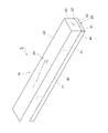
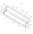
- FIG. 1 It is a perspective view which shows an example of the external appearance of an adhesive film storage apparatus. It is a perspective view which shows an adhesive film storage apparatus when a cover part is open
- FIG. 1 is a perspective view showing an example of an adhesive film storage device 1 according to the present embodiment.
- FIG. 2 is a perspective view of the state in which the adhesive film storage device 1 is opened.
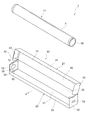
- the adhesive film storage device 1 has an adhesive film storage box 10 and an adhesive film roll 11.
- the “adhesive film” refers to a film having an adhesiveness of 0.01 N / 25 mm or more.
- the entire adhesive film storage box 10 has, for example, a rectangular parallelepiped shape.
- the adhesive film storage box 10 has a main body portion 20 and a lid portion 21 as shown in FIGS. 3 and 4.
- the main body 20 includes, for example, a front plate 30, a bottom plate 31, a rear plate 32, a side plate 33, a front plate side piece 34 as a reinforcing member, a rear plate side piece 35, and the like.
- the lid portion 21 includes, for example, a top plate 40, a lid cover piece 41, a top plate side piece 42, a lid side piece 43, an opening piece 44, and the like.
- the main body 20 is formed in a rectangular parallelepiped shape with an upper surface opened.
- the front plate 30, the bottom plate 31, the rear plate 32, and the side plate 33 are each formed in a square shape and constitute each surface of the main body 20.
- the rear plate side piece 35 is bonded to the inside of the side plate 33 in an overlapping manner.
- a folding portion 50 as a pop-out suppressing member is formed in the center of the rear plate side piece 35.
- the folding part 50 is formed, for example, in a downwardly convex tongue shape (substantially semicircular shape), and a fold line 51 is formed at the upper end.
- the side plate 33 stacked on the outer side of the rear plate side piece 35 is formed with a square push piece 52 for pressing the folded portion 50 of the rear plate side piece 35 from the outer side to fold the folded portion 50 inward.
- the folding part 50 is not folded, and after the adhesive film roll 11 is stored in the main body 20, the pushing piece 52 is pushed from the outside, whereby the folding part 50 is a core described later.
- the adhesive film winding body 11 is held by the folded portion 50 and is folded inside the pipe 60, and as a result, the adhesive film winding body 11 can be prevented from jumping out from the main body portion 20.
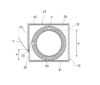
- the rear plate 32 and the side plate 33 are formed at the same height, and the front plate 30 is formed lower than the rear plate 32 and the side plate 33.
- the front plate 30 is formed in a rectangular plate shape having a constant height along the longitudinal direction of the adhesive film storage box 10.
- the front plate 30 is, for example, as high as 50% to 90%, preferably 50% to 80%, more preferably 50% to 67% of the outer diameter R of the core tube 60 of the adhesive film roll 11.
- the height H of the front plate 30 may be less than half the height of the rear plate 32 and the side plate 33.
- the vertical width of the opening on the front surface of the main body 20 caused by the height of the front plate 30 may be more than half of the rear plate 32 and the side plate 33.
- the front plate side piece 34 is overlapped and adhered to the inner side of the rear plate side piece 35.
- the front board 30 has the high intensity
- the top plate 40 of the lid portion 21 extends forward from the upper edge portion of the rear plate 32 and covers the upper surface of the main body portion 20.
- the lid piece 41 extends from the front edge of the top plate 40 to the front surface (front plate 30) side.
- the distal end portion of the lid piece 41 overlaps at least a part of the front plate 30.
- a saw blade-like cutting blade 70 as a cutting portion for cutting the adhesive film F drawn from the adhesive film winding body 11 in the main body portion 20 is provided on the back side of the tip portion of the lid piece 41.
- the material constituting the cutting blade 70 may be resin or paper in addition to metal such as tinplate.
- the adhesive film storage box 10 is sealed by an opening piece 44 connected to the tip of the lid piece 41 of the lid portion 21.
- the opening piece 44 is located on the front surface of the front plate 30 of the main body 20 and is formed in a strip shape along the longitudinal direction of the adhesive film storage box 10.
- the opening piece 44 is connected to the tip of the lid cover piece 41 through a cut line 71 so as to be cut off, and is bonded to a plurality of locations on the surface of the front plate 30.
- the lid 21 can be opened by cutting the opening piece 44 along the longitudinal direction of the box.
- Examples of the base paper constituting the adhesive film storage box 10 include, but are not limited to, cardboard, coated cardboard, cardboard, and the like, and papers known in the industry are appropriately selected and used. Can do.
- the base paper may be one obtained by embossing, printing, or laminating using polyethylene or the like on these materials.
- the adhesive film roll 11 is formed by winding an adhesive film F having adhesive properties such as an infection prevention film around a cylindrical paper core tube 60 (infection prevention film roll).
- Infection prevention film refers to the prevention of adherence of bacteria and viruses, blood and vomiting, and other body fluids in various medical devices that have multiple medical personnel in hospitals, such as electronic medical record keyboards and operation panels. And say a film that prevents cross-infection between medical personnel. Details of the infection prevention film will be described later.
- the pressure-sensitive adhesive film roll 11 in the present embodiment has a longitudinal width of, for example, 100 mm or more, and the diameter of the core tube 60 is about 25 mm to 40 mm.
- the adhesive film F includes an adhesive layer at least in part, and the adhesive strength of the adhesive layer (JIS 0237 compliant 180 degree peeling force) is, for example, 0.01 to 1.5 N / 25 mm.
- the pulling force for pulling out the adhesive film F from the core tube 60 is, for example, 30 to 300 cN / 200 mm width (the pulling force is 30 to 300 cN for the width 200 mm of the adhesive film F).
- an adhesive which comprises an adhesion layer For example, an acrylic adhesive, a rubber adhesive, a silicone adhesive, and a urethane adhesive are mentioned, Among these, an acrylic adhesive, a urethane adhesive Agents are preferred.
- comonomers are added to the main monomer to adjust the cohesive force, or functional group-containing monomers are added to provide crosslinking points to adjust the hardness of the pressure-sensitive adhesive to express the desired pressure-sensitive adhesive force.
- the main monomer is not particularly limited.
- various alkyl (meth) acrylates such as methyl (meth) acrylate, ethyl (meth) acrylate, butyl (meth) acrylate, 2-ethylhexyl (meth) acrylate, and the like. These can be used alone or in combination.
- the comonomer is not particularly limited, and examples thereof include vinyl acetate, acrylonitrile, acrylamide, styrene, methyl methacrylate, and methyl acrylate. Although it does not specifically limit as a functional group containing monomer, For example, acrylic acid, hydroxyethyl acrylate, acrylamide, glycidyl methacrylate, etc. are mentioned. Furthermore, tackiness such as rosin, terpenes, aliphatic and aromatic synthetic resins can be added to adjust the adhesive strength. In addition to the adhesive, a stabilizer, an antioxidant, a light stabilizer, an ultraviolet absorber, and the like may be added.
- polyurethane adhesive will not be restrict
- polyurethane adhesives include other additives such as coupling agents, plasticizers, terpene and rosin tackifiers, inorganic fillers such as calcium carbonate and titanium oxide, antioxidants and ultraviolet absorbers, etc. Stabilizers and the like may be included.
- the polyurethane is not particularly limited as long as it is a polymer having a urethane bond, and examples thereof include a polyurethane having a hydroxyl group.
- Specific examples of the polyurethane having a hydroxyl group include a polymer of an isocyanate compound and a polyol.
- the curing agent examples include aromatic diisocyanates such as diphenylmethane diisocyanate (MDI), tolylene diisocyanate (TDI), and xylene diisocyanate (XDI), and aliphatic diisocyanates such as hexamethylene diisocyanate (HDI). . These may be used alone or in combination of two or more. Among the above curing agents, aliphatic diisocyanates are preferable.
- aromatic diisocyanates such as diphenylmethane diisocyanate (MDI), tolylene diisocyanate (TDI), and xylene diisocyanate (XDI)
- aliphatic diisocyanates such as hexamethylene diisocyanate (HDI).
- the adhesive film includes a base film, and the base film has a 2% strain elastic modulus in the flow direction (MD direction) and a 2% strain elastic modulus in the width direction (TD direction) of 190 to 600 MPa, and a flow.
- the base film may satisfy a tensile elongation of 60 to 200% in the direction (MD direction) and the width direction (TD direction).
- the peeling force between the front plate 30 and the adhesive film F is 0.5 to 5 N / 220 mm, preferably 0.5 to 4 N / 220 mm, and more preferably 0.5 to 3 N / 220 mm.
- the adhesive strength is low and it is difficult to take out the adhesive film F at the next use. If the peel force is higher than 5 N / 220 mm, the adhesive film F is firmly attached to the front plate 30 and it is difficult to pinch the adhesive film F, and partly peels off from the front plate 30 to cause vertical tearing.
- the opening piece 44 is cut out and the pressure-sensitive adhesive film storage box 10 is opened.
- the adhesive film F of the adhesive film roll 11 is pulled out to the front side of the adhesive film storage box 10.
- the adhesive film F is cut into a predetermined length by the cutting blade 70 by, for example, pulling the adhesive film F upward with respect to the adhesive film storage box 10 with the lid portion 21 closed.
- the front plate 30 of the adhesive film storage box 10 is lower than the rear plate 32 and the side plate 33 and is 50% to 90% of the outer diameter R of the core tube 60 of the adhesive film roll 11. Since it has the height H, when pulling out the adhesive film F from the adhesive film storage box 10, it can suppress that the adhesive film F adheres to a front board and becomes difficult to pull out. As a result, according to the adhesive film storage box 10 of the present embodiment, the adhesive film F can be easily pulled out during use while appropriately storing the adhesive film F. In particular, when the adhesive film F is an infection prevention film, the adhesive film F can be stored hygienically, which is preferable.
- the adhesive film F and the core tube 60 form an angle with a small peel force, and the adhesive film F can be pulled out lightly.
- the height H of the front plate 30 exceeds 90% of the diameter of the core tube 60 of the pressure-sensitive adhesive film wound body 11, the case where the pressure-sensitive adhesive to the front plate 30 of the pressure-sensitive adhesive film F cannot be sufficiently suppressed occurs.
- the adhesive film F cannot be pulled out.
- the height H of the front plate 30 is less than 50% of the diameter of the core tube 60 of the pressure-sensitive adhesive film roll 11, the pressure-sensitive adhesive film roll 11 is likely to jump out of the pressure-sensitive adhesive film storage box 10. Further, when the adhesive film is cut, it becomes difficult to cut the adhesive film F between the lid cover piece 41 and the front plate 30, and the cut adhesive film F is rewound so that it is difficult to grasp the end of the adhesive film F at the next use. .
- the folding part 50 is provided in the side surface of the main-body part 20, even if the front board 30 is low, jumping out from the main-body part 20 of the adhesive film winding body 11 can be suppressed.
- the adhesive film winding body 11 may be pulled forward and hit the front plate 30, and an external force may be applied to the front plate 30.
- the height H of the front plate 30 is lower than the side plate 33, the strength of the front plate 30 may be reduced by that amount.
- the adhesive film storage box 10 in the present embodiment is a reinforcing member that reinforces the front plate 30. Therefore, the strength of the front plate 30 against the pressing force of the pressure-sensitive adhesive film roll 11 can be ensured. Therefore, even when the adhesive film F is pulled strongly, the front plate 30 can be prevented from being distorted or damaged.
- a reinforcement member may have another structure.
- a reinforcing plate 90 as a reinforcing member may be provided on the back surface of the front plate 30 as shown in FIGS.
- the reinforcing plate 90 has, for example, an elongated rectangular shape extending from one end to the other end in the longitudinal direction of the front plate 30 and is attached to the inner surface (back surface) of the front plate 30.
- the reinforcing plate 90 has side pieces 91 on the left and right sides, and the side pieces 91 are bonded to the front plate side piece 34, the side plate 33, or the rear plate side piece 35. Further, as shown in FIG. 8, the reinforcing plate 90 may be connected to the front end portion of the front plate 30 and folded inside.
- the reinforcing plate 90 may have other shapes and structures as long as the front plate 30 can be reinforced.
- the pop-up suppressing member that suppresses the sticking out of the main body 20 of the adhesive film wound body 11 may be configured to hold the adhesive film wound body 11 so that the adhesive film wound body 11 does not contact the bottom plate 31.
- the folding portion 100 as the pop-out suppressing member is formed at the center of the rear plate side piece 35.
- the folding part 100 is formed, for example, in a convex tongue shape (substantially semicircular shape) on the rear side, and a folding line 101 is formed on the front side.
- the side plate 33 stacked on the outer side of the rear plate side piece 35 has a substantially semicircular shape for pressing the folding portion 100 of the rear plate side piece 35 from the outer side and folding the folding portion 100 inward as shown in FIGS. 9 and 10.
- a shaped pushing piece 102 is formed.
- the side plate 33 and the rear plate side piece 35 of the main body 20 have, for example, a vertically long rectangular shape, and the folding portion 100 and the pushing piece 102 are formed at a position having a sufficient distance from the bottom plate 31.
- the side plate 33 and the rear plate side piece 35 are formed so that the vertical length I is 1.3 times or more the horizontal width J, for example.
- the folding part 100 is not folded, and after the adhesive film roll 11 is stored in the main body part 20, as shown in FIG.
- the folded part 100 is folded inside the tube of the core tube 60, and the adhesive film wound body 11 is held by the folded part 100 so as not to contact the bottom plate 31.
- the adhesive film roll 11 can be prevented from jumping out from the main body 20.
- the pressure-sensitive adhesive film roll 11 does not contact the bottom plate 31 and can rotate with low friction, the pulling force (force required for pulling out) of the pressure-sensitive adhesive film F is stabilized, and the pulling property is improved.
- the pop-out suppressing member is not limited to the configuration of the folded portion 100 and may have another configuration.
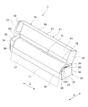
- FIG. 12 is a perspective view illustrating an example of the adhesive film storage device 1 according to the present embodiment.
- FIG. 13 is a perspective view of the state in which the adhesive film storage device 1 is opened.
- the adhesive film storage device 1 has an adhesive film storage box 10 and a wound body 11 of an adhesive film F.
- the entire adhesive film storage box 10 has, for example, a rectangular parallelepiped shape.
- the adhesive film storage box 10 has a main body portion 20 and a lid portion 21 as shown in FIGS. 14 and 15.
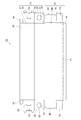
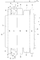
- the main body 20 includes, for example, a front plate 30, a bottom plate 31, a rear plate 32, a front plate side piece 33, a side plate 34 as a first side plate, an extension piece 35, a rear plate side piece 36, and a folded back.
- a back plate 37 and the like are provided.
- the lid portion 21 includes, for example, a top plate 40, a lid cover piece 41, a top plate side piece 42, a lid side piece 43, an opening piece 44, and the like.
- the main body 20 is formed in a rectangular parallelepiped shape whose upper surface is open as shown in FIG.
- the front plate 30, the bottom plate 31, the rear plate 32, and the side plate 34 are each formed in a square shape and constitute the five surfaces of the main body 20.
- the rear plate side piece 36 is connected to both ends of the rear plate 32 in the longitudinal direction (direction A in FIG. 15).
- the front plate side piece 33 is connected to both ends of the front plate 30 in the longitudinal direction.
- the folded back plate 37 is connected to one end of the front plate 30 in the width direction (B direction in FIG. 15).
- the rear plate side piece 36 is folded back to the side plate 34, covers the outer surface of the side plate 34, and is bonded to the outer surface of the side plate 34.
- the front plate side piece 33 is folded back to the side plate 34 side, interposed between the rear plate side piece 36 and the side plate 34, and bonded to the outer surface of the side plate 34.
- the folded back plate 37 is folded on the back surface of the front plate 30 and bonded to the back surface of the front plate 30.
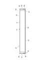
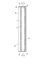
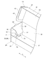
- the extension piece 35 is formed in a substantially rectangular plate shape as shown in FIG. 15, and is connected to the outer ends in the longitudinal direction of the side plates 34 on both sides. As shown in FIGS. 14, 16 to 18, the extending piece 35 is folded into the main body 20 from the upper part of the side plate 34 and extends toward the center of the main body 20.
- the extending piece 35 has a first portion 50 connected to the upper end of the side plate 34 and a second portion 51 connected to the distal end side of the first portion 50.
- the first portion 50 has a base end (connection portion with the side plate 34) having the same width D ⁇ b> 1 as that of the side plate 34, and gradually decreases in width as it approaches the distal end side.
- the second portion 51 has the same width D2 as the distal end of the first portion 50 throughout (from the proximal end to the distal end).
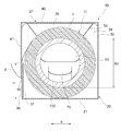
- the width D1 is larger than the inner diameter R1 of the core tube 100 described later of the wound body 11, and the width D2 is smaller than the inner diameter R1.
- the maximum width of the portion of the extending piece 35 located in the core tube 100 is set to 60% to 90% of the inner diameter R1 of the core tube 100.
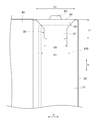
- the length L1 of the extending piece 35 is 10% to 15% of the longitudinal dimension L2 (shown in FIG. 17) in the main body 20, and the height H1 in the main body 20 ( 50% to 80% of (shown in FIG. 19).
- the extending piece 35 extends from the upper end of each side plate 34 to the inside of the core tube 100 of the wound body 11 of the main body 20 as shown in FIGS. Can be pushed to the center side.
- the extension piece 35 is accommodated in the core tube 100 of the wound body 11 by storing the wound body 11 in the main body portion 20 as shown in FIG. Get in.
- a protruding portion 60 that protrudes to the outside of the side plate 34 is formed at the center of the upper end of each side plate 34.
- the protruding portion 60 is formed by forming a cut 61 in the upper portion of the side plate 34 and raising an inner region of the cut 61.
- a dotted cut line 62 is formed at a portion serving as a base end of the protrusion 60 (an upper end of the side plate 34), and the protrusion 60 is bent outward. With this configuration, the protrusion 60 abuts against the inner surface of the lid 21 when the opening of the main body 20 is closed as shown in FIG.
- each side plate 34 a folded portion 70 protruding into the main body 20 is formed.
- the folding part 70 is formed in, for example, a downwardly convex tongue shape (substantially semicircular shape), and a folding line 71 is formed at the upper end.
- the folded portion 70 is folded into the core tube 100 of the wound body 11, and the wound body 11 is held by the folded portion 70, and as a result, the wound body 11 can be prevented from jumping out from the main body portion 20.
- an opening 72 is formed in the side plate 34.
- the opening 72 is closed by a rear plate side piece 36 or a front plate side piece 33 as a second side plate.
- the rear plate 32 and the side plate 34 are formed at the same height, and the front plate 30 is formed lower than the rear plate 32 and the side plate 34.
- the front plate 30 is formed in a rectangular plate shape having a constant height along the longitudinal direction of the adhesive film storage box 10.
- the front plate 30 has a height H of 50% to 90%, preferably 55 to 85%, more preferably 60 to 80% of the outer diameter R2 of the core tube 100 of the wound body 11, for example. have.
- the height H of the front plate 30 may be less than half the height of the rear plate 32 and the side plate 34.
- the vertical width of the opening on the front surface of the main body 20 generated by the low height of the front plate 30 may be half or more of the rear plate 32 and the side plate 34.
- the top plate 40 of the lid portion 21 extends forward from the upper edge portion of the rear plate 32 and covers the upper surface of the main body portion 20.
- the lid piece 41 extends from the front edge of the top plate 40 to the front surface (front plate 30) side.
- the distal end portion of the lid piece 41 overlaps at least a part of the front plate 30.
- a saw blade-like cutting blade as a cutting portion for cutting the adhesive film F drawn from the wound body 11 in the main body portion 20 as shown in FIGS. 90 is provided.
- the material constituting the cutting blade 90 may be resin or paper in addition to metal such as tinplate.
- the adhesive film storage box 10 is sealed by an opening piece 44 connected to the tip of the lid lid piece 41 of the lid portion 21.
- the opening piece 44 is located on the front surface of the front plate 30 of the main body 20 and is formed in a strip shape along the longitudinal direction of the adhesive film storage box 10.
- the opening piece 44 is connected to the tip of the lid cover piece 41 through a cut line 91 so as to be cut off, and is bonded to a plurality of locations on the surface of the front plate 30.
- the lid 21 can be opened by cutting the opening piece 44 along the longitudinal direction of the box as shown in FIG.
- Examples of the base paper constituting the adhesive film storage box 10 include, but are not limited to, cardboard, coated cardboard, cardboard, and the like, and papers known in the industry are appropriately selected and used. Can do.
- the base paper may be one obtained by embossing, printing, or laminating using polyethylene or the like on these materials.
- the wound body 11 is configured by winding an adhesive film F having an adhesive property such as an infection prevention film around a cylindrical paper core tube 100 (an infection prevention film wound body).
- Infection prevention film refers to the prevention of adherence of bacteria and viruses, blood and vomiting, and other body fluids in various medical devices that have multiple medical personnel in hospitals, such as electronic medical record keyboards and operation panels. And say a film that prevents cross-infection between medical personnel. Details of the infection prevention film will be described later.
- the wound body 11 may have the same length in the longitudinal direction A of the core tube 100 and the adhesive film F, and the end surfaces of the core tube 100 and the adhesive film F may be aligned.
- the length of A may be longer than the length of the adhesive film F in the longitudinal direction A, and the end surfaces of the core tube 100 and the adhesive film F may be shifted.
- the former is, for example, a case where the adhesive film F is wound around a sufficiently long core tube 100, and then the core tube 100 is cut to manufacture a wound body 11 having a predetermined length.
- the latter is, for example, a predetermined length.
- the wound body 11 is manufactured by winding the adhesive film F around the core tube 100 cut in advance.
- the wound body 11 wound with the adhesive film F is 90 to 100%, preferably 94 to 100%, more preferably 97 of the core tube 100, where the surface area of the core tube 100 projected from above is 100%.
- the adhesive film F is wound so that a surface area of ⁇ 100% is covered. Thereby, the adhesive film storage box 10 suitable for the width of the adhesive film F can be provided.
- the opening piece 44 is cut out and the adhesive film storage box 10 is opened.
- the adhesive film F of the wound body 11 is pulled out to the front side of the adhesive film storage box 10.
- the adhesive film F is cut into a predetermined length by the cutting blade 90 by, for example, pulling the adhesive film F upward with respect to the adhesive film storage box 10 with the lid 21 closed as shown in FIG.
- the main body 20 has an extending piece 35 extending into the main body 20 from the upper part of the side plate 34, and the extending piece 35 is configured to be able to press the wound body 11 in the main body 20 toward the center side. Therefore, when the adhesive film F is pulled out from the adhesive film storage box 10, the extension piece 35 can press the wound body 11 toward the center, and the movement of the wound body 11 within the main body 20 can be suppressed. Thereby, the end in the longitudinal direction A of the adhesive film F wound around the wound body 11 and the end in the longitudinal direction A of the adhesive film F drawn out from the wound body 11 are on the side of the adhesive film storage box 10.
- the extending piece 35 is configured to be able to extend into the core tube 100 of the wound body 11 in the main body portion 20, it can be brought into contact with the wound body 11 and pressed to the center side. Moreover, since the extending piece 35 enters the core tube 100, the rotating shaft of the wound body 11 is stabilized, so that the adhesive film F can be pulled out smoothly. Further, the extended piece 35 does not hinder the work of replacing the wound body 11, and in the event of trouble such as rewinding of the adhesive film F, the wound body 11 can be easily taken out and repaired, and the adhesive film is stored again. It can be attached to the box 10.
- the extended piece 35 Since the extended piece 35 is narrower at the tip than at the base, it easily enters the core tube 100 of the wound body 11.
- the extension piece 35 has a first portion 50 connected to the upper end of the side plate 34 and a second portion 51 connected to the first portion 50, and the first portion 50 is located on the distal end side. As the distance approaches, the width gradually decreases, and the width of the second portion 51 does not vary. Thereby, since the wound body 11 can be pushed by the 1st part 50 and the wound body 11 can be supported by the 2nd part 51, the wound body 11 can be appropriately pressed to the center side.
- a protrusion 60 that protrudes outward from the side plate 34 is provided on the upper side of each side plate 34, and the protrusion 60 is configured to contact the inner surface of the lid portion 21 that closes the opening of the main body portion 20.
- the projecting portion 60 serves as a fixing member, and the lid portion 21 is firmly fixed to the main body portion 20 in a state where the lid portion 21 is completely closed. Thereby, it can suppress that the cover part 21 opens at the time of use, and dust enters the adhesive film storage box 10, and dust adheres to the adhesive film F.
- the projecting portion 60 Since the dotted cut line 62 is provided at the base end of the projecting portion 60, the projecting portion 60 is reliably bent outward and the lid portion 21 can be appropriately fixed when closed.
- the side plate 34 has a folding portion 70 that enters the core tube 100 of the wound body 11 of the main body portion 20, and the opening of the side plate 34 that is formed by folding the folding portion 70 is the rear plate side piece 36 or the front plate. It is closed by a side piece 33. Thereby, when pulling out the adhesive film F, it can suppress that the wound body 11 jumps out of the main-body part 20, and it can also suppress that dust enters into the adhesive film storage box 10.
- the extending piece 35 extends from the upper end of the side plate 34, but it may extend from another portion constituting the side wall.
- the extending piece 35 may extend from the upper end of the rear plate side piece 36 into the main body 20.
- the extension piece 35 is connected to the outer end of each rear plate side piece 36 on both sides of the rear plate 32 as shown in FIG.
- the overall configuration and shape of the adhesive film storage box 10 are not limited to those of the present embodiment.
- the shape of the extending piece 35 is not limited to that of the above embodiment.
- the extending piece 35 may have the same width from the proximal end to the distal end, or may gradually narrow from the proximal end to the distal end.
- the protruding portion 60 and the folding portion 70 may not be provided.
- the overall configuration and shape of the adhesive film storage box 10 are not limited to those of the present embodiment.
- an infection prevention film can be used as the adhesive film F.
- the infection prevention film has a 2% strain elastic modulus in the flow direction (MD direction) and a 2% strain elastic modulus in the width direction (TD direction) of 190 to 600 MPa, as well as in the flow direction (MD direction) and the width direction (TD direction).
- the substrate film has a tensile elongation of 60 to 200%.
- the infection prevention film of the present embodiment has such a base film, so that, for example, when used as a keyboard cover, the film is not easily stretched even if it is repeatedly touched with a key, so that it is difficult to break and is suitable for infection prevention. .
- the base film used in the present embodiment has a 2% strain elastic modulus in the flow direction (MD direction) of preferably 190 to 550 MPa, more preferably 200 to 500 MPa, and more preferably 200 to 400 MPa. Further preferred. Further, the base film used in the present embodiment has a 2% strain elastic modulus in the width direction (TD direction) of preferably 190 to 550 MPa, more preferably 200 to 500 MPa, and 200 to 400 MPa. More preferably. Furthermore, the base film used in the present embodiment preferably has a tensile elongation in the flow direction (MD direction) of 60 to 180%, more preferably 65 to 170%, and 70 to 165%. More preferably. Furthermore, the base film used in the present embodiment preferably has a tensile elongation in the width direction (TD direction) of 60 to 180%, more preferably 65 to 170%, and 70 to 165%. More preferably it is.
- the infection-preventing film of this embodiment when used as a keyboard cover, tends to be more difficult to break even when repeatedly touched by the key. .
- Various devices include all corners such as office multifunction devices, retail cash registers, backyard weighing machines, hospital MRI and CT inspection equipment switches and operation panels, electronic medical record wagons, stretchers, etc. Equipment.
- the infection prevention film of the present embodiment has a stiffness by setting the density within the range described below, and it becomes easier to handle without causing the films to be entangled with each other.
- the method for controlling the 2% strain elastic modulus and tensile elongation of the base film to the above ranges is not particularly limited.
- a process of extruding a resin and a plasticizer as a single layer or a multi-layer raw material from an annular die examples thereof include a method comprising a step of cooling and solidifying the obtained raw fabric and a step of stretching the cooled and solid raw material.
- the base film is preferably stretched.
- the stretching process is a known process in which stretching is performed in a uniaxial or biaxial direction with respect to the original film.
- the stretching method preferably biaxial stretching, more preferably sequential or simultaneous biaxial stretching method or inflation biaxial stretching method, among which the inflation biaxial stretching method is preferable.
- the 2% strain elastic modulus and tensile elongation of the base film can be measured by the methods described in the examples below.
- the infection prevention film of the present embodiment preferably further includes an adhesive layer.
- the adhesive strength of the adhesive layer (180 degree peel strength in accordance with JIS0237) is preferably 0.01 to 1.5 N / 25 mm, more preferably 0.03 to 1.2 N / 25 mm, and 0 More preferably, it is 0.05 to 1.0 N / 25 mm.
- the infection-preventing film according to the present embodiment further includes such an adhesive layer, so that, for example, when used as a keyboard cover, the infection-preventing film is firmly attached to the keyboard and easily peeled off when removed. Moreover, it becomes easy to handle a film, when a film is affixed by carrying out a fine adhesion process by the said adhesion layer to the base film with the above firm properties.
- the method for controlling the adhesive strength of the adhesive layer within the above range is not particularly limited, and examples thereof include a method of adjusting the hardness of the adhesive and the thickness of the adhesive layer.
- the adhesive strength of the adhesive layer is assumed to be 180 ° peeling force obtained by a measuring method based on JIS0237.
- an acrylic adhesive for example, an acrylic adhesive, a rubber adhesive, a silicone adhesive, a urethane adhesive, for example, an acrylic adhesive, a rubber adhesive
- an adhesive is preferred, and an acrylic pressure-sensitive adhesive is particularly preferred.
- comonomers are added to the main monomer to adjust the cohesive force, or functional group-containing monomers are added to provide crosslinking points to adjust the hardness of the pressure-sensitive adhesive to express the desired pressure-sensitive adhesive force.
- the main monomer is not particularly limited.
- various alkyl (meth) acrylates such as methyl (meth) acrylate, ethyl (meth) acrylate, butyl (meth) acrylate, 2-ethylhexyl (meth) acrylate, and the like. These can be used alone or in combination.
- the comonomer is not particularly limited, and examples thereof include vinyl acetate, acrylonitrile, acrylamide, styrene, methyl methacrylate, and methyl acrylate. Although it does not specifically limit as a functional group containing monomer, For example, acrylic acid, hydroxyethyl acrylate, acrylamide, glycidyl methacrylate, etc. are mentioned. Furthermore, tackiness such as rosin, terpenes, aliphatic and aromatic synthetic resins can be added to adjust the adhesive strength. In addition to the adhesive, a stabilizer, an antioxidant, a light stabilizer, an ultraviolet absorber, and the like may be added.
- the infection-preventing film of this embodiment has an effect that, for example, when used as a keyboard cover, it sticks firmly to the keyboard and easily peels off when peeled off. More expressed. Moreover, it becomes easier to handle without entanglement of the film.
- the thickness of the adhesive layer is preferably 0.5 to 20 ⁇ m, more preferably 1.0 to 17 ⁇ m, and further preferably 3 to 15 ⁇ m, from the viewpoint of the adhesive strength of the adhesive layer.
- the infection prevention film of this embodiment for example, is firmly attached to the keyboard when used as a keyboard cover, and the effect of being easily removed when peeled off is further exhibited. Moreover, it becomes easier to handle without entanglement of the film.
- the layer containing the base film and the adhesive layer preferably has a haze of 0.1 to 25, more preferably 0.1 to 15, More preferably, it is ⁇ 7.
- the infection prevention film of the present embodiment has an effect of having transparency that allows the covered article to be visually recognized.
- the method for controlling the haze of the layer including the base film and the pressure-sensitive adhesive layer to the above range is not particularly limited.
- the components constituting the base film and / or the pressure-sensitive adhesive layer, and the plate during pressure-sensitive adhesive coating And the method of appropriately selecting the smoothness of the release paper and film.
- the haze of the layer including the base film and the adhesive layer can be measured by the method described in the examples below.
- the density of the infection prevention film of the present embodiment is preferably 0.9 to 1.9 g / cm 3 , more preferably 1.2 to 1.9 g / cm 3 , and 1.5 to 1.9 g / cm 3. More preferably, it is 1.8 g / cm 3 .
- the infection prevention film according to the present embodiment has a stiffness, so that the film is more easily handled without being entangled with each other.
- the method for controlling the density of the infection-preventing film of the present embodiment within the above range is not particularly limited, and examples thereof include a method of appropriately selecting the components constituting the base film. Two or more kinds of resins may be combined or a filler may be used.
- the density of a film can be measured by the method as described in the below-mentioned Example.
- the thickness of the substrate film is preferably 5 to 50 ⁇ m, more preferably 10 to 40 ⁇ m, and further preferably 15 to 30 ⁇ m.
- the infection-preventing film of the present embodiment is excellent in durability, and thus is further prevented from being broken, and can be further prevented from infection particularly when used in a medical field.
- the heat shrinkage rate at 120 ° C. of the infection prevention film of the present embodiment is preferably 20 to 45%, more preferably 25 to 40%.
- the infection prevention film of this embodiment is excellent in durability when the heat shrinkage rate at 120 ° C. is in the above range. For example, when used as a keyboard cover, it is difficult to stretch even when repeatedly touched by keys. It can be further suppressed from being caught in the part and hardly broken, and infection can be further prevented particularly when used in a medical field. Moreover, since infection prevention of this embodiment has a firmness when the heat shrinkage rate at 120 ° C. is in the above range, the film is more easily handled without being entangled with each other.
- the thermal shrinkage rate at 120 ° C. of the base film can be measured by the method described in the examples described later.
- the critical surface tension obtained by a Zisman plot at 20 ° C. of the substrate film is preferably 35 to 50 mN / m, and more preferably 38 to 42 mN / m.
- the adhesive is easily applied.
- the critical surface tension at 20 ° C. of the base film can be obtained by a Zisman plot.
- the component constituting the base film is not particularly limited, but examples thereof include polyolefins such as polyvinylidene chloride, polyethylene and polypropylene, polyesters such as polyethylene terephthalate, ethylene / vinyl alcohol copolymer, ethylene / vinyl acetate copolymer.
- a polymer, polyamide, polyurethane, or the like can be used as the material.
- polyvinylidene chloride and electron beam-crosslinked polyethylene are preferable, and polyvinylidene chloride is more preferable.
- Polyvinylidene chloride is a mixture of 1 to 10 of 100 parts by weight of a vinylidene chloride copolymer satisfying a weight average molecular weight of 70,000 to 140,000 and a vinylidene chloride monomer unit of 75 to 96% by mass, a fatty acid ester and an epoxidized compound. It is preferable that it contains a mass part.
- the components constituting the base film may be used alone or in combination of two or more.
- the base film is particularly preferably a vinylidene chloride copolymer as a main component.
- the main component means a component of 70% by mass or more, preferably 75% by mass or more, more preferably 85% by mass or more, and still more preferably 90% when all components are 100% by mass. It is at least 100% by mass, particularly preferably 100% by mass.
- the infection prevention film of this embodiment may further include a release layer on the back surface of the base film.
- a release layer When the infection prevention film of this embodiment contains a release layer, it tends to be easily unwound.
- release layer is not particularly limited, for example, a silicone type or a long chain alkyl pendant polymer type can be used.
- the thickness of the release layer is preferably 0.1 to 1.0 ⁇ m, more preferably 0.15 to 0.9 ⁇ m, and further preferably 0.2 to 0.7 ⁇ m.
- the infection prevention film of this embodiment may be provided with a printing layer or a primer layer.
- the infection prevention film of the present embodiment may further have a separator on the adhesive layer side of the layer including the base film and the adhesive layer.
- a separator is not specifically limited, For example, the polyethylene terephthalate (PET) film, paper, etc. which expressed the release property by the silicone process can be used.
- the manufacturing method of the infection prevention film of this embodiment will not be specifically limited if it is a method which has a base film which 2% strain elastic modulus and tensile elongation satisfy
- the base film satisfying the above-described ranges of the 2% strain elastic modulus and the tensile elongation includes, for example, a step of extruding a resin and a plasticizer from a circular die as a single layer or a multilayer original fabric, and cooling the extruded original fabric.
- stretching the raw material cooled and solidified can be mentioned.
- the stretching process is a known process in which stretching is performed in a uniaxial or biaxial direction with respect to the film original.
- the stretching method preferably biaxial stretching, more preferably sequential or simultaneous biaxial stretching method or inflation biaxial stretching method, among which the inflation biaxial stretching method is preferable.
- the infection prevention film of this embodiment can be obtained, for example, by applying an adhesive to the base film obtained as described above with a comma coater or gravure coater, winding it after drying, and aging at 40 ° C. for 2 days. it can.
- a primer having an affinity for the adhesive layer and the base material layer may be applied in advance, or the base film may be subjected to corona treatment.
- the wound prevention film wound body of this embodiment includes a core tube and the above-described infection prevention film wound around the core tube.
- the infection prevention film roll the adhesive film roll 11 and the roll 11 described in the first and second embodiments can be used.
- the material of the core tube is not limited, and for example, paper, plastic, metal, or the like can be used.
- the core tube may be a hollow cylindrical object or a non-hollow cylindrical object.
- the diameter of the core tube is not limited, and can be, for example, 10 mm to 50 mm.
- the pulling force for drawing out the infection prevention film from the core tube is preferably 30 to 300 cN / 200 mm width, more preferably 35 to 250 cN / 200 mm width, More preferably, the width is 40 to 200 cN / 200 mm.
- the method for controlling the pulling force for pulling out the infection prevention film from the core tube to the above range is not particularly limited.
- a release layer is provided on the back surface of the infection prevention film. Can be mentioned.
- the pulling-out force which pulls out the infection prevention film from a core pipe can be measured by the method as described in the below-mentioned Example.
- the infection prevention film storage box of this embodiment is a box that stores the above-described infection prevention film roll, and includes means for pulling out the infection prevention film from the core tube. By providing a take-out port for drawing out the wound body of the infection prevention film and allowing the wound body to freely rotate in the storage box, a necessary amount of film can be pulled out. Furthermore, the infection prevention film storage box of this embodiment can be provided with a means for cutting the infection prevention film drawn from the core tube. As a result, the necessary amount of the infection prevention film drawn out can be easily cut. As a means for cutting, a slide cutter may be used in addition to a saw blade made of metal, paper, plastic or the like. As the infection prevention film storage box, the adhesive film storage box 10 described in the first and second embodiments can be used.
- Adhesive strength of adhesive layer was measured as follows in accordance with JISZ0237. That is, the film was cut into a width of 25 mm and a length of 300 mm along the MD direction as a sample, and applied to SUS304 plate mirror finish by reciprocating twice at 10 mm / second using a 2 kg weight roller. Tensile measurement was performed at a speed of 300 mm / min, and the average value of five measurements of the peel force was taken as the value of the adhesive force. For the measurement, AUTOGRAPH AG-IS manufactured by Shimadzu Corporation was used. The 180 degree peeling force obtained in this manner was used as the adhesive strength of the adhesive layer.
- Haze (%) diffuse transmittance / total light transmittance ⁇ 100
- a haze meter manufactured by Nippon Denshoku Industries Co., Ltd. was used.
- Density of film It measured using the A method underwater substitution method based on the measuring method of the density and specific gravity of JISK7112 plastic and non-foamed plastic.
- Thickness of base film The film was cut using a microtome, and the cut surface was observed with an optical microscope (Keyence VHX-900) to measure the thickness of the base film. This was further measured every 1 m in the MD direction (unwinding direction) of the film, and the average value of 10 points was finally set as the thickness of the base film.
- n-alkanes such as heptane, decane, alcohols such as ethanol, ethylene glycol, alkyl halides such as 1-chlorohexane and 1-chlorooctane were used.
- a contact angle meter DM-501 manufactured by Kyowa Interface Science Co., Ltd. was used.
- the tubular film obtained by performing 4.0 times inflation biaxial stretching in the direction was folded with a pinch roll to produce a flat long film having a thickness of 42 ⁇ m. Then, it was peeled off to a single film using a slitter to give a 21 ⁇ m film.
- the characteristic of the obtained film (base film) was measured by the above method. The measurement results are shown in FIG.
- a separator silicone-treated polyethylene terephthalate (PET) film
- an acrylic adhesive main agent: X-314 (100 parts by mass), curing agent: K-315 (1.5 parts by mass), manufactured by Seiden Chemical Co., Ltd.
- the infection prevention film was manufactured by coating with a comma coater at a thickness of 3.5 ⁇ m, laminating and winding up the manufactured base film, aging at 40 ° C. for 2 days, and delaminating the separator. .
- the characteristics of the obtained infection prevention film were measured as described above. The measurement results are shown in FIG.
- the wound film for preventing infection is manufactured by slitting the manufactured film for preventing infection (width: 500 mm, length: 300 m) to a width of 200 mm and winding it around a cylindrical core tube. Manufactured. In the obtained infection prevention film roll, the pulling force of the film from the core was 200 cN / 200 mm width.
- Examples 2 to 8 and Comparative Example 1 An infection prevention film was produced in the same manner as in Example 1 except that the thickness of the base film, the mass ratio of the main agent and the curing agent in the adhesive, the thickness of the adhesive layer, etc. were changed as shown in FIG. A wound body was produced.
- Example 11 and 12 Except that the polyurethane adhesive (main agent: SH-101 (100 parts by mass), curing agent: T-501B (5-6 parts by mass), manufactured by Toyo Ink Co., Ltd.) was changed as shown in FIG. An infection prevention film was produced in the same manner as in Example 1 to produce an infection prevention film roll.
- the polyurethane adhesive main agent: SH-101 (100 parts by mass)
- curing agent: T-501B 5-6 parts by mass
- the back treatment of the infection prevention film was carried out by applying a long-chain alkyl pendant polymer (Pyroyl manufactured by Lion Corporation) with a thickness of 0.2 ⁇ m using a gravure coater.
- LL ethylene-1-octene copolymer density 0.926 g / cm 3 MI 2.0 g / 10 min
- LD high pressure method low density polyethylene density 0.921 g / cm 3 MI 0.4 g / 10 min
- 70: 30 A polyethylene resin (composition) added with 0.5% by mass of glycerin monooleate is extruded from an annular die, and then cooled and solidified with cold water, and a tube-shaped raw material having a folding width of 120 mm and a thickness of 500 ⁇ m. was made.
- an infection prevention film was produced in the same manner as in Example 1, and an infection prevention film roll was produced.
- the characteristics of the obtained infection prevention film and the infection prevention film roll were measured as described above. The measurement results are shown in FIG.
- EVA ethylene / vinyl acetate copolymer
- EVA ethylene-1-octene copolymer
- VL very low density polyethylene
- PP polypropylene
- Air was injected into the folded original fabric to form a tube, heated to 50 ° C., stretched biaxially in the longitudinal direction by 3.7 times and in the transverse direction by 4.3 times, and taken up by a nip roll. Subsequently, hot air of 65 ° C. was applied to the film, and heat treatment was performed so that the final thickness of the final film was 10 ⁇ m, and both ends of the film were cut and wound as two single-leaf films.
- An infection prevention film was produced in the same manner as in Example 1 except that the obtained single-leaf film was used as a base film, and an infection prevention film roll was produced. The characteristics of the obtained infection prevention film and the infection prevention film roll were measured as described above. The measurement results are shown in FIG. *
- an infection prevention film was produced in the same manner as in Example 1, and an infection prevention film roll was produced.
- the characteristics of the obtained infection prevention film and the infection prevention film roll were measured as described above. The measurement results are shown in FIG.
- an infection prevention film was produced in the same manner as in Example 1, and an infection prevention film roll was produced.
- the characteristics of the obtained infection prevention film and the infection prevention film roll were measured as described above. The measurement results are shown in FIG.
- an infection prevention film was produced in the same manner as in Example 1, and an infection prevention film roll was produced.
- the characteristics of the obtained infection prevention film and the infection prevention film roll were measured as described above. The measurement results are shown in FIG.
- the present invention is useful for providing an adhesive film storage box that accommodates an adhesive film and can be easily pulled out during use.
- INDUSTRIAL APPLICABILITY The present invention is useful for providing an adhesive film storage box and an adhesive film storage device that are excellent in storage and use of an adhesive film and that can be pulled out so that dust does not adhere during use.
- Adhesive film storage apparatus 10
- Adhesive film storage box 11 Adhesive film winding body 20
- Main body part 21 Lid part 30
- Side board 40 Top plate 41
- Cover piece 60 Core tube 70
- Cutting blade F Adhesive film
Landscapes
- Health & Medical Sciences (AREA)
- Engineering & Computer Science (AREA)
- Chemical & Material Sciences (AREA)
- Life Sciences & Earth Sciences (AREA)
- Mechanical Engineering (AREA)
- Biomedical Technology (AREA)
- Veterinary Medicine (AREA)
- Surgery (AREA)
- Heart & Thoracic Surgery (AREA)
- Animal Behavior & Ethology (AREA)
- General Health & Medical Sciences (AREA)
- Public Health (AREA)
- Chemical Kinetics & Catalysis (AREA)
- Organic Chemistry (AREA)
- Molecular Biology (AREA)
- Epidemiology (AREA)
- Vascular Medicine (AREA)
- Medical Informatics (AREA)
- Cartons (AREA)
- Details Of Rigid Or Semi-Rigid Containers (AREA)
- Packaging Of Machine Parts And Wound Products (AREA)
Abstract
Cette invention concerne une boîte destinée à loger un film adhésif sensible à la pression, ladite boîte comprenant un corps principal et une partie couvercle. Le corps principal comprend un panneau avant, un panneau inférieur, un panneau arrière et des panneaux latéraux, et il présente une zone supérieure ouverte. La partie couvercle comprend un panneau supérieur et un élément de couverture. Le panneau supérieur a été relié au bord supérieur du panneau arrière du corps principal et il fait face à la zone supérieure du corps principal. La pièce de couverture a été reliée au bord avant du panneau supérieur et elle fait face à la surface avant du corps principal. Une lame de coupe capable de couper le film adhésif sensible à la pression a été disposée sur le bord inférieur de la pièce de couverture. Le panneau avant a une hauteur inférieure à celle du panneau arrière et des panneaux latéraux, la hauteur étant de 50 à 90 % du diamètre extérieur du tube central d'un rouleau du film adhésif sensible à la pression.
Priority Applications (4)
| Application Number | Priority Date | Filing Date | Title |
|---|---|---|---|
| CN201780038792.3A CN109311559A (zh) | 2016-07-12 | 2017-07-11 | 黏着膜收纳箱、黏着膜收纳装置和感染防御膜 |
| EP17827603.6A EP3486195A4 (fr) | 2016-07-12 | 2017-07-11 | Boîte destinée à loger un film adhésif sensible à la pression, dispositif comprenant un film adhésif sensible à la pression logé dans celui-ci, et film de prévention des infections |
| JP2018527604A JP6956718B2 (ja) | 2016-07-12 | 2017-07-11 | 粘着フィルム収納箱、粘着フィルム収納装置及び感染予防フィルム |
| US16/317,389 US20190315566A1 (en) | 2016-07-12 | 2017-07-11 | Adhesive film storage box, adhesive film storage device, and infection prevention film |
Applications Claiming Priority (6)
| Application Number | Priority Date | Filing Date | Title |
|---|---|---|---|
| JP2016-137602 | 2016-07-12 | ||
| JP2016137602 | 2016-07-12 | ||
| JP2017-089940 | 2017-04-28 | ||
| JP2017089940 | 2017-04-28 | ||
| JP2017-120231 | 2017-06-20 | ||
| JP2017120231 | 2017-06-20 |
Publications (1)
| Publication Number | Publication Date |
|---|---|
| WO2018012476A1 true WO2018012476A1 (fr) | 2018-01-18 |
Family
ID=60951789
Family Applications (1)
| Application Number | Title | Priority Date | Filing Date |
|---|---|---|---|
| PCT/JP2017/025199 Ceased WO2018012476A1 (fr) | 2016-07-12 | 2017-07-11 | Boîte destinée à loger un film adhésif sensible à la pression, dispositif comprenant un film adhésif sensible à la pression logé dans celui-ci, et film de prévention des infections |
Country Status (5)
| Country | Link |
|---|---|
| US (1) | US20190315566A1 (fr) |
| EP (1) | EP3486195A4 (fr) |
| JP (1) | JP6956718B2 (fr) |
| CN (1) | CN109311559A (fr) |
| WO (1) | WO2018012476A1 (fr) |
Cited By (3)
| Publication number | Priority date | Publication date | Assignee | Title |
|---|---|---|---|---|
| JP2019136059A (ja) * | 2018-02-06 | 2019-08-22 | ファ・シャープメディックデザイン株式会社 | 医療用ラップフィルムセット及びその製造方法 |
| JP2020203697A (ja) * | 2019-06-17 | 2020-12-24 | 旭化成株式会社 | 巻回体収納箱 |
| JP2023040540A (ja) * | 2021-09-10 | 2023-03-23 | 旭化成株式会社 | 軟質粘着性フィルム |
Families Citing this family (5)
| Publication number | Priority date | Publication date | Assignee | Title |
|---|---|---|---|---|
| USD873129S1 (en) * | 2017-12-07 | 2020-01-21 | The Procter & Gamble Company | Container |
| CN113073455B (zh) * | 2021-04-13 | 2022-09-13 | 湖北嘉扬制衣有限公司 | 一种服饰面料裁切加工方法 |
| CN113213288B (zh) * | 2021-05-14 | 2022-06-14 | 景乙恒 | 自动更新式电梯按键纸盒 |
| CN113581649B (zh) * | 2021-07-14 | 2023-02-10 | 石狮市喜运达包装用品有限公司 | 一种高韧性包装带及其制备方法 |
| JP7661183B2 (ja) * | 2021-08-31 | 2025-04-14 | 株式会社クレハ | ラップフィルム巻回体、収納容器、ラップフィルム巻回体入り収納容器の製造方法、および、収納容器の輸送方法 |
Citations (12)
| Publication number | Priority date | Publication date | Assignee | Title |
|---|---|---|---|---|
| JPH0166323U (fr) * | 1987-10-21 | 1989-04-27 | ||
| JPH0173125U (fr) * | 1987-11-02 | 1989-05-17 | ||
| JPH06508088A (ja) * | 1991-06-14 | 1994-09-14 | ダウ イタリア ソチエタ ペル アツィオニ | シート状材のロール抑制供出容器 |
| JPH0732500A (ja) * | 1993-07-21 | 1995-02-03 | Toyobo Co Ltd | レーザー治療用カバーフィルム |
| JPH0819522A (ja) * | 1994-07-07 | 1996-01-23 | Toshiba Corp | 医療機器 |
| JPH09316411A (ja) * | 1996-05-30 | 1997-12-09 | Sekisui Chem Co Ltd | グリーンシート用表面保護フィルム |
| JP2008265839A (ja) * | 2007-04-23 | 2008-11-06 | Kureha Corp | 包装用フィルム収納容器 |
| JP2009001340A (ja) * | 2008-07-28 | 2009-01-08 | Yorio Kishino | ロール体保持機構及びロール体収納箱 |
| WO2013038522A1 (fr) * | 2011-09-14 | 2013-03-21 | 旭化成ケミカルズ株式会社 | Capot de couvercle pour boîte de stockage de cylindre enroulé et dispositif de stockage de cylindre enroulé |
| JP2015199526A (ja) * | 2014-04-09 | 2015-11-12 | 日本製紙クレシア株式会社 | 収納箱 |
| JP2016039846A (ja) * | 2014-08-12 | 2016-03-24 | 修 元山 | 治療器具用カバー部材 |
| JP2017111787A (ja) * | 2015-12-15 | 2017-06-22 | 旭化成株式会社 | 感染予防フィルム |
Family Cites Families (11)
| Publication number | Priority date | Publication date | Assignee | Title |
|---|---|---|---|---|
| JPS6057519U (ja) * | 1983-09-26 | 1985-04-22 | 成本 正人 | ロ−ル状物の包装箱 |
| JP3554382B2 (ja) * | 1994-11-02 | 2004-08-18 | 共同印刷株式会社 | ラップカートン |
| CN1083858C (zh) * | 1997-10-16 | 2002-05-01 | 旭化成株式会社 | 偏二氯乙烯类树脂薄膜成形物及其制备方法 |
| JP2001031103A (ja) * | 1999-07-16 | 2001-02-06 | Furubayashi Shiko Co Ltd | 刃付シート収納容器 |
| US20030164392A1 (en) * | 2002-03-01 | 2003-09-04 | Gerulski Kristopher W. | Wrap dispenser with enhanced cutter bar registration |
| GB2440211A (en) * | 2006-07-19 | 2008-01-23 | Li Jun Dan | A dispensing container and blank for same |
| WO2013054708A1 (fr) * | 2011-10-14 | 2013-04-18 | 株式会社クレハ | Boîte de stockage de corps enroulé, et boîte de stockage ayant un corps enroulé stocké à l'intérieur de celle-ci |
| CN104341769B (zh) * | 2013-08-08 | 2018-09-18 | 上海杰事杰新材料(集团)股份有限公司 | 一种键盘抗菌保护膜及其制备方法 |
| CN103725231B (zh) * | 2013-12-24 | 2015-07-01 | 四川东材科技集团股份有限公司 | 一种胶带用胶粘材料及其制备方法 |
| WO2016076346A1 (fr) * | 2014-11-12 | 2016-05-19 | 旭化成ケミカルズ株式会社 | Film en plastique perforé |
| JP6892782B2 (ja) * | 2017-04-14 | 2021-06-23 | 旭化成株式会社 | 再剥離性表面保護フィルム |
-
2017
- 2017-07-11 WO PCT/JP2017/025199 patent/WO2018012476A1/fr not_active Ceased
- 2017-07-11 US US16/317,389 patent/US20190315566A1/en not_active Abandoned
- 2017-07-11 JP JP2018527604A patent/JP6956718B2/ja active Active
- 2017-07-11 EP EP17827603.6A patent/EP3486195A4/fr not_active Withdrawn
- 2017-07-11 CN CN201780038792.3A patent/CN109311559A/zh active Pending
Patent Citations (12)
| Publication number | Priority date | Publication date | Assignee | Title |
|---|---|---|---|---|
| JPH0166323U (fr) * | 1987-10-21 | 1989-04-27 | ||
| JPH0173125U (fr) * | 1987-11-02 | 1989-05-17 | ||
| JPH06508088A (ja) * | 1991-06-14 | 1994-09-14 | ダウ イタリア ソチエタ ペル アツィオニ | シート状材のロール抑制供出容器 |
| JPH0732500A (ja) * | 1993-07-21 | 1995-02-03 | Toyobo Co Ltd | レーザー治療用カバーフィルム |
| JPH0819522A (ja) * | 1994-07-07 | 1996-01-23 | Toshiba Corp | 医療機器 |
| JPH09316411A (ja) * | 1996-05-30 | 1997-12-09 | Sekisui Chem Co Ltd | グリーンシート用表面保護フィルム |
| JP2008265839A (ja) * | 2007-04-23 | 2008-11-06 | Kureha Corp | 包装用フィルム収納容器 |
| JP2009001340A (ja) * | 2008-07-28 | 2009-01-08 | Yorio Kishino | ロール体保持機構及びロール体収納箱 |
| WO2013038522A1 (fr) * | 2011-09-14 | 2013-03-21 | 旭化成ケミカルズ株式会社 | Capot de couvercle pour boîte de stockage de cylindre enroulé et dispositif de stockage de cylindre enroulé |
| JP2015199526A (ja) * | 2014-04-09 | 2015-11-12 | 日本製紙クレシア株式会社 | 収納箱 |
| JP2016039846A (ja) * | 2014-08-12 | 2016-03-24 | 修 元山 | 治療器具用カバー部材 |
| JP2017111787A (ja) * | 2015-12-15 | 2017-06-22 | 旭化成株式会社 | 感染予防フィルム |
Non-Patent Citations (1)
| Title |
|---|
| See also references of EP3486195A4 * |
Cited By (4)
| Publication number | Priority date | Publication date | Assignee | Title |
|---|---|---|---|---|
| JP2019136059A (ja) * | 2018-02-06 | 2019-08-22 | ファ・シャープメディックデザイン株式会社 | 医療用ラップフィルムセット及びその製造方法 |
| JP2020203697A (ja) * | 2019-06-17 | 2020-12-24 | 旭化成株式会社 | 巻回体収納箱 |
| JP7446063B2 (ja) | 2019-06-17 | 2024-03-08 | 旭化成株式会社 | 巻回体収納箱 |
| JP2023040540A (ja) * | 2021-09-10 | 2023-03-23 | 旭化成株式会社 | 軟質粘着性フィルム |
Also Published As
| Publication number | Publication date |
|---|---|
| JPWO2018012476A1 (ja) | 2019-02-21 |
| EP3486195A1 (fr) | 2019-05-22 |
| US20190315566A1 (en) | 2019-10-17 |
| CN109311559A (zh) | 2019-02-05 |
| EP3486195A4 (fr) | 2019-08-28 |
| JP6956718B2 (ja) | 2021-11-02 |
Similar Documents
| Publication | Publication Date | Title |
|---|---|---|
| JP6956718B2 (ja) | 粘着フィルム収納箱、粘着フィルム収納装置及び感染予防フィルム | |
| JP5547177B2 (ja) | ポリオレフィンからなる剥離フィルム及びそのフィルムの使用 | |
| JP7467544B2 (ja) | 粘着フィルム収納箱及び粘着フィルム収納装置 | |
| KR101943282B1 (ko) | 테이프재용 지지 필름 및 테이프재 | |
| WO2012014585A1 (fr) | Film de support pour matériau en ruban, et matériau en ruban | |
| JP6892782B2 (ja) | 再剥離性表面保護フィルム | |
| JP6695734B2 (ja) | 感染予防フィルム | |
| JP6684193B2 (ja) | 感染予防フィルム | |
| TWI394690B (zh) | And a label for holding the film holding container and the film holding portion thereof | |
| JP7097946B2 (ja) | 再剥離性表面保護フィルム | |
| CN101480364A (zh) | 使用粘合剂贴片的方法 | |
| JP7004195B2 (ja) | 粘着シート | |
| JP7134218B2 (ja) | 再剥離性表面保護フィルム | |
| JP2023040540A (ja) | 軟質粘着性フィルム | |
| JP2006169285A (ja) | 熱収縮性粘着フィルム | |
| JP2023040542A (ja) | 軟質性感染予防フィルム枚葉体 | |
| CN101939239A (zh) | 用于向双面胶带施加突出拉舌的装置及其使用方法 | |
| JP2023040530A (ja) | 感染予防フィルム | |
| JP2021107286A (ja) | ロール体の製造方法およびロール体 | |
| JP6735646B2 (ja) | 粘着テープロール | |
| JP2020013372A (ja) | 汚れ防止フィルム | |
| JPWO2018163592A1 (ja) | 包装容器 | |
| JP4020611B2 (ja) | 剥離ライナ及びその製造方法 | |
| JP7138501B2 (ja) | 汚れ防止フィルム | |
| JP2024145557A (ja) | 皮膚貼付シート |
Legal Events
| Date | Code | Title | Description |
|---|---|---|---|
| ENP | Entry into the national phase |
Ref document number: 2018527604 Country of ref document: JP Kind code of ref document: A |
|
| 121 | Ep: the epo has been informed by wipo that ep was designated in this application |
Ref document number: 17827603 Country of ref document: EP Kind code of ref document: A1 |
|
| NENP | Non-entry into the national phase |
Ref country code: DE |
|
| ENP | Entry into the national phase |
Ref document number: 2017827603 Country of ref document: EP Effective date: 20190212 |