WO2018014702A1 - Antenne et terminal mobile - Google Patents
Antenne et terminal mobile Download PDFInfo
- Publication number
- WO2018014702A1 WO2018014702A1 PCT/CN2017/090324 CN2017090324W WO2018014702A1 WO 2018014702 A1 WO2018014702 A1 WO 2018014702A1 CN 2017090324 W CN2017090324 W CN 2017090324W WO 2018014702 A1 WO2018014702 A1 WO 2018014702A1
- Authority
- WO
- WIPO (PCT)
- Prior art keywords
- radiating unit
- radiating
- unit
- antenna
- radiation
- Prior art date
- Legal status (The legal status is an assumption and is not a legal conclusion. Google has not performed a legal analysis and makes no representation as to the accuracy of the status listed.)
- Ceased
Links
Images


Classifications
-
- H—ELECTRICITY
- H01—ELECTRIC ELEMENTS
- H01Q—ANTENNAS, i.e. RADIO AERIALS
- H01Q5/00—Arrangements for simultaneous operation of antennas on two or more different wavebands, e.g. dual-band or multi-band arrangements
- H01Q5/30—Arrangements for providing operation on different wavebands
- H01Q5/307—Individual or coupled radiating elements, each element being fed in an unspecified way
-
- H—ELECTRICITY
- H01—ELECTRIC ELEMENTS
- H01Q—ANTENNAS, i.e. RADIO AERIALS
- H01Q1/00—Details of, or arrangements associated with, antennas
- H01Q1/52—Means for reducing coupling between antennas; Means for reducing coupling between an antenna and another structure
-
- H—ELECTRICITY
- H01—ELECTRIC ELEMENTS
- H01Q—ANTENNAS, i.e. RADIO AERIALS
- H01Q1/00—Details of, or arrangements associated with, antennas
- H01Q1/12—Supports; Mounting means
- H01Q1/22—Supports; Mounting means by structural association with other equipment or articles
- H01Q1/24—Supports; Mounting means by structural association with other equipment or articles with receiving set
- H01Q1/241—Supports; Mounting means by structural association with other equipment or articles with receiving set used in mobile communications, e.g. GSM
- H01Q1/242—Supports; Mounting means by structural association with other equipment or articles with receiving set used in mobile communications, e.g. GSM specially adapted for hand-held use
- H01Q1/243—Supports; Mounting means by structural association with other equipment or articles with receiving set used in mobile communications, e.g. GSM specially adapted for hand-held use with built-in antennas
-
- H—ELECTRICITY
- H01—ELECTRIC ELEMENTS
- H01Q—ANTENNAS, i.e. RADIO AERIALS
- H01Q1/00—Details of, or arrangements associated with, antennas
- H01Q1/36—Structural form of radiating elements, e.g. cone, spiral, umbrella; Particular materials used therewith
- H01Q1/38—Structural form of radiating elements, e.g. cone, spiral, umbrella; Particular materials used therewith formed by a conductive layer on an insulating support
-
- H—ELECTRICITY
- H01—ELECTRIC ELEMENTS
- H01Q—ANTENNAS, i.e. RADIO AERIALS
- H01Q1/00—Details of, or arrangements associated with, antennas
- H01Q1/48—Earthing means; Earth screens; Counterpoises
-
- H—ELECTRICITY
- H01—ELECTRIC ELEMENTS
- H01Q—ANTENNAS, i.e. RADIO AERIALS
- H01Q1/00—Details of, or arrangements associated with, antennas
- H01Q1/52—Means for reducing coupling between antennas; Means for reducing coupling between an antenna and another structure
- H01Q1/521—Means for reducing coupling between antennas; Means for reducing coupling between an antenna and another structure reducing the coupling between adjacent antennas
Definitions
- the present application relates to the field of antenna technologies, and in particular, to an antenna applied to a mobile terminal and a mobile terminal using the same.
- MIMO Multiple-input and Multiple-output
- MIMO technology can be simply defined as: In a wireless communication system, a multi-antenna unit is used for both the transmitting end of the signal and the receiving end of the signal. MIMO technology can well establish parallel signal transmission channels and increase system capacity. If there are no size restrictions, the more the number of antennas, the system throughput will increase linearly with the number of antennas. However, for terminal equipment, the size is strictly limited. Concentrating multiple antennas in the terminal space will cause great mutual coupling, and the performance of the MIMO antenna will also decrease.
- the antenna design of the existing terminal if the coupling between the antenna units is reduced, the space occupied by the antenna is large. If the size of the antenna is reduced, the coupling between the antenna elements is strong. How to utilize the existing antenna space more effectively while decoupling is an urgent problem to be solved by the MIMO antenna.
- the embodiment of the present application provides an antenna, which can improve the isolation between the radiating elements and reduce the coupling, and the structural design of the antenna fully utilizes the clearance area of the grounding plate, thereby effectively reducing the size of the antenna.
- the present application provides an antenna, including: a first radiating unit, a second radiating unit, a third radiating unit, and a closed loop, the first radiating unit is connected to the first feeding point, and the second radiating unit is connected The second feed point is connected to the third feed point on the third radiating element.
- the closed loop is disposed in the clearance area of the ground plate and is used to connect to the ground plate.
- the first radiating element, the second radiating element, and the third radiating element are connected by a microstrip line to form a radiator that is excited by the first feeding point, the second feeding point, and the third feeding point.
- the third radiating element is disposed between the first radiating unit and the second radiating unit; the first radiating unit is disposed on the first side of the closed loop, and the second radiating unit is disposed on the second side of the closed loop,
- the second side is opposite or symmetrical to the first side, and the two sides of the closed ring participate in the radiation of the first radiating unit and the second radiating unit, that is, the first side participates in the radiation of the first radiating unit, and the second side Participating in the radiation of the second radiation unit, the main radiation direction of the first radiation unit is a first direction, and the main radiation direction of the second radiation unit is a second direction, the first direction and the second direction being opposite.
- a first preset spacing is disposed between the first radiating unit and the third radiating unit, and a second preset spacing is disposed between the third radiating unit and the second radiating unit.
- the first radiating unit and the second radiating unit are polarized in the same manner, and the third radiating unit is orthogonal to the polarization manner of the first radiating unit and the second radiating unit.
- the first radiating unit, the second radiating unit, and the third radiating unit are connected by a microstrip line, so that the first radiating unit, the second radiating unit, and the third radiating unit are integrated, and the first radiating unit
- the second radiating element and the third radiating element are both disposed on the closed loop.
- the antenna is compact in design and makes full use of the clearance area of the grounding plate.
- the two sides of the closed loop respectively participate in the radiation of the first radiating unit and the second radiating unit, the main radiating direction of the first radiating unit is opposite to the main radiating direction of the second radiating unit, the first radiating direction and the second radiating direction Good
- the pattern diversity reduces the coupling degree of the first radiation unit and the second radiation unit; the first preset interval and the second preset interval participate in the radiation of the third radiation unit, so that the polarization mode of the third radiation unit is
- the first radiating unit and the second radiating unit are orthogonal, utilizing polarization diversity of the first radiating unit, the second radiating unit, and the third radiating unit, effectively reducing the third radiating unit and the first radiating unit, and the third radiating
- the degree of coupling between the unit and the second radiating element increases the isolation.
- the first preset pitch is the same as the second preset pitch, which ensures that the polarization mode is pure.
- the first preset pitch and the second preset pitch may range from 0.1 to 3 mm.
- the length of the antenna is: among them, v is the speed of light, and f 0 is the lowest frequency in the operating band of the antenna.
- the antenna operates at a minimum frequency of 3.85 GHz.
- the length of the antenna is: 19.48 mm.
- the size of the antenna is effectively reduced by the design of the antenna structure.
- the adjustable frequency network is used to adjust the radiation frequency band of the third radiation unit, and the adjustment range of the frequency band of the third radiation unit is within the range of the frequency band of the first radiation unit or the second radiation unit.
- the working frequency bands of the antennas in the embodiments of the present application can cover these frequency bands and occupy as small a space as possible, in order to meet the versatility of the communication devices.
- the closed loop is rectangular in shape. Specifically, it may be: a “mouth” shape, a “day” font, a “ ⁇ ” font or a “mesh” font.
- the “ ⁇ ” type closed loop includes two left and right vertical symmetric sides, The two vertical symmetrical sides are a first side and a second side, respectively. The two sides participate in the radiation of the first radiating element and the second radiating element, respectively.
- the shape of the closed loop is a rectangle, which can make the pattern diversity effect of the first radiating unit and the second radiating unit better.
- the antenna is designed to be compact, making full use of the space in the clearance area of the grounding plate.
- the present application provides a mobile terminal, including: a grounding plate, a transceiver, and the antenna of the above aspect, the antenna includes a first radiating unit, a second radiating unit, a third radiating unit, and a closed loop .
- the first radiating unit is connected to the first feeding point
- the second radiating unit is connected to the second feeding point
- the third radiating unit is connected to the third feeding point.
- the closed loop is disposed in the clearance area of the grounding plate and is used for connecting with the grounding plate; the first radiating unit, the second radiating unit and the third radiating unit are connected by the microstrip line to form a radiator, and the radiator passes through the first The feed point, the second feed point and the third feed point are energized.
- the third radiating unit is disposed between the first radiating unit and the second radiating unit.
- a first radiating element is disposed on the first side of the closed loop
- a second radiating element is disposed on the second side of the closed loop, and the second side is opposite to the first side; the first radiating element and the third radiating element
- a first preset spacing is provided between the third radiating element and the second radiating element.
- the first feed point, the second feed point, and the third feed point are all connected to the transceiver.
- the structure of the antenna has the characteristics of miniaturization and high isolation, so that the signal performance of the mobile terminal is effectively improved.
- Figure 1 is a schematic diagram of antenna coupling
- FIG. 2 is a schematic structural diagram of a mobile terminal in an embodiment of the present application.
- FIG. 3 is a schematic structural view of a grounding plate in an embodiment of the present application.
- FIG. 4 is a schematic structural diagram of an antenna in an embodiment of the present application.
- FIG. 5 is an enlarged schematic diagram of an antenna structure in an embodiment of the present application.
- FIG. 6 is a schematic diagram of a clearance area in the embodiment of the present application.
- 7a is a schematic diagram of a preset distance when the shapes of the first radiating unit, the second radiating unit, and the third radiating unit are regular shapes in the embodiment of the present application;
- 7b is a schematic diagram of a preset distance when the shape of the first radiating unit, the second radiating unit, or the third radiating unit is an irregular shape in the embodiment of the present application;
- FIG. 8a is a schematic diagram of an antenna length when the first radiating unit, the second radiating unit, and the third radiating unit are in a regular shape in the embodiment of the present application;
- 8b is a schematic diagram of an antenna length when the first radiating unit, the second radiating unit, or the third radiating unit is in an irregular shape in the embodiment of the present application;
- FIG. 9 is a schematic perspective structural view of an antenna according to an embodiment of the present application.
- Figure 10 is a radiation pattern of the first radiating element in the embodiment of the present application.
- Figure 11 is a radiation pattern of the second radiating element in the embodiment of the present application.
- FIG. 12 is a scattering parameter diagram of a first radiating element and a second radiating element in an embodiment of the present application
- FIG. 13 is a scattering parameter diagram of a third radiating element in an embodiment of the present application.
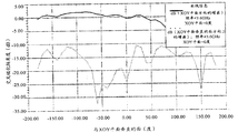
- FIG. 14 is a polarization diagram of a first radiating element in an embodiment of the present application.
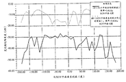
- FIG. 15 is a polarization diagram of a third radiating element in the embodiment of the present application.
- An embodiment of the present application provides an antenna and a mobile terminal, which are used to provide an antenna, where the antenna includes a first radiating unit, a second radiating unit, and a third radiating unit, and the antenna passes through pattern diversity and polarization diversity.
- the isolation between the radiating elements is greatly improved, and the antenna is compact in design, making full use of the clearance area of the grounding plate, effectively reducing the size of the antenna.
- MIMO Multiple-input Multiple-output
- both the transmitting end and the receiving end of the signal include multiple radiating elements. If the distance between the radiating elements is very long, the correlation between the radiating elements will be low, but in mobile terminals such as mobile phones, because of the small space, the radiating elements will not work relatively independently, but will generate strong electromagnetic coupling with each other.
- Coupling can be understood as: when there are more than two radiating elements in free space, one radiating unit is excluded The electromagnetic action generated by the self current is also affected by the electromagnetic action generated by the currents of other radiating elements. Especially when the radiating elements are close to each other, a complex interaction will occur between them, which is called mutual interaction. Coupling. Please refer to Figure 1 for a combined understanding.
- FIG. 1 is a schematic diagram showing the coupling when two radiating elements are arranged.
- the first radiating unit 110 and the second radiating unit 120 each receive a free-space incoming wave. Due to the characteristics of the antenna itself, the first radiating unit 110 is receiving.
- the wave will also act as a source to generate an excitation to radiate part of the energy, so that the signal received by the second radiating element 120 has a radiation wave radiated by the first radiating element 110 in addition to the spatial incoming wave.
- the second radiating element will generate an induced current to react to the first radiating element 110, and the two interact with each other, which is mutual coupling. Due to the electromagnetic induction (mutual coupling) between the radiating elements, the current on each radiating element changes, unlike the current distribution when placed in free space alone, thus seriously affecting the performance of the antenna.
- Isolation describes the degree of independence of the radiating elements. The smaller the coupling between the radiating elements, the greater the isolation. On the contrary, the greater the coupling between the antenna elements, the smaller the isolation. For example, in practical applications, the isolation is 15dB to meet engineering requirements.
- Pattern diversity The power radiated by the radiating element is generally non-uniform in all directions of the space, ie the antenna has directivity.
- the direction diagram refers to the function graph between the antenna radiation characteristics and the space coordinates, and is a graphical description method of the antenna directivity. Therefore, the pattern diversity can analyze the radiation characteristics of the radiation unit.
- Polarization diversity The two signals of the same source respectively have radio wave carriers with different polarization directions of the radiating elements, for example, vertical polarization and horizontal polarization.
- the two signals are independent of each other, are uncorrelated, and have different attenuation.
- Microstrip line is a microwave transmission line composed of a single conductor strip. It is suitable for making planar structure transmission lines of microwave integrated circuits.
- the utility model has the advantages of small volume, light weight, frequency bandwidth, high reliability and low manufacturing cost, high conductivity and good stability of the conductor.
- the mobile terminal 200 includes a housing 210.
- the housing 210 is provided with a dielectric substrate and an antenna 230.
- One side of the dielectric substrate is a grounding plate 220.
- FIG. A schematic diagram of the grounding plate 220 includes a clearance area 2201 at one end of the dielectric substrate.
- the dielectric substrate includes a top end, a bottom end, a left end, and a right end.
- the clearance area 2201 is located at the top end and the bottom end of the dielectric substrate, and the grounding area 220 is hollowed out to form the clearance area 2201, and the antenna 230 is disposed in the clearance area 2201.
- the mobile terminal further includes a processor, a transceiver, a display module, an input output module, or other electronic components.
- Antenna 230 is coupled to the transceiver.
- the grounding plate 220 and the antenna 230 are located at the top or bottom area of the mobile phone.
- the width of the clearing area of the grounding plate is 5 mm, and the length of the antenna is 19.48 mm.
- the layout of the entire MIMO antenna is very compact, which satisfies the design of the miniaturized MIMO antenna of the smart machine. Claim.
- One embodiment of the antenna in this embodiment of the present application includes:
- FIG. 4 is a schematic diagram of an antenna structure
- FIG. 5 is an enlarged schematic view of the antenna structure
- FIG. 6 is a schematic diagram of a clearance area.
- the antenna 230 includes three radiating elements and a closed loop 2304.
- the closed loop 2304 is placed in the clearance area 2201 of the ground plate and is connected to the ground plate.
- the clearance area 2201 may be rectangular.
- Place The closed loop 2304 may be a closed loop 2304 that is retained while the ground is hollowed out to form the clearance area 2201, or may be hollowed out on the ground plate to form a clearance area, and then A closed loop 2304 on the clearance area.
- the manner of forming the closed loop 2304 is not limited in this application.
- the three radiating elements are respectively a first radiating unit 2301, a third radiating unit 2303 and a second radiating unit 2302, and the first radiating unit 2301, the second radiating unit 2302 and the third radiating unit 2303 are connected by a microstrip line 2308 to form a radiation. body.
- the third radiating unit 2303 is disposed between the first radiating unit 2301 and the second radiating unit 2302.
- the three radiating elements are respectively connected to three different feeding points, and the radiator is excited by the three feeding points.
- a first feeding point 2305 is connected to the first radiating unit 2301
- a second feeding point 2306 is connected to the second radiating unit 2302
- a third feeding point 2307 is connected to the third radiating unit 2303.
- the shape of the closed loop 2304 can be rectangular. Specifically, it can be: "mouth” shape, "day” font, “ ⁇ ” font or “mesh” font, closed loop 2304
- the shape can be a regular shape, such as a rectangle, or an irregular shape.
- the closed loop 2304 is a closed structure and has two corresponding sides, the two sides being symmetrical structures, and the specific shape is not limited in the application.
- the "mouth” type and the " ⁇ ” type are taken as an example for description.
- the " ⁇ " type closed loop 2304 includes two left and right symmetrical sides, two upper and lower lateral sides and one middle one. The two vertical symmetrical sides are a first side 23041 and a second side 23042, respectively.
- the first radiating unit 2301 is placed on the first side 2304 of the closed loop 2304
- the second radiating unit 2302 is placed on the second side 23042 of the closed loop 2304
- the second side 2402 is Symmetrical sides of the first side edge 23041.
- the first side edge 23041 can be the left side of the " ⁇ " shaped closed loop 2304
- the second side edge 23042 can be the right side of the " ⁇ " shaped closed loop 2304.
- the two sides of the closed loop 2304 participate in the radiation of the first radiating unit 2301 and the second radiating unit 2302, that is, the first side 2304 participates in the radiation of the first radiating unit 2301, and the second side 23042 participates in the second radiating unit 2302.
- Radiation the main radiation direction of the first radiation unit 2301 is a first direction
- the main radiation direction of the second radiation unit 2302 is a second direction
- the first direction and the second direction are opposite.
- the main radiation direction of the first radiation unit 2301 is to the left
- the main radiation direction of the second radiation unit 2302 is to the right.
- the closed loop 2304 is coupled to the ground plate to neutralize the floor current of the first radiating element 2301 and the second radiating element 2302.
- the first radiating unit 2301 and the second radiating unit 2302 have good pattern diversity, and the degree of coupling between the first radiating unit 2301 and the second radiating unit 2302 is low.
- the first radiation unit 2301 is polarized in the same manner as the second radiation unit 2302.
- the first radiation unit 2301 and the third radiation unit 2303 are provided with a first preset spacing 2309, and the third radiation unit 2303 and the A second preset spacing 2310 is provided between the two radiating elements 2302.
- the first preset spacing 2309 and the second preset spacing 2310 are the same, and the first preset spacing 2309 and the second preset spacing 2310 may range from 0.1 to 3 mm.
- FIG. 7a is a schematic diagram of a preset distance when the shapes of the first radiating unit, the second radiating unit and the third radiating unit are regular shapes.
- the first preset pitch 2309 is between the right side of the first radiating element 2301 (near the side of the third radiating element 2303) and the left side of the third radiating element 2303 (near the side of the first radiating unit 2301) the distance. If the shapes of the first radiating unit, the second radiating unit and the third radiating unit are irregular shapes in practical applications, please understand with reference to FIG. 7b, the first radiating unit 2301 and the second radiating unit 2302 in FIG. 7b.
- the shape is merely illustrative and does not limit the specific shape of the radiating element.
- the first preset distance is: the sampling point on the right side of the first radiating unit 2301 to the third radiating unit An average of a plurality of line segments on the left side of 2303, the plurality of line segments being parallel to the ground plate, and the plurality of line segments are spaced apart by the same distance, that is, the vertical distance between the intervals between the sample points is the same.
- the first preset distance is described above, and the second preset distance is the same as the first preset distance, and details are not described herein.
- the two preset spacings 2310 are used to participate in the radiation of the third radiating element 2303, thereby also ensuring that the polarization of the third radiating element 2303 is orthogonal to the first radiating unit 2301 and the second radiating unit 2302. Thereby reducing the degree of coupling between the third radiating element 2303 and the first radiating unit 2301 and the second radiating unit 2302, improving the isolation between the third radiating element 2303 and the first radiating unit 2301 and the second radiating unit 2302 .
- the first side 2304 of the closed loop 2304 participates in the radiation of the first radiating element 2301
- the second side 23042 participates in the radiation of the second radiating unit 2302
- the first side 23041 broadens the radiation bandwidth of the first radiating element 2301
- the second side 23042 widens the radiation bandwidth of the second radiating element 2302.
- the closed loop 2304 does not participate in the radiation of the third radiating element 2303, and therefore, the bandwidth of the third radiating element 2303 is narrower than the bandwidth of the first radiating unit 2301 and the second radiating unit 2302.
- the bandwidth of the first radiating unit 2301 and the second radiating unit 2302 is 3.4 to 4.4 GHz
- the bandwidth of the third radiating unit 2303 is 3.5 to 3.75 GHz.
- the working frequency band of the antenna should cover these frequency bands and occupy as little space as possible.
- the radiant frequency band of the third radiating element 2303 can be adjusted by using an adjustable network, and the adjustable network is a circuit structure having an adjustable inductance or a capacitor.
- the circuit structure can be T-type or ⁇ . Type or L type, in actual application, the specific form of the circuit structure is not limited in this application.
- the adjustment range of the frequency band of the third radiation unit 2303 is within the range of the frequency band of the first radiation unit 2301 or the second radiation unit 2302.
- the length of the antenna in the embodiment of the present application is: the length of the antenna is: among them, v is the speed of light, and f 0 is the lowest frequency in the antenna band.
- the antenna operates at a minimum frequency of 3.85 GHz. Then, the length of the antenna is: 19.48 mm. It should be noted that it is understood in conjunction with FIGS. 8a and 8b.
- 8a is a schematic diagram of the length of the antenna when the first radiating unit 2301, the second radiating unit 2302, and the third radiating unit 2303 are in a regular shape. Referring to FIG. 8a, the distance between the leftmost side (e side) of the first radiating element 2301 and the rightmost side (f side) of the second radiating element 2302 is the length of the antenna. Referring to FIG. 8b, FIG.
- 8b is a schematic diagram of the length of the antenna when the shape of the first radiating element, the second radiating element and the third radiating element is irregular.
- a vertical line c passing through the leftmost point (point a) of the first radiating element 2301, a perpendicular d passing through the rightmost point (point b) of the second radiating element 2302, and between the perpendicular line c and the perpendicular d The distance is the length of the antenna.
- FIG. 9 is a schematic structural diagram of another embodiment of the antenna.
- the antenna further includes a bracket 2311.
- the first radiating unit 2301, the second radiating unit 2302 and the third radiating unit 2303 are disposed on the bracket 2311.
- the bracket 2311 is disposed on the grounding plate, and the shape of the upper surface of the bracket 2311 is three.
- Whole radiation unit The shape of the body is the same, and the area of the upper plane of the bracket 2311 is the same as the overall area of the three radiating elements, the shape of the lower plane of the bracket 2311 is the same as the shape of the clearance area, and the area of the lower plane of the bracket 2311 is the same as the area of the clearance area.
- the structure of the antenna is described above.
- the antenna is simulated by the electromagnetic simulation software, and the coupling of the antenna in the above embodiment is analyzed:
- FIG. 10 is a radiation pattern of the first radiation unit
- FIG. 11 is a radiation pattern of the second radiation unit.
- the radiation direction of the first radiation unit is opposite to the radiation direction of the second radiation unit.
- the antenna operates at 3.6 GHz, as can be seen from the radiation pattern of the first radiation unit and the radiation pattern of the second radiation unit, the first radiation unit and the second radiation unit are maintained in a good radiation pattern diversity, thereby enabling the antenna unit The coupling between the two is reduced, which improves the isolation between the antenna elements.
- Figure 12 shows the S-parameters of the first radiating element and the second radiating element.
- the bandwidth between the first radiating element and the second radiating element is 3.4 to 4.4 GHz, and the isolation is basically guaranteed to be 10 dB.
- Figure 13 shows that the bandwidth of the third radiating element is 3.5 to 3.75 GHz. The third radiating element maintains good isolation from the first radiating element and the second radiating element.
- the coupling between the radiating elements can also be analyzed by other analyses.
- an impedance method for example, an impedance method, a complex vector directivity function integration method, and the like.
- FIG. 14 is a schematic diagram showing the polarization mode of the first radiation unit
- FIG. 15 is a schematic diagram showing the polarization mode of the third radiation unit.
- the cross-polarization gain (Gain) of the first radiating element is greater than 10 dB.
- Phi represents the XOY plane
- Theta represents the plane perpendicular to the XOY plane
- the difference in Gain Theta in the Theta direction is the cross polarization isolation. It can be seen from FIG.
- the cross-polarization gain of the third radiating element (the difference between GainTheta and GainPhi) is greater than 10 dB. It can be known that the polarization mode of the first radiating element is orthogonal to the polarization mode of the third radiating element. Thereby, the polarization between the radiating elements is improved by the polarization diversity of the first radiating unit, the second radiating unit and the third radiating unit.
- the first radiating unit, the second radiating unit, and the third radiating unit are connected by a microstrip line, so that the first radiating unit, the second radiating unit, and the third radiating unit are integrated, and the first radiating unit
- the second radiating element and the third radiating element are disposed on the closed loop.
- the antenna is compact in design and makes full use of the clearance area of the grounding plate.
- the two sides of the closed loop respectively participate in the radiation of the first radiating unit and the second radiating unit, the main radiating direction of the first radiating unit is opposite to the main radiating direction of the second radiating unit, the first radiating direction and the second radiating direction Having good pattern diversity, reducing the coupling degree of the first radiating element and the second radiating element; the first preset pitch and the second preset pitch participate in the radiation of the third radiating element, so that the polarization of the third radiating element
- the method is orthogonal to the first radiating unit and the second radiating unit, and utilizes polarization diversity of the first radiating unit, the second radiating unit, and the third radiating unit, thereby effectively reducing the third radiating unit and the first radiating unit,
- the degree of coupling between the three radiating elements and the second radiating element improves the isolation.
- First radiation unit, second radiation unit, and third radiation unit first radiation unit, second radiation unit, and third radiation unit
Landscapes
- Engineering & Computer Science (AREA)
- Computer Networks & Wireless Communication (AREA)
- Variable-Direction Aerials And Aerial Arrays (AREA)
Abstract
L'invention concerne une antenne. L'antenne comprend : une première unité de rayonnement, une deuxième unité de rayonnement, une troisième unité de rayonnement et un anneau fermé. La première unité de rayonnement est connectée à un premier point d'alimentation, la deuxième unité de rayonnement est connectée à un deuxième point d'alimentation, et la troisième unité de rayonnement est connectée à un troisième point d'alimentation; et l'anneau fermé est placé dans une zone de dégagement d'une plaque de sol et est utilisé pour être relié à la plaque de sol. La première unité de rayonnement, la deuxième unité de rayonnement et la troisième unité de rayonnement forment un radiateur à travers une connexion de ligne micro-ruban, la troisième unité de rayonnement étant disposée entre la première unité de rayonnement et la deuxième unité de rayonnement. La première unité de rayonnement est placée sur un premier côté de l'anneau fermé, la seconde unité de rayonnement est placée sur un second côté de l'anneau fermé, le second côté étant opposé au premier côté. Une première distance prédéterminée est prévue entre la première unité de rayonnement et la troisième unité de rayonnement, et une deuxième distance prédéterminée est prévue entre la troisième unité de rayonnement et la deuxième unité de rayonnement. L'invention concerne également un terminal mobile.
Priority Applications (2)
| Application Number | Priority Date | Filing Date | Title |
|---|---|---|---|
| EP17830336.8A EP3471203B1 (fr) | 2016-07-20 | 2017-06-27 | Antenne et terminal mobile |
| US16/250,784 US11056781B2 (en) | 2016-07-20 | 2019-01-17 | Antenna and mobile terminal |
Applications Claiming Priority (2)
| Application Number | Priority Date | Filing Date | Title |
|---|---|---|---|
| CN201610578153.3 | 2016-07-20 | ||
| CN201610578153.3A CN107645038B (zh) | 2016-07-20 | 2016-07-20 | 一种天线及移动终端 |
Related Child Applications (1)
| Application Number | Title | Priority Date | Filing Date |
|---|---|---|---|
| US16/250,784 Continuation US11056781B2 (en) | 2016-07-20 | 2019-01-17 | Antenna and mobile terminal |
Publications (1)
| Publication Number | Publication Date |
|---|---|
| WO2018014702A1 true WO2018014702A1 (fr) | 2018-01-25 |
Family
ID=60991897
Family Applications (1)
| Application Number | Title | Priority Date | Filing Date |
|---|---|---|---|
| PCT/CN2017/090324 Ceased WO2018014702A1 (fr) | 2016-07-20 | 2017-06-27 | Antenne et terminal mobile |
Country Status (4)
| Country | Link |
|---|---|
| US (1) | US11056781B2 (fr) |
| EP (1) | EP3471203B1 (fr) |
| CN (1) | CN107645038B (fr) |
| WO (1) | WO2018014702A1 (fr) |
Families Citing this family (2)
| Publication number | Priority date | Publication date | Assignee | Title |
|---|---|---|---|---|
| CN109149082B (zh) * | 2018-07-18 | 2023-11-10 | 上海东洲罗顿通信股份有限公司 | 一种紧凑型mimo天线及包含其的通讯设备 |
| CN112751155B (zh) * | 2019-10-31 | 2022-04-05 | 华为技术有限公司 | 电子设备 |
Citations (6)
| Publication number | Priority date | Publication date | Assignee | Title |
|---|---|---|---|---|
| US20090135077A1 (en) * | 2004-11-05 | 2009-05-28 | Electronics And Telecommunications Research Institute | Multi-band internal antenna of symmetry structure having stub |
| CN103155281A (zh) * | 2010-10-15 | 2013-06-12 | 微软公司 | 用于移动手机及其他应用的回路天线 |
| CN103268987A (zh) * | 2013-05-10 | 2013-08-28 | 上海安费诺永亿通讯电子有限公司 | 一种小尺寸三频合一多频陶瓷天线 |
| CN103811869A (zh) * | 2012-11-08 | 2014-05-21 | 中兴通讯股份有限公司 | 一种多输入多输出天线系统及移动终端 |
| US20150048991A1 (en) * | 2012-04-20 | 2015-02-19 | Ethertronics, Inc. | Multi-feed loop antenna |
| CN204375977U (zh) * | 2015-01-16 | 2015-06-03 | 中兴通讯股份有限公司 | 一种多输入多输出天线系统 |
Family Cites Families (7)
| Publication number | Priority date | Publication date | Assignee | Title |
|---|---|---|---|---|
| CN101807748B (zh) | 2010-04-13 | 2012-10-31 | 湖南大学 | 一种宽带圆极化微带贴片天线 |
| CN201838715U (zh) * | 2010-07-29 | 2011-05-18 | 禾邦电子(苏州)有限公司 | 芯片型天线结构 |
| CN102623793A (zh) * | 2011-02-01 | 2012-08-01 | 华硕电脑股份有限公司 | 多输入输出天线系统 |
| GB201112839D0 (en) | 2011-07-26 | 2011-09-07 | Univ Birmingham | Multi-output antenna |
| CN202275941U (zh) | 2011-09-30 | 2012-06-13 | 中兴通讯股份有限公司 | 一种印刷式天线以及移动通信设备 |
| CN103138053B (zh) * | 2011-11-25 | 2016-03-30 | 上海德门电子科技有限公司 | 一种倒折双单极手机天线 |
| GB2528248A (en) * | 2014-07-10 | 2016-01-20 | Nokia Technologies Oy | Apparatus and methods for wireless communication |
-
2016
- 2016-07-20 CN CN201610578153.3A patent/CN107645038B/zh active Active
-
2017
- 2017-06-27 EP EP17830336.8A patent/EP3471203B1/fr active Active
- 2017-06-27 WO PCT/CN2017/090324 patent/WO2018014702A1/fr not_active Ceased
-
2019
- 2019-01-17 US US16/250,784 patent/US11056781B2/en active Active
Patent Citations (6)
| Publication number | Priority date | Publication date | Assignee | Title |
|---|---|---|---|---|
| US20090135077A1 (en) * | 2004-11-05 | 2009-05-28 | Electronics And Telecommunications Research Institute | Multi-band internal antenna of symmetry structure having stub |
| CN103155281A (zh) * | 2010-10-15 | 2013-06-12 | 微软公司 | 用于移动手机及其他应用的回路天线 |
| US20150048991A1 (en) * | 2012-04-20 | 2015-02-19 | Ethertronics, Inc. | Multi-feed loop antenna |
| CN103811869A (zh) * | 2012-11-08 | 2014-05-21 | 中兴通讯股份有限公司 | 一种多输入多输出天线系统及移动终端 |
| CN103268987A (zh) * | 2013-05-10 | 2013-08-28 | 上海安费诺永亿通讯电子有限公司 | 一种小尺寸三频合一多频陶瓷天线 |
| CN204375977U (zh) * | 2015-01-16 | 2015-06-03 | 中兴通讯股份有限公司 | 一种多输入多输出天线系统 |
Also Published As
| Publication number | Publication date |
|---|---|
| US11056781B2 (en) | 2021-07-06 |
| CN107645038B (zh) | 2019-11-29 |
| US20190157751A1 (en) | 2019-05-23 |
| EP3471203B1 (fr) | 2020-12-16 |
| EP3471203A4 (fr) | 2019-07-17 |
| EP3471203A1 (fr) | 2019-04-17 |
| CN107645038A (zh) | 2018-01-30 |
Similar Documents
| Publication | Publication Date | Title |
|---|---|---|
| Desai et al. | Compact wideband four element optically transparent MIMO antenna for mm-wave 5G applications | |
| CN108736162B (zh) | 一种适用于5g终端装置的新型天线单元 | |
| US8659500B2 (en) | Multi-antenna for a multi-input multi-output wireless communication system | |
| CN110534924A (zh) | 天线模组和电子设备 | |
| US8878737B2 (en) | Single feed planar dual-polarization multi-loop element antenna | |
| CN106450752B (zh) | 一种用于智能手机实现高隔离度的mimo天线 | |
| CN106935952B (zh) | 双极化天线和通信设备 | |
| CN101572351B (zh) | 多输入多输出天线 | |
| KR20120138758A (ko) | 강화된 안테나 아이솔레이션을 위한 새로운 전류 분포 및 방사 패턴을 가진 안테나 | |
| CN104901006B (zh) | 基于分形结构的多频带微带mimo天线 | |
| CN109037933B (zh) | 双频三极化mimo天线及无线通信设备 | |
| CN108649330A (zh) | 一种适用于5g移动终端的八单元mimo天线 | |
| CN109301486B (zh) | 用于5g移动通信的单层贴片式微波毫米波跨频段双频双极化辐射单元 | |
| CN112751168A (zh) | 天线模组及电子设备 | |
| CN110233349B (zh) | 多输入多输出天线及终端设备 | |
| CN108736148B (zh) | 天线装置与电子设备 | |
| Pandurangan et al. | Various mutual coupling reduction techniques for 5G: MIMO antenna | |
| KR20220111555A (ko) | 안테나 모듈 및 이를 포함하는 전자 장치 | |
| CN116435775B (zh) | 一种天线结构和电子设备 | |
| US11056781B2 (en) | Antenna and mobile terminal | |
| Al-Bawri et al. | Multilayer base station antenna at 3.5 GHz for future 5G indoor systems | |
| Sharma et al. | Analysis of MIMO antennas with parasitic elements for wireless applications | |
| Muhsin et al. | A compact high isolation four elements MIMO antenna system for 5G mobile devices | |
| CN111244609A (zh) | 多输入多输出天线系统和移动终端 | |
| WO2018119946A1 (fr) | Système d'antenne à entrées multiples et sorties multiples et terminal mobile |
Legal Events
| Date | Code | Title | Description |
|---|---|---|---|
| 121 | Ep: the epo has been informed by wipo that ep was designated in this application |
Ref document number: 17830336 Country of ref document: EP Kind code of ref document: A1 |
|
| ENP | Entry into the national phase |
Ref document number: 2017830336 Country of ref document: EP Effective date: 20190109 |
|
| NENP | Non-entry into the national phase |
Ref country code: DE |