WO2018016013A1 - Appareil d'épissage et procédé d'épissage - Google Patents
Appareil d'épissage et procédé d'épissage Download PDFInfo
- Publication number
- WO2018016013A1 WO2018016013A1 PCT/JP2016/071191 JP2016071191W WO2018016013A1 WO 2018016013 A1 WO2018016013 A1 WO 2018016013A1 JP 2016071191 W JP2016071191 W JP 2016071191W WO 2018016013 A1 WO2018016013 A1 WO 2018016013A1
- Authority
- WO
- WIPO (PCT)
- Prior art keywords
- splicing
- tape
- cam
- carrier tape
- pressing
- Prior art date
- Legal status (The legal status is an assumption and is not a legal conclusion. Google has not performed a legal analysis and makes no representation as to the accuracy of the status listed.)
- Ceased
Links
Images












Classifications
-
- B—PERFORMING OPERATIONS; TRANSPORTING
- B65—CONVEYING; PACKING; STORING; HANDLING THIN OR FILAMENTARY MATERIAL
- B65H—HANDLING THIN OR FILAMENTARY MATERIAL, e.g. SHEETS, WEBS, CABLES
- B65H19/00—Changing the web roll
- B65H19/10—Changing the web roll in unwinding mechanisms or in connection with unwinding operations
- B65H19/18—Attaching, e.g. pasting, the replacement web to the expiring web
- B65H19/1842—Attaching, e.g. pasting, the replacement web to the expiring web standing splicing, i.e. the expiring web being stationary during splicing contact
- B65H19/1852—Attaching, e.g. pasting, the replacement web to the expiring web standing splicing, i.e. the expiring web being stationary during splicing contact taking place at a distance from the replacement roll
-
- B—PERFORMING OPERATIONS; TRANSPORTING
- B65—CONVEYING; PACKING; STORING; HANDLING THIN OR FILAMENTARY MATERIAL
- B65H—HANDLING THIN OR FILAMENTARY MATERIAL, e.g. SHEETS, WEBS, CABLES
- B65H21/00—Apparatus for splicing webs
-
- H—ELECTRICITY
- H05—ELECTRIC TECHNIQUES NOT OTHERWISE PROVIDED FOR
- H05K—PRINTED CIRCUITS; CASINGS OR CONSTRUCTIONAL DETAILS OF ELECTRIC APPARATUS; MANUFACTURE OF ASSEMBLAGES OF ELECTRICAL COMPONENTS
- H05K13/00—Apparatus or processes specially adapted for manufacturing or adjusting assemblages of electric components
- H05K13/02—Feeding of components
- H05K13/0215—Interconnecting of containers, e.g. splicing of tapes
-
- H—ELECTRICITY
- H05—ELECTRIC TECHNIQUES NOT OTHERWISE PROVIDED FOR
- H05K—PRINTED CIRCUITS; CASINGS OR CONSTRUCTIONAL DETAILS OF ELECTRIC APPARATUS; MANUFACTURE OF ASSEMBLAGES OF ELECTRICAL COMPONENTS
- H05K13/00—Apparatus or processes specially adapted for manufacturing or adjusting assemblages of electric components
- H05K13/04—Mounting of components, e.g. of leadless components
- H05K13/0417—Feeding with belts or tapes
- H05K13/0419—Feeding with belts or tapes tape feeders
-
- B—PERFORMING OPERATIONS; TRANSPORTING
- B65—CONVEYING; PACKING; STORING; HANDLING THIN OR FILAMENTARY MATERIAL
- B65H—HANDLING THIN OR FILAMENTARY MATERIAL, e.g. SHEETS, WEBS, CABLES
- B65H2301/00—Handling processes for sheets or webs
- B65H2301/40—Type of handling process
- B65H2301/44—Moving, forwarding, guiding material
- B65H2301/449—Features of movement or transforming movement of handled material
- B65H2301/4493—Features of movement or transforming movement of handled material intermittent
-
- B—PERFORMING OPERATIONS; TRANSPORTING
- B65—CONVEYING; PACKING; STORING; HANDLING THIN OR FILAMENTARY MATERIAL
- B65H—HANDLING THIN OR FILAMENTARY MATERIAL, e.g. SHEETS, WEBS, CABLES
- B65H2301/00—Handling processes for sheets or webs
- B65H2301/40—Type of handling process
- B65H2301/46—Splicing
- B65H2301/462—Form of splice
- B65H2301/4622—Abutting article or web portions, i.e. edge to edge
- B65H2301/46222—Abutting article or web portions, i.e. edge to edge involving double butt splice, i.e. adhesive tape applied on both sides of the article or web portions
-
- B—PERFORMING OPERATIONS; TRANSPORTING
- B65—CONVEYING; PACKING; STORING; HANDLING THIN OR FILAMENTARY MATERIAL
- B65H—HANDLING THIN OR FILAMENTARY MATERIAL, e.g. SHEETS, WEBS, CABLES
- B65H2301/00—Handling processes for sheets or webs
- B65H2301/40—Type of handling process
- B65H2301/46—Splicing
- B65H2301/463—Splicing splicing means, i.e. means by which a web end is bound to another web end
- B65H2301/4631—Adhesive tape
-
- B—PERFORMING OPERATIONS; TRANSPORTING
- B65—CONVEYING; PACKING; STORING; HANDLING THIN OR FILAMENTARY MATERIAL
- B65H—HANDLING THIN OR FILAMENTARY MATERIAL, e.g. SHEETS, WEBS, CABLES
- B65H2403/00—Power transmission; Driving means
- B65H2403/50—Driving mechanisms
- B65H2403/51—Cam mechanisms
-
- B—PERFORMING OPERATIONS; TRANSPORTING
- B65—CONVEYING; PACKING; STORING; HANDLING THIN OR FILAMENTARY MATERIAL
- B65H—HANDLING THIN OR FILAMENTARY MATERIAL, e.g. SHEETS, WEBS, CABLES
- B65H2701/00—Handled material; Storage means
- B65H2701/10—Handled articles or webs
- B65H2701/19—Specific article or web
- B65H2701/1942—Web supporting regularly spaced non-adhesive articles
Definitions
- the present invention relates to a splicing device and a splicing method for connecting carrier tapes with a splicing tape.
- a reel on which a carrier tape storing a plurality of electronic components (hereinafter simply referred to as “components”) is wound is loaded into a tape feeder. Then, by driving a sprocket that engages with a feed hole drilled in the carrier tape, the carrier tape is sent out in a fixed quantity and parts are sequentially supplied to the parts supply position. Installing.
- first carrier tape the terminal portion of the carrier tape
- second carrier tape a carrier tape wound on another reel containing various types of components
- the first carrier tape and the second carrier tape are sent in directions approaching each other from both sides of the device, and the end portion of the first carrier tape and the start end portion of the second carrier tape are spliced. Position to position. Then, the front-side splicing tape and the back-side splicing tape are pressed against and attached to the front and back surfaces across the first carrier tape and the second carrier tape positioned at the splicing position by cam drive.
- the splicing tape may be insufficiently attached to the carrier tape and peel off.
- This problem can be dealt with by driving the cam at a low speed and increasing the pressing time of the splicing tape against the carrier tape, but the splicing cycle time becomes longer.
- the cam becomes large and the splicing device becomes large.
- An object of the present invention is to provide a splicing device and a splicing method that can securely attach a splicing tape to a carrier tape.
- a splicing device of the present invention is a splicing device for connecting a first carrier tape having a component storage cavity and a second carrier tape by a first splicing tape and a second splicing tape, A positioning device for sending the first carrier tape and the second carrier tape in a direction approaching each other to position the end of the first carrier tape and the end of the second carrier tape at a splicing position; A first pressing member that presses the splicing tape against one surface of the first carrier tape and the second carrier tape across the first carrier tape and the second carrier tape positioned at the splicing position; 2 Splicing tape A second pressing member that presses against the other surface of the first carrier tape and the second carrier tape across the first carrier tape and the second carrier tape positioned at the icing position, and the first operation by a series of operations.
- a driving device that reciprocally moves the pressing surface of the pressing member and the pressing surface of the second pressing member toward and away from each other; and the first pressing member and the second pressing device by the series of operations of the driving device.
- a control device for temporarily stopping the series of operations of the driving device in a pressing state in which the pressing member presses the first splicing tape and the second splicing tape against the first carrier tape and the second carrier tape; Prepare.
- the splicing device is a series of operations of the driving device that drives the first and second pressing members in the pressing state in which the first and second pressing members press the splicing tape against the first and second carrier tapes. Therefore, the pressing time of the splicing tape against the first and second carrier tapes can be extended. Therefore, the splicing tape can be securely attached to the first and second carrier tapes.
- the splicing method of the present invention is a splicing method for connecting a first carrier tape having a component storage cavity and a second carrier tape by the first splicing tape and the second splicing tape, A positioning step of feeding the first carrier tape and the second carrier tape in a direction approaching each other to position an end portion of the first carrier tape and an end portion of the second carrier tape at a splicing position; By a series of operations, the first splicing tape is pressed against one surface of the first carrier tape and the second carrier tape across the first carrier tape and the second carrier tape positioned at the splicing position, The second splicing tape A pressing step of pressing against the other surface of the first carrier tape and the second carrier tape across the first carrier tape and the second carrier tape positioned at the splicing position, and the series of operations of the driving device And a stopping step of temporarily stopping the series of operations of the driving device in a pressing state in which the first splicing tape and the second splicing tape are pressed
- FIG. 3 is a cross-sectional view taken along line 3-3 in FIG. It is a figure which shows the sticking state of the splicing tape with respect to the base tape in a splicing tape supply member. It is a figure which shows the state which opened the cover body of the splicing apparatus. It is a figure which shows the state which mounted
- FIG. 10 It is a perspective view which shows the joining apparatus which joins a splicing tape to a carrier tape. It is a top view which shows a joining apparatus. It is the front view seen from the arrow 10 direction of FIG. It is the right view seen from the arrow 11 direction of FIG. It is the left view seen from the arrow 12 direction of FIG. It is a figure which shows the 1st cam groove formed in the cam drum of a joining apparatus. It is a cam diagram of a 1st cam groove. It is a figure which shows the 2nd cam groove formed in the cam drum of a joining apparatus. It is a cam diagram of a 2nd cam groove. It is a figure which shows the 3rd cam groove formed in the cam drum of a joining apparatus.
- FIG. 1 It is a cam diagram of a 3rd cam groove. It is a figure which shows the 4th cam groove formed in the cam drum of a joining apparatus. It is a cam diagram of a 4th cam groove. It is the figure which looked at the sensor arrange
- FIG. 1 It is a cam diagram of a 3rd cam groove. It is a figure which shows the 4th cam groove formed in the cam drum of a joining apparatus. It is a cam diagram of a 4th cam groove. It is the figure which looked at the sensor arrange
- 24 is a cross-sectional view taken along line 24-24 of FIG. It is a figure which shows the state which a 1st lifting platform and a 2nd lifting platform raise. It is a figure which shows the state in which the turntable provided in a 2nd lifting platform turns. It is a figure which shows the state which the turntable provided in the 2nd lifting platform completed the turn. It is a figure which shows the state which is pressing the carrier tape and the splicing tape with a 1st lifting platform and a 2nd lifting platform.
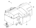
- the splicing device 20 includes a current reel carrier tape T (see FIGS. 2 and 3) inserted from both sides of the device main body 21 in a state in which an openable / closable lid 22 is closed.
- the carrier tape T of the next reel is spliced by the splicing tape 30 (see FIG. 4) which is abutted at the center of the apparatus main body 21 and is supplied by the splicing tape supply member TT (see FIG. 4).
- the carrier tape T is formed long and narrow with a predetermined width, and a large number of cavities Ct are arranged at a constant pitch interval Pc in the longitudinal direction.
- the components e to be mounted on the board are respectively stored.
- the upper part of the cavity Ct is opened, and is covered with a cover tape Tt attached to the surface of the carrier tape T.
- feed holes Hc are formed at the same pitch interval Pc as the cavity Ct or at a pitch interval 2Pc that is twice the cavity Ct, and these feed holes Hc are at a fixed position with respect to the cavity Ct. Placed in a relationship.
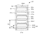
- the splicing tape supply member TT has a three-layer structure including a splicing tape 30, a base tape 31, and a top film 32.
- the splicing tape 30 is composed of a pair of splicing tapes 30a and 30b on the upper surface of the continuous base tape 31 and for the front surface and the back surface that are bonded to both surfaces of the two carrier tapes T. That is, the splicing tape 30 includes a surface splicing tape 30a (first splicing tape) bonded to the front surface side of the two carrier tapes T and a back surface splicing tape 30b (bonded to the back surface side of the two carrier tapes T).
- the second splicing tape) is a set.
- a set of splicing tapes 30 for the front and back surfaces has a constant pitch in the longitudinal direction of the base tape 31 while maintaining a fixed positional relationship with the feed holes 31a drilled at a fixed pitch interval on both sides of the base tape 31. Affixed with an interval Pd. Further, the pair of splicing tapes 30 is arranged with a predetermined interval Pd1 with the front splicing tape 30a as the leading side. A continuous top film 32 is adhered to the upper surface of the splicing tape 30. Metal powder is embedded in the splicing tape 30, and the splicing device 20 detects the splicing tape 30 by a tape detection sensor (not shown) that can detect metal.
- the adhesive force between the top film 32 and the base tape 31 bonded to both surfaces of the splicing tape 30 is stronger than the base tape 31, and even if the top film 32 is peeled off from the splicing tape 30, the splicing tape 30. Is prevented from being peeled off from the base tape 31.
- the adhesive strength thereof is stronger than the adhesive strength to the base tape 31, and the base tape 31 is peeled off from the splicing tape 30. It is easy.
- the width direction dimension of the base tape 31 is larger than the width direction dimension of the top film 32, and both ends of the base tape 31 in the width direction protrude from both ends of the top film 32 in the width direction.
- the width direction dimension of the splicing tape 30 is equal to the width direction dimension of the top film 32, and the splicing tape 30 is affixed to the base tape 31 inside the feed hole 31a.
- a plurality of positioning holes 31b are formed in the base tape 31 along the width direction of the base tape 31 at positions close to the surface splicing tape 30a at the same pitch interval as the feed holes Hc formed in the carrier tape T.
- a plurality of positioning holes 30b1 are formed in the back surface splicing tape 30b along the width direction of the base tape 31 through the base tape 31 at the same pitch intervals as the feed holes Hc formed in the carrier tape T.
- the feed holes 31a and positioning holes 31b formed in the base tape 31 are aligned with the formation of the positioning holes 30b1 in the back surface splicing tape 30b after the splicing tape 30 is attached to the base tape 31 at a predetermined position. Formed by a punching press or the like.
- the splicing device 20 includes first and second tape feeding devices 50 and 51, first and second cutting devices 54 and 55, and first and second taking-in.
- the two carrier tapes T to be spliced are referred to as first and second carrier tapes T1 and T2.
- the first and second tape feeders 50 and 51 are configured so that the first and second transport paths 60a and 60b move the first and second carrier tapes T1 and T2 from the side surfaces of the apparatus main body 21 toward the center.
- the predetermined first and second cutting positions of the first and second carrier tapes T1 and T2 are sequentially positioned at the first and second cutting positions Lc1 and Lc2 and the splicing position LS. That is, the first and second tape feeders 50 and 51 function as first and second positioning devices.
- the first and second cutting devices 54 and 55 cut the first and second unnecessary portions at the first and second cutting positions of the first and second carrier tapes T1 and T2.
- the first cutting position of the first carrier tape T1 for example, an intermediate position between the cavity Ct where the part e of the first carrier tape T1 is present and the empty cavity Ct where the part e is absent is selected.
- the first and second take-in devices 56 and 57 take in the first and second unnecessary portions to be cut of the first and second carrier tapes T1 and T2, respectively. That is, the first carrier tape T1 including the continuous empty cavities Ct is taken into the first take-in device 56 as a first unnecessary portion and discarded. The same applies to the second unnecessary portion of the second carrier tape T.
- the supply reel holding unit 34 is attached to the apparatus main body 21 and rotatably supports the supply reel 33 on which the splicing tape supply member TT is wound in a roll shape.
- the supply reel holding unit 34 is pressed against the supply reel 33 by a predetermined frictional force generated by a spring force, and the supply reel holding unit 34 restricts the rotation of the supply reel 33 with respect to the supply reel holding unit 34.
- the supply reel 33 can rotate with respect to the supply reel holding portion 34.
- the top film conveying device 35 includes a roller 352a that sandwiches and feeds the top film 32 and a motor 352b that rotates the roller 352a, and is disposed below the supply reel 33.
- the top film transport device 35 sends out the top film 32 folded back in the direction opposite to the transport direction of the splicing tape supply member TT by the operator and peels off the top film 32 from the base tape 31.
- the splicing tape supply member conveying device 36 includes a sprocket 46 for feeding and a stepping motor 47, and sends out the base tape 31 from which the splicing tape 30 has been peeled off. That is, a plurality of engagement teeth 46a are formed in the feed sprocket 46 at equal angular intervals in the circumferential direction at the same pitch as the pitch of the feed holes 31a drilled in the base tape 31.
- the base tape 31 from which the top film 32 has been peeled off that is, the base tape 31 to which a large number of splicing tapes 30 are attached with the adhesive surface facing upward passes through the joining device 58 so as to cross the center of the splicing position LS.
- the feed hole 31 a is engaged with the engagement teeth 46 a of the feed sprocket 46.
- the stepping motor 47 is connected to the feeding sprocket 46, and feeds the base tape 31 engaged with the engaging teeth 46a by a unit amount by being driven by one pitch.
- the stepping motor 47 is returned to the origin when the power is turned on, and is positioned so that the engaging teeth 46a of the feed sprocket 46 are always located at the apex.
- the stepping motor 47 can be appropriately restricted in rotation by, for example, rotation restricting means 47a such as a servo lock device or by applying excitation.
- rotation restricting means 47a such as a servo lock device or by applying excitation.
- the joining device 58 is provided between the first cutting device 54 and the second cutting device 55.
- the joining device 58 detects the splicing tapes 30a and 30b installed at a position separated from the splicing position LS by a certain distance on the front side of the splicing position LS below the base tape 31 fed from the supply reel 33.
- a tape detection sensor (not shown) is provided.
- the joining device 58 is fed from the left and right sides of the device main body 21 at the intermediate splicing position LS between the first and second transport paths 60a and 60b, and the first and second cutting points are brought into contact with each other.
- the first and second carrier tapes T ⁇ b> 1 and T ⁇ b> 2 are connected by a splicing tape 30 that is fed from an upper direction orthogonal to the first and second carrier tapes T ⁇ b> 2 and positioned based on a detection signal of a tape detection sensor.
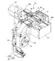
- the joining device 58 includes a first lifting platform 91, a support plate 97, a second lifting platform 101, a swivel platform 103, and the like.
- the leg portion 92 of the first lifting platform 91 is guided and supported so as to be movable up and down.
- a first pressing member 91a is provided on the first lifting platform 91, and the first pressing member 91a is provided on both sides with the joining position (butting position) of the first and second carrier tapes T1 and T2 as the center.
- the first positioning pins 93 and 94 that are engageable with the positioning holes 30b1 and 31b formed in the splicing tape 30 and the feed holes Hc of the first and second carrier tapes T1 and T2 are first, It protrudes along the feeding direction of the second carrier tapes T1, T2.
- Each pitch of these two sets of first positioning pins 93 and 94 is determined to be twice the pitch interval Pc of the feed holes Hc of the first and second carrier tapes T1 and T2.
- pin holes 95 are formed between the first positioning pins 93 and 94 in the first lifting platform 91, and second positioning pins 105 on the swivel base 103 side which will be described later enter into these pin holes 95. it can.
- a movable base 96 is guided and supported by the apparatus main body 21 in a horizontal direction perpendicular to the longitudinal direction of the first and second carrier tapes T1 and T2, and the first positioning pins 93 are supported on the movable base 96.
- a support plate 97 is attached.
- a U-shaped groove 98 that can accommodate the first positioning pins 93 and 94 is formed at the tip of the support plate 97, and the support plate 97 has a retracted end from which the groove 98 is separated from the first positioning pins 93 and 94.
- the groove 98 can move back and forth between the forward ends that receive the first positioning pins 93 and 94.
- the end portion of the first carrier tape T1 and the start end portion of the second carrier tape T2 are supported.
- leg portion 102 of the second lifting platform 101 is guided and supported by the apparatus main body 21 so as to be movable up and down.
- a swivel 103 is supported at both ends so that it can turn 180 degrees around a pivot shaft 104 parallel to the longitudinal direction of the first and second carrier tapes T1, T2.
- the swivel base 103 is provided with a second pressing member 103a at a position offset from the turning center, and the second pressing member 103a is provided with a plurality of second positioning pins 105 and pin holes 106.
- the second positioning pins 105 are arranged at corresponding positions between the first positioning pins 93 and 94 provided on the first lifting platform 91 and can enter the pin holes 95 provided on the first lifting platform 91.
- the pin holes 106 are arranged at corresponding positions between the second positioning pins 105, and the first positioning pins 93 and 94 provided on the first lifting platform 91 can enter.
- the second positioning pin 105 is engaged with the feed holes Hc of the first and second carrier tapes T1 and T2 and the positioning holes 31b and 30b1 of the splicing tape 30 which are positioned at the splicing position LS by the 180 degree rotation of the swivel base 103.
- the positional relationship between the first and second carrier tapes T1 and T2 and the splicing tape 30 connecting them is kept constant.
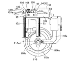
- a pinion 107 is attached to the pivot shaft 104 of the swivel base 103.
- a movable base 109 is movable in a horizontal direction perpendicular to the transport direction of the first and second carrier tapes T1 and T2 when a rack 108 meshing with the pinion 107 is attached. Mounted on. As a result, when the movable table 109 is moved, the swivel base 103 is swung by the rack and pinion mechanism including the pinion 107 and the rack 108.
- the pressing surface 103b of the second pressing member 103a of the swivel 103 and the pressing surface 91b of the first pressing member 91a of the first elevator 91 are moved.
- the first, second carrier tapes T1, T2 and the splicing tape 30 are finally connected between the pressing surface 103b of the second pressing member 103a and the pressing surface 91b of the first pressing member 91a. It is pinched and connected to each other.
- a cam drum 110 (corresponding to “driving device” or “cam” of the present invention) is supported on the apparatus main body 21 so as to be rotatable about an axis parallel to the turning center of the swivel base 103, and a drive motor 120 ( It is rotated at a low speed in a fixed direction by the “driving device” and “cam driving device” of the invention.
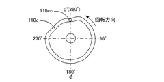
- Two cam grooves 110a, 110b, 110c, and 110d are formed on both surfaces of the cam drum 110 in an endless manner in the circumferential direction.
- a first follower roller 110cc (supported by a leg 92 of the first elevator 91) is provided.
- the 1st cam groove 110c is provided in order to raise / lower the 1st raising / lowering stand 91.
- FIG. That is, as shown in FIGS. 13 and 14, when the cam drum 110 has a cam phase angle of 0 °, the first lifting platform 91 is located at the bottom dead center.
- the first lifting platform 91 rises and reaches the top dead center.
- the first elevator 91 is located at the top dead center until the cam drum 110 rotates and the cam phase angle reaches 265 °. Further, when the cam drum 110 rotates and the cam phase angle reaches 305 °, the first lifting platform 91 descends and reaches the bottom dead center, and the cam drum 110 rotates and the cam phase angle reaches 360 ° (0 °). Until it reaches, the 1st lifting platform 91 is located in the bottom dead center.
- the second cam groove 110d (corresponding to the “second cam” of the present invention) is pivotally supported by a connecting member 109b having a follower 109a that contacts the movable base 109.
- the follower roller 110dd (corresponding to the “second cam” of the present invention) is engaged.
- the movable base 109 is always pulled to the left in FIG. 12 by the tension spring 109c.
- the second cam groove 110d is provided for turning the turntable 103. That is, as shown in FIGS. 15 and 16, when the cam drum 110 has a cam phase angle of 0 °, the swivel base 103 is in a state in which the second positioning pin 105 faces upward (hereinafter referred to as “turning upward”).
- the swivel base 103 starts swiveling in the opposite direction, and when the cam drum 110 rotates and the cam phase angle reaches 305 °, the swivel base 103 turns upward. Until the cam drum 110 rotates and the cam phase angle reaches 360 ° (0 °), the swivel base 103 maintains the turning upward state.
- a third follower roller 110aa (supported by the leg portion 102 of the second lifting platform 101).
- the third cam groove 110a is provided to raise and lower the second lifting platform 101. That is, as shown in FIGS. 17 and 18, when the cam drum 110 has a cam phase angle of 0 °, the second lifting platform 101 is located at the bottom dead center.
- the second lifting / lowering platform 101 rises and reaches top dead center.
- the second lifting platform 101 is located at the top dead center until the cam drum 110 rotates and the cam phase angle reaches 110 °. Further, when the cam drum 110 rotates and the cam phase angle reaches 145 °, the second lifting platform 101 descends to reach the bottom dead center, and the cam drum 110 rotates to reach the cam phase angle of 215 °. 2
- the elevator 101 is located at the bottom dead center.
- the cam drum 110 rotates and the cam phase angle reaches 235 °
- the second lifting platform 101 rises to reach a height h lower than the top dead center, and the cam drum 110 rotates and the cam phase angle becomes 280 °.
- the second lifting platform 101 is located at the height h until it reaches. Further, when the cam drum 110 rotates and the cam phase angle reaches 305 °, the second lifting platform 101 descends and reaches the bottom dead center, and the cam drum 110 rotates and the cam phase angle reaches 360 ° (0 °). Until it reaches, the 2nd lifting platform 101 is located in the bottom dead center.
- the movable base 109 is always pulled to the left in FIG. 12 by the tension spring 109c and is in contact with the follower 109a of the connecting member 109b. Therefore, even when the connecting member 109b horizontally moves the movable table 109 along the second cam groove 110d, the movable table 109 and the second elevator table 101 can move up and down along the third cam groove 110a.
- the fourth cam groove 110 b (corresponding to the “fourth cam” of the present invention) is pivotally supported by an arm 96 a extending from a movable base 96 connected to a support plate 97.
- Four follower rollers 110bb (corresponding to the “fourth cam” of the present invention) are engaged.
- the fourth cam groove 110b is provided to advance and retract the support plate 97 in the horizontal direction. That is, as shown in FIGS. 19 and 20, when the cam drum 110 has a cam phase angle of 0 °, the support plate 97 is positioned at the forward end where the groove 98 accommodates the first positioning pins 93 and 94.
- the support plate 97 starts to retreat, and when the cam drum 110 rotates and the cam phase angle reaches 80 °, the support plate 97 98 reaches the retracted end where the first positioning pins 93 and 94 are separated.
- the support plate 97 is positioned at the retracted end until the cam drum 110 rotates and the cam phase angle reaches 310 °. Further, when the cam drum 110 rotates, the support plate 97 starts to advance, and when the cam phase angle reaches 360 ° (0 °), the support plate 97 reaches the advance end.
- the cam drum 110 when the cam drum 110 is rotated from the cam phase angle of 0 °, the first, second, third, and fourth cam grooves 110c, 110d, 110a, and 110b are engaged with the first, second, and third cam grooves, respectively.
- the third and fourth follower rollers 110cc, 110dd, 110aa, 110bb Via the third and fourth follower rollers 110cc, 110dd, 110aa, 110bb, the first and second lifting platforms 91, 101 are moved up and down, the support plate 97 is moved back and forth, and the swiveling table 103 is swung (movable table). 96 horizontal movements) are performed in conjunction with each other.
- the cam drum 110 rotates once, and performs a series of operations of the first and second lifting platforms 91 and 101, the support plate 97, and the swivel base 103 (movable base 96) once.
- the cam refers to the cam drum 110, the first, second, third, and fourth cam grooves 110c, 110d, 110a, and 110b and the first, second, third, and fourth follower rollers 110cc and 110dd. , 110aa, 110bb.
- the first lifting platform 91 and the second lifting platform 101 replace the front splicing tape 30a and the rear splicing tape 30b with the first carrier tape T1 and the second carrier tape by a series of cam operations.
- the series of cam operations are temporarily stopped by temporarily stopping the drive motor 120, and the series of cam operations is resumed after a predetermined time set in the control device 59 has elapsed.
- the splicing tape 30 can be sufficiently adhered to the carrier tape T.
- the predetermined time for the temporary stop can be adjusted according to the type of the splicing tape 30 (type of adhesive material), the type of the carrier tape T, the outside air temperature when performing splicing, and the like, and is set in the control device 59.
- the pressing state is continued in a predetermined angle range during one rotation of the cam drum 110, in this example, in a range where the cam phase angle is 145 ° -215 °.
- the control device 59 temporarily stops the series operation of the cam by temporarily stopping the drive motor 120 while the cam is operating in the range of 145 ° to 215 ° in the series operation.
- the timing for temporarily stopping the drive motor 120 may be when the cam is located at the center of a predetermined angle range, in this example, the cam phase angle is 180 ° (hereinafter referred to as “drive stop point”). This is because the pressing state is maintained even when the timing of temporary stop of the drive motor 120 varies.
- the temporary stop time of the drive motor 120 is set according to the adhesive force of the splicing tape 30 to the carrier tape T.
- the suspension time of the drive motor 120 is measured by a timer built in the control device 59.
- the apparatus main body 21 is provided with an origin sensor 111 and a splicing sensor 112 as shown in FIGS. 21A and 21B.
- the origin sensor 111 is a sensor that detects the original positions (cam phase angle 0 °) of the first and second elevators 91 and 101, the support plate 97, and the swivel base 103 (movable base 96).
- the origin sensor 111 is a photoelectric sensor having a light emitting element 111a and a light receiving element 111b.
- the light emitting element 111a and the light receiving element 111b are arranged on both sides of the cam drum 110 so that the sensor light can pass through a through hole 111c formed at a cam phase angle of 0 ° of the cam drum 110.
- the splicing sensor 112 is a sensor that detects a drive stop point (cam phase angle 180 °) of the cam drum 110, that is, a timing for temporarily stopping the drive motor 120.
- the splicing sensor 112 is a photoelectric sensor having a light emitting element 112a and a light receiving element 112b.
- the light emitting element 112a and the light receiving element 112b are arranged on both sides of the cam drum 110 so that the sensor light can pass through a through hole 112c formed at a cam phase angle of 180 ° of the cam drum 110.
- the through hole 111 c and the through hole 112 c are formed at positions shifted in the radial direction of the cam drum 110 so that the sensor light from the origin sensor 111 and the sensor light from the splicing sensor 112 do not interfere with each other.
- the control device 59 passes the first and second carrier tapes T1 and T2 inserted from both side surfaces of the device main body 21 by the first and second tape feeding devices 50 and 51 along the first and second transport paths 60a and 60b.
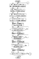
- the predetermined first and second cutting locations of the first and second carrier tapes T1 and T2 are transported and positioned at the first and second cutting positions Lc1 and Lc2 (step S1 in FIG. 22).
- the control device 59 cuts the first and second cutting portions of the first and second carrier tapes T1 and T2 with the first and second cutting devices 54 and 55, and the first and second take-in devices 56 and 57 First and second unnecessary portions are taken in (step S2 in FIG. 22).
- the first tape feeder 50 transports and positions the terminal portion, which is the cut portion of the first carrier tape T1, to the splicing position LS (step S3 in FIG. 22, positioning step).
- the second tape feeder 51 transports and positions the start end portion, which is the cut portion of the second carrier tape T2, to the splicing position LS (step S3 in FIG. 22, positioning step).
- the end portion of the first carrier tape T1 and the start end portion of the second carrier tape T2 are supported on the upper surface of the support plate 97.
- the feed holes Hc1 and Hc2 of the first and second carrier tapes T1 and T2 are positioned at positions where they can be engaged with the first positioning pins 93 and 94 of the joining device 58 provided at the splicing position LS.
- the control device 59 drives the stepping motor 47 of the splicing tape supply member conveying device 36 and pulls out the splicing tape supply member TT wound around the supply reel 33 from the supply reel 33. Then, the back surface splicing tape 30b is once sent to a position detected by the tape detection sensor, and further fed from that position by a certain distance, thereby conveying and positioning a pair of splicing tapes 30 for the front surface and the back surface to the splicing position LS. (Step S4 in FIG. 22).
- the positioning hole 31b formed in the base tape 31 on the surface splicing tape 30a side is engaged with the second positioning pin 105 of the joining device 58 provided at the splicing position LS. Positioned where possible. Further, the positioning hole 30b1 formed in the back surface splicing tape 30b is positioned at a position where it can be engaged with the first positioning pins 93 and 94 of the joining device 58 provided at the splicing position LS.
- the control device 59 When the control device 59 positions the first and second carrier tapes T1 and T2 and the splicing tape 30 at the splicing position LS, the control device 59 excites the stepping motor 47 of the splicing tape supply member transport device 36. That is, the splicing tape 30 is positioned at the splicing position LS to be in a stationary holding state. At this time, since the supply reel holding unit 34 holds the supply reel 33 by applying a frictional force in the direction opposite to the rotation direction, in combination with the splicing tape supply member conveying device 36 in the stationary holding state. The splicing tape 30 can be positioned with high accuracy at the splicing position LS.
- the control device 59 drives the drive motor 120 to rotate the cam drum 110 from the cam phase angle of 0 ° (step S5 in FIG. 22).
- the first elevator 91 is first lifted through the first follower roller 110cc that engages with the first cam groove 110c, and the third follower that engages with the third cam groove 110a.
- the second lifting platform 101 is raised through the roller 110aa.
- the first positioning pins 93 and 94 of the first lifting platform 91 are aligned with the positioning holes 30b1 of the back surface splicing tape 30b and the feed holes Hc of the first and second carrier tapes T1 and T2. Respectively engaged.
- the second positioning pin 105 of the second elevator 101 is engaged with the positioning hole 31b on the surface splicing tape 30a side.
- a support plate 97 is interposed between the back surface splicing tape 30b and the first and second carrier tapes T1 and T2, as shown in FIG.
- the second carrier tapes T1 and T2 do not adhere. Accordingly, the positional relationship between the three of the first and second carrier tapes T1 and T2 and the back surface splicing tape 30b bonded to the back surface of the first and second carrier tapes T1 and T2 is kept constant.
- the movable base 96 is moved in the horizontal direction via the fourth follower roller 110bb engaged with the fourth cam groove 110b, and the second cam groove 110d is moved to the second cam groove 110d.
- the movable base 109 is moved in the horizontal direction via the engaging second follower roller 110dd. Then, by the horizontal movement of the movable table 109, the swivel base 103 is swung clockwise in FIG. 25 via the rack and pinion mechanism (107, 108).
- the support plate 97 interposed between the back surface splicing tape 30b and the first and second carrier tapes T1 and T2 is shown in FIG.
- the back splicing tape 30b and the first and second carrier tapes T1 and T2 can be bonded together.
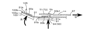
- the base tape 31 engaged with the second positioning pins 105 is bent, and the surface splicing tape 30a is replaced with the first and second carriers.
- the tape is inverted with the adhesive surface facing downward above the tapes T1 and T2. That is, the base tape 31 is bent so as to sandwich the first and second carrier tapes T1 and T2, and the back surface splicing tape 30b is positioned on the back surface side of the first and second carrier tapes T1 and T2, and the first,
- the surface splicing tape 30a is positioned on the surface side of the second carrier tapes T1 and T2.
- the stepping motor 47 of the splicing tape supply member conveying device 36 is rotated in the reverse direction, the base tape 31 is slackened, and the base tape 31 is allowed to be bent.
- the cam phase angle of the cam drum 110 reaches 110 °
- the second elevator 101 reaches the top dead center
- the swivel 103 reaches the turn downward.
- the downward turning of the swivel base 103 is maintained until the cam phase angle of the cam drum 110 reaches 235 °.
- the cam phase angle of the cam drum 110 reaches 30 ° to 110 °
- the first lifting platform 91 is raised.
- the end portions of the first and second carrier tapes T1 and T2 may be bent by the backward movement of the support plate 97 that supports the end portions of the first and second carrier tapes T1 and T2.
- the first pressing member 91a supports the end portions of the first and second carrier tapes T1 and T2, so that the above-described bending can be prevented.
- the second lifting platform 101 When the cam phase angle of the cam drum 110 exceeds 110 °, the second lifting platform 101 starts to descend. At this time, the first lifting platform 91 continues to rise. Thereby, as shown in FIG. 27, the second positioning pins 105 of the second lifting platform 101 are arranged so that the positioning holes 31b of the base tape 31 and the feed holes of the first and second carrier tapes T1 and T2 from the back side of the base tape 31. Hc and the back surface splicing tape 30b are engaged with the positioning holes 30b1.
- the folded base tape 31 is pressed between the swivel base 103 and the first lift base 91 with the first and second carrier tapes T1 and T2 sandwiched therebetween (pressing). Process).
- the back surface splicing tape 30b affixed to the base tape 31 is bonded so as to straddle the back surfaces of the first and second carrier tapes T1 and T2, and the front surface splicing tape 30a is bonded to the first and second carriers.
- Adhering across the cover tapes Tt affixed to the surfaces of the tapes T1 and T2 are connected to each other.
- the first and second carrier tapes T1 and T2 are connected by the splicing tape 30 so that the first and second carrier tapes T1 and T2 and the splicing tape 30 are relatively connected by the first positioning pins 93 and 94 and the second positioning pin 105. Since it is performed in a state where the displacement is restrained, the first and second carrier tapes T1 and T2 can be accurately joined without causing a pitch displacement.
- the pressing state of the swivel base 103 and the first lifting / lowering base 91 is maintained until the cam phase angle of the cam drum 110 reaches 215 °, but the controller 59 determines that the cam phase angle of the cam drum 110 is in the middle of the pressing state. It is determined whether or not 180 ° has been reached, that is, whether or not a detection signal has been received from the splicing sensor 112 (step S6 in FIG. 22). When the detection signal is received from the splicing sensor 112, the drive motor 120 is stopped and the series of cam operations are temporarily stopped (step S7 in FIG. 22, stop process).
- step S8 in FIG. 22 it is determined by the timer measurement built in the control device 59 whether or not the drive stop time of the drive motor 120 has elapsed for a predetermined time (step S8 in FIG. 22), and the drive stop time of the drive motor 120 has elapsed for the predetermined time. If so, the drive of the drive motor 120 is resumed (step S9 in FIG. 22).
- the second lifting platform 101 starts to rise, until the cam phase angle of the cam drum 110 reaches 235 °, that is, the height h before reaching the top dead center (see FIG. 18). ) And the second elevator 101 is raised and stopped. As a result, pressing of the bent base tape 31 is released, and the second positioning pin 105 is detached from the positioning hole 31b on the surface splicing tape 30a side and the feed holes Hc of the first and second carrier tapes T1 and T2. Is done.
- the control device 59 stops driving the drive motor 120 (step S11 in FIG. 22), and drives the motor 352b of the top film transport device 35. Then, after applying tension to the top film 32 and peeling off the top film 32 by a necessary amount, the driving of the motor 352b is stopped. Thus, the joining of the end portion of the first carrier tape T1 and the start end portion of the second carrier tape T2 is completed. Then, it is determined whether or not the next splicing is performed (step S12 in FIG. 22). If the next splicing is performed, the process returns to step S1 and the above processing is repeated. If the next splicing is not performed, all the processing is performed. Exit.
- the series of operations when the first and second carrier tapes T1 and T2 are connected by the splicing tape 30 is the first and second lifting platforms 91,
- 101 moves up and down
- the support plate 97 moves horizontally
- the swivel base 103 turns left and right (the movable base 96 moves horizontally). That is, the pressing surface 91b of the first pressing member 91a and the pressing surface 103b of the second pressing member 103a start moving in the pressing direction from the non-pressing initial position, and shift to the pressing state.
- This is an operation of starting movement in the separation direction and returning to the initial position.
- the driving device is not limited to the cam and the driving motor 120 of the present embodiment.
- Four direct acting actuators for example, air cylinders, hydraulic cylinders, linear motors, etc.
- each member is connected by one link mechanism, and one motor that operates this link mechanism
- one direct acting actuator may be used.
- Each member described above is configured to be operated by one cam drum 110 and four drive motors 120 provided with four cam grooves 110c, 110a, 110d, and 110b.
- One cam drum may be provided, or a plurality of cam drums in which arbitrary combinations of cam grooves are formed, and one or a plurality of drive motors for driving each cam drum may be provided. This configuration is the same in the case of a combination of the above-described link mechanism and a motor or a direct acting actuator.
- a DC motor is used as the drive motor 120
- a stepping motor a servo motor, an AC motor, an ultrasonic motor, an electrostatic force motor, a hydraulic motor, a pneumatic motor, or the like
- a stepping motor it can be controlled by the number of pulses, and an origin sensor 111 and a splicing sensor 112 are provided.
- a servo motor it can be controlled by an encoder and only the splicing sensor 112 is provided.
- the transmission type photoelectric sensor is used as the origin sensor 111 and the splicing sensor 112
- a reflection type photoelectric sensor may be used.
- an electromagnetic sensor, a sound wave sensor, a mechanical contact sensor, or the like can be used.
- the drive stop point is detected by the splicing sensor 112, the drive stop point may be obtained by the elapsed time after the origin is detected by the origin sensor 111.
- the splicing device 20 is a splicing device 20 that connects the first carrier tape T1 and the second carrier tape T2 having the component storage cavity Ct by the first splicing tape 30a and the second splicing tape 30b.
- Positioning device 50 for sending the first carrier tape T1 and the second carrier tape t2 toward each other and positioning the end of the first carrier tape T1 and the end of the second carrier tape T2 at the splicing position LS, 51 and the first splicing tape 30a is pressed against one surface of the first carrier tape T1 and the second carrier tape T2 across the first carrier tape T1 and the second carrier tape T2 positioned at the splicing position LS.
- a pressing member 91a That.
- a second pressing that presses the second splicing tape 30b against the other surface of the first carrier tape T1 and the second carrier tape T2 across the first carrier tape T1 and the second carrier tape T2 positioned at the splicing position LS.
- Drive devices 120, 110, 110a for reciprocally moving the pressing surface 91b of the first pressing member 91a and the pressing surface 101b of the second pressing member 101a relatively close to and away from each other by the member 101a and a series of operations.
- First carrier tape T1 and second carrier Provided in the pressing state is pressed against the tape T2, drive 120,110,110a, 110b, 110c, a control unit 59 to pause the series of operations of 110d or the like, and.
- the splicing device 20 includes the first and second pressing members 91a and 101a. Since a series of operations of the driving devices 120, 110, 110a, 110b, 110c, 110d and the like for driving the pressing members 91a, 101a are temporarily stopped, the pressing time of the splicing tapes 30a, 30b against the first and second carrier tapes T1, T2 Can be lengthened. Therefore, the splicing tapes 30a and 30b can be reliably attached to the first and second carrier tapes T1 and T2.
- the drive device is a cam 110, 110a, 110b that reciprocally moves the pressing surface 91b of the first pressing member 91a and the pressing surface 101b of the second pressing member 101a relatively close to and away from each other by a series of operations. , 110c, 110d, etc., and a cam driving device 120 that drives the cams 110, 110a, 110b, 110c, 110d, etc. and causes the cams 110, 110a, 110b, 110c, 110d, etc. to execute a series of operations. 59 temporarily stops a series of operations of the cams 110, 110a, 110b, 110c, 110d and the like by temporarily stopping the cam driving device 120 in the pressing state.
- the drive device can be configured simply and at low cost.
- the cams 110, 110a, 110b, 110c, 110d and the like perform a series of operations once by rotating once, and the cams 110, 110a, 110b, 110c, 110d and the like are pressed in a predetermined angle range during one rotation.
- the control device 59 temporarily stops a series of operations of the cams 110, 110a, 110b, 110c, 110d, etc. while the cams 110, 110a, 110b, 110c, 110d, etc. are operating within a predetermined angle range in the series of operations. . Since the control device 59 only needs to temporarily stop the cams 110, 110a, 110b, 110c, 110d and the like while operating within a predetermined angle range in a series of operations, the control device 59 can easily perform the pause control.
- control device 59 temporarily stops a series of operations of the cams 110, 110a, 110b, 110c, 110d, etc., when the cams 110, 110a, 110b, 110c, 110d, etc. are located at the center of the predetermined angle range. Even if the timing of temporary stop of the cams 110, 110a, 110b, 110c, 110d, etc. varies, the first and second pressing members 91a, 101a replace the splicing tapes 30a, 30b with the first and second carrier tapes T1, T2. The pressing state pressed against the first and second carrier tapes T1 and T2 can be reliably attached to the first and second carrier tapes T1 and T2.
- the splicing device 20 is configured to connect the splicing tape supply member TT including the first splicing tape 30a and the second splicing tape 30b attached to the base tape 31 and the base tape 31 to the first carrier tape T1 and the second carrier tape T2.
- the driving device includes a transport device 36 that feeds in a direction crossing the feeding direction, and the driving device performs the first pressing in a state where the pressing surface 91b of the first pressing member 91a faces the pressing surface 101b of the second pressing member 101a by a series of operations.
- the position facing the pressing surface 91b of the first pressing member 91a and the base Moves between the position not opposed to the pressing surface 91b of the first pressing member 91a extending the tape 31, comprising a second cam 110d of the cam, and 110Dd, the.
- the second pressing member 101a is moved toward and away from the first pressing member 91a.
- the control device 59 temporarily stops a series of operations of the first cams 110c and 110cc, the second cams 110d and 110dd, and the third cams 110a and 110aa by temporarily stopping the cam driving device 120 in the pressing state. Since the control device 59 only needs to control the cam drive device 120, the series of operations of the cams 110, 110a, 110b, 110c, 110d and the like can be reliably stopped.
- the splicing method of the above-described embodiment is a splicing method in which the first carrier tape T1 and the second carrier tape T2 having the component storage cavity Ct are connected by the first splicing tape 30a and the second splicing tape 30b.
- the first carrier tape straddling the first splicing tape 30a over the first carrier tape T1 and the second carrier tape T2 positioned at the splicing position LS by a series of operations such as 120, 110, 110a, 110b, 110c, and 110d.
- the first carrier tape T1 and the second carrier tape T2 are pressed against one surface of the two carrier tape T2 and the second splicing tape 30b is straddled across the first carrier tape T1 and the second carrier tape T2 positioned at the splicing position LS. And a pressing step of pressing against the other surface.
- SYMBOLS 20 ... Splicing device, 30 (30a, 30b) ... Splicing tape, 36 ... Splicing tape supply member conveying device, 50 ... First tape feeding device (positioning device), 51 ... Second tape feeding device (positioning device), 58 ... Joining device, 91 ... first lifting platform, 91a ... first pressing member, 91b ... pressing surface, 97 ... support plate, 101 ... second lifting platform, 103 ... swivel table, 103a ... second pressing member, 103b ...
Landscapes
- Engineering & Computer Science (AREA)
- Manufacturing & Machinery (AREA)
- Microelectronics & Electronic Packaging (AREA)
- Supply And Installment Of Electrical Components (AREA)
- Replacement Of Web Rolls (AREA)
Abstract
La présente invention concerne un appareil d'épissage (20) qui comprend : un dispositif d'entraînement (120, etc.) qui, en effectuant une série d'opérations, provoque des mouvements alternatifs relatifs d'une surface de pressage (91b) d'un premier élément de pressage (91a) et d'une surface de pressage (101b) d'un deuxième élément de pressage (101a) dans une direction dans laquelle la surface de pressage (91b) et la surface de presage (101b) s'approchent ou sont séparées l'une de l'autre ; et un dispositif de commande (59) qui suspend temporairement la série d'opérations du dispositif d'entraînement (120, etc.) pendant un état de pressage dans lequel, en résultat de la série d'opérations du dispositif d'entraînement (120, etc.), un premier ruban d'épissage (30a) et un deuxième ruban d'épissage (30b) sont respectivement pressés contre un premier ruban support (T1) et un deuxième ruban support (T2) par le premier élément de pressage (91a) et le deuxième élément de pressage (101a).
Priority Applications (5)
| Application Number | Priority Date | Filing Date | Title |
|---|---|---|---|
| CN201680087747.2A CN109565949B (zh) | 2016-07-19 | 2016-07-19 | 拼接装置及拼接方法 |
| EP16909488.5A EP3490360B1 (fr) | 2016-07-19 | 2016-07-19 | Appareil d'épissage et procédé d'épissage |
| PCT/JP2016/071191 WO2018016013A1 (fr) | 2016-07-19 | 2016-07-19 | Appareil d'épissage et procédé d'épissage |
| US16/315,290 US10961072B2 (en) | 2016-07-19 | 2016-07-19 | Splicing device and splicing method |
| JP2018528134A JP6744918B2 (ja) | 2016-07-19 | 2016-07-19 | スプライシング装置及びスプライシング方法 |
Applications Claiming Priority (1)
| Application Number | Priority Date | Filing Date | Title |
|---|---|---|---|
| PCT/JP2016/071191 WO2018016013A1 (fr) | 2016-07-19 | 2016-07-19 | Appareil d'épissage et procédé d'épissage |
Publications (1)
| Publication Number | Publication Date |
|---|---|
| WO2018016013A1 true WO2018016013A1 (fr) | 2018-01-25 |
Family
ID=60993171
Family Applications (1)
| Application Number | Title | Priority Date | Filing Date |
|---|---|---|---|
| PCT/JP2016/071191 Ceased WO2018016013A1 (fr) | 2016-07-19 | 2016-07-19 | Appareil d'épissage et procédé d'épissage |
Country Status (5)
| Country | Link |
|---|---|
| US (1) | US10961072B2 (fr) |
| EP (1) | EP3490360B1 (fr) |
| JP (1) | JP6744918B2 (fr) |
| CN (1) | CN109565949B (fr) |
| WO (1) | WO2018016013A1 (fr) |
Families Citing this family (4)
| Publication number | Priority date | Publication date | Assignee | Title |
|---|---|---|---|---|
| CN114126396A (zh) * | 2020-08-26 | 2022-03-01 | 金东奭 | 连接夹具胶带 |
| CN114734493B (zh) * | 2022-03-23 | 2025-05-16 | 深圳科宏健科技有限公司 | 切料装置及其在接料机上的应用 |
| CN115418848B (zh) * | 2022-09-23 | 2024-02-13 | 绍兴博利豪家纺有限公司 | 一种高效裁布机 |
| CN117719966A (zh) * | 2023-12-15 | 2024-03-19 | 宁波申洲针织有限公司 | 一种全自动绳头连接装置 |
Citations (6)
| Publication number | Priority date | Publication date | Assignee | Title |
|---|---|---|---|---|
| JPS5319811A (en) * | 1976-08-06 | 1978-02-23 | Matsushita Electric Ind Co Ltd | Magnetic tape splicer |
| JPH05338877A (ja) * | 1992-06-09 | 1993-12-21 | Toshiba Mach Co Ltd | 走行カッタ式バットスプライス方法および装置 |
| JP2002207286A (ja) * | 2001-01-09 | 2002-07-26 | Mitsui Mining & Smelting Co Ltd | フィルム接合装置の位置合わせ方法およびそのための位置合わせ用ゲージ部材ならびにフィルム接合装置 |
| WO2013157107A1 (fr) | 2012-04-18 | 2013-10-24 | 富士機械製造株式会社 | Dispositif de raccordement, et procédé de raccordement |
| WO2014167692A1 (fr) * | 2013-04-11 | 2014-10-16 | 富士機械製造株式会社 | Dispositif d'épissurage |
| JP2014225591A (ja) * | 2013-05-17 | 2014-12-04 | パナソニック株式会社 | スプライシング装置 |
Family Cites Families (13)
| Publication number | Priority date | Publication date | Assignee | Title |
|---|---|---|---|---|
| US3995791A (en) * | 1975-07-09 | 1976-12-07 | Package Machinery Company | Continuous web supply system |
| US4815405A (en) * | 1987-10-13 | 1989-03-28 | Young Engineering, Inc, | Apparatus for splicing indeterminate lengths of fabric |
| US5066346A (en) * | 1990-01-26 | 1991-11-19 | Eastman Kodak Company | Apparatus and method for splicing webs of indeterminate length |
| US5066345A (en) * | 1990-01-26 | 1991-11-19 | Eastman Kodak Company | Apparatus and method for splicing webs of indeterminate length |
| US5053096A (en) * | 1990-01-26 | 1991-10-01 | Eastman Kodak Company | Apparatus and method for splicing webs of indeterminate length |
| ES2149657B1 (es) * | 1997-05-05 | 2001-05-16 | Barberan Sa | Cabezal para el cambio automatico de bobinas suministradoras de folio en continuo. |
| JP4255614B2 (ja) * | 2000-12-18 | 2009-04-15 | 三井金属鉱業株式会社 | フィルム接合装置およびフィルム接合方法ならびにそのためのフィルムの切除方法 |
| JP2005307217A (ja) * | 2005-05-11 | 2005-11-04 | Mitsui Chemicals Inc | 基材繋ぎ方法 |
| JP4512019B2 (ja) * | 2005-09-30 | 2010-07-28 | 三菱重工業株式会社 | 紙継ぎ装置 |
| JP5930599B2 (ja) * | 2011-04-05 | 2016-06-08 | 富士機械製造株式会社 | 電子部品装着方法及び装着装置 |
| JP2013065748A (ja) * | 2011-09-20 | 2013-04-11 | Panasonic Corp | 電子部品実装装置およびテープフィーダならびにテープフィーダにおけるトップテープ送り方法 |
| CN104221486B (zh) * | 2012-04-18 | 2016-12-07 | 富士机械制造株式会社 | 自动拼接装置 |
| CN105379446B (zh) * | 2013-07-12 | 2018-09-25 | 富士机械制造株式会社 | 元件组装装置的向基板组装元件的方法及元件组装装置 |
-
2016
- 2016-07-19 JP JP2018528134A patent/JP6744918B2/ja active Active
- 2016-07-19 CN CN201680087747.2A patent/CN109565949B/zh active Active
- 2016-07-19 WO PCT/JP2016/071191 patent/WO2018016013A1/fr not_active Ceased
- 2016-07-19 EP EP16909488.5A patent/EP3490360B1/fr active Active
- 2016-07-19 US US16/315,290 patent/US10961072B2/en active Active
Patent Citations (6)
| Publication number | Priority date | Publication date | Assignee | Title |
|---|---|---|---|---|
| JPS5319811A (en) * | 1976-08-06 | 1978-02-23 | Matsushita Electric Ind Co Ltd | Magnetic tape splicer |
| JPH05338877A (ja) * | 1992-06-09 | 1993-12-21 | Toshiba Mach Co Ltd | 走行カッタ式バットスプライス方法および装置 |
| JP2002207286A (ja) * | 2001-01-09 | 2002-07-26 | Mitsui Mining & Smelting Co Ltd | フィルム接合装置の位置合わせ方法およびそのための位置合わせ用ゲージ部材ならびにフィルム接合装置 |
| WO2013157107A1 (fr) | 2012-04-18 | 2013-10-24 | 富士機械製造株式会社 | Dispositif de raccordement, et procédé de raccordement |
| WO2014167692A1 (fr) * | 2013-04-11 | 2014-10-16 | 富士機械製造株式会社 | Dispositif d'épissurage |
| JP2014225591A (ja) * | 2013-05-17 | 2014-12-04 | パナソニック株式会社 | スプライシング装置 |
Also Published As
| Publication number | Publication date |
|---|---|
| EP3490360A4 (fr) | 2019-08-07 |
| CN109565949B (zh) | 2020-07-14 |
| CN109565949A (zh) | 2019-04-02 |
| EP3490360B1 (fr) | 2021-02-17 |
| JPWO2018016013A1 (ja) | 2019-05-09 |
| JP6744918B2 (ja) | 2020-08-19 |
| US20200180889A1 (en) | 2020-06-11 |
| US10961072B2 (en) | 2021-03-30 |
| EP3490360A1 (fr) | 2019-05-29 |
Similar Documents
| Publication | Publication Date | Title |
|---|---|---|
| JP5897112B2 (ja) | スプライシング装置およびスプライシング方法 | |
| JP6067034B2 (ja) | スプライシングテープ送り装置および送り方法 | |
| WO2018016013A1 (fr) | Appareil d'épissage et procédé d'épissage | |
| KR20130098688A (ko) | 호이스트 장치 및 이를 갖는 호이스트 시스템 | |
| JP5963850B2 (ja) | スプライシングテープ | |
| JP2714344B2 (ja) | テープ巻き取り装置 | |
| JP6247000B2 (ja) | フィルムフィーダおよび組立作業機 | |
| CN114166762A (zh) | 一种pcb板剥膜检测装置 | |
| JP3366745B2 (ja) | ラベル貼付方法 | |
| US11597619B2 (en) | Sheet supply device and sheet supply method | |
| JP3810722B2 (ja) | ラベル貼付装置 | |
| JP2009161207A (ja) | テープ結束装置 | |
| JP6641384B2 (ja) | スプライシング装置 | |
| JP2003226306A (ja) | テーピング装置 | |
| JP6754373B2 (ja) | スプライシング装置 | |
| CN110901121A (zh) | 供料系统及具有其的成型机 | |
| US11286129B2 (en) | Sheet supply device and sheet supply method | |
| JP4423093B2 (ja) | 塗付装置及び集成材製造装置。 | |
| JPH08175506A (ja) | 包装装置 | |
| WO2019146033A1 (fr) | Dispositif d'épissage | |
| JP2022062426A (ja) | シート供給装置およびシート供給方法 | |
| JP2004250169A (ja) | ロール状物の端部処理方法およびその端部処理装置 | |
| CN115057022A (zh) | 一种带旋转提升装置的栈板传输设备 | |
| JP3008053B2 (ja) | 紙テープの端末の処理方法と処理装置 | |
| CN114834677A (zh) | 一种自动化生产线及其翻转装置 |
Legal Events
| Date | Code | Title | Description |
|---|---|---|---|
| ENP | Entry into the national phase |
Ref document number: 2018528134 Country of ref document: JP Kind code of ref document: A |
|
| 121 | Ep: the epo has been informed by wipo that ep was designated in this application |
Ref document number: 16909488 Country of ref document: EP Kind code of ref document: A1 |
|
| NENP | Non-entry into the national phase |
Ref country code: DE |
|
| ENP | Entry into the national phase |
Ref document number: 2016909488 Country of ref document: EP Effective date: 20190219 |