WO2018016136A1 - 電池パック - Google Patents
電池パック Download PDFInfo
- Publication number
- WO2018016136A1 WO2018016136A1 PCT/JP2017/014096 JP2017014096W WO2018016136A1 WO 2018016136 A1 WO2018016136 A1 WO 2018016136A1 JP 2017014096 W JP2017014096 W JP 2017014096W WO 2018016136 A1 WO2018016136 A1 WO 2018016136A1
- Authority
- WO
- WIPO (PCT)
- Prior art keywords
- lid
- housing
- opening
- seal member
- battery pack
- Prior art date
- Legal status (The legal status is an assumption and is not a legal conclusion. Google has not performed a legal analysis and makes no representation as to the accuracy of the status listed.)
- Ceased
Links
Images


Classifications
-
- H—ELECTRICITY
- H01—ELECTRIC ELEMENTS
- H01M—PROCESSES OR MEANS, e.g. BATTERIES, FOR THE DIRECT CONVERSION OF CHEMICAL ENERGY INTO ELECTRICAL ENERGY
- H01M50/00—Constructional details or processes of manufacture of the non-active parts of electrochemical cells other than fuel cells, e.g. hybrid cells
- H01M50/20—Mountings; Secondary casings or frames; Racks, modules or packs; Suspension devices; Shock absorbers; Transport or carrying devices; Holders
- H01M50/204—Racks, modules or packs for multiple batteries or multiple cells
-
- H—ELECTRICITY
- H01—ELECTRIC ELEMENTS
- H01M—PROCESSES OR MEANS, e.g. BATTERIES, FOR THE DIRECT CONVERSION OF CHEMICAL ENERGY INTO ELECTRICAL ENERGY
- H01M50/00—Constructional details or processes of manufacture of the non-active parts of electrochemical cells other than fuel cells, e.g. hybrid cells
- H01M50/20—Mountings; Secondary casings or frames; Racks, modules or packs; Suspension devices; Shock absorbers; Transport or carrying devices; Holders
- H01M50/271—Lids or covers for the racks or secondary casings
- H01M50/273—Lids or covers for the racks or secondary casings characterised by the material
- H01M50/276—Inorganic material
-
- Y—GENERAL TAGGING OF NEW TECHNOLOGICAL DEVELOPMENTS; GENERAL TAGGING OF CROSS-SECTIONAL TECHNOLOGIES SPANNING OVER SEVERAL SECTIONS OF THE IPC; TECHNICAL SUBJECTS COVERED BY FORMER USPC CROSS-REFERENCE ART COLLECTIONS [XRACs] AND DIGESTS
- Y02—TECHNOLOGIES OR APPLICATIONS FOR MITIGATION OR ADAPTATION AGAINST CLIMATE CHANGE
- Y02E—REDUCTION OF GREENHOUSE GAS [GHG] EMISSIONS, RELATED TO ENERGY GENERATION, TRANSMISSION OR DISTRIBUTION
- Y02E60/00—Enabling technologies; Technologies with a potential or indirect contribution to GHG emissions mitigation
- Y02E60/10—Energy storage using batteries
Definitions
- One aspect of the present invention relates to a battery pack.
- Patent Document 1 discloses a battery pack including a plurality of battery cells and a housing that houses the plurality of battery cells.
- the battery pack casing is provided with a pressure release portion composed of an opening and a sealing plate for sealing the opening.
- the pressure release part discharges the gas filled in the casing to the outside through the deformation of the sealing plate as the pressure in the casing increases. Thereby, the pressure release part prevents the pressure in a housing
- a sealing member is used to seal between the sealing plate and the housing when not deformed.
- the sealing member for example, a sealing member that is disposed between the sealing plate and the housing and is fixed to both can be used. In that case, the opening is irreversibly opened when the sealing member is broken according to the deformation of the sealing plate.
- the state of the sealing plate returns to the state before the deformation, a configuration that reversibly opens the opening by using a sealing member that exhibits sealing properties again is desired. ing.
- One aspect of the present invention provides a battery pack capable of suppressing the displacement of the seal member.
- a battery pack includes a battery module, a housing that houses the battery module, a plate-like lid that closes an opening provided in the housing, and a peripheral portion of the opening and the lid. And a seal member that is disposed between and compressed by the peripheral edge of the opening and the lid body and exhibits a sealing property by being elastically deformed.
- the lid has a fixed part fixed to the housing and an extending part extending from the fixed part to the peripheral part.
- the extension portion opens so as to be separated from the peripheral portion with the fixed portion as a starting point in response to an increase in pressure in the housing.
- the seal member is bonded to the housing or the lid.
- the extending portion of the lid body is deformed so as to be separated from the peripheral portion with the fixed portion as a starting point in response to an increase in pressure in the housing, thereby opening the housing opening. That is, the lid functions as a so-called safety valve that prevents the pressure in the housing from rising abnormally.
- the seal member is disposed between the peripheral edge portion of the opening and the lid, and is compressed by these to be elastically deformed to exhibit a sealing property. Therefore, when the lid is deformed, the sealing performance is lowered due to weak compression of the seal member, and the opening is opened. When the lid body returns to the state before deformation, the sealing member can be re-compressed to exhibit the sealing performance again. That is, the opening can be reversibly sealed and released.
- the seal member is bonded to the housing or the lid, the positional deviation of the seal member can be suppressed even when the lid is deformed. As a result, the opening can be reliably resealed when the lid returns to the original state before deformation.
- the battery pack according to one aspect of the present invention may be disposed between the housing and the lid, and may further include a spacer that defines a compression rate of the seal member.
- the compression rate of the seal member can be easily defined. Therefore, the gap between the peripheral edge portion and the lid can be reliably sealed by the seal member.
- the spacer may be disposed between the housing and the fixing portion, or may be fixed to the housing together with the fixing portion. In this case, it is not necessary to attach a spacer to the housing separately.
- the sealing member may be bonded to the peripheral portion.
- the extended portion is deformed so as to be separated from the peripheral portion and the opening is opened, the gas in the housing tends to flow out of the housing along the extending portion. Therefore, in this case, it is difficult for the flowing gas flow to hit the sealing member bonded to the peripheral edge of the casing. Thereby, peeling of a sealing member is suppressed.
- the sealing member may be bonded to the lid body along the periphery of the lid body.
- the lid since the lid is smaller than the casing and easy to handle, the step of bonding the seal member can be easily performed.
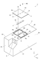
- FIG. 3 is a sectional view taken along line III-III in FIG. 1. It is a graph for demonstrating the sealing performance establishment range of a sealing member.
- FIG. 1 is a perspective view showing the battery pack according to the first embodiment.
- FIG. 2 is an exploded perspective view of the battery pack of FIG. 3 is a cross-sectional view taken along line III-III in FIG.
- the battery pack 1 includes a housing 2, a lid 3, a plurality of battery modules 4, a connector 5, a seal member 6, and a spacer 7. .
- the battery pack 1 is a device used as a battery for vehicles such as electric vehicles and forklifts.
- the battery pack 1 is accommodated in a predetermined battery accommodating part on the vehicle side.
- the housing 2 is a box having a rectangular parallelepiped shape as a whole.
- the housing 2 accommodates a plurality of battery modules 4 in the internal space S of the housing 2.
- the housing 2 includes a bottom wall portion 21, an upper wall portion 22, a first side wall portion 23, a second side wall portion 24, a front wall portion 25, and a rear wall portion 26.
- the bottom wall part 21, the upper wall part 22, the first side wall part 23, the second side wall part 24, the front wall part 25, and the rear wall part 26 are integrated by welding or fastening by bolts (not shown).
- the bottom wall part 21, the upper wall part 22, the first side wall part 23, the second side wall part 24, the front wall part 25, and the rear wall part 26 are formed of a general steel material such as SS400 and SPHC, for example. .
- the bottom wall portion 21 is formed of, for example, a rectangular plate material having a thickness of 50 mm.
- the upper wall portion 22 is formed of, for example, a plate material having a thickness of 10 mm.
- the 1st side wall part 23 and the 2nd side wall part 24 are formed with the board
- the front wall portion 25 and the rear wall portion 26 are formed of, for example, a plate material having a thickness of 5 mm.
- the first side wall part 23, the second side wall part 24, the front wall part 25, and the rear wall part 26 are erected along four sides forming the periphery of the bottom wall part 21.
- the first side wall part 23 and the second side wall part 24 face each other.
- the first side wall part 23 and the second side wall part 24 are provided with a plurality of screw holes H1 for fixing the battery module 4 to the first side wall part 23 and the second side wall part 24 with bolts B1.
- the front wall portion 25 and the rear wall portion 26 face each other.
- the upper wall portion 22 is connected to the ends of the first side wall portion 23, the second side wall portion 24, the front wall portion 25, and the rear wall portion 26 opposite to the bottom wall portion 21. They are facing each other.
- the direction in which the first side wall portion 23 and the second side wall portion 24 face each other is the X direction
- the direction in which the front wall portion 25 and the rear wall portion 26 face each other is the Y direction
- the Z direction will be described below.
- the upper wall portion 22 is provided with openings A1 and A2 at the center in the Y direction.
- the openings A1 and A2 have a rectangular shape with the same shape.
- the openings A1 and A2 are arranged in parallel in the X direction.
- the opening A1 is disposed on the first side wall portion 23 side, and the opening A2 is disposed on the second side wall portion 24 side.
- the upper wall portion 22 has a peripheral edge R that forms the periphery of the openings A1 and A2.
- the peripheral portion R includes peripheral portions R1 to R7.
- the peripheral edge portion R1 is located between the opening A1 and the opening A2, and extends along the Y direction.
- the peripheral portion R1 is provided with a plurality of screw holes H2 for fixing the lid 3 and the spacer 7 to the peripheral portion R1 with bolts B2.
- the plurality of screw holes H2 are arranged in the Y direction.
- the peripheral portion R2 is opposed to the peripheral portion R1 in the X direction across the opening A1, and extends along the Y direction.
- the peripheral portion R3 is opposed to the peripheral portion R1 in the X direction across the opening A2, and extends along the Y direction.
- the length of the peripheral portion R2 in the X direction is equal to the thickness of the first side wall portion 23 in the X direction, and the length of the peripheral portion R3 in the X direction is equal to the thickness of the second side wall portion 24 in the X direction. is there.
- the peripheral portion R4 is located on the front wall 25 side of the opening A1 and extends along the X direction.
- the peripheral edge portion R5 is located on the rear wall portion 26 side of the opening A1, and extends along the X direction.
- the peripheral portion R5 is opposed to the peripheral portion R4 in the Y direction across the opening A1.
- the peripheral edge portion R6 is located on the front wall 25 side of the opening A2, and extends along the X direction.
- the peripheral edge portion R7 is located on the rear wall portion 26 side of the opening A2, and extends along the X direction.
- the peripheral portion R7 faces the peripheral portion R6 in the Y direction across the opening A2.
- the lid 3 is formed of, for example, a general steel material such as SS400 or SPHC.
- the lid 3 is formed of, for example, a rectangular plate material having a thickness of 5 mm.
- the thickness and rigidity of the lid 3 are smaller than the thickness and rigidity of each part of the housing 2.
- the lid 3 is disposed on the upper wall portion 22 and closes the openings A1 and A2.
- the lid 3 has an inner surface 3a, and the inner surface 3a faces the peripheral edge R in the Z direction.
- the shape of the lid 3 is set to a shape that can completely cover the openings A ⁇ b> 1 and A ⁇ b> 2 and can face the peripheral edge R.
- the lid 3 has a fixed portion 31 and extending portions 32 and 33.
- the fixing part 31 is a part fixed to the housing 2.
- the fixing portion 31 extends along the Y direction at the center of the lid 3 in the X direction.
- the fixed portion 31 is provided with a plurality of through holes H3 arranged in the Y direction.
- the plurality of through holes H3 are provided at positions overlapping the plurality of screw holes H2 when viewed from the Z direction.
- the fixing portion 31 faces the peripheral portion R1 through the spacer 7, and is fixed to the peripheral portion R1 through the spacer 7 by a bolt B2. That is, the peripheral portion R1 functions as a fixed portion to which the lid 3 and the spacer 7 are fixed.
- the bolt B2 is inserted through the through hole H3 and a through hole H4 described later, and is fastened to the screw hole H2.
- the extended portion 32 is a portion that extends from the fixed portion 31 to the peripheral portions R2, R4, and R5 of the peripheral portion R and closes the opening A1.
- the extending part 32 is not fixed to the housing 2.
- the extending portion 32 is deformed (for example, elastically deformed (hereinafter the same)) so as to be separated from the peripheral portions R2, R4, and R5 with the fixing portion 31 as a starting point in response to an increase in pressure in the housing 2. .
- the extension part 32 opens opening A1. Opening the opening A1 means communicating the internal space S and the outside of the housing 2 through the opening A1.
- the extending portion 33 is a portion that extends from the fixing portion 31 to the peripheral portions R3, R6, and R7 of the peripheral portion R and closes the opening A2.
- the extending part 33 is not fixed to the housing 2. For this reason, the extending portion 33 is deformed so as to be separated from the peripheral portions R3, R6, and R7 with the fixing portion 31 as a starting point in accordance with an increase in pressure in the housing 2. Thereby, the extending part 33 opens the opening A2. Opening the opening A2 means communicating the internal space S and the outside of the housing 2 through the opening A2.
- the lid 3 prevents the pressure in the housing 2 from exceeding the specified pressure by opening the openings A1 and A2 by the deformation of the extending portions 32 and 33.
- the lid 3 functions as a so-called safety valve. This specified pressure is set lower than the pressure at which the casing 2 is damaged when the pressure in the casing 2 increases.
- the lid 3 is formed of a thin plate having lower rigidity than the other parts of the housing 2 as described above in order to ensure the ease of deformation of the extending portions 32 and 33.
- the battery module 4 has a plurality of battery cells (not shown), a pair of end plates 11, and a pair of brackets 12.
- the battery cell is a storage battery such as a non-aqueous electrolyte secondary battery such as a lithium ion secondary battery, or an electric double layer capacitor.
- the plurality of battery cells are electrically connected to each other and arranged in the Y direction.
- the pair of end plates 11 are arranged on both sides in the Y direction of the plurality of battery cells arranged in this way. The pair of end plates 11 fixes and integrates a plurality of battery cells.
- the bracket 12 is a member for fixing and attaching a plurality of battery cells to the housing 2.
- the bracket 12 is attached to the end plate 11 on both sides in the Y direction of the plurality of battery cells.
- the bracket 12 is attached to the end plate 11 with a bolt (not shown), for example.
- the bracket 12 is provided with a plurality of through holes H ⁇ b> 5 for fixing the battery module 4 to the first side wall part 23 and the second side wall part 24.
- the through hole H5 overlaps the screw hole H1 when viewed from the X direction.
- the battery module 4 is fixed to the first side wall part 23 and the second side wall part 24 by a bolt B1 inserted through the through hole H5 and fastened to the screw hole H1.
- the connector 5 is a part for connecting the battery pack 1 and an external device.
- the connector 5 is disposed, for example, on the upper wall portion 22 side and the second side wall portion 24 side of the front wall portion 25.
- the seal member 6 is disposed between the peripheral edge R and the lid 3. Specifically, the seal member 6 is disposed between the peripheral edge portions R 2 to R 7 and the inner surface 3 a of the lid 3.
- the seal member 6 has, for example, a long shape, and is arranged in a rectangular ring shape so as to surround the openings A1 and A2 together with the peripheral edge portion R1.
- the seal member 6 includes a seal layer 61 and an adhesive layer 62 provided on one side of the seal layer 61. The seal member 6 is adhered to the peripheral portions R2 to R7 by the adhesive layer 62 with the seal layer 61 facing the lid 3 and the adhesive layer 62 facing the peripheral portions R2 to R7.
- the seal member 6 is bonded only to the casing 2 of the casing 2 and the lid 3.
- the seal layer 61 is made of an elastic member.
- the sealing layer 61 for example, polyurethane sponge, EPDM (ethylene / propylene / diene rubber) sponge or the like can be used.
- the adhesive layer 62 for example, a double-sided tape can be used.
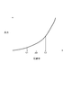
- FIG. 4 is a graph for explaining a range in which the sealing performance of the sealing member is established (sealing performance establishment range).
- the horizontal axis indicates the compression rate of the seal member 6, and the vertical axis indicates the reaction force of the seal member 6. As shown in FIG. 4, the reaction force of the seal member 6 increases as the compression rate increases.
- the compression rate of the seal member 6 exceeds the first predetermined value C1
- the elastic deformation of the seal member 6 becomes sufficiently large.
- the seal member 6 is sufficiently adhered to the member to be sealed (the housing 2 and the lid 3), and sealability is generated.
- the compression rate of the seal member 6 is further increased and exceeds the second predetermined value C2
- the sealing performance is lost due to, for example, the seal member 6 being broken. That is, the sealing performance of the seal member 6 is established in a predetermined compression rate range AR. That is, the seal member 6 exhibits a sealing property in a predetermined pressure range.
- the material for the seal member 6 is selected in consideration of the above properties.
- the sealing property means a property of sealing a member to be sealed in an airtight manner.
- the spacer 7 is a plate-like member formed of a general steel material such as SS400 and SPHC.
- the spacer 7 is disposed between the housing 2 and the lid 3. Specifically, the spacer 7 is disposed between the peripheral edge portion R ⁇ b> 1 and the fixed portion 31.
- the spacer 7 defines the distance between the peripheral portion R ⁇ b> 1 and the fixed portion 31 depending on the thickness of the spacer 7.
- the spacer 7 defines the compression rate of the seal member 6 according to the thickness of the spacer 7.
- the thickness of the spacer 7 is set so that the compression rate of the seal member 6 falls within the sealability establishment range.
- the spacer 7 is formed, for example, corresponding to the shape of the peripheral portion R1.
- the length of the spacer 7 in the X direction is equal to the length of the peripheral portion R1 in the X direction
- the length of the spacer 7 in the Y direction is larger than the length of the peripheral portion R1 in the Y direction. It is formed to be shorter.
- the spacer 7 is disposed, for example, corresponding to the position of the peripheral portion R1. That is, both ends of the spacer 7 in the X direction coincide with both ends of the peripheral portion R1 in the X direction, and both ends of the spacer 7 in the Y direction are screw holes H2 more than both ends of the peripheral portion R1 in the Y direction. It is arranged to be located on the side.
- the spacer 7 is provided with a plurality of through holes H4 aligned in the Y direction.
- the plurality of through holes H4 are provided at positions overlapping the plurality of screw holes H2 when viewed from the Z direction.
- the spacer 7 is fixed to the peripheral portion R1 together with the fixing portion 31 by a bolt B2 that is inserted through the through hole H4.
- the extending portion 32 of the lid 3 is separated from the peripheral portions R ⁇ b> 2, R ⁇ b> 4, and R ⁇ b> 5 with the fixing portion 31 as a starting point in response to an increase in pressure in the housing 2. Transforms into Thereby, the extending part 32 opens the opening A1 of the housing 2.
- the extending portion 33 is deformed so as to be separated from the peripheral portions R3, R6, and R7 with the fixing portion 31 as a starting point in response to an increase in pressure in the housing 2. Thereby, the extending part 33 opens the opening A2 of the housing 2.
- the seal member 6 is disposed between the peripheral portions R2 to R7 of the openings A1 and A2 and the lid 3, and is compressed by these. Thereby, the sealing member 6 is elastically deformed and exhibits sealing properties.
- the seal member 6 has an adhesive layer 62 and is adhered to the peripheral portions R2 to R7 by the adhesive layer 62. Therefore, even when the lid 3 is deformed, the positional deviation of the seal member 6 can be suppressed. As a result, the opening can be reliably resealed when the lid 3 returns to the original state before deformation.
- the battery pack 1 is further provided with a spacer 7 that is disposed between the housing 2 and the lid 3 and that defines the compression rate of the seal member 6. For this reason, the compression rate of the sealing member 6 can be easily defined and the sealing performance can be established. Accordingly, the seal member 6 can reliably seal between the peripheral portions R2 to R7 and the lid 3.
- the spacer 7 is disposed between the peripheral portion R ⁇ b> 1 and the fixed portion 31, and is fixed to the peripheral portion R ⁇ b> 1 together with the fixed portion 31. Thereby, it is not necessary to attach the spacer 7 to the housing
- the spacer 7 is configured as a separate body from the housing 2 and the lid body 3, processing such as thickness adjustment is easier than when the spacer 7 is provided integrally with the housing 2 and the lid body 3. It is. For this reason, the compression rate adjustment of the seal member 6 can be facilitated.
- the gas in the housing 2 flows along the extending portions 32 and 33 in the housing 2. Try to leak outside.
- the seal member 6 is bonded to the peripheral portions R2 to R7. For this reason, it is difficult for the flowing gas flow to hit the seal member 6. Thereby, peeling of the sealing member 6 is suppressed.
- One aspect of the present invention is not limited to the above-described embodiment, but may be modified within the scope not changing the gist described in each claim, or applied to other aspects.
- the seal member 6 may be bonded to the lid 3. That is, the seal member 6 may be bonded only to the lid 3 of the housing 2 and the lid 3.
- the seal member 6 can be configured to adhere to the inner surface 3a in a rectangular ring shape along the periphery of the inner surface 3a so as to face the peripheral portions R2 to R7.
- the lid 3 is smaller than the housing 2 and easy to handle. For this reason, by setting it as the structure which the sealing member 6 adhere
- the sealing member 6 is not limited to the configuration having the sealing layer 61 and the adhesive layer 62, and may itself be configured by an elastic body having adhesiveness.
- a sealing member 6 for example, an ultraviolet curable resin that is cured by irradiation with ultraviolet rays can be used.
- urethane acrylate resin, epoxy acrylate resin, silicone acrylate resin, acrylic resin acrylate, or the like can be used.
- a method for forming the sealing member 6 made of an ultraviolet curable resin on the peripheral portions R2 to R7 will be described below.
- a UV curable resin in a viscous state is applied onto the peripheral portions R2 to R7 with a dispenser.
- the ultraviolet curable resin is irradiated with ultraviolet rays to cure the surface portion of the ultraviolet curable resin.
- the ultraviolet rays to be irradiated are set to a short wavelength (for example, 365 nm). Therefore, it is difficult for ultraviolet rays to reach deep inside the ultraviolet curable resin. As a result, the inside of the ultraviolet curable resin remains in a viscous state.
- a plate member having optical transparency is disposed on the ultraviolet curable resin, and the ultraviolet curable resin is pressed by the plate member. Thereby, the height of the ultraviolet curable resin is made uniform.
- the ultraviolet curable resin is irradiated with ultraviolet rays through the plate member.
- the ultraviolet rays to be irradiated have a long wavelength (for example, 396 nm). Therefore, the ultraviolet rays easily reach deep inside the ultraviolet curable resin. As a result, the ultraviolet curable resin is cured.
- the seal member 6 bonded to the peripheral portions R2 to R7 can be formed. Such a seal member 6 may be formed on the inner surface 3a of the lid 3 instead of being formed on the peripheral portions R2 to R7.
- the spacer 7 may be fixed to the housing 2 separately from the fixing portion 31.
- the spacer 7 may be, for example, a convex portion provided integrally with the housing 2 or the lid 3.
- the shape of the convex portion is not particularly limited, and may be a columnar shape, a hemispherical shape, or the like.
- the battery pack 1 only needs to have at least one opening A1, A2.
- the battery pack 1 only needs to include at least one extending portion 32, 33.
Landscapes
- Chemical & Material Sciences (AREA)
- Chemical Kinetics & Catalysis (AREA)
- Electrochemistry (AREA)
- General Chemical & Material Sciences (AREA)
- Battery Mounting, Suspending (AREA)
- Gas Exhaust Devices For Batteries (AREA)
Applications Claiming Priority (2)
| Application Number | Priority Date | Filing Date | Title |
|---|---|---|---|
| JP2016-142687 | 2016-07-20 | ||
| JP2016142687A JP6690451B2 (ja) | 2016-07-20 | 2016-07-20 | 電池パック |
Publications (1)
| Publication Number | Publication Date |
|---|---|
| WO2018016136A1 true WO2018016136A1 (ja) | 2018-01-25 |
Family
ID=60992031
Family Applications (1)
| Application Number | Title | Priority Date | Filing Date |
|---|---|---|---|
| PCT/JP2017/014096 Ceased WO2018016136A1 (ja) | 2016-07-20 | 2017-04-04 | 電池パック |
Country Status (2)
| Country | Link |
|---|---|
| JP (1) | JP6690451B2 (2) |
| WO (1) | WO2018016136A1 (2) |
Cited By (1)
| Publication number | Priority date | Publication date | Assignee | Title |
|---|---|---|---|---|
| DE102024132950A1 (de) * | 2024-07-11 | 2026-01-15 | Dr. Ing. H.C. F. Porsche Aktiengesellschaft | Batteriezellenmodul |
Families Citing this family (3)
| Publication number | Priority date | Publication date | Assignee | Title |
|---|---|---|---|---|
| KR20240028024A (ko) * | 2022-08-24 | 2024-03-05 | 주식회사 엘지에너지솔루션 | 배터리 모듈 |
| KR20240039485A (ko) * | 2022-09-19 | 2024-03-26 | 주식회사 엘지에너지솔루션 | 배터리 팩 및 이를 포함하는 전력 저장 장치 |
| JP7845168B2 (ja) * | 2022-12-16 | 2026-04-14 | 三菱自動車工業株式会社 | 電池パック |
Citations (4)
| Publication number | Priority date | Publication date | Assignee | Title |
|---|---|---|---|---|
| JP2015125939A (ja) * | 2013-12-26 | 2015-07-06 | 株式会社豊田自動織機 | 電池パック |
| JP2015156302A (ja) * | 2014-02-20 | 2015-08-27 | 株式会社豊田自動織機 | 電池パック |
| JP2015213040A (ja) * | 2014-05-07 | 2015-11-26 | 株式会社豊田自動織機 | 電池収容ケース |
| JP2016066456A (ja) * | 2014-09-24 | 2016-04-28 | 株式会社豊田自動織機 | 電池パック及び産業車両 |
Family Cites Families (2)
| Publication number | Priority date | Publication date | Assignee | Title |
|---|---|---|---|---|
| JP5440790B2 (ja) * | 2010-03-18 | 2014-03-12 | 三菱自動車工業株式会社 | バッテリケース及び電池パック |
| JP2014107178A (ja) * | 2012-11-29 | 2014-06-09 | Mitsubishi Motors Corp | 車両用電池パック |
-
2016
- 2016-07-20 JP JP2016142687A patent/JP6690451B2/ja active Active
-
2017
- 2017-04-04 WO PCT/JP2017/014096 patent/WO2018016136A1/ja not_active Ceased
Patent Citations (4)
| Publication number | Priority date | Publication date | Assignee | Title |
|---|---|---|---|---|
| JP2015125939A (ja) * | 2013-12-26 | 2015-07-06 | 株式会社豊田自動織機 | 電池パック |
| JP2015156302A (ja) * | 2014-02-20 | 2015-08-27 | 株式会社豊田自動織機 | 電池パック |
| JP2015213040A (ja) * | 2014-05-07 | 2015-11-26 | 株式会社豊田自動織機 | 電池収容ケース |
| JP2016066456A (ja) * | 2014-09-24 | 2016-04-28 | 株式会社豊田自動織機 | 電池パック及び産業車両 |
Cited By (1)
| Publication number | Priority date | Publication date | Assignee | Title |
|---|---|---|---|---|
| DE102024132950A1 (de) * | 2024-07-11 | 2026-01-15 | Dr. Ing. H.C. F. Porsche Aktiengesellschaft | Batteriezellenmodul |
Also Published As
| Publication number | Publication date |
|---|---|
| JP2018014223A (ja) | 2018-01-25 |
| JP6690451B2 (ja) | 2020-04-28 |
Similar Documents
| Publication | Publication Date | Title |
|---|---|---|
| WO2018016136A1 (ja) | 電池パック | |
| CN101911337B (zh) | 电池 | |
| CN105977416B (zh) | 电池模块 | |
| JP6474836B2 (ja) | 電池モジュール及びそれを含む電池パック | |
| JP5880109B2 (ja) | バッテリパックの防爆弁 | |
| KR101954043B1 (ko) | 배터리 팩의 압력 개방 기구 | |
| CN100544072C (zh) | 具有非常小的厚度的电池组 | |
| US9159966B2 (en) | Battery case | |
| EP3588663B1 (en) | Battery module case and battery module including same | |
| CN107851746B (zh) | 用于二次电池的盖组件 | |
| JP6094740B2 (ja) | 電装ケース | |
| KR20200030967A (ko) | 절연 구조가 향상된 배터리 모듈 및 이를 포함하는 배터리 팩 | |
| CN106030852B (zh) | 电池组 | |
| JP5355523B2 (ja) | 二次電池及びその製造方法、二次電池に適用されるキャッププレート及びその製造方法、及び密封ユニット | |
| WO2005106988A1 (ja) | ラミネート型二次電池、およびその組電池 | |
| JP5542622B2 (ja) | 電気二重層キャパシタ | |
| JP6724497B2 (ja) | 電池パック | |
| JP2008310966A (ja) | パック電池 | |
| KR20150045242A (ko) | 이차전지용 안전성 실험 시스템 및 이에 적용되는 이차전지용 지그 | |
| WO2019189162A1 (ja) | 蓄電モジュール | |
| WO2019148627A1 (zh) | 电池模组 | |
| CN101855686B (zh) | 用于电化学元件的保护器 | |
| JP7047706B2 (ja) | 燃料電池のスタックケースおよび外部拘束部材 | |
| JP6607020B2 (ja) | 電池パック及び電池パックの製造方法 | |
| CN112768817A (zh) | 电池密封组件、电池模块和汽车 |
Legal Events
| Date | Code | Title | Description |
|---|---|---|---|
| 121 | Ep: the epo has been informed by wipo that ep was designated in this application |
Ref document number: 17830656 Country of ref document: EP Kind code of ref document: A1 |
|
| NENP | Non-entry into the national phase |
Ref country code: DE |
|
| 122 | Ep: pct application non-entry in european phase |
Ref document number: 17830656 Country of ref document: EP Kind code of ref document: A1 |