WO2018016180A1 - レーダ装置、信号処理装置、信号処理方法及び移動体 - Google Patents
レーダ装置、信号処理装置、信号処理方法及び移動体 Download PDFInfo
- Publication number
- WO2018016180A1 WO2018016180A1 PCT/JP2017/019628 JP2017019628W WO2018016180A1 WO 2018016180 A1 WO2018016180 A1 WO 2018016180A1 JP 2017019628 W JP2017019628 W JP 2017019628W WO 2018016180 A1 WO2018016180 A1 WO 2018016180A1
- Authority
- WO
- WIPO (PCT)
- Prior art keywords
- signal
- transmission
- local
- mixer
- shifter
- Prior art date
- Legal status (The legal status is an assumption and is not a legal conclusion. Google has not performed a legal analysis and makes no representation as to the accuracy of the status listed.)
- Ceased
Links
Images


Classifications
-
- G—PHYSICS
- G01—MEASURING; TESTING
- G01S—RADIO DIRECTION-FINDING; RADIO NAVIGATION; DETERMINING DISTANCE OR VELOCITY BY USE OF RADIO WAVES; LOCATING OR PRESENCE-DETECTING BY USE OF THE REFLECTION OR RERADIATION OF RADIO WAVES; ANALOGOUS ARRANGEMENTS USING OTHER WAVES
- G01S7/00—Details of systems according to groups G01S13/00, G01S15/00, G01S17/00
- G01S7/02—Details of systems according to groups G01S13/00, G01S15/00, G01S17/00 of systems according to group G01S13/00
- G01S7/35—Details of non-pulse systems
-
- G—PHYSICS
- G01—MEASURING; TESTING
- G01S—RADIO DIRECTION-FINDING; RADIO NAVIGATION; DETERMINING DISTANCE OR VELOCITY BY USE OF RADIO WAVES; LOCATING OR PRESENCE-DETECTING BY USE OF THE REFLECTION OR RERADIATION OF RADIO WAVES; ANALOGOUS ARRANGEMENTS USING OTHER WAVES
- G01S13/00—Systems using the reflection or reradiation of radio waves, e.g. radar systems; Analogous systems using reflection or reradiation of waves whose nature or wavelength is irrelevant or unspecified
- G01S13/02—Systems using reflection of radio waves, e.g. primary radar systems; Analogous systems
- G01S13/06—Systems determining position data of a target
- G01S13/08—Systems for measuring distance only
- G01S13/32—Systems for measuring distance only using transmission of continuous waves, whether amplitude-, frequency-, or phase-modulated, or unmodulated
- G01S13/34—Systems for measuring distance only using transmission of continuous waves, whether amplitude-, frequency-, or phase-modulated, or unmodulated using transmission of continuous, frequency-modulated waves while heterodyning the received signal, or a signal derived therefrom, with a locally-generated signal related to the contemporaneously transmitted signal
-
- G—PHYSICS
- G01—MEASURING; TESTING
- G01S—RADIO DIRECTION-FINDING; RADIO NAVIGATION; DETERMINING DISTANCE OR VELOCITY BY USE OF RADIO WAVES; LOCATING OR PRESENCE-DETECTING BY USE OF THE REFLECTION OR RERADIATION OF RADIO WAVES; ANALOGOUS ARRANGEMENTS USING OTHER WAVES
- G01S13/00—Systems using the reflection or reradiation of radio waves, e.g. radar systems; Analogous systems using reflection or reradiation of waves whose nature or wavelength is irrelevant or unspecified
- G01S13/02—Systems using reflection of radio waves, e.g. primary radar systems; Analogous systems
- G01S13/06—Systems determining position data of a target
- G01S13/08—Systems for measuring distance only
- G01S13/32—Systems for measuring distance only using transmission of continuous waves, whether amplitude-, frequency-, or phase-modulated, or unmodulated
- G01S13/34—Systems for measuring distance only using transmission of continuous waves, whether amplitude-, frequency-, or phase-modulated, or unmodulated using transmission of continuous, frequency-modulated waves while heterodyning the received signal, or a signal derived therefrom, with a locally-generated signal related to the contemporaneously transmitted signal
- G01S13/343—Systems for measuring distance only using transmission of continuous waves, whether amplitude-, frequency-, or phase-modulated, or unmodulated using transmission of continuous, frequency-modulated waves while heterodyning the received signal, or a signal derived therefrom, with a locally-generated signal related to the contemporaneously transmitted signal using sawtooth modulation
-
- G—PHYSICS
- G01—MEASURING; TESTING
- G01S—RADIO DIRECTION-FINDING; RADIO NAVIGATION; DETERMINING DISTANCE OR VELOCITY BY USE OF RADIO WAVES; LOCATING OR PRESENCE-DETECTING BY USE OF THE REFLECTION OR RERADIATION OF RADIO WAVES; ANALOGOUS ARRANGEMENTS USING OTHER WAVES
- G01S13/00—Systems using the reflection or reradiation of radio waves, e.g. radar systems; Analogous systems using reflection or reradiation of waves whose nature or wavelength is irrelevant or unspecified
- G01S13/88—Radar or analogous systems specially adapted for specific applications
- G01S13/93—Radar or analogous systems specially adapted for specific applications for anti-collision purposes
- G01S13/931—Radar or analogous systems specially adapted for specific applications for anti-collision purposes of land vehicles
-
- G—PHYSICS
- G01—MEASURING; TESTING
- G01S—RADIO DIRECTION-FINDING; RADIO NAVIGATION; DETERMINING DISTANCE OR VELOCITY BY USE OF RADIO WAVES; LOCATING OR PRESENCE-DETECTING BY USE OF THE REFLECTION OR RERADIATION OF RADIO WAVES; ANALOGOUS ARRANGEMENTS USING OTHER WAVES
- G01S7/00—Details of systems according to groups G01S13/00, G01S15/00, G01S17/00
- G01S7/02—Details of systems according to groups G01S13/00, G01S15/00, G01S17/00 of systems according to group G01S13/00
- G01S7/03—Details of HF subsystems specially adapted therefor, e.g. common to transmitter and receiver
- G01S7/038—Feedthrough nulling circuits
-
- G—PHYSICS
- G01—MEASURING; TESTING
- G01S—RADIO DIRECTION-FINDING; RADIO NAVIGATION; DETERMINING DISTANCE OR VELOCITY BY USE OF RADIO WAVES; LOCATING OR PRESENCE-DETECTING BY USE OF THE REFLECTION OR RERADIATION OF RADIO WAVES; ANALOGOUS ARRANGEMENTS USING OTHER WAVES
- G01S7/00—Details of systems according to groups G01S13/00, G01S15/00, G01S17/00
- G01S7/02—Details of systems according to groups G01S13/00, G01S15/00, G01S17/00 of systems according to group G01S13/00
- G01S7/35—Details of non-pulse systems
- G01S7/352—Receivers
- G01S7/354—Extracting wanted echo-signals
-
- G—PHYSICS
- G01—MEASURING; TESTING
- G01S—RADIO DIRECTION-FINDING; RADIO NAVIGATION; DETERMINING DISTANCE OR VELOCITY BY USE OF RADIO WAVES; LOCATING OR PRESENCE-DETECTING BY USE OF THE REFLECTION OR RERADIATION OF RADIO WAVES; ANALOGOUS ARRANGEMENTS USING OTHER WAVES
- G01S13/00—Systems using the reflection or reradiation of radio waves, e.g. radar systems; Analogous systems using reflection or reradiation of waves whose nature or wavelength is irrelevant or unspecified
- G01S13/87—Combinations of radar systems, e.g. primary radar and secondary radar
-
- G—PHYSICS
- G01—MEASURING; TESTING
- G01S—RADIO DIRECTION-FINDING; RADIO NAVIGATION; DETERMINING DISTANCE OR VELOCITY BY USE OF RADIO WAVES; LOCATING OR PRESENCE-DETECTING BY USE OF THE REFLECTION OR RERADIATION OF RADIO WAVES; ANALOGOUS ARRANGEMENTS USING OTHER WAVES
- G01S13/00—Systems using the reflection or reradiation of radio waves, e.g. radar systems; Analogous systems using reflection or reradiation of waves whose nature or wavelength is irrelevant or unspecified
- G01S13/88—Radar or analogous systems specially adapted for specific applications
- G01S13/93—Radar or analogous systems specially adapted for specific applications for anti-collision purposes
- G01S13/931—Radar or analogous systems specially adapted for specific applications for anti-collision purposes of land vehicles
- G01S2013/9327—Sensor installation details
- G01S2013/93271—Sensor installation details in the front of the vehicles
-
- G—PHYSICS
- G01—MEASURING; TESTING
- G01S—RADIO DIRECTION-FINDING; RADIO NAVIGATION; DETERMINING DISTANCE OR VELOCITY BY USE OF RADIO WAVES; LOCATING OR PRESENCE-DETECTING BY USE OF THE REFLECTION OR RERADIATION OF RADIO WAVES; ANALOGOUS ARRANGEMENTS USING OTHER WAVES
- G01S13/00—Systems using the reflection or reradiation of radio waves, e.g. radar systems; Analogous systems using reflection or reradiation of waves whose nature or wavelength is irrelevant or unspecified
- G01S13/88—Radar or analogous systems specially adapted for specific applications
- G01S13/93—Radar or analogous systems specially adapted for specific applications for anti-collision purposes
- G01S13/931—Radar or analogous systems specially adapted for specific applications for anti-collision purposes of land vehicles
- G01S2013/9327—Sensor installation details
- G01S2013/93272—Sensor installation details in the back of the vehicles
Definitions
- the present disclosure relates to a radar device, a signal processing device, a signal processing method, and a moving object.
- FMCW (Frequency Modulated Continuous Waves) radar apparatus may be used as an on-vehicle radar apparatus.
- the ranging method of the FMCW radar apparatus is as follows. A chirp signal whose frequency is linearly increased or decreased with time is emitted from the transmitting antenna as a transmission signal, and the echo signal reflected by the target is captured by the receiving antenna and chirped at the same frequency as the transmission signal. And the echo signal are multiplied by a mixer to receive direct conversion. At the time of this direct conversion reception, the frequency of the local signal changes during the round-trip time until the transmitted signal is reflected back by the target and beats at a frequency proportional to the distance to the target. Take advantage of signal generation.
- the present disclosure proposes a new and improved radar apparatus, signal processing apparatus, signal processing method, and moving body that can exclude the influence based on local feedthrough in the FMCW radar apparatus.
- an oscillator that oscillates a local signal, a transmission antenna that radiates a transmission signal based on the local signal, a reception antenna that receives a reflected wave due to reflection of a target of the transmission signal, and the reflected wave
- a radar apparatus comprising: a mixer that multiplies the local signal with the local signal to generate a multiplication signal; and a first shifter that is provided between the oscillator and the mixer and shifts the phase of the local signal. Is done.
- an oscillator that oscillates a local signal, a reflected wave caused by reflection of a transmission signal based on the local signal, and a mixer that multiplies the local signal to generate a multiplication signal;
- a signal processing device including a shifter provided between an oscillator and the mixer for shifting the phase of the local signal.
- a local signal is oscillated by an oscillator, a transmission signal based on the local signal is radiated from a transmission antenna, and a reflected wave due to reflection of the transmission signal by a target is received by a reception antenna. And generating a multiplication signal by multiplying the reflected wave and the local signal by a mixer, and shifting the phase of the local signal to a shifter provided between the oscillator and the mixer.
- a signal processing method is provided.
- a moving body including the radar device is provided.
- a new and improved radar apparatus, signal processing apparatus, signal processing method, and moving body capable of eliminating the influence based on local feedthrough in the FMCW radar apparatus. I can do it.
- Embodiment of the present disclosure [1.1. Overview] Before describing the embodiment of the present disclosure in detail, first, an outline of the embodiment of the present disclosure will be described.
- an FMCW radar device may be used as an on-vehicle radar device.
- the ranging method of the FMCW radar apparatus is as follows. A chirp signal whose frequency is linearly increased or decreased with time is emitted from the transmitting antenna as a transmission signal, and the echo signal reflected by the target is captured by the receiving antenna and chirped at the same frequency as the transmission signal. And the echo signal are multiplied by a mixer to receive direct conversion. At the time of this direct conversion reception, the frequency of the local signal changes during the round-trip time until the transmitted signal is reflected back by the target and beats at a frequency proportional to the distance to the target. Take advantage of signal generation.
- FIG. 1 is an explanatory diagram showing a configuration example of an FMCW radar apparatus.
- the local oscillator outputs a local signal based on the chirp control signal sent from the FMCW radar signal processing apparatus.
- the local signal output from the local oscillator is amplified as a transmission signal from the transmission antenna after being amplified by the power amplifier.
- the transmission signal is reflected by the target.
- the receiving antenna receives an echo signal that is reflected by the target and returns.
- the echo signal received by the receiving antenna is multiplied by a local signal and a mixer to become a beat signal.
- the beat signal is sent to the FMCW radar signal processing device and used for distance measurement to the target.
- FIG. 2 is an explanatory diagram showing examples of the frequency of the transmission signal, the frequency of the echo signal, and the frequency of the beat signal that change with time.
- the frequency of the transmission signal increases linearly with time from f 0 to f 0 + BW.
- Echo signal the transmission signal is delayed by the round-trip time ⁇ until reflected back by a target, it increases linearly with time from f 0 to f 0 + BW.
- the frequency f B of the beat signal is proportional to the round trip time ⁇ until the transmission signal is reflected by the target and returned. Therefore FMCW radar device, knowing the frequency f B of the beat signal, it is possible to know the distance to the target.
- both the transmission signal emitted from the transmission antenna and the local feedthrough leaking from the reception antenna are chirp signals. Therefore, it cannot be removed by an AC couple or a high-pass filter.
- FIG. 3 is an explanatory diagram showing the influence of local feedthrough in the FMCW radar apparatus.
- the transmission signal emitted from the transmission antenna is reflected by the target and becomes an echo signal 1.
- the local feedthrough leaking from the receiving antenna is reflected by the target and becomes an echo signal 2.
- Each echo signal received by the receiving antenna is multiplied by a local signal and a mixer to become beat signals 1 and 2.
- the two beat signals cannot be separated because they have the same frequency, and the beat signal 2 caused by local feedthrough cannot be removed by an AC couple or a high-pass filter.
- the present disclosure has intensively studied a technique that can eliminate the influence based on local feedthrough in the FMCW radar apparatus.
- the present disclosure has devised a technique capable of excluding the influence based on the local feedthrough in the FMCW radar apparatus by using the phase shifter as described below.
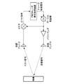
- FIG. 4 is an explanatory diagram illustrating a first configuration example of the FMCW radar apparatus according to the embodiment of the present disclosure.
- a first configuration example of the FMCW radar apparatus will be described with reference to FIG.
- the FMCW radar apparatus 100 includes an FMCW radar signal processing apparatus 110, a signal processing unit 120, a transmission antenna 130, and a reception antenna 140.
- the FMCW radar signal processing device 110 controls the operation of the signal processing unit 120 and calculates the distance between the FMCW radar device 100 and the target 10.
- the FMCW radar signal processing apparatus 110 includes a beat signal memory 111.
- the beat signal memory 111 temporarily stores a beat signal for calculating the distance between the FMCW radar apparatus 100 and the target 10.
- the signal processing unit 120 includes a local oscillator 121, a power amplifier 122, a phase shifter 123, and a mixer 124.
- the local oscillator 121 generates a local signal whose frequency changes (chirped) with time based on the chirp control signal from the FMCW radar signal processing device 110.
- the local oscillator 121 outputs the generated local signal to the power amplifier 122 and the phase shifter 123.
- the power amplifier 122 amplifies the local signal generated by the local oscillator 121.
- the local signal amplified by the power amplifier 122 is transmitted to the transmission antenna 130 and transmitted from the transmission antenna 130 as a transmission signal.
- the phase shifter 123 shifts the phase by a predetermined amount with respect to the local signal generated by the local oscillator 121.
- the phase shifter 123 shifts the local signal by a shift amount based on the phase control signal output from the FMCW radar signal processing device 110.
- the beat signal is acquired twice in order to exclude the influence based on the local feedthrough.
- the phase shifter 123 shifts the phase of the local signal by 0 degrees (that is, does not change the phase) based on the phase control signal.
- the phase shifter 123 shifts the phase of the local signal by 180 degrees based on the phase control signal (that is, changes in the opposite direction to the first phase).
- the mixer 124 multiplies the output of the phase shifter 123 and the echo signal received by the receiving antenna 140. When the mixer 124 multiplies the two signals, it outputs the multiplied signal (beat signal) to the FMCW radar signal processing device 110.
- FIG. 5 is an explanatory diagram showing a beat signal derived from the transmission signal and a beat signal derived from the local feedthrough by the first chirp and the second chirp.
- the beat signal generated twice is stored in the beat signal memory 111. Then, the second beat signal is subtracted from the first beat signal.
- the beat signal derived from the transmission signal has a phase difference of 180 degrees between the first chirp and the second chirp by the phase shifter 123, the second beat signal from the first beat signal.
- the signal is added by subtracting.
- the beat signal derived from the local feedthrough has the same phase between the first chirp and the second chirp, so the second beat signal is subtracted from the first beat signal. To cancel.
- phase shifter 123 shifts the local signal, so that the FMCW radar apparatus 100 according to the present embodiment can exclude the influence based on the local feedthrough. Details thereof will be described later.
- the transmission antenna 130 transmits the local signal amplified by the power amplifier 122 as a transmission signal in a predetermined direction.
- the reception antenna 140 receives an echo signal in which the transmission signal transmitted from the transmission antenna 130 is reflected by the target 10 and returned.
- the echo signal received by the receiving antenna 140 is sent to the mixer 124 described above.
- the first configuration example of the FMCW radar apparatus has been described above with reference to FIG. Next, the operation of the FMCW radar apparatus shown in FIG. 4 will be described.
- the beat signal derived from the transmission signal is added when the second beat signal is subtracted from the first beat signal.
- Frequency of the transmitted signal as shown in Equation (1) below the chirp from f 0 to f 0 + BW, which increases linearly with time.
- the frequency of the transmission signal increases linearly with time, but may decrease linearly with time.
- the frequency of the transmission signal may be increased or decreased with time in a shape other than linear.
- Equation (5) Since ⁇ 2 included in Equation (5) is sufficiently smaller than other terms, it can be omitted.
- the beat signal in the first chirp is as shown in the following formula (6).
- Equation (8) Since ⁇ 2 included in Equation (8) is sufficiently smaller than the other terms as in Equation (5), it can be omitted. Assuming that the amplitude of the beat signal is A, the beat signal in the second chirp is given by the following formula (9).
- Equation (10) is obtained.
- Equation 10 when the phase is shifted by 180 degrees by the phase shifter, it is understood that the beat signal derived from the transmission signal is added when the second beat signal is subtracted from the first beat signal.
- phase of the echo signal derived from the local feedthrough is expressed by the following equation (12) because of a delay of time ⁇ for reciprocating the distance to the target.
- the phase of the beat signal is expressed by Equation (13) when the phase difference between the local signal and the echo signal is output from the mixer 124.
- phase of the echo signal derived from the local feedthrough is expressed by the following equation (16) because of a delay of time ⁇ for reciprocating the distance to the target.
- the phase of the beat signal is expressed by Equation (17) when the phase difference between the local signal and the echo signal is output from the mixer 124.
- Equation (17) Since ⁇ 2 included in Equation (17) is sufficiently smaller than the other terms as in Equation (13), it can be omitted. Assuming that the amplitude of the beat signal is B, the beat signal resulting from local feedthrough in the second chirp is given by the following formula (18).
- Equation (19) is obtained.
- Equation 19 when the phase is shifted by 180 degrees by the phase shifter, when the beat signal caused by the second local feedthrough is subtracted from the beat signal caused by the first local feedthrough, It can be seen that the beat signal due to feedthrough is canceled.
- the FMCW radar apparatus 100 when the FMCW radar apparatus 100 according to the embodiment of the present disclosure acquires the beat signal twice by shifting the phase of the local signal by 180 degrees by the phase shifter, the FMCW radar apparatus 100 cancels the beat signal caused by the local feedthrough, Only the beat signal derived from can be obtained.
- the FMCW radar apparatus 100 according to the embodiment of the present disclosure cancels the beat signal caused by the local feedthrough and obtains only the beat signal derived from the local signal, thereby accurately obtaining the distance to the target. Is possible.
- FIG. 6 is an explanatory diagram illustrating a second configuration example of the FMCW radar apparatus according to the embodiment of the present disclosure.
- the second configuration example of the FMCW radar apparatus shown in FIG. 6 is different from the first configuration example shown in FIG. 4 in that two phase shifters are provided.
- the phase shifter 123a shifts the phase by a predetermined amount with respect to the local signal generated by the local oscillator 121, as in the first configuration example shown in FIG.
- the phase shifter 123a shifts the local signal by a shift amount based on the phase control signal output from the FMCW radar signal processing device 110.
- the phase shifter 123a shifts the phase by 0 degrees or 180 degrees based on the phase control signal.
- the output from the phase shifter 123a is sent to the mixer 124 and the phase shifter 123b.
- the phase shifter 123b further shifts the phase by a predetermined amount with respect to the signal output from the phase shifter 123a.
- the phase shifter 123b shifts the signal output from the phase shifter 123a by a shift amount based on the phase control signal output from the FMCW radar signal processing device 110. For example, the phase shifter 123b shifts the phase by 0 degrees or 180 degrees based on the phase control signal.
- the shift amount by the phase shifters 123a and 123b is set so that the phase is the same as the local signal generated by the local oscillator 121 by shifting twice. Further, the shift amount by the phase shifters 123a and 123b is such that the phase of the beat signal derived from the transmission signal differs by 180 degrees between the first chirp and the second chirp, as in the first configuration example described above.
- the beat signal derived from the transmission signal is the first chirp and 2 by the phase shifter 123a. Since the phase differs by 180 degrees from the first chirp, the signal is added by subtracting the second beat signal from the first beat signal. On the other hand, since the phase of the beat signal derived from the local feedthrough is the same between the first chirp and the second chirp, the beat signal is canceled by subtracting the second beat signal from the first beat signal.
- phase shifter 123a shifts the local signal, so that the FMCW radar apparatus 100 according to the present embodiment can exclude the influence based on the local feedthrough.
- FIG. 7 is an explanatory diagram illustrating a third configuration example of the FMCW radar apparatus according to the embodiment of the present disclosure.
- the third configuration example of the FMCW radar apparatus shown in FIG. 7 is different from the first configuration example shown in FIG. 4 in that a transmission signal multiplier 126a and a local signal multiplier 126b are provided.
- the shift amount of the phase shifter 125 is determined based on the multiplication amounts of the transmission signal multiplier 126a and the local signal multiplier 126b.
- the transmission signal multiplier 126a multiplies the frequency of the local signal output from the local oscillator 121 by N.
- the local signal multiplier 126b multiplies the frequency of the local signal whose phase is shifted by the phase shifter 125 by N.
- the phase shifter 125 shifts the phase of the local signal output from the local oscillator 121 by a shift amount based on the phase control signal output from the FMCW radar signal processing device 110. In the example illustrated in FIG. 7, the phase shifter 125 shifts the phase of the local signal output from the local oscillator 121 by 0 degrees or X degrees.
- the shift amount X by the phase shifter 125 and the multiplication amount N by the transmission signal multiplier 126a and the local signal multiplier 126b have the following relationship.
- the transmission signal multiplier 126a is provided in this way, so that even when the local oscillator 121 cannot oscillate at a high frequency, the transmission signal multiplier 126a increases the frequency of the transmission signal. Can be sent. Further, the FMCW radar apparatus 100 shown in FIG. 7 is provided with the local signal multiplier 126b, so that the phase of the local signal is 180 degrees with two chirps as in the first and second configuration examples. Can be different. The FMCW radar apparatus 100 shown in FIG. 7 can cancel the beat signal derived from the local feedthrough by subtracting the second beat signal from the first beat signal.
- the FMCW radar apparatus 100 can eliminate the influence based on local feedthrough, the radar of a system that supports safe driving of an automobile that requires high-precision ranging. It can be suitably applied to an apparatus.
- FIG. 8 is an explanatory diagram showing an example of the vehicle 2 on which the FMCW radar devices 100a to 100f are mounted. It is assumed that the FMCW radar apparatuses 100a to 100f illustrated in FIG. 8 are any of the FMCW radar apparatuses 100 according to the embodiments of the present disclosure described above.
- the FMCW radar devices 100a to 100f are any of short-range, medium-range, and long-range radar devices, and are used to detect objects around the vehicle 2.
- the FMCW radar device 100 By applying the FMCW radar device 100 according to the embodiment of the present disclosure as a radar device of such a system that supports safe driving of the automobile, it is possible to contribute to higher performance of the system.
- an FMCW radar apparatus that eliminates the influence of beat signals caused by local feedthrough and enables distance measurement with high accuracy. Is done.
- the shift amount by the phase shifter is 180 degrees, but the present technology is not limited to such an example.
- the shift amount by the phase shifter does not have to be strictly 180 degrees.
- the shift amount by the phase shifter may fall within a range of 180 degrees ⁇ 22.5 degrees. 22.5 degrees is an angle corresponding to ⁇ / 8. cos ( ⁇ / 8) is approximately 0.93, and the beat signal resulting from the local feedthrough can be suppressed to 10% or less by subtracting the beat signal obtained by the chirp twice. Therefore, even if the shift amount by the phase shifter is not strictly 180 degrees, the influence of the beat signal due to the local feedthrough can be greatly reduced.
- An oscillator that oscillates a local signal
- a transmitting antenna for radiating a transmission signal based on the local signal
- a receiving antenna for receiving a reflected wave by reflection of the target of the transmission signal
- a mixer that multiplies the reflected wave and the local signal to generate a multiplication signal
- a first shifter provided between the oscillator and the mixer for shifting the phase of the local signal
- a radar apparatus comprising: (2) The radar apparatus according to (1), further including a second shifter that shifts a phase of a signal output from the first shifter between the first shifter and the transmission antenna.
- the first shifter sets a shift amount to a first value at the first transmission of the transmission signal, and sets a shift amount to a second value at the second transmission of the transmission signal.
- the radar apparatus according to (1) or (2).
- the radar apparatus according to (3) further including an arithmetic unit that subtracts the output of the mixer at the first transmission of the transmission signal and the output of the mixer at the second transmission.
- the radar apparatus according to (3) or (4) wherein a difference between the first value and the second value is approximately 180 degrees.
- (6) The radar apparatus according to any one of (3) to (5), wherein a difference between the first value and the second value is in a range of 180 degrees ⁇ 22.5 degrees.
- the multiplier according to any one of (1) to (6), further including a multiplier that multiplies a frequency of a signal output from the first shifter by N times between the first shifter and the mixer. Radar device.
- the first shifter sets a shift amount to a first value at the first transmission of the transmission signal, and sets a shift amount to a second value at the second transmission of the transmission signal.
- the radar apparatus according to (7), wherein a difference between the first value and the second value is a value that becomes approximately 180 degrees when wrapped by 360 times N times.
- the first shifter sets a shift amount to a first value at the first transmission of the transmission signal, and sets a shift amount to a second value at the second transmission of the transmission signal.
- the radar device wherein the local signal is a signal whose frequency linearly increases or decreases with time.
- An oscillator that oscillates a local signal;
- a mixer that multiplies the reflected wave by reflection of the target of the transmission signal based on the local signal and the local signal to generate a multiplied signal;
- a first shifter provided between the oscillator and the mixer for shifting the phase of the local signal;
- a signal processing apparatus comprising: (15) Oscillating local signals with an oscillator, Radiating a transmission signal based on the local signal from a transmission antenna; Receiving a reflected wave by reflection of the target of the transmission signal with a receiving antenna; Multiplying the reflected wave and the local signal by a mixer to generate a multiplication signal; Shifting the phase of the local signal to a shifter provided between the oscillator and the mixer; Including a signal processing method.
- a moving body comprising the radar device according to any one of (1) to (13).
- Vehicle 10 Target 100: FMCW radar device 110: FMCW radar signal processing device 111: Beat signal memory 120: Signal processing unit 121: Local oscillator 122: Power amplifier 123: Phase shifter 123a: Phase shifter 123b: Phase shifter 124 : Mixer 125: Phase shifter 126a: Transmission signal multiplier 126b: Local signal multiplier 130: Transmission antenna 140: Reception antenna
Landscapes
- Engineering & Computer Science (AREA)
- Radar, Positioning & Navigation (AREA)
- Remote Sensing (AREA)
- Physics & Mathematics (AREA)
- Computer Networks & Wireless Communication (AREA)
- General Physics & Mathematics (AREA)
- Electromagnetism (AREA)
- Radar Systems Or Details Thereof (AREA)
Abstract
【課題】FMCWレーダ装置においてローカルフィードスルーに基づいた影響を除外することが可能なレーダ装置を提供する。 【解決手段】ローカル信号を発振する発振器と、前記ローカル信号に基づく送信信号を放射する送信アンテナと、前記送信信号の物標での反射による反射波を受信する受信アンテナと、前記反射波と前記ローカル信号とを乗算して乗算信号を生成するミキサと、前記発振器と前記ミキサとの間に設けられる、前記ローカル信号の位相をシフトする第1のシフタと、を備える、レーダ装置が提供される。
Description
本開示は、レーダ装置、信号処理装置、信号処理方法及び移動体に関する。
車載用のレーダ装置として、FMCW(Frequency Modulated Continuous Waves)レーダ装置が用いられることがある。FMCWレーダ装置の測距方式は以下の通りである。時間とともに周波数を線形に増加または減少させたチャープ信号を送信信号として送信アンテナから放出し、物標で反射して戻ってきたエコー信号を受信アンテナで捉え、送信信号と同じ周波数でチャープするローカル信号とエコー信号とをミキサで乗算してダイレクトコンバージョン受信する。そして、このダイレクトコンバージョン受信のときに、送信された信号が物標で反射して戻ってくるまでの往復時間に、ローカル信号の周波数が変化して、物標までの距離に比例した周波数のビート信号が生じることを利用する。
ダイレクトコンバージョン受信には、ミキサのLO(ローカル)-RF間のアイソレーションの不完全性によって、ローカル信号が受信アンテナから漏洩するローカルフィードスルーに基づいたDC成分が生じることが知られている。そのため、例えば特許文献1で開示されているように、ローカルフィードスルーに基づいたDC成分を除去する技術がある。
しかし、FMCWレーダ装置の場合は、送信信号とローカルフィードスルーはいずれもチャープ信号であるため、上記引用文献1のようなDC成分を除去する技術を適用することが困難である。
そこで、本開示では、FMCWレーダ装置においてローカルフィードスルーに基づいた影響を除外することが可能な、新規かつ改良されたレーダ装置、信号処理装置、信号処理方法及び移動体を提案する。
本開示によれば、ローカル信号を発振する発振器と、前記ローカル信号に基づく送信信号を放射する送信アンテナと、前記送信信号の物標での反射による反射波を受信する受信アンテナと、前記反射波と前記ローカル信号とを乗算して乗算信号を生成するミキサと、前記発振器と前記ミキサとの間に設けられる、前記ローカル信号の位相をシフトする第1のシフタと、を備える、レーダ装置が提供される。
また本開示によれば、ローカル信号を発振する発振器と、前記ローカル信号に基づく送信信号の物標での反射による反射波と、前記ローカル信号とを乗算して乗算信号を生成するミキサと、前記発振器と前記ミキサとの間に設けられる、前記ローカル信号の位相をシフトするシフタと、を備える、信号処理装置が提供される。
また本開示によれば、ローカル信号を発振器で発振させることと、前記ローカル信号に基づく送信信号を送信アンテナから放射させることと、前記送信信号の物標での反射による反射波を受信アンテナで受信することと、前記反射波と前記ローカル信号とをミキサに乗算させて乗算信号を生成させることと、前記発振器と前記ミキサとの間に設けられるシフタに前記ローカル信号の位相をシフトさせること、を含む、信号処理方法が提供される。
また本開示によれば、上記レーダ装置を備える、移動体が提供される。
以上説明したように本開示によれば、FMCWレーダ装置においてローカルフィードスルーに基づいた影響を除外することが可能な、新規かつ改良されたレーダ装置、信号処理装置、信号処理方法及び移動体を提供することが出来る。
なお、上記の効果は必ずしも限定的なものではなく、上記の効果とともに、または上記の効果に代えて、本明細書に示されたいずれかの効果、または本明細書から把握され得る他の効果が奏されてもよい。
以下に添付図面を参照しながら、本開示の好適な実施の形態について詳細に説明する。なお、本明細書及び図面において、実質的に同一の機能構成を有する構成要素については、同一の符号を付することにより重複説明を省略する。
なお、説明は以下の順序で行うものとする。
1.本開示の実施の形態
1.1.概要
1.2.構成例
1.2.1.第1の構成例
1.2.2.第2の構成例
1.2.3.第3の構成例
1.3.応用例
2.まとめ
1.本開示の実施の形態
1.1.概要
1.2.構成例
1.2.1.第1の構成例
1.2.2.第2の構成例
1.2.3.第3の構成例
1.3.応用例
2.まとめ
<1.本開示の実施の形態>
[1.1.概要]
本開示の実施の形態について詳細に説明する前に、まず、本開示の実施の形態の概要を説明する。
[1.1.概要]
本開示の実施の形態について詳細に説明する前に、まず、本開示の実施の形態の概要を説明する。
上述したように、車載用のレーダ装置として、FMCWレーダ装置が用いられることがある。FMCWレーダ装置の測距方式は以下の通りである。時間とともに周波数を線形に増加または減少させたチャープ信号を送信信号として送信アンテナから放出し、物標で反射して戻ってきたエコー信号を受信アンテナで捉え、送信信号と同じ周波数でチャープするローカル信号とエコー信号とをミキサで乗算してダイレクトコンバージョン受信する。そして、このダイレクトコンバージョン受信のときに、送信された信号が物標で反射して戻ってくるまでの往復時間に、ローカル信号の周波数が変化して、物標までの距離に比例した周波数のビート信号が生じることを利用する。
図1は、FMCWレーダ装置の構成例を示す説明図である。図1に示したFMCWレーダ装置において、ローカル発振器は、FMCWレーダ信号処理装置から送出されるチャープ制御信号に基づいてローカル信号を出力する。ローカル発振器が出力したローカル信号は、パワーアンプで増幅された後に、送信アンテナから送信信号として放出される。
送信信号は、物標で反射される。受信アンテナは、物標で反射されて戻ってくるエコー信号を受信する。受信アンテナが受信したエコー信号は、ローカル信号とミキサで乗算されてビート信号となる。ビート信号は、FMCWレーダ信号処理装置に送られて、物標までの距離の測距に用いられる。
図2は、時間とともに変化する送信信号の周波数、エコー信号の周波数、ビート信号の周波数の例を示す説明図である。送信信号の周波数は、f0からf0+BWまで時間とともに線形に増加する。エコー信号は、送信信号が物標で反射して戻ってくるまでの往復時間τだけ遅れて、f0からf0+BWまで時間とともに線形に増加する。ビート信号の周波数fBは、送信信号が物標で反射して戻ってくるまでの往復時間τに比例する。従ってFMCWレーダ装置は、ビート信号の周波数fBを知ることで、物標までの距離を知ることが出来る。
一般に、ダイレクトコンバージョン受信には、LO(ローカル)-RF間のアイソレーションの不完全性によって、ローカル信号が受信アンテナから漏洩するローカルフィードスルーが生じることが知られている。また、ローカル信号の周波数が時間とともに変化しない場合は、ローカルフィードスルーが受信アンテナに戻り、ローカルフィードスルーがローカル信号とミキサで乗算されることでDC成分が生じることが知られている。そのため、例えば特許文献1で開示されているように、ローカルフィードスルーに基づいたDC成分を、ACカップル(直列コンデンサ)や、高域通過フィルタを用いて除去する技術がある。
ところが、FMCWレーダ装置の場合、送信アンテナから放出される送信信号と、受信アンテナから漏洩するローカルフィードスルーは、どちらもチャープ信号である。従って、ACカップルや高域通過フィルタでは除去できない。
図3は、FMCWレーダ装置においてローカルフィードスルーが与える影響について示す説明図である。送信アンテナから放出される送信信号は、物標で反射されてエコー信号1となる。一方、受信アンテナから漏洩するローカルフィードスルーは、物標で反射されてエコー信号2となる。受信アンテナで受信されたそれぞれのエコー信号は、ローカル信号とミキサで乗算されて、ビート信号1、2となる。この2つのビート信号は、同じ周波数であるために分離することが出来ず、ACカップルや高域通過フィルタでは、ローカルフィードスルーに起因するビート信号2を取り除くことが出来ない。
そこで本件開示者は、上述した点に鑑みて、FMCWレーダ装置においてローカルフィードスルーに基づいた影響を除外することが可能な技術について鋭意検討を行った。その結果、本件開示者は、以下で説明したように、位相シフタを用いることで、FMCWレーダ装置においてローカルフィードスルーに基づいた影響を除外することが可能な技術を考案するに至った。
以上、本開示の実施の形態の概要について説明した。続いて、本開示の実施の形態について詳細に説明する。
[1.2.構成例]
(1.2.1.第1の構成例)
図4は、本開示の実施の形態に係るFMCWレーダ装置の第1の構成例を示す説明図である。以下、図4を用いてFMCWレーダ装置の第1の構成例について説明する。
(1.2.1.第1の構成例)
図4は、本開示の実施の形態に係るFMCWレーダ装置の第1の構成例を示す説明図である。以下、図4を用いてFMCWレーダ装置の第1の構成例について説明する。
図4に示したように、FMCWレーダ装置100は、FMCWレーダ信号処理装置110と、信号処理部120と、送信アンテナ130と、受信アンテナ140と、を含んで構成される。
FMCWレーダ信号処理装置110は、信号処理部120の動作を制御するとともに、FMCWレーダ装置100と物標10との間の距離の演算を実施する。FMCWレーダ信号処理装置110は、ビート信号メモリ111を備える。ビート信号メモリ111は、FMCWレーダ装置100と物標10との間の距離の演算のためのビート信号を一時的に記憶する。
信号処理部120は、ローカル発振器121と、パワーアンプ122と、位相シフタ123と、ミキサ124と、を含んで構成される。
ローカル発振器121は、FMCWレーダ信号処理装置110からのチャープ制御信号に基づいて時間とともに周波数が変化する(チャープした)ローカル信号を生成する。ローカル発振器121は、生成したローカル信号を、パワーアンプ122及び位相シフタ123に出力する。
パワーアンプ122は、ローカル発振器121が生成したローカル信号を増幅する。パワーアンプ122によって増幅されたローカル信号は、送信アンテナ130に送られて、送信信号として送信アンテナ130から送出される。
位相シフタ123は、ローカル発振器121が生成したローカル信号に対して位相を所定量シフトさせる。位相シフタ123は、FMCWレーダ信号処理装置110が出力する位相制御信号に基づいたシフト量でローカル信号をシフトさせる。
本実施形態では、ローカルフィードスルーに基づいた影響を除外するために、ビート信号を2度取得する。1度目の取得の際には、位相シフタ123は、位相制御信号に基づき、ローカル信号の位相を0度シフトさせる(すなわち位相を変化させない)。2度目の取得の際には、位相シフタ123は、位相制御信号に基づき、ローカル信号の位相を180度シフトさせる(すなわち、1度目の位相と正反対に変化させる)。
ミキサ124は、位相シフタ123の出力と、受信アンテナ140が受信したエコー信号とを乗算する。ミキサ124は、2つの信号を乗算すると、乗算後の信号(ビート信号)をFMCWレーダ信号処理装置110に出力する。
図5は、1度目のチャープと2度目のチャープによる、送信信号に由来するビート信号と、ローカルフィードスルーに由来するビート信号を示す説明図である。2度生成されたビート信号はビート信号メモリ111に格納される。そして、2つ目のビート信号を、1つ目のビート信号から減算する。
図5に示したように、送信信号に由来するビート信号は、位相シフタ123によって1回目のチャープと2回目のチャープとで位相が180度異なるため、1回目のビート信号から2回目のビート信号を減算することで信号は加算される。一方、図5に示したように、ローカルフィードスルーに由来するビート信号は、1回目のチャープと2回目のチャープで位相が同じであるため、1回目のビート信号から2回目のビート信号を減算することでキャンセルされる。
すなわち、位相シフタ123が、ローカル信号をシフトさせることで、本実施形態に係るFMCWレーダ装置100はローカルフィードスルーに基づいた影響を除外することが出来る。その詳細については後に詳述する。
送信アンテナ130は、パワーアンプ122によって増幅されたローカル信号を、所定の方向に向けて送信信号として送出する。受信アンテナ140は、送信アンテナ130から送出された送信信号が物標10で反射して戻ってくるエコー信号を受信する。受信アンテナ140が受信したエコー信号は上述のミキサ124に送られる。
以上、図4を用いてFMCWレーダ装置の第1の構成例について説明した。続いて、図4に示したFMCWレーダ装置の動作について説明する。
まず、位相シフタによって位相が180度ずらされると、1回目のビート信号から2回目のビート信号を減算した際に送信信号に由来するビート信号が加算されることについて説明する。
送信信号の周波数は、チャープによって下記の数式(1)に示すように、f0からf0+BWまで、時間とともに線形に増加している。なお、ここでの例は送信信号の周波数は時間とともに線形に増加しているが、時間とともに線形に減少してもよい。また、送信信号の周波数は、線形以外の形状で時間とともに増加または減少するものであってもよい。

このとき、送信信号の位相は周波数を時間積分したものであるので、下記の数式(2)に示すように時間tの2次関数になる。

また、エコー信号の位相は、送信信号が物標までの距離を往復する時間τの遅れが生じるため、以下の数式(3)になる。

まず1回目のチャープにおけるビート信号を求める。ミキサ124に入力されるローカル信号の位相は、1回目のチャープでは、位相シフタ123によるシフト量が0度に設定されているので、以下の数式(4)に示すように送信信号と同じ位相になる。

ミキサ124でローカル信号とエコー信号が乗算されると、数式(5)に示すように、ローカル信号とエコー信号の位相差がビート信号の位相になる。

数式(5)に含まれるτ2は、他の項に比べて十分小さいので省略することができる。ビート信号の振幅をAとすると、1回目のチャープにおけるビート信号は以下の数式(6)の通りとなる。

次に2回目のチャープにおけるビート信号を求める。ミキサ124に入力されるローカル信号の位相は、2回目のチャープでは、位相シフタ123によるシフト量が180度に設定されているので、以下の数式(7)に示すように、数式(4)にπを加算した位相となる。

ミキサ124でローカル信号とエコー信号が乗算されると、数式(8)に示すように、ローカル信号とエコー信号の位相差がビート信号の位相になる。

数式(8)に含まれるτ2は、数式(5)と同様に、他の項に比べて十分小さいので省略することができる。ビート信号の振幅をAとすると、2回目のチャープにおけるビート信号は以下の数式(9)の通りとなる。

このように求められた1回目のビート信号から2回目のビート信号を減算すると、数式(10)となる。

従って、数式10に示すように、位相シフタによって位相が180度ずらされると、1回目のビート信号から2回目のビート信号を減算した際に送信信号に由来するビート信号が加算されることが分かる。
続いて、位相シフタによって位相が180度ずらされると、1回目のビート信号から2回目のビート信号を減算した際にローカルフィードスルーに由来するビート信号がキャンセルされることを説明する。
まず1回目のチャープにおけるビート信号を求める。ミキサ124に入力されるローカル信号の位相は、1回目のチャープでは、位相シフタ123によるシフト量が0度に設定されているので、以下の数式(11)に示すように送信信号と同じ位相になる。ローカルフィードスルーはミキサ124に入力されたローカル信号の漏洩であるから、ローカルフィードスルーとローカル信号の位相は同じである。

ローカルフィードスルーに由来するエコー信号の位相は、物標までの距離を往復する時間τの遅れが生じるため、以下の数式(12)になる。

ビート信号の位相は、ミキサ124でローカル信号とエコー信号の位相差が出力されることで、数式(13)になる。

数式(13)に含まれるτ2は、他の項に比べて十分小さいので省略することができる。ビート信号の振幅をBとすると、1回目のチャープにおける、ローカルフィードスルーに起因するビート信号は以下の数式(14)の通りとなる。

次に2回目のチャープにおけるビート信号を求める。ミキサ124に入力されるローカル信号の位相は、2回目のチャープでは、位相シフタ123によるシフト量が180度に設定されているので、以下の数式(15)に示すように、数式(11)にπを加算した位相となる。

ローカルフィードスルーに由来するエコー信号の位相は、物標までの距離を往復する時間τの遅れが生じるため、以下の数式(16)になる。

ビート信号の位相は、ミキサ124でローカル信号とエコー信号の位相差が出力されることで、数式(17)になる。

数式(17)に含まれるτ2は、数式(13)と同様に、他の項に比べて十分小さいので省略することができる。ビート信号の振幅をBとすると、2回目のチャープにおける、ローカルフィードスルーに起因するビート信号は以下の数式(18)の通りとなる。

このように求められた1回目のビート信号から2回目のビート信号を減算すると、数式(19)となる。

すなわち、数式19に示すように、位相シフタによって位相が180度ずらされると、1回目のローカルフィードスルーに起因するビート信号から2回目のローカルフィードスルーに起因するビート信号を減算した際に、ローカルフィードスルーに起因するビート信号がキャンセルされることが分かる。
従って、本開示の実施の形態に係るFMCWレーダ装置100は、位相シフタによってローカル信号の位相が180ずらして2度ビート信号を取得すると、ローカルフィードスルーに起因するビート信号をキャンセルさせて、ローカル信号に由来するビート信号のみを得ることが出来る。本開示の実施の形態に係るFMCWレーダ装置100は、ローカルフィードスルーに起因するビート信号をキャンセルさせて、ローカル信号に由来するビート信号のみを得ることで、物標までの距離を正確に得ることが可能になる。
(1.2.2.第2の構成例)
続いて、FMCWレーダ装置の第2の構成例を説明する。図6は、本開示の実施の形態に係るFMCWレーダ装置の第2の構成例を示す説明図である。図6に示したFMCWレーダ装置の第2の構成例では、位相シフタが2つ設けられている点で、図4に示した第1の構成例と異なっている。
続いて、FMCWレーダ装置の第2の構成例を説明する。図6は、本開示の実施の形態に係るFMCWレーダ装置の第2の構成例を示す説明図である。図6に示したFMCWレーダ装置の第2の構成例では、位相シフタが2つ設けられている点で、図4に示した第1の構成例と異なっている。
位相シフタ123aは、図4に示した第1の構成例と同様に、ローカル発振器121が生成したローカル信号に対して位相を所定量シフトさせる。位相シフタ123aは、FMCWレーダ信号処理装置110が出力する位相制御信号に基づいたシフト量でローカル信号をシフトさせる。例えば、位相シフタ123aは、位相制御信号に基づき、位相を0度または180度シフトさせる。位相シフタ123aからの出力はミキサ124及び位相シフタ123bに送られる。
位相シフタ123bは、位相シフタ123aから出力された信号に対してさらに位相を所定量シフトさせる。位相シフタ123bは、FMCWレーダ信号処理装置110が出力する位相制御信号に基づいたシフト量で位相シフタ123aから出力された信号をシフトさせる。例えば、位相シフタ123bは、位相制御信号に基づき、位相を0度または180度シフトさせる。
位相シフタ123a、123bによるシフト量は、2度のシフトにより、ローカル発振器121が生成したローカル信号と位相が同じになるように設定される。また、位相シフタ123a、123bによるシフト量は、上述の第1の構成例と同じように、1回目のチャープと2回目のチャープとで、送信信号に由来するビート信号の位相が180度異なるように設定される。
すなわち、図6に示したFMCWレーダ装置では、図4に示したFMCWレーダ装置の第1の構成例と同じように、送信信号に由来するビート信号は、位相シフタ123aによって1回目のチャープと2回目のチャープとで位相が180度異なるため、1回目のビート信号から2回目のビート信号を減算することで信号は加算される。一方、ローカルフィードスルーに由来するビート信号は、1回目のチャープと2回目のチャープで位相が同じであるため、1回目のビート信号から2回目のビート信号を減算することでキャンセルされる。
すなわち、位相シフタ123aが、ローカル信号をシフトさせることで、本実施形態に係るFMCWレーダ装置100はローカルフィードスルーに基づいた影響を除外することが出来る。
(1.2.3.第3の構成例)
続いて、FMCWレーダ装置の第3の構成例を説明する。図7は、本開示の実施の形態に係るFMCWレーダ装置の第3の構成例を示す説明図である。図7に示したFMCWレーダ装置の第3の構成例では、送信信号逓倍器126a及びローカル信号逓倍器126bが設けられている点で、図4に示した第1の構成例と異なっている。また図7に示したFMCWレーダ装置の第3の構成例では、位相シフタ125のシフト量が、送信信号逓倍器126a及びローカル信号逓倍器126bの逓倍量に基づいて決められている。
続いて、FMCWレーダ装置の第3の構成例を説明する。図7は、本開示の実施の形態に係るFMCWレーダ装置の第3の構成例を示す説明図である。図7に示したFMCWレーダ装置の第3の構成例では、送信信号逓倍器126a及びローカル信号逓倍器126bが設けられている点で、図4に示した第1の構成例と異なっている。また図7に示したFMCWレーダ装置の第3の構成例では、位相シフタ125のシフト量が、送信信号逓倍器126a及びローカル信号逓倍器126bの逓倍量に基づいて決められている。
送信信号逓倍器126aは、ローカル発振器121が出力するローカル信号の周波数をN逓倍する。またローカル信号逓倍器126bは、位相シフタ125によって位相がシフトされたローカル信号の周波数をN逓倍する。位相シフタ125は、ローカル発振器121が出力するローカル信号の位相を、FMCWレーダ信号処理装置110が出力する位相制御信号に基づいたシフト量でシフトさせる。図7に示した例では、位相シフタ125は、ローカル発振器121が出力するローカル信号の位相を、0度またはX度シフトさせる。
位相シフタ125によるシフト量Xと、送信信号逓倍器126a及びローカル信号逓倍器126bによる逓倍量Nとは、以下の関係を持つものとする。

すなわち、位相シフタ125によるシフト量Xは、N倍して360でラッピングした際に180になる値とする。例えば、Nが偶数であれば、X=180/N、またはX=180+180/Nであり、Nが奇数の場合は、X=180/NまたはX=180である。
図7に示したFMCWレーダ装置100は、このように送信信号逓倍器126aを設けることで、ローカル発振器121が高い周波数で発振できない場合であっても送信信号逓倍器126aによって送信信号の周波数を高めて送信することができる。また図7に示したFMCWレーダ装置100は、ローカル信号逓倍器126bを設けることで、上述の第1の構成例及び第2の構成例と同様に、2度のチャープでローカル信号の位相を180度異ならせることができる。そして図7に示したFMCWレーダ装置100は、ローカルフィードスルーに由来するビート信号を、1回目のビート信号から2回目のビート信号を減算することでキャンセルすることができる。
[1.3.応用例]
本開示の実施の形態に係るFMCWレーダ装置100は、ローカルフィードスルーに基づいた影響を除外することができるため、高い精度での測距が求められる、自動車の安全な走行を支援するシステムのレーダ装置に好適に適用することが可能である。
本開示の実施の形態に係るFMCWレーダ装置100は、ローカルフィードスルーに基づいた影響を除外することができるため、高い精度での測距が求められる、自動車の安全な走行を支援するシステムのレーダ装置に好適に適用することが可能である。
図8は、FMCWレーダ装置100a~100fが搭載されている車両2の例を示す説明図である。図8に示したFMCWレーダ装置100a~100fは、上述した本開示の実施の形態に係るFMCWレーダ装置100のいずれかであるとする。FMCWレーダ装置100a~100fは、短距離、中距離、長距離用のいずれかのレーダ装置であり、車両2の周囲の物体などの検知に用いられる。
このような、自動車の安全な走行を支援するシステムのレーダ装置として、本開示の実施の形態に係るFMCWレーダ装置100を適用することで、上記システムの高性能化に寄与することができる。
<2.まとめ>
以上説明したように本開示の実施の形態によれば、FMCWレーダ装置において、ローカルフィードスルーに起因するビート信号の影響を排除して、高い精度での測距を可能にするFMCWレーダ装置が提供される。
以上説明したように本開示の実施の形態によれば、FMCWレーダ装置において、ローカルフィードスルーに起因するビート信号の影響を排除して、高い精度での測距を可能にするFMCWレーダ装置が提供される。
以上、添付図面を参照しながら本開示の好適な実施形態について詳細に説明したが、本開示の技術的範囲はかかる例に限定されない。本開示の技術分野における通常の知識を有する者であれば、特許請求の範囲に記載された技術的思想の範疇内において、各種の変更例または修正例に想到し得ることは明らかであり、これらについても、当然に本開示の技術的範囲に属するものと了解される。
例えば、上記実施形態では、位相シフタによるシフト量を180度としたが、本技術はかかる例に限定されない。位相シフタによるシフト量は厳密に180度で無くてもよく、例えば、位相シフタによるシフト量を180度±22.5度の範囲に収まるものとしてもよい。22.5度は、π/8に相当する角度である。cos(π/8)はおよそ0.93であり、2度のチャープによって得られたビート信号を減算すると、ローカルフィードスルーに起因するビート信号を1割以下に抑えることができる。従って、位相シフタによるシフト量を厳密に180度にせずとも、ローカルフィードスルーに起因するビート信号による影響を大きく減少させることができる。
また、本明細書に記載された効果は、あくまで説明的または例示的なものであって限定的ではない。つまり、本開示に係る技術は、上記の効果とともに、または上記の効果に代えて、本明細書の記載から当業者には明らかな他の効果を奏しうる。
なお、以下のような構成も本開示の技術的範囲に属する。
(1)
ローカル信号を発振する発振器と、
前記ローカル信号に基づく送信信号を放射する送信アンテナと、
前記送信信号の物標での反射による反射波を受信する受信アンテナと、
前記反射波と前記ローカル信号とを乗算して乗算信号を生成するミキサと、
前記発振器と前記ミキサとの間に設けられる、前記ローカル信号の位相をシフトする第1のシフタと、
を備える、レーダ装置。
(2)
前記第1のシフタと前記送信アンテナとの間に、前記第1のシフタが出力した信号の位相をシフトする第2のシフタをさらに備える、前記(1)に記載のレーダ装置。
(3)
前記第1のシフタは、前記送信信号の1度目の送信の際にシフト量を第1の値に設定し、前記送信信号の2度目の送信の際にシフト量を第2の値に設定する、前記(1)または(2)に記載のレーダ装置。
(4)
前記送信信号の1度目の送信の際の前記ミキサの出力と、2度目の送信の際の前記ミキサの出力とを減算する演算部を備える、前記(3)に記載のレーダ装置。
(5)
前記第1の値と前記第2の値との差が略180度である、前記(3)または(4)に記載のレーダ装置。
(6)
前記第1の値と前記第2の値との差が180度±22.5度の範囲内である、前記(3)~(5)のいずれかに記載のレーダ装置。
(7)
前記第1のシフタと前記ミキサとの間に、前記第1のシフタが出力した信号の周波数をN倍で逓倍する逓倍器をさらに備える、前記(1)~(6)のいずれかに記載のレーダ装置。
(8)
前記送信信号の1度目の送信の際の前記ミキサの出力と、2度目の送信の際の前記ミキサの出力とを減算する演算部を備える、前記(7)に記載のレーダ装置。
(9)
前記第1のシフタは、前記送信信号の1度目の送信の際にシフト量を第1の値に設定し、前記送信信号の2度目の送信の際にシフト量を第2の値に設定し、前記第1の値と前記第2の値との差が、N倍して360でラッピングすると略180度になる値である、前記(7)に記載のレーダ装置。
(10)
前記第1のシフタは、前記送信信号の1度目の送信の際にシフト量を第1の値に設定し、前記送信信号の2度目の送信の際にシフト量を第2の値に設定し、前記第1の値と前記第2の値との差が、N倍して360でラッピングすると180度±22.5度の範囲内である、前記(7)に記載のレーダ装置。
(11)
前記発振器と前記第1のシフタとの間に、前記発振器が出力した信号の周波数をN倍で逓倍する逓倍器をさらに備える、前記(1)~(10)のいずれかに記載のレーダ装置。
(12)
前記ローカル信号は、時間とともに周波数が増加または減少する信号である、前記(1)~(11)のいずれかに記載のレーダ装置。
(13)
前記ローカル信号は、時間とともに周波数が線形に増加または減少する信号である、前記(12)に記載のレーダ装置。
(14)
ローカル信号を発振する発振器と、
前記ローカル信号に基づく送信信号の物標での反射による反射波と、前記ローカル信号とを乗算して乗算信号を生成するミキサと、
前記発振器と前記ミキサとの間に設けられる、前記ローカル信号の位相をシフトする第1のシフタと、
を備える、信号処理装置。
(15)
ローカル信号を発振器で発振させることと、
前記ローカル信号に基づく送信信号を送信アンテナから放射させることと、
前記送信信号の物標での反射による反射波を受信アンテナで受信することと、
前記反射波と前記ローカル信号とをミキサに乗算させて乗算信号を生成させることと、
前記発振器と前記ミキサとの間に設けられるシフタに前記ローカル信号の位相をシフトさせること、
を含む、信号処理方法。
(16)
前記(1)~(13)のいずれかに記載のレーダ装置を備える、移動体。
(1)
ローカル信号を発振する発振器と、
前記ローカル信号に基づく送信信号を放射する送信アンテナと、
前記送信信号の物標での反射による反射波を受信する受信アンテナと、
前記反射波と前記ローカル信号とを乗算して乗算信号を生成するミキサと、
前記発振器と前記ミキサとの間に設けられる、前記ローカル信号の位相をシフトする第1のシフタと、
を備える、レーダ装置。
(2)
前記第1のシフタと前記送信アンテナとの間に、前記第1のシフタが出力した信号の位相をシフトする第2のシフタをさらに備える、前記(1)に記載のレーダ装置。
(3)
前記第1のシフタは、前記送信信号の1度目の送信の際にシフト量を第1の値に設定し、前記送信信号の2度目の送信の際にシフト量を第2の値に設定する、前記(1)または(2)に記載のレーダ装置。
(4)
前記送信信号の1度目の送信の際の前記ミキサの出力と、2度目の送信の際の前記ミキサの出力とを減算する演算部を備える、前記(3)に記載のレーダ装置。
(5)
前記第1の値と前記第2の値との差が略180度である、前記(3)または(4)に記載のレーダ装置。
(6)
前記第1の値と前記第2の値との差が180度±22.5度の範囲内である、前記(3)~(5)のいずれかに記載のレーダ装置。
(7)
前記第1のシフタと前記ミキサとの間に、前記第1のシフタが出力した信号の周波数をN倍で逓倍する逓倍器をさらに備える、前記(1)~(6)のいずれかに記載のレーダ装置。
(8)
前記送信信号の1度目の送信の際の前記ミキサの出力と、2度目の送信の際の前記ミキサの出力とを減算する演算部を備える、前記(7)に記載のレーダ装置。
(9)
前記第1のシフタは、前記送信信号の1度目の送信の際にシフト量を第1の値に設定し、前記送信信号の2度目の送信の際にシフト量を第2の値に設定し、前記第1の値と前記第2の値との差が、N倍して360でラッピングすると略180度になる値である、前記(7)に記載のレーダ装置。
(10)
前記第1のシフタは、前記送信信号の1度目の送信の際にシフト量を第1の値に設定し、前記送信信号の2度目の送信の際にシフト量を第2の値に設定し、前記第1の値と前記第2の値との差が、N倍して360でラッピングすると180度±22.5度の範囲内である、前記(7)に記載のレーダ装置。
(11)
前記発振器と前記第1のシフタとの間に、前記発振器が出力した信号の周波数をN倍で逓倍する逓倍器をさらに備える、前記(1)~(10)のいずれかに記載のレーダ装置。
(12)
前記ローカル信号は、時間とともに周波数が増加または減少する信号である、前記(1)~(11)のいずれかに記載のレーダ装置。
(13)
前記ローカル信号は、時間とともに周波数が線形に増加または減少する信号である、前記(12)に記載のレーダ装置。
(14)
ローカル信号を発振する発振器と、
前記ローカル信号に基づく送信信号の物標での反射による反射波と、前記ローカル信号とを乗算して乗算信号を生成するミキサと、
前記発振器と前記ミキサとの間に設けられる、前記ローカル信号の位相をシフトする第1のシフタと、
を備える、信号処理装置。
(15)
ローカル信号を発振器で発振させることと、
前記ローカル信号に基づく送信信号を送信アンテナから放射させることと、
前記送信信号の物標での反射による反射波を受信アンテナで受信することと、
前記反射波と前記ローカル信号とをミキサに乗算させて乗算信号を生成させることと、
前記発振器と前記ミキサとの間に設けられるシフタに前記ローカル信号の位相をシフトさせること、
を含む、信号処理方法。
(16)
前記(1)~(13)のいずれかに記載のレーダ装置を備える、移動体。
2 :車両
10 :物標
100 :FMCWレーダ装置
110 :FMCWレーダ信号処理装置
111 :ビート信号メモリ
120 :信号処理部
121 :ローカル発振器
122 :パワーアンプ
123 :位相シフタ
123a :位相シフタ
123b :位相シフタ
124 :ミキサ
125 :位相シフタ
126a :送信信号逓倍器
126b :ローカル信号逓倍器
130 :送信アンテナ
140 :受信アンテナ
10 :物標
100 :FMCWレーダ装置
110 :FMCWレーダ信号処理装置
111 :ビート信号メモリ
120 :信号処理部
121 :ローカル発振器
122 :パワーアンプ
123 :位相シフタ
123a :位相シフタ
123b :位相シフタ
124 :ミキサ
125 :位相シフタ
126a :送信信号逓倍器
126b :ローカル信号逓倍器
130 :送信アンテナ
140 :受信アンテナ
Claims (16)
- ローカル信号を発振する発振器と、
前記ローカル信号に基づく送信信号を放射する送信アンテナと、
前記送信信号の物標での反射による反射波を受信する受信アンテナと、
前記反射波と前記ローカル信号とを乗算して乗算信号を生成するミキサと、
前記発振器と前記ミキサとの間に設けられる、前記ローカル信号の位相をシフトする第1のシフタと、
を備える、レーダ装置。 - 前記第1のシフタと前記送信アンテナとの間に、前記第1のシフタが出力した信号の位相をシフトする第2のシフタをさらに備える、請求項1に記載のレーダ装置。
- 前記第1のシフタは、前記送信信号の1度目の送信の際にシフト量を第1の値に設定し、前記送信信号の2度目の送信の際にシフト量を第2の値に設定する、請求項1に記載のレーダ装置。
- 前記送信信号の1度目の送信の際の前記ミキサの出力と、2度目の送信の際の前記ミキサの出力とを減算する演算部を備える、請求項3に記載のレーダ装置。
- 前記第1の値と前記第2の値との差が略180度である、請求項3に記載のレーダ装置。
- 前記第1の値と前記第2の値との差が180度±22.5度の範囲内である、請求項3に記載のレーダ装置。
- 前記第1のシフタと前記ミキサとの間に、前記第1のシフタが出力した信号の周波数をN倍で逓倍する逓倍器をさらに備える、請求項1に記載のレーダ装置。
- 前記送信信号の1度目の送信の際の前記ミキサの出力と、2度目の送信の際の前記ミキサの出力とを減算する演算部を備える、請求項7に記載のレーダ装置。
- 前記第1のシフタは、前記送信信号の1度目の送信の際にシフト量を第1の値に設定し、前記送信信号の2度目の送信の際にシフト量を第2の値に設定し、前記第1の値と前記第2の値との差が、N倍して360でラッピングすると略180度になる値である、請求項7に記載のレーダ装置。
- 前記第1のシフタは、前記送信信号の1度目の送信の際にシフト量を第1の値に設定し、前記送信信号の2度目の送信の際にシフト量を第2の値に設定し、前記第1の値と前記第2の値との差が、N倍して360でラッピングすると180度±22.5度の範囲内である、請求項7に記載のレーダ装置。
- 前記発振器と前記第1のシフタとの間に、前記発振器が出力した信号の周波数をN倍で逓倍する逓倍器をさらに備える、請求項1に記載のレーダ装置。
- 前記ローカル信号は、時間とともに周波数が増加または減少する信号である、請求項1に記載のレーダ装置。
- 前記ローカル信号は、時間とともに周波数が線形に増加または減少する信号である、請求項12に記載のレーダ装置。
- ローカル信号を発振する発振器と、
前記ローカル信号に基づく送信信号の物標での反射による反射波と、前記ローカル信号とを乗算して乗算信号を生成するミキサと、
前記発振器と前記ミキサとの間に設けられる、前記ローカル信号の位相をシフトする第1のシフタと、
を備える、信号処理装置。 - ローカル信号を発振器で発振させることと、
前記ローカル信号に基づく送信信号を送信アンテナから放射させることと、
前記送信信号の物標での反射による反射波を受信アンテナで受信することと、
前記反射波と前記ローカル信号とをミキサに乗算させて乗算信号を生成させることと、
前記発振器と前記ミキサとの間に設けられるシフタに前記ローカル信号の位相をシフトさせること、
を含む、信号処理方法。 - 請求項1に記載のレーダ装置を備える、移動体。
Priority Applications (4)
| Application Number | Priority Date | Filing Date | Title |
|---|---|---|---|
| CN201780033858.XA CN109219759B (zh) | 2016-07-19 | 2017-05-25 | 雷达装置、信号处理装置、信号处理方法和移动物体 |
| EP17830700.5A EP3489717B1 (en) | 2016-07-19 | 2017-05-25 | Radar device, signal processing device, signal processing method, and moving body |
| US16/306,050 US11002830B2 (en) | 2016-07-19 | 2017-05-25 | Radar device, signal processor, signal processing method, and mobile object |
| US17/221,324 US20210223360A1 (en) | 2016-07-19 | 2021-04-02 | Radar device, signal processor, signal processing method, and mobile object |
Applications Claiming Priority (2)
| Application Number | Priority Date | Filing Date | Title |
|---|---|---|---|
| JP2016141648A JP2018013358A (ja) | 2016-07-19 | 2016-07-19 | レーダ装置、信号処理装置、信号処理方法及び移動体 |
| JP2016-141648 | 2016-07-19 |
Related Child Applications (2)
| Application Number | Title | Priority Date | Filing Date |
|---|---|---|---|
| US16/306,050 A-371-Of-International US11002830B2 (en) | 2016-07-19 | 2017-05-25 | Radar device, signal processor, signal processing method, and mobile object |
| US17/221,324 Continuation US20210223360A1 (en) | 2016-07-19 | 2021-04-02 | Radar device, signal processor, signal processing method, and mobile object |
Publications (1)
| Publication Number | Publication Date |
|---|---|
| WO2018016180A1 true WO2018016180A1 (ja) | 2018-01-25 |
Family
ID=60992024
Family Applications (1)
| Application Number | Title | Priority Date | Filing Date |
|---|---|---|---|
| PCT/JP2017/019628 Ceased WO2018016180A1 (ja) | 2016-07-19 | 2017-05-25 | レーダ装置、信号処理装置、信号処理方法及び移動体 |
Country Status (5)
| Country | Link |
|---|---|
| US (2) | US11002830B2 (ja) |
| EP (1) | EP3489717B1 (ja) |
| JP (1) | JP2018013358A (ja) |
| CN (1) | CN109219759B (ja) |
| WO (1) | WO2018016180A1 (ja) |
Cited By (1)
| Publication number | Priority date | Publication date | Assignee | Title |
|---|---|---|---|---|
| CN110726987A (zh) * | 2018-07-16 | 2020-01-24 | 巴鲁夫公司 | 多场区接近度传感器以及用于测量对象距多场区接近度传感器的距离的方法 |
Families Citing this family (9)
| Publication number | Priority date | Publication date | Assignee | Title |
|---|---|---|---|---|
| US11047952B2 (en) * | 2018-12-28 | 2021-06-29 | Qualcomm Incorporated | Mitigating mutual coupling leakage in small form factor devices |
| KR102756818B1 (ko) * | 2019-02-01 | 2025-01-20 | 삼성전자주식회사 | 밀리미터 웨이브를 이용한 객체 인식 방법 및 이를 지원하는 전자 장치 |
| JP7351624B2 (ja) * | 2019-03-11 | 2023-09-27 | 日清紡マイクロデバイス株式会社 | 物標検知装置、システム、プログラム及び方法 |
| JP7504682B2 (ja) * | 2020-07-01 | 2024-06-24 | 日清紡マイクロデバイス株式会社 | 移動物標検知装置、移動物標検知システム、移動物標検知プログラム及び移動物標検知方法 |
| JP7532120B2 (ja) * | 2020-07-10 | 2024-08-13 | 日清紡マイクロデバイス株式会社 | 移動物標検知装置、移動物標検知システム、移動物標検知プログラム及び移動物標検知方法 |
| JP2022019391A (ja) * | 2020-07-17 | 2022-01-27 | 株式会社村田製作所 | レーダ装置 |
| EP4071586A1 (de) * | 2021-04-09 | 2022-10-12 | Fresenius Medical Care Deutschland GmbH | Berührungsloses bedienen medizintechnischer geräte |
| CN116774205A (zh) * | 2022-03-17 | 2023-09-19 | 苹果公司 | 具有用于范围检测的泄漏消除的电子设备 |
| US20230296751A1 (en) * | 2022-03-17 | 2023-09-21 | Apple Inc. | Electronic Devices with Leakage Cancellation for Range Detection |
Citations (5)
| Publication number | Priority date | Publication date | Assignee | Title |
|---|---|---|---|---|
| JPH0391987U (ja) * | 1989-07-03 | 1991-09-19 | ||
| US5134411A (en) * | 1990-07-13 | 1992-07-28 | General Microwave Corporation | Near range obstacle detection and ranging aid |
| JPH05235643A (ja) | 1991-12-26 | 1993-09-10 | Toshiba Corp | 受信機 |
| JPH0980148A (ja) * | 1995-09-12 | 1997-03-28 | Fujitsu Ten Ltd | Fm−cwレーダ装置及びfm−cwレーダ法における雑音成分判定方法 |
| JP2012522972A (ja) * | 2009-04-06 | 2012-09-27 | コンティ テミック マイクロエレクトロニック ゲゼルシャフト ミット ベシュレンクテル ハフツング | 送信信号と受信信号とを分離しかつ妨害放射を抑制する装置を持つレーダシステム及び方法 |
Family Cites Families (20)
| Publication number | Priority date | Publication date | Assignee | Title |
|---|---|---|---|---|
| GB1130209A (en) * | 1966-09-13 | 1968-10-09 | Int Standard Electric Corp | Improvements to m.t.i. radars |
| JPH0391987A (ja) | 1989-09-04 | 1991-04-17 | Sharp Corp | 電源回路用プリント基板 |
| US5703538A (en) * | 1996-09-18 | 1997-12-30 | Hughes Electronics | Radar exciter local oscillator phase lock acquisition control circuit |
| US20050225481A1 (en) * | 2004-04-12 | 2005-10-13 | Bonthron Andrew J | Method and apparatus for automotive radar sensor |
| GB0506209D0 (en) * | 2005-03-29 | 2005-05-04 | Qinetiq Ltd | Coherent frequency modulated continuous wave radar |
| US7460055B2 (en) * | 2006-06-02 | 2008-12-02 | Panasonic Corporation | Radar apparatus |
| JP5284354B2 (ja) * | 2008-05-27 | 2013-09-11 | パナソニック株式会社 | 受信装置 |
| US7924217B2 (en) * | 2008-06-03 | 2011-04-12 | Rosemount Tank Radar Ab | High sensitivity frequency modulated radar level gauge system |
| JP2010054218A (ja) * | 2008-08-26 | 2010-03-11 | Toyota Central R&D Labs Inc | デジタル信号処理装置及びそれを有するフェーズドアレイレーダ |
| US8866667B2 (en) * | 2012-02-22 | 2014-10-21 | Honeywell International Inc. | High sensitivity single antenna FMCW radar |
| US9383433B2 (en) * | 2013-03-15 | 2016-07-05 | Autoliv Asp, Inc. | System and method for calibration and built-in self test of automobile radar system |
| US9715006B2 (en) * | 2014-02-05 | 2017-07-25 | Ford Global Technologies, Llc | System and method for avoiding DC bias in a homodyne receiver |
| US20150276918A1 (en) * | 2014-03-28 | 2015-10-01 | Texas Instruments Incorporated | Synchronization in fmcw radar systems |
| US9448300B2 (en) * | 2014-05-28 | 2016-09-20 | Nxp B.V. | Signal-based data compression |
| US9784828B2 (en) * | 2014-08-27 | 2017-10-10 | Texas Insturments Incorporated | FMCW doppler processing algorithm for achieving CW performance |
| DE102015100804B4 (de) * | 2015-01-20 | 2016-11-17 | Infineon Technologies Ag | Radarvorrichtung mit Rauschunterdrückung |
| DE102015107419A1 (de) * | 2015-05-12 | 2016-11-17 | HÜBNER GmbH & Co. KG | Radarvorrichtung |
| US10020831B2 (en) * | 2015-07-21 | 2018-07-10 | Tdk Corporation | Microwave receiver and magnetoresistive device |
| JP6716984B2 (ja) * | 2016-03-16 | 2020-07-01 | 株式会社デンソー | 物標検出装置 |
| EP3449272B1 (en) * | 2016-04-25 | 2022-11-02 | Uhnder, Inc. | Vehicle radar system with a shared radar and communication system, and method for managing such a system in a vehicle |
-
2016
- 2016-07-19 JP JP2016141648A patent/JP2018013358A/ja active Pending
-
2017
- 2017-05-25 CN CN201780033858.XA patent/CN109219759B/zh not_active Expired - Fee Related
- 2017-05-25 EP EP17830700.5A patent/EP3489717B1/en active Active
- 2017-05-25 US US16/306,050 patent/US11002830B2/en active Active
- 2017-05-25 WO PCT/JP2017/019628 patent/WO2018016180A1/ja not_active Ceased
-
2021
- 2021-04-02 US US17/221,324 patent/US20210223360A1/en not_active Abandoned
Patent Citations (5)
| Publication number | Priority date | Publication date | Assignee | Title |
|---|---|---|---|---|
| JPH0391987U (ja) * | 1989-07-03 | 1991-09-19 | ||
| US5134411A (en) * | 1990-07-13 | 1992-07-28 | General Microwave Corporation | Near range obstacle detection and ranging aid |
| JPH05235643A (ja) | 1991-12-26 | 1993-09-10 | Toshiba Corp | 受信機 |
| JPH0980148A (ja) * | 1995-09-12 | 1997-03-28 | Fujitsu Ten Ltd | Fm−cwレーダ装置及びfm−cwレーダ法における雑音成分判定方法 |
| JP2012522972A (ja) * | 2009-04-06 | 2012-09-27 | コンティ テミック マイクロエレクトロニック ゲゼルシャフト ミット ベシュレンクテル ハフツング | 送信信号と受信信号とを分離しかつ妨害放射を抑制する装置を持つレーダシステム及び方法 |
Non-Patent Citations (1)
| Title |
|---|
| See also references of EP3489717A4 |
Cited By (2)
| Publication number | Priority date | Publication date | Assignee | Title |
|---|---|---|---|---|
| CN110726987A (zh) * | 2018-07-16 | 2020-01-24 | 巴鲁夫公司 | 多场区接近度传感器以及用于测量对象距多场区接近度传感器的距离的方法 |
| CN110726987B (zh) * | 2018-07-16 | 2024-01-05 | 巴鲁夫公司 | 多场区接近度传感器以及用于测量对象距多场区接近度传感器的距离的方法 |
Also Published As
| Publication number | Publication date |
|---|---|
| JP2018013358A (ja) | 2018-01-25 |
| US20190170856A1 (en) | 2019-06-06 |
| EP3489717A4 (en) | 2019-07-17 |
| CN109219759B (zh) | 2023-01-31 |
| EP3489717A1 (en) | 2019-05-29 |
| EP3489717B1 (en) | 2023-12-27 |
| US20210223360A1 (en) | 2021-07-22 |
| CN109219759A (zh) | 2019-01-15 |
| US11002830B2 (en) | 2021-05-11 |
Similar Documents
| Publication | Publication Date | Title |
|---|---|---|
| JP2018013358A (ja) | レーダ装置、信号処理装置、信号処理方法及び移動体 | |
| CN107976656B (zh) | 具有相位噪声消除的雷达收发器 | |
| CN107076834B (zh) | 具有增大的多普勒能力的雷达操作 | |
| JP5478010B2 (ja) | 電子走査式レーダ装置 | |
| JP5842143B2 (ja) | レーダ装置 | |
| US20030018259A1 (en) | Ultrasound diagnostic apparatus | |
| JP3784823B1 (ja) | 距離測定装置、距離測定方法および距離測定プログラム | |
| CN103003714B (zh) | 雷达装置 | |
| US20110187586A1 (en) | Radar detection method, notably for airborne radars implementing an obstacle detection and avoidance function | |
| CN112505672A (zh) | Fmcw雷达系统中的与干涉有关的干扰的检测 | |
| JP6092785B2 (ja) | レーダ装置 | |
| JP5460290B2 (ja) | レーダ装置 | |
| US20170016983A1 (en) | Target extraction system, target extraction method, information processing apparatus, and control method and control program of information processing apparatus | |
| JP4999592B2 (ja) | レーダ装置 | |
| JP4005947B2 (ja) | パルスレーダ装置とその信号処理方法 | |
| JP6164918B2 (ja) | レーダ装置 | |
| KR20190135267A (ko) | Cw 레이더 및 cw 레이더를 이용한 거리 측정 방법 | |
| JP6861906B2 (ja) | レーダ装置及び信号処理方法 | |
| JP7262399B2 (ja) | 位相雑音を補償するための方法及び装置 | |
| JP6644207B1 (ja) | 信号処理装置及びレーダ装置 | |
| JP2006258709A (ja) | レーダ装置 | |
| JP2013113723A (ja) | レーダ装置 | |
| JP4937782B2 (ja) | レーダ装置 | |
| US20250370094A1 (en) | Radar system and signal processing method for the same | |
| US20230366980A1 (en) | Radar device and in-vehicle device including radar device |
Legal Events
| Date | Code | Title | Description |
|---|---|---|---|
| 121 | Ep: the epo has been informed by wipo that ep was designated in this application |
Ref document number: 17830700 Country of ref document: EP Kind code of ref document: A1 |
|
| NENP | Non-entry into the national phase |
Ref country code: DE |
|
| ENP | Entry into the national phase |
Ref document number: 2017830700 Country of ref document: EP Effective date: 20190219 |