WO2018016300A1 - Appareil de réglage de trajet de communication, procédé de réglage de trajet de communication et programme de réglage de trajet de communication - Google Patents
Appareil de réglage de trajet de communication, procédé de réglage de trajet de communication et programme de réglage de trajet de communication Download PDFInfo
- Publication number
- WO2018016300A1 WO2018016300A1 PCT/JP2017/024231 JP2017024231W WO2018016300A1 WO 2018016300 A1 WO2018016300 A1 WO 2018016300A1 JP 2017024231 W JP2017024231 W JP 2017024231W WO 2018016300 A1 WO2018016300 A1 WO 2018016300A1
- Authority
- WO
- WIPO (PCT)
- Prior art keywords
- path
- communication path
- redundant
- communication
- network capacity
- Prior art date
- Legal status (The legal status is an assumption and is not a legal conclusion. Google has not performed a legal analysis and makes no representation as to the accuracy of the status listed.)
- Ceased
Links
Images



Classifications
-
- H—ELECTRICITY
- H04—ELECTRIC COMMUNICATION TECHNIQUE
- H04L—TRANSMISSION OF DIGITAL INFORMATION, e.g. TELEGRAPHIC COMMUNICATION
- H04L45/00—Routing or path finding of packets in data switching networks
- H04L45/28—Routing or path finding of packets in data switching networks using route fault recovery
-
- H—ELECTRICITY
- H04—ELECTRIC COMMUNICATION TECHNIQUE
- H04L—TRANSMISSION OF DIGITAL INFORMATION, e.g. TELEGRAPHIC COMMUNICATION
- H04L45/00—Routing or path finding of packets in data switching networks
- H04L45/22—Alternate routing
-
- H—ELECTRICITY
- H04—ELECTRIC COMMUNICATION TECHNIQUE
- H04L—TRANSMISSION OF DIGITAL INFORMATION, e.g. TELEGRAPHIC COMMUNICATION
- H04L45/00—Routing or path finding of packets in data switching networks
- H04L45/56—Routing software
- H04L45/566—Routing instructions carried by the data packet, e.g. active networks
-
- H—ELECTRICITY
- H04—ELECTRIC COMMUNICATION TECHNIQUE
- H04L—TRANSMISSION OF DIGITAL INFORMATION, e.g. TELEGRAPHIC COMMUNICATION
- H04L49/00—Packet switching elements
- H04L49/25—Routing or path finding in a switch fabric
-
- H—ELECTRICITY
- H04—ELECTRIC COMMUNICATION TECHNIQUE
- H04L—TRANSMISSION OF DIGITAL INFORMATION, e.g. TELEGRAPHIC COMMUNICATION
- H04L49/00—Packet switching elements
- H04L49/55—Prevention, detection or correction of errors
- H04L49/552—Prevention, detection or correction of errors by ensuring the integrity of packets received through redundant connections
Definitions
- the present invention relates to a communication path setting device, a communication path setting method, and a communication path setting program, and in particular, a communication path setting device, a communication path setting method, and a communication path setting program for realizing a path protection method in which network capacity is efficiently used.
- a communication path setting device for realizing a path protection method in which network capacity is efficiently used.
- Non-Patent Document 1 describes a method for sharing a network capacity allocated to a backup path prepared in advance in preparation for a failure in a communication path (hereinafter simply referred to as a path) in a communication network.
- Non-Patent Document 1 network capacity allocated to a backup path (hereinafter referred to as backup capacity) is shared with backup paths of other paths. Therefore, when the network capacity sharing method described in Non-Patent Document 1 is used, the total backup capacity in the communication network is reduced.
- Non-Patent Document 1 The first problem of the network capacity sharing method described in Non-Patent Document 1 is that the backup capacity secured in advance is not used in a normal state in which no failure has occurred (hereinafter also referred to as normal). Is a point. The reason is that it is considered that congestion does not occur after a failure occurs and a path to be used is switched.
- the capacity of the destination path switched as a path to be used after a failure occurs is used for another path, the capacity may be insufficient and congestion may occur.
- the same network capacity as the path used before the failure occurred in the switched destination path is secured, collision with communication data via other paths is avoided, so congestion is Does not occur.
- the backup capacity usage rate decreases. In order to improve the usage rate of the network capacity, it is required to use the backup capacity even in a normal state.
- an object of the present invention is to provide a communication path setting device, a communication path setting method, and a communication path setting program that can improve the usage rate of the network capacity that solves the above-described problems.
- the communication path setting device forms a new communication path when a new communication path is set in a communication network in which a predetermined communication path composed of an active path and a redundant path is set.
- An allocating unit for allocating network capacity to an active path constituting a new communication path is provided so that the network capacity reserved for the redundant path is shared between the active path and the redundant path.
- the communication path setting method forms a new communication path when a new communication path is set in a communication network in which a predetermined communication path composed of an active path and a redundant path is set.
- the present invention is characterized in that the network capacity is allocated to the working path constituting the new communication path so that the network capacity reserved for the redundant path is shared between the working path and the redundant path.
- a communication path setting program provides a new communication path when a new communication path is set in a communication network in which a predetermined communication path composed of an active path and a redundant path is set in a computer. Allocating the network capacity to the working path constituting the new communication path so that the network capacity reserved for the redundant path is shared between the working path and the redundant path constituting the network And
- the usage rate of the network capacity can be improved.
- FIG. 4 is a block diagram illustrating a configuration example of a multistage route allocation calculation unit 120. It is explanatory drawing which shows the example of the path information which dependent path management DB150 holds. It is a flowchart which shows the operation
- FIG. 1 is a block diagram showing a configuration example of a first embodiment of a control device according to the present invention.
- the control device 10 of this embodiment includes a network control unit 100.
- the network control unit 100 includes a route assignment calculation unit 110, a multistage route assignment calculation unit 120, a route switching unit 130, a multistage route switching unit 140, and a dependency path management DB (database) 150.
- the control device 10 of the present embodiment is a device that efficiently allocates network capacity to paths so that network capacity that is not used in a normal state where no failure has occurred is reduced.
- the control device 10 according to the present embodiment also provides a network failure recovery method.
- the control device 10 of this embodiment controls a communication path in the communication network 1000.
- the communication network 1000 is a communication network that exists between the client 200 and the client 210, and the server 300 and the server 310.
- the communication network 1000 includes a switch 400, a switch 410, a switch 420, a switch 430, a switch 440, and a switch 450.
- the route allocation calculation unit 110 has a function of allocating an active path and a redundant path in response to a setting request for one path between a client and a server.
- the route allocation calculation unit 110 calculates the route of the active path and the route of the redundant path, and allocates the network capacity held by the network link (hereinafter simply referred to as a link) in the calculated route to each path.
- path means a logical communication path.
- the “path route” means a physical communication route through which communication via the “path” is realized.
- the link corresponds to the connection between the switches shown in FIG.
- the multistage route allocation calculation unit 120 calculates the link in the route reserved for the redundant path corresponding to the other currently used path. It has a function of determining whether or not network capacity is available.
- the multistage route allocation calculation unit 120 when the route allocation calculation unit 110 calculates a redundant path, a network of links in a route in which the calculated redundant path is already reserved for another redundant path. It has a function of determining whether or not the capacity can be shared with other redundant paths.
- the multistage route allocation calculation unit 120 allocates the working path route and the redundant path route on the communication network 1000. In addition, the multistage route allocation calculation unit 120 determines the network capacity allocated to the path. At the time of determination, the multistage route allocation calculation unit 120 can allocate the network capacity reserved for the redundant path corresponding to the other active path to the active path.
- the route switching unit 130 has a function of detecting that an abnormality has occurred in the working path and switching the used path from the working path to the redundant path.
- the multistage route switching unit 140 uses the network capacity allocated to the switching destination redundant system path before the path switching unit 130 detects the occurrence of the failure and switches the path to be used from the working path to the redundant path. It has a function of switching the path of the other active system path first.
- the multistage path switching unit 140 performs the above switching process in multiple stages.
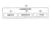
- FIG. 2 is a block diagram illustrating a configuration example of the multistage route allocation calculation unit 120.
- the multistage route allocation calculation unit 120 includes a capacity determination unit 121, a switching time determination unit 122, and a loop determination unit 123.
- the capacity determination unit 121 has a function of determining whether or not the network capacity of a target link to be allocated satisfies a predetermined condition. For example, the capacity determination unit 121 determines whether or not the multi-stage route allocation calculation unit 120 can use the network capacity reserved for the redundant path corresponding to the other active path. Then, it is determined whether or not the network capacity of the target link is sufficient to be usable.
- the capacity determination unit 121 shares the network capacity, which is reserved for other redundant paths, with the redundant path calculated when the redundant path is calculated in the multistage path allocation calculation unit 120 with other redundant paths. Even when it is determined whether or not it is possible, the same determination as described above is performed. That is, the capacity determination unit 121 determines whether or not the network capacity of the target link is sufficient to be shared.
- the switching time determination unit 122 has a function of determining whether the time required for multi-stage switching from the active path to the redundant path by the multi-stage path switching unit 140 when a failure occurs falls within the requested time. Have.
- the loop determination unit 123 has a function of determining whether or not a loop occurs when multistage switching from the active path to the redundant path is performed.
- a loop that occurs when multistage switching to a redundant path is performed, for example, is affected by a network failure that has occurred on a given link.
- the active path is the starting point of the affected active path.
- the redundant path using a predetermined link is required.
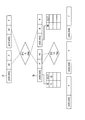
- FIG. 3 is an explanatory diagram showing an example of path information held by the dependency path management DB 150.
- One diamond shown in FIG. 3 represents one path.
- the name of the path, the network capacity per link used by the path, and the switching time required for switching from the active path to the redundant path are described.
- the rectangle described in the upper part of the rhombus represents the link constituting the route of the working path.
- the rectangle described in the lower part of the rhombus represents a link constituting a redundant path.
- a rectangle described as “(400, 410)” represents a link between the switch 400 and the switch 410 (hereinafter also referred to as a link A).
- link (a, b) means a link between the switch a and the switch b.
- the symbol in the rectangle represents the state of the network capacity held by the link represented by the rectangle.
- W indicates that there is a network capacity allocated to the working path.
- B represents that there is a network capacity allocated to the redundant path.
- F indicates that there is a network capacity that is not assigned to the path.
- P indicates that there is a network capacity shared between the working path and the redundant path.
- W”, “B”, and “P” are respectively connected to a path to which a network capacity related to each symbol is assigned by a broken line.
- F has no broken line because the network capacity associated with the symbol is not assigned to any path.
- the example shown in FIG. 3 shows a state in which the path f1 and the path f2 are assigned to the communication network 1000, respectively.
- the path f1 uses a path composed of links (400, 410) and links (410, 450) as an active path.
- the path f1 uses a path composed of links (400, 420) (hereinafter also referred to as links B) and links (420, 450) as redundant paths.
- the network capacity per link used by the path f1 is 5.
- the switching time required for switching the active path from the redundant path to the redundant path is 680.
- the path f2 uses a path composed of links (400, 420) and links (420, 450) as an active path. Further, the path f2 uses a path constituted by a link (400, 430), a link (430, 440), and a link (440, 450) as a redundant path.
- the network capacity per link used by the path f2 is 10.
- the switching time required for switching the active path from the active path to the redundant path is 780.
- the link B shown in FIG. 3 has a network capacity of “10”. As shown in FIG. 3, among the network capacity possessed by the link B, “5” is assigned to the redundant path of the path f1. Further, the active path of path f2 has a network capacity “5” allocated to the redundant path of path f1 and the remaining network capacity “5” possessed by link B, which is “10” in total. Network capacity is allocated (W).
- the working path of the path f2 uses the network capacity reserved for the redundant path of the path f1 (P). Before the failure occurs, the working capacity of the path f2 can use the network capacity “5” reserved for the redundant path of the path f1.
- path f1 depends on path f2.”
- the state of the network capacity of the link (410, 450) is the same as the state of the network capacity of the link (400, 410).
- the state of the network capacity of the link (420, 450) is the same as the state of the network capacity of the link (400, 420).
- path f1 is IN of the table of link (400, 420) and IN of the table of link (420, 450). Respectively. Further, as shown in FIG. 3, the path f2 is stored in OUT of the table of the link (400, 420) and OUT of the table of the link (420, 450), respectively.
- the links (400, 430) shown in FIG. 3 have a network capacity of “10”.
- the network capacity “10” possessed by the link (400, 430) is assigned to the redundant path of the path f2 (B).
- the state of the network capacity of the link (430, 440) and the state of the network capacity of the link (440, 450) are the same as the state of the network capacity of the link (400, 430). .
- the one-to-one path dependency between the path f1 and the path f2 is stored in the IN / OUT table.
- the IN / OUT table may store M vs. N path dependency relationships (M and N are both natural numbers).
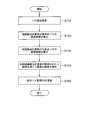
- FIG. 4 is a flowchart illustrating an operation of route assignment processing by the network control unit 100 according to the first embodiment.
- the client or server requests the network control unit 100 to set a path between the client and the server (step S110).
- the path set in this example is referred to as a path F1.
- the client or server designates the maximum time allowed as the time (switching time) required for switching from the active path F1 to the redundant path F1 when a network failure occurs.
- the route allocation calculation unit 110 of the network control unit 100 Upon receiving the request, the route allocation calculation unit 110 of the network control unit 100 receives the allocation request for the working path F1 and the redundant path F1 constituting the path F1.
- the path allocation calculation unit 110 Upon receiving the allocation request, the path allocation calculation unit 110 calculates the path of the working path F1 and the path of the redundant path F1. Further, the route allocation calculation unit 110 determines a network capacity allocated to the calculated route.
- the route allocation calculation unit 110 may calculate the route of the working path F1 and the route of the redundant system path F1 at the same time, or may calculate them separately. In this example, the route allocation calculation unit 110 calculates two routes simultaneously.
- the route allocation calculation unit 110 first calculates a candidate route for the active path F1 (step S120).
- the route assignment calculation unit 110 calculates route candidates using, for example, a k-shortest-paths algorithm.
- the route allocation calculation unit 110 calculates a candidate for the redundant path F1 for each candidate for the active path F1 calculated in step S120 (step S130).
- the route allocation calculating unit 110 calculates a candidate for the redundant path F1 using, for example, the k-shortest-paths algorithm, as in the case of calculating the candidate for the active path F1.
- the route allocation calculation unit 110 causes the multi-stage route allocation calculation unit 120 to select a combination of path route candidates satisfying the constraints from among the route candidates for the active path F1 and the route candidates for the redundant path F1 ( Step S140).
- the capacity determination unit 121 determines whether the combination of route candidates satisfies the constraint. That is, the capacity determination unit 121 determines whether or not a route that can secure the allocated network capacity is used.
- the multistage route allocation calculation unit 120 first refers to the path information stored in the dependency path management DB 150.
- the network capacity allocated to the working path determined in the processing of steps S120 to S130 is the network capacity that is reserved for the redundant path of other paths. Check whether or not.
- the multistage route allocation calculation unit 120 uses the route so that the reserved network capacity is used as it is. Select candidate combinations. When the network capacity is not reserved for the redundant path, the multistage route allocation calculation unit 120 selects a combination of route candidates so that free capacity is secured.
- the above restriction is that, for example, the time for switching from the active path to the redundant path is within a specified switching time.
- the switching time determination unit 122 determines whether a combination of route candidates satisfies a constraint.
- the switching time determination unit 122 is within the switching time when the path to which the network capacity has already been allocated is switched when a network failure occurs. It is determined whether it fits in. The switching time determination unit 122 makes the determination on the assumption that various network failures have occurred.
- the switching time determination unit 122 is within the switching time when the path to which the network capacity has already been allocated is switched when a network failure occurs. It is determined whether it fits in. The switching time determination unit 122 makes the determination on the assumption that various network failures have occurred.
- the loop determination unit 123 determines whether the combination of route candidates satisfies the constraint.
- the loop determination unit 123 determines whether or not a loop is generated in the path switching process when a network failure occurs.
- the loop determination unit 123 makes the determination assuming various network failures.
- the loop determination unit 123 determines whether or not a loop is generated in the path switching process when a network failure occurs when the redundant path F1 shares the network capacity of another redundant path. The loop determination unit 123 makes the determination assuming various network failures.
- the route allocation calculation unit 110 selects the best combination of the working path and the redundant path from the combinations selected by the multistage route allocation calculation unit 120.
- the best combination is, for example, the combination with the lowest cost, the combination with the smallest delay time, the combination with the smallest allocated network capacity, and the combination with the largest share of network capacity. That is, the user may select a condition suitable for the application as the best combination condition.
- the route assignment calculation unit 110 may select the redundant path after selecting the working path first. Further, the route allocation calculating unit 110 may select the working path after selecting the redundant path first.
- the route assignment calculation unit 110 When the best combination of the working path and the redundant path is determined, the route assignment calculation unit 110 notifies the multistage route assignment calculation unit 120 of information indicating the determined combination of paths. Next, the multistage route allocation calculation unit 120 updates the path information stored in the dependency path management DB 150 based on the received information (step S150). After the update, the network control unit 100 ends the route assignment process.
- FIG. 5 is an explanatory diagram showing another example of path information held by the dependency path management DB 150.
- the meaning of each notation shown in FIG. 5 is the same as the meaning of each notation shown in FIG.
- FIG. 5 shows that the path f2 has not been set yet.
- the network control unit 100 is requested to set the path f2 (step S110).
- the route allocation calculation unit 110 calculates route candidates for the active path f2 (step S120).
- the route allocation calculation unit 110 calculates a route including the link (400, 420) as a route candidate of the active path f2.
- the multistage route allocation calculation unit 120 updates the path information stored in the dependency path management DB 150 based on the information received from the route allocation calculation unit 110 (step S150). For the sake of simplicity in this example, the description of the processing in steps S130 to S140 is omitted.
- FIG. 6 is an explanatory diagram showing another example of the path information held by the dependency path management DB 150.
- FIG. 6 shows information after the path information held in the dependency path management DB 150 shown in FIG. 5 is updated by the multistage route allocation calculation unit 120.
- the network capacity “5” (B shown in FIG. 5) reserved for the redundant path of the path f1 is the working path of the path f2. (P shown in FIG. 6).
- the network capacity “5” (F shown in FIG. 5) that has not been assigned to any path is assigned to the working path of the path f2 (FIG. 6). W).
- the path f1 is stored in IN of the table of links (400, 420). Further, the path f2 is stored in OUT of the table of links (400, 420).
- the path information held by the dependency path management DB 150 is finally updated to the path information shown in FIG.
- An efficient route is, for example, a route in which the number of hops of a switch or router that passes through the route is small, or a route that has a short delay time.
- the reason is that the multi-stage route allocation calculation unit 120 allocates network capacity to the path so that the network capacity allocated to the redundant path is used in other active paths even when it is normal. This is because opportunities that can only be selected are reduced.
- control device 10 of the present embodiment may have a function of controlling communication processing in the communication network 1000 based on path information held by the dependency path management DB 150. Further, devices other than the control device 10 may control communication processing in the communication network 1000 based on path information held by the dependency path management DB 150.
- control apparatus 10 of this embodiment may be implement
- CPU Central * Processing * Unit
- dependency path management DB 150 may be realized by, for example, a RAM (Random Access Memory).
- each unit in the control device 10 of the present embodiment may be realized by a hardware circuit.
- the path allocation calculation unit 110, the multistage path allocation calculation unit 120, the path switching unit 130, the multistage path switching unit 140, and the dependent path management DB 150 are each realized by an LSI (Large Scale Integration). Further, they may be realized by a single LSI.
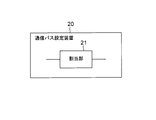
- FIG. 7 is a block diagram showing an outline of a communication path setting apparatus according to the present invention.
- the communication path setting device 20 configures a new communication path when a new communication path is set in a communication network in which a predetermined communication path composed of an active path and a redundant path is set.
- An allocation unit 21 (for example, multi-stage route allocation calculation) that allocates network capacity to the active path constituting a new communication path so that the network capacity reserved for the redundant path is shared between the active path and the redundant path Part 120).
- the communication path setting device can improve the usage rate of the network capacity.
- the allocation unit 21 shares the network capacity reserved for the redundant path constituting the predetermined communication path with the redundant path constituting the new communication path and the redundant path constituting the predetermined communication path. As described above, the network capacity may be allocated to the redundant path constituting the new communication path.
- the communication path setting device can reduce the total amount of network capacity allocated to the communication path.
- the assigning unit 21 may assign the network capacity determined to have a capacity satisfying a predetermined condition to an active path constituting a new communication path or a redundant path constituting a new communication path.
- the communication path setting device can allocate network capacity so that congestion does not occur.
- the allocating unit 21 renews the network capacity so that the time taken until the path used as the communication path is switched from the active path to the redundant path when a failure occurs in the communication network falls within a predetermined time. May be assigned to an active path constituting a simple communication path or a redundant path constituting a new communication path.
- the communication path setting device can allocate network capacity so that an SLA (Service Level Agreement) related to a communication network failure is satisfied.
- SLA Service Level Agreement
- the allocating unit 21 determines the network capacity so that all communication paths are normally used after the path used as the communication path is switched from the working path to the redundant path when a failure occurs in the communication network. May be assigned to an active path constituting a new communication path or a redundant path constituting a new communication path.
- the communication path setting device 20 includes a storage unit (for example, the dependency path management DB 150) that stores communication path information that is information related to the communication path set in the communication network, and the communication path information includes the communication path. Information on the allocated network capacity may be included.
- a storage unit for example, the dependency path management DB 150
- the communication path setting device can manage communication path information.
- the information on the network capacity allocated to the plurality of communication paths may include information indicating the relationship between the plurality of communication paths.
- the communication path setting device can more easily switch communication paths in multiple stages.
- the communication path setting device 20 may include a switching unit (for example, the path switching unit 130) that switches the path used as the communication path from the active system path to the redundant system path.
- the communication path setting device 20 may include a multistage switching unit (for example, a multistage path switching unit 140) that switches paths in multiple stages.
- the communication path setting device can switch a path to be used when a communication network failure occurs.
- the network capacity reserved for the redundant path that is not normally used is utilized.
- Control apparatus 20 Communication path setting apparatus 21 Allocation part 100 Network control part 110 Path allocation calculation part 120 Multistage route allocation calculation part 121 Capacity determination part 122 Switching time determination part 123 Loop determination part 130 Path switching part 140 Multistage path switching part 150 Dependence Path management database (DB) 200, 210 Client 300, 310 Server 400, 410, 420, 430, 440, 450 Switch 1000 Communication network
- DB Dependence Path management database
Landscapes
- Engineering & Computer Science (AREA)
- Computer Networks & Wireless Communication (AREA)
- Signal Processing (AREA)
- Computer Security & Cryptography (AREA)
- Data Exchanges In Wide-Area Networks (AREA)
Abstract
L'invention concerne un appareil de réglage de trajet de communication (20) comprenant une unité d'attribution (21) qui, lorsqu'un nouveau trajet de communication est défini dans un réseau de communication dans lequel des trajets de communication prédéterminés constitués par un trajet de système en cours et un trajet de système redondant sont définis, attribue une capacité de réseau au trajet de système en cours constituant le nouveau trajet de communication de manière qu'une capacité de réseau réservée pour le trajet de système redondant soit partagée par le trajet de système en cours constituant le nouveau trajet de communication et par le trajet de système redondant.
Priority Applications (2)
| Application Number | Priority Date | Filing Date | Title |
|---|---|---|---|
| JP2018528472A JPWO2018016300A1 (ja) | 2016-07-21 | 2017-06-30 | 通信パス設定装置、通信パス設定方法および通信パス設定プログラム |
| US16/318,752 US20190245807A1 (en) | 2016-07-21 | 2017-06-30 | Communication path setting apparatus, communication path setting method and communication path setting program |
Applications Claiming Priority (2)
| Application Number | Priority Date | Filing Date | Title |
|---|---|---|---|
| US201662364993P | 2016-07-21 | 2016-07-21 | |
| US62/364993 | 2016-07-21 |
Publications (1)
| Publication Number | Publication Date |
|---|---|
| WO2018016300A1 true WO2018016300A1 (fr) | 2018-01-25 |
Family
ID=60992976
Family Applications (1)
| Application Number | Title | Priority Date | Filing Date |
|---|---|---|---|
| PCT/JP2017/024231 Ceased WO2018016300A1 (fr) | 2016-07-21 | 2017-06-30 | Appareil de réglage de trajet de communication, procédé de réglage de trajet de communication et programme de réglage de trajet de communication |
Country Status (3)
| Country | Link |
|---|---|
| US (1) | US20190245807A1 (fr) |
| JP (1) | JPWO2018016300A1 (fr) |
| WO (1) | WO2018016300A1 (fr) |
Citations (2)
| Publication number | Priority date | Publication date | Assignee | Title |
|---|---|---|---|---|
| JP2002261803A (ja) * | 2001-02-27 | 2002-09-13 | Mitsubishi Electric Corp | ラベルスイッチングパス設定方法 |
| JP2003273904A (ja) * | 2002-03-14 | 2003-09-26 | Nec Corp | 経路制御方法、経路制御装置 |
Family Cites Families (2)
| Publication number | Priority date | Publication date | Assignee | Title |
|---|---|---|---|---|
| US7463580B2 (en) * | 2005-12-15 | 2008-12-09 | Corrigent Systems, Ltd. | Resource sharing among network tunnels |
| CN101902382B (zh) * | 2009-06-01 | 2015-01-28 | 中兴通讯股份有限公司 | 一种以太单环网地址刷新方法及系统 |
-
2017
- 2017-06-30 WO PCT/JP2017/024231 patent/WO2018016300A1/fr not_active Ceased
- 2017-06-30 JP JP2018528472A patent/JPWO2018016300A1/ja active Pending
- 2017-06-30 US US16/318,752 patent/US20190245807A1/en not_active Abandoned
Patent Citations (2)
| Publication number | Priority date | Publication date | Assignee | Title |
|---|---|---|---|---|
| JP2002261803A (ja) * | 2001-02-27 | 2002-09-13 | Mitsubishi Electric Corp | ラベルスイッチングパス設定方法 |
| JP2003273904A (ja) * | 2002-03-14 | 2003-09-26 | Nec Corp | 経路制御方法、経路制御装置 |
Also Published As
| Publication number | Publication date |
|---|---|
| US20190245807A1 (en) | 2019-08-08 |
| JPWO2018016300A1 (ja) | 2019-05-09 |
Similar Documents
| Publication | Publication Date | Title |
|---|---|---|
| CN105900393B (zh) | 用于sdn中分布式流量工程的流行为驱动的动态分区 | |
| US10581679B1 (en) | Migrating services in data communication networks | |
| US20150334002A1 (en) | Techniques for end-to-end network bandwidth optimization using software defined networking | |
| CN106664214B (zh) | 一种虚拟网络的故障恢复方法和装置 | |
| JP2012209928A (ja) | 動的フローレットスケジューリングシステムおよび方法 | |
| US10216593B2 (en) | Distributed processing system for use in application migration | |
| JP6470426B2 (ja) | リソース割当装置及びリソース割当方法 | |
| JP7127541B2 (ja) | 光ネットワーク制御装置、光ノード装置、および光パス設定方法 | |
| Denis et al. | Ebb: Reliable and evolvable express backbone network in meta | |
| JPWO2018220708A1 (ja) | 資源割当システム、管理装置、方法およびプログラム | |
| WO2015074396A1 (fr) | Procédé de configuration automatique, dispositif, et système de réseau défini par logiciel | |
| KR20100134042A (ko) | Wdm 메시 네트워크들에서 보호 공유의 방법 | |
| US10075364B2 (en) | Method and apparatus for self-tuned adaptive routing | |
| US10785103B2 (en) | Method and system for managing control connections with a distributed control plane | |
| JP2017500816A (ja) | 大規模データセンターネットワークのためのトラフィック工学 | |
| US11979335B2 (en) | Network controller | |
| CN114697256B (zh) | 基于集中式控制器的动态网络带宽分配与管理 | |
| WO2017197481A1 (fr) | Procédés et systèmes de reprise après défaillance dans un environnement de réseau virtuel | |
| US20150188831A1 (en) | System and Method for Traffic Engineering Using Link Buffer Status | |
| KR101541168B1 (ko) | 소프트웨어 정의 네트워크 환경에서 컨트롤러의 플로우에 대한 경로 제어방법 | |
| WO2018016300A1 (fr) | Appareil de réglage de trajet de communication, procédé de réglage de trajet de communication et programme de réglage de trajet de communication | |
| JP6288633B2 (ja) | ネットワーク制御方法 | |
| JP6472312B2 (ja) | 機能部割当装置及び機能部割当方法 | |
| CN107872404A (zh) | 业务分片处理方法、装置及软件定义网络控制器 | |
| CN113596109A (zh) | 业务请求运行方法、系统、装置、设备和存储介质 |
Legal Events
| Date | Code | Title | Description |
|---|---|---|---|
| 121 | Ep: the epo has been informed by wipo that ep was designated in this application |
Ref document number: 17830820 Country of ref document: EP Kind code of ref document: A1 |
|
| ENP | Entry into the national phase |
Ref document number: 2018528472 Country of ref document: JP Kind code of ref document: A |
|
| NENP | Non-entry into the national phase |
Ref country code: DE |
|
| 122 | Ep: pct application non-entry in european phase |
Ref document number: 17830820 Country of ref document: EP Kind code of ref document: A1 |