WO2018016352A1 - リアクトル、およびリアクトルの製造方法 - Google Patents
リアクトル、およびリアクトルの製造方法 Download PDFInfo
- Publication number
- WO2018016352A1 WO2018016352A1 PCT/JP2017/024972 JP2017024972W WO2018016352A1 WO 2018016352 A1 WO2018016352 A1 WO 2018016352A1 JP 2017024972 W JP2017024972 W JP 2017024972W WO 2018016352 A1 WO2018016352 A1 WO 2018016352A1
- Authority
- WO
- WIPO (PCT)
- Prior art keywords
- winding
- coil
- case
- reactor
- core
- Prior art date
- Legal status (The legal status is an assumption and is not a legal conclusion. Google has not performed a legal analysis and makes no representation as to the accuracy of the status listed.)
- Ceased
Links
Images




Classifications
-
- H—ELECTRICITY
- H01—ELECTRIC ELEMENTS
- H01F—MAGNETS; INDUCTANCES; TRANSFORMERS; SELECTION OF MATERIALS FOR THEIR MAGNETIC PROPERTIES
- H01F37/00—Fixed inductances not covered by group H01F17/00
-
- H—ELECTRICITY
- H01—ELECTRIC ELEMENTS
- H01F—MAGNETS; INDUCTANCES; TRANSFORMERS; SELECTION OF MATERIALS FOR THEIR MAGNETIC PROPERTIES
- H01F27/00—Details of transformers or inductances, in general
- H01F27/28—Coils; Windings; Conductive connections
- H01F27/32—Insulating of coils, windings, or parts thereof
- H01F27/327—Encapsulating or impregnating
-
- H—ELECTRICITY
- H01—ELECTRIC ELEMENTS
- H01F—MAGNETS; INDUCTANCES; TRANSFORMERS; SELECTION OF MATERIALS FOR THEIR MAGNETIC PROPERTIES
- H01F1/00—Magnets or magnetic bodies characterised by the magnetic materials therefor; Selection of materials for their magnetic properties
- H01F1/01—Magnets or magnetic bodies characterised by the magnetic materials therefor; Selection of materials for their magnetic properties of inorganic materials
- H01F1/03—Magnets or magnetic bodies characterised by the magnetic materials therefor; Selection of materials for their magnetic properties of inorganic materials characterised by their coercivity
- H01F1/12—Magnets or magnetic bodies characterised by the magnetic materials therefor; Selection of materials for their magnetic properties of inorganic materials characterised by their coercivity of soft-magnetic materials
- H01F1/14—Magnets or magnetic bodies characterised by the magnetic materials therefor; Selection of materials for their magnetic properties of inorganic materials characterised by their coercivity of soft-magnetic materials metals or alloys
- H01F1/20—Magnets or magnetic bodies characterised by the magnetic materials therefor; Selection of materials for their magnetic properties of inorganic materials characterised by their coercivity of soft-magnetic materials metals or alloys in the form of particles, e.g. powder
-
- H—ELECTRICITY
- H01—ELECTRIC ELEMENTS
- H01F—MAGNETS; INDUCTANCES; TRANSFORMERS; SELECTION OF MATERIALS FOR THEIR MAGNETIC PROPERTIES
- H01F27/00—Details of transformers or inductances, in general
- H01F27/02—Casings
-
- H—ELECTRICITY
- H01—ELECTRIC ELEMENTS
- H01F—MAGNETS; INDUCTANCES; TRANSFORMERS; SELECTION OF MATERIALS FOR THEIR MAGNETIC PROPERTIES
- H01F27/00—Details of transformers or inductances, in general
- H01F27/24—Magnetic cores
-
- H—ELECTRICITY
- H01—ELECTRIC ELEMENTS
- H01F—MAGNETS; INDUCTANCES; TRANSFORMERS; SELECTION OF MATERIALS FOR THEIR MAGNETIC PROPERTIES
- H01F27/00—Details of transformers or inductances, in general
- H01F27/28—Coils; Windings; Conductive connections
- H01F27/30—Fastening or clamping coils, windings, or parts thereof together; Fastening or mounting coils or windings on core, casing, or other support
- H01F27/306—Fastening or mounting coils or windings on core, casing or other support
-
- H—ELECTRICITY
- H01—ELECTRIC ELEMENTS
- H01F—MAGNETS; INDUCTANCES; TRANSFORMERS; SELECTION OF MATERIALS FOR THEIR MAGNETIC PROPERTIES
- H01F27/00—Details of transformers or inductances, in general
- H01F27/24—Magnetic cores
- H01F27/255—Magnetic cores made from particles
Definitions
- the present invention relates to a reactor and a method for manufacturing the reactor.
- This application claims priority based on Japanese Patent Application No. 2016-144591 filed on Jul. 22, 2016, and incorporates all the contents described in the aforementioned Japanese application.
- Patent Document 1 discloses a reactor that includes a coil having a pair of winding portions arranged in parallel and a magnetic core that forms a closed magnetic circuit, and is used as a component of a converter of a hybrid vehicle.
- the magnetic core can be divided into an inner core portion disposed inside the winding portion and an outer core portion disposed outside the winding portion.
- the coil / magnetic core combination is housed inside the case.
- the reactor of the present disclosure is A coil having a pair of windings arranged in parallel; A magnetic core having an inner core portion disposed inside the winding portion and an outer core portion exposed from the winding portion; A reactor for storing a combination of the coil and the magnetic core;
- the case includes a bottom plate portion on which the assembly is placed, and a side wall portion having a portion facing the outer peripheral surface of the outer core portion,
- the magnetic core is composed of a composite material including soft magnetic powder and resin, and is bonded to the upper surface of the bottom plate portion and the inner peripheral surface of the side wall portion at the position of the outer core portion,
- the side wall portion includes an outer surface in the parallel direction in one of the winding portions and an outer surface in the parallel direction in the other winding portion when the direction in which the winding portions are arranged in parallel is a parallel direction.
- a notch for exposing at least one of the cases to the outside is provided.
- the manufacturing method of the reactor of this indication is as follows.
- a combination of a coil having a pair of winding portions arranged in parallel, an inner core portion disposed inside the winding portion, and a magnetic core having an outer core portion exposed from the winding portion is used as a case.
- a method for manufacturing a reactor to be housed When the direction in which the winding parts are arranged in parallel is the parallel direction, the case for storing the coil includes the outer side surface in the parallel direction in one of the winding parts and the parallel direction in the other winding part.
- the reactor of the present disclosure includes a case that protects the magnetic core, and is excellent in heat dissipation.
- the manufacturing method of the reactor of this indication can be provided with the case which protects a magnetic core, and can produce the reactor of this indication excellent in heat dissipation.
- the reactor according to the embodiment is A coil having a pair of windings arranged in parallel; A magnetic core having an inner core portion disposed inside the winding portion and an outer core portion exposed from the winding portion; A reactor for storing a combination of the coil and the magnetic core;
- the case includes a bottom plate portion on which the assembly is placed, and a side wall portion having a portion facing the outer peripheral surface of the outer core portion,
- the magnetic core is composed of a composite material including soft magnetic powder and resin, and is bonded to the upper surface of the bottom plate portion and the inner peripheral surface of the side wall portion at the position of the outer core portion,
- the side wall portion includes an outer surface in the parallel direction in one of the winding portions and an outer surface in the parallel direction in the other winding portion when the direction in which the winding portions are arranged in parallel is a parallel direction.
- a notch for exposing at least one of the cases to the outside is provided.
- the outer core portion made of the composite material can be physically protected.
- the outer surface of one winding part of the coil and the outer surface of the other winding part is exposed from the case, heat is easily released from the coil to the outside of the case.
- the reactor is excellent in heat dissipation.
- the configuration in which the outer surface of at least one winding portion is exposed from the case also has an advantage that the constituent material of the case can be saved.
- the reactor according to the embodiment since the magnetic core is joined to the bottom plate part and the side wall part, heat easily propagates from the magnetic core to the case, and heat is easily released to the outside of the case through the case. Therefore, the reactor according to the embodiment is excellent in heat dissipation.
- the side wall portion is A pair of core facing portions facing the outer peripheral surface of the outer core portion; One of the notch portions for exposing the outer surface of one of the winding portions to the outside of the case; The other said notch part which exposes the said outer side surface of the said other winding part to the outer side of the said case can be mentioned.
- the heat dissipation of the reactor can be improved by adopting the above-described configuration in which the outer surfaces of both winding portions are exposed from the case.
- the side wall portion is A pair of core facing portions facing the outer peripheral surface of the outer core portion; A pair of core facing portions, a coil facing portion facing the outer surface of one of the winding portions, or the outer surface of the other winding portion; The notch portion that exposes the outer surface of the winding portion opposite to the winding portion covered by the coil facing portion to the outside of the case; The form provided with the heat radiating material interposed between the said coil opposing part and the said winding part can be mentioned.
- heat dissipation material between the coil facing portion and the side surface of the coil, heat dissipation through the coil facing portion can be improved.
- heat dissipation material for example, heat dissipating grease having excellent thermal conductivity can be used.
- the end face interposed member By providing the end face interposed member, it is possible to reliably ensure insulation between the outer core portion and the winding portion.
- the composite material when the composite material is filled in the case when manufacturing the reactor, by contacting at least a part of the outer surface of the end surface interposed member with the inner peripheral surface of the side wall portion of the case, the end surface interposed member and the side wall portion The composite material can be prevented from leaking through the gaps.
- the end surface interposed member includes an overhanging portion projecting outward in the parallel direction at a position on the winding portion side of the outer surface in the parallel direction of the winding portions,
- the side where the end of the winding constituting the winding part is arranged is the winding end side, and the side where the connecting part for connecting the pair of winding parts is arranged is the connecting part side.
- the projecting part provided in the end surface interposing member on the part side may have a tapered shape that inclines toward the winding end part side toward the tip in the projecting direction of the projecting part. .
- the overhanging portion provided on the end surface interposed member on the connecting portion side is a portion that is pressed when the composite material is filled in the case in manufacturing the reactor.
- the end face interposed member on the winding end side is pressed against the case by pressing the end face interposed member on the connecting part side toward the winding end via the overhang, and the end of the coil winding is the case.
- the overhanging portion of the end surface interposed member on the winding end side is a portion that is a stopper against the case.
- the coil includes a coil mold portion made of an insulating resin,
- the coil mold part is A turn covering portion for integrating the turns of the winding portion;
- coated part interposed between the end surface of the said winding part and the said outer core part can be mentioned.
- the casing is filled with a composite material when manufacturing the reactor by adopting a configuration in which the inner peripheral surface of the side wall portion is in contact with at least a part of the outer surface in the parallel direction of the end surface covering portion of the coil mold portion. When doing, it can suppress that a composite material leaks from the clearance gap between an end surface coating
- the side wall portion includes a pair of core facing portions facing the outer peripheral surface of the outer core portion,
- the core facing portion includes a retaining recess formed by a part of the inner peripheral surface on the side of the bottom plate being recessed toward the side away from the outer core portion, A form in which a part of the outer core part enters the retaining recess is exemplified.
- the reactor of the embodiment is manufactured by filling the inside of the case with a composite material after arranging the coil inside the case, as shown in the reactor manufacturing method of the embodiment described later. Therefore, it is difficult to provide a gap portion at the position of the inner core portion disposed inside the coil winding portion. Even when a member that becomes a gap portion is arranged inside the winding portion when filling the composite material, it is difficult to fix the member in place due to the winding portion being in the way, and filling the composite material This is because the position of the member changes with pressure. On the other hand, if it is a position outside the coil, there is no problem that it is difficult to fix the member that becomes the gap part due to the coil, and the predetermined gap part can be formed in the magnetic core. By forming the gap portion in the magnetic core, it becomes easy to adjust the magnetic characteristics of the magnetic core.
- the manufacturing method of the reactor which concerns on ⁇ 9> embodiment is as follows.
- a combination of a coil having a pair of winding portions arranged in parallel, an inner core portion disposed inside the winding portion, and a magnetic core having an outer core portion exposed from the winding portion is used as a case.
- a method for manufacturing a reactor to be housed When the direction in which the winding parts are arranged in parallel is the parallel direction, the case for storing the coil includes the outer side surface in the parallel direction in one of the winding parts and the parallel direction in the other winding part.
- the reactor of the embodiment can be manufactured simply by arranging the coil in the case and filling the case with the composite material.
- the coil is housed in the case in a state where the end face interposed member is in contact with the end face of the coil, and the edge of the notch provided in the case is sealed with the end face interposed member.
- the form can be mentioned.
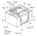
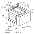
- a reactor 1 shown in FIG. 1 includes a combined body 10 in which a coil 2, a magnetic core 3, and end surface interposed members 4A and 4B are combined, and a case 6 that houses the combined body 10.
- One of the features of the reactor 1 is a state in which the combined body 10 is housed by a case.
- each structure with which the reactor 1 is provided is demonstrated in detail, and the manufacturing method of the reactor 1 is demonstrated then.
- the coil 2 of the present embodiment includes a pair of winding parts 2A and 2B and a connecting part 2R that connects both the winding parts 2A and 2B.
- Each winding portion 2A, 2B is a portion in which the winding 2w is spirally wound, and is formed in a hollow cylindrical shape with the same number of turns and the same winding direction, and is arranged in parallel so that the respective axial directions are parallel to each other. ing.
- the coil 2 is manufactured with one winding 2w.
- the coil 2 may be manufactured by connecting the winding parts 2A and 2B manufactured by separate windings.
- Each winding part 2A, 2B of this embodiment is formed in a rectangular tube shape.
- the rectangular tube-shaped winding parts 2A and 2B are winding parts whose end face shape is a square shape (including a square shape) with rounded corners.
- the winding portions 2A and 2B may be formed in a cylindrical shape.
- the cylindrical winding portion is a winding portion whose end face shape is a closed curved surface shape (an elliptical shape, a perfect circle shape, a race track shape, etc.).
- the coil 2 including the winding portions 2A and 2B is a coated wire having an insulating coating made of an insulating material on the outer periphery of a conductor such as a flat wire or a round wire made of a conductive material such as copper, aluminum, magnesium, or an alloy thereof.
- a conductor such as a flat wire or a round wire made of a conductive material such as copper, aluminum, magnesium, or an alloy thereof.
- the conductor is made of a copper rectangular wire (winding 2w)
- the insulating coating is made of enamel (typically polyamideimide) by edgewise winding, whereby each winding portion 2A, 2B is formed.
- Both end portions 2a and 2b of the coil 2 are extended from the winding portions 2A and 2B and connected to a terminal member (not shown).
- the insulating coating such as enamel is peeled off at both ends 2a and 2b.
- An external device such as a power source for supplying power is connected to the coil 2 through the terminal member.
- the winding portions 2A and 2B of the coil 2 are preferably integrated with resin.
- the winding portions 2A and 2B of the coil 2 are individually integrated with an integrated resin.
- the integrated resin of this example is configured by fusing a coating layer of a heat-sealing resin formed on the outer periphery of the winding 2w (further outer periphery of an insulating coating such as enamel) and is very thin. Therefore, even if each turn of winding part 2A, 2B is integrated with integral resin, the shape of the turn of winding part 2A, 2B and the boundary of a turn are in the state which can be seen from an external appearance.
- a thermosetting resin such as an epoxy resin, a silicone resin, or an unsaturated polyester can be used.
- the magnetic core 3 includes an outer core portion 32 disposed outside the winding portions 2A and 2B and an inner core portion disposed inside the winding portions 2A and 2B. Can be divided.
- the outer core portion 32 and the inner core portion are integrally connected.
- the magnetic core 3 is composed of a composite material including soft magnetic powder and resin.
- Soft magnetic powder is an aggregate of magnetic particles composed of an iron group metal such as iron or an alloy thereof (Fe—Si alloy, Fe—Ni alloy, etc.).
- the magnetic core 3 is formed by filling the case 6 with a composite material after the coil 2 is housed in the case 6 as shown in a reactor manufacturing method described later. Therefore, the outer core portion 32 of the magnetic core 3 is joined to the inner peripheral surface of the case 6.
- the end surface interposed members 4 ⁇ / b> A and 4 ⁇ / b> B are members that ensure insulation between the end surfaces of the winding portions 2 ⁇ / b> A and 2 ⁇ / b> B and the outer core portion 32 (see FIGS. 1 and 2).
- the end surface interposing members 4A and 4B are, for example, polyphenylene sulfide (PPS) resin, polytetrafluoroethylene (PTFE) resin, liquid crystal polymer (LCP), polyamide (PA) resin such as nylon 6 or nylon 66, polybutylene terephthalate (PBT).
- the end surface interposed members 4A and 4B can be formed of a thermosetting resin such as an unsaturated polyester resin, an epoxy resin, a urethane resin, or a silicone resin.
- the resin may contain a ceramic filler to improve the heat dissipation properties of the end surface interposed members 4A and 4B.
- the ceramic filler for example, nonmagnetic powder such as alumina or silica can be used.
- the end surface interposing members 4A and 4B are composed of a rectangular frame portion 40 and an end surface contact portion 41 that is a B-shaped plate material that contacts the end surfaces of the winding portions 2A and 2B.
- the rectangular frame portion 40 of the end surface interposed member 4B is longer in the axial direction of the winding portions 2A and 2B than the rectangular frame portion 40 of the end surface interposed member 4A.
- the rectangular frame portion 40 of the end surface interposed member 4B is elongated from the position of the outer surface 400 (the surface in the parallel direction of the winding portions 2A and 2B) of the end surface interposed member 4B in the reactor manufacturing method described later. This is to prevent the composite material from leaking.
- turn storage portions 41 s On the surface of the end surface contact portion 41 on the coil 2 side, two turn storage portions 41 s (particularly refer to the end surface interposed member 4 ⁇ / b> A) for storing the axial ends of the winding portions 2 ⁇ / b> A and 2 ⁇ / b> B are formed.
- the turn accommodating portion 41s is a recess along the shape of the end surface in the axial direction of the winding portions 2A and 2B, and is formed to bring the entire end surface into surface contact with the end surface interposed members 4A and 4B.
- the end surface contact portion 41 is provided with a pair of cylindrical portions 41c each having a through hole 41h.
- the cylindrical part 41c is inserted into the winding parts 2A and 2B.
- the through hole 41h serves as an inlet for filling the winding material 2A, 2B with the composite material in the reactor manufacturing method described later.
- the cylindrical portion 41c is inserted into the winding portions 2A and 2B, determines the positions of the end surface interposed members 4A and 4B with respect to the winding portions 2A and 2B, and is a composite material filled in the winding portions 2A and 2B. Has a function of suppressing leakage from the end faces of the winding portions 2A and 2B.
- the end surface interposing members 4A and 4B project outside the outer surface 400 in the parallel direction of the winding parts 2A and 2B to the outer side in the parallel direction of the winding parts 2A and 2B at the position on the winding parts 2A and 2B side.
- a pair of overhang portions 42 are provided.
- the projecting portion 42 of the end surface interposed member 4A is formed to have a uniform thickness toward the tip in the projecting direction, but the projecting portion 42 of the end surface interposed member 4B is directed to the tip in the projecting direction. Accordingly, the taper shape is inclined toward the winding end side (slant upper left side of the drawing). The reason why the overhanging portion 42 of the end surface interposed member 4B has such a shape will be described in the description of the method for manufacturing the reactor described later.
- the case 6 includes a bottom plate portion 60 and a side wall portion 61.
- the bottom plate portion 60 and the side wall portion 61 may be integrally formed, or the separately prepared bottom plate portion 60 and the side wall portion 61 may be connected.
- a material of the case 6, for example, aluminum or an alloy thereof, a nonmagnetic metal such as magnesium or an alloy thereof, or a resin can be used. If the bottom plate portion 60 and the side wall portion 61 are separated, the materials of the two 60 and 61 can be different.
- the bottom plate portion 60 may be a nonmagnetic metal and the side wall may be a resin, or vice versa.
- the bottom plate portion 60 of this example is higher than the coil placement portion 60b on which the winding portions 2A and 2B are placed, and the coil placement portion 60b, and contacts the bottom surface of the outer core portion 32 (FIGS. 1 and 2).
- a core contact portion 60s is provided.
- the coil mounting part 60b is integrated with a connecting part 61C of a side wall part 61 described later, and the core contact part 60s is integrated with core facing parts 61A and 61B of the side wall part 61 described later.
- the side wall portion 61 of this example includes a pair of core facing portions 61A and 61B that face the outer peripheral surface of the outer core portion 32 (FIGS. 1 and 2), and a connecting portion 61C that connects these core facing portions 61A and 61B. ing.
- the connecting portion 61C is for connecting the core facing portions 61A and 61B to improve the rigidity of the side wall portion 61, and the height thereof is only enough to cover the bending corners on the lower side of the winding portions 2A and 2B. . Therefore, as shown in FIGS.
- the outer side surface in the parallel direction of the winding portion 2 ⁇ / b> A and the outer side surface in the parallel direction of the winding portion 2 ⁇ / b> B are exposed to the outside of the case 6. That is, the side wall 61 of the case 6 of this example is formed by notching a portion corresponding to the outer side surface in the parallel direction of the winding portions 2A and 2B, and the outer side surface is exposed to the outside of the case 6. In other words, the shape includes the notch 61E.
- the core facing portions 61A and 61B are formed in a substantially C shape when viewed from above.
- the core facing portions 61 ⁇ / b> A and 61 ⁇ / b> B include an end surface cover portion 61 e that covers an end surface of the outer core portion 32 (FIGS. 1 and 2) (an end surface opposite to the coil 2), and a side surface of the outer core portion 32.
- a pair of covering side cover portions 61s are formed in a C shape. The outer surface of the side cover portion 61s is substantially flush with the outer surfaces of the winding portions 2A and 2B.
- the side cover portion 61s includes a thin portion 600 formed by reducing the thickness in the vicinity of the edge on the coil 2 side, and the thin portion 600 is, as shown in FIGS. , 4B is covered.
- the composite material can be formed from the gap between the end surface interposed members 4A and 4B and the core facing portions 61A and 61B of the side wall portion 61 in the reactor manufacturing method described later. Leakage can be suppressed.
- the outer core portion 32 of the magnetic core 3 can be physically protected by the core facing portions 61 ⁇ / b> A and 61 ⁇ / b> B of the side wall portion 61 of the case 6.
- the heat dissipation of the reactor 1 is further improved. Can do.
- the reactor 1 of this example can be used as a component of a power conversion device such as a bidirectional DC-DC converter mounted on an electric vehicle such as a hybrid vehicle, an electric vehicle, or a fuel cell vehicle.
- a power conversion device such as a bidirectional DC-DC converter mounted on an electric vehicle such as a hybrid vehicle, an electric vehicle, or a fuel cell vehicle.
- the reactor 1 can be used while being immersed in a liquid refrigerant.
- the liquid refrigerant is not particularly limited, but when the reactor 1 is used in a hybrid vehicle, ATF (Automatic Transmission Fluid) or the like can be used as the liquid refrigerant.
- fluorinated inert liquids such as Fluorinert (registered trademark), chlorofluorocarbon refrigerants such as HCFC-123 and HFC-134a, alcohol refrigerants such as methanol and alcohol, and ketone refrigerants such as acetone are used as liquid refrigerants. You can also.
- the reactor manufacturing method generally includes the following steps. Refer to FIG. 3 mainly in description of the manufacturing method of a reactor. ⁇ Coil manufacturing process ⁇ Integration process ⁇ Case preparation process ⁇ Placement process ⁇ Filling process ⁇ Curing process
- the coil 2 is produced by preparing the winding 2w and winding a part of the winding 2w.
- a known winding machine can be used for winding the winding 2w.
- a heat-sealing resin coating layer can be formed as an integrated resin that integrates the turns of the winding portions 2A and 2B. The thickness of the coating layer can be appropriately selected. If the integrated resin is not provided, the winding 2w having no coating layer may be used, and the next integration process is not necessary.
- the winding portions 2A and 2B of the coil 2 manufactured in the coil manufacturing step are integrated with an integrated resin.
- the integrated resin can be formed by heat-treating the coil 2.
- the resin is applied to the outer periphery and inner periphery of the winding portions 2A and 2B of the coil 2, and the integrated resin is cured by curing the resin. It is good to form.
- the coil 2 is disposed inside the case 6.
- the first assembly in which the end surface interposed members 4 ⁇ / b> A and 4 ⁇ / b> B are assembled to the coil 2 is inserted into the case 6 from above the case 6.
- the outer side surfaces 400 of the end surface interposed members 4A and 4B are covered with the thin portions 600 of the core facing portions 61A and 61B (see also FIGS. 1 and 2).
- a space is formed between the inner peripheral surface of the core facing portion 61A (61B) and the end surface interposed member 4A (4B).
- the outer surface of the winding portion 2A is exposed from one notch portion 61E, and the outer surface of the winding portion 2B is exposed from the other notch portion 61E.
- the thermal radiation material which is not illustrated between the coil mounting part 60b and a 1st assembly.
- the heat radiating material for example, heat radiating grease or a foaming heat radiating sheet can be used.
- the composite material is filled from above the space formed between the inner peripheral surface of the core facing portion 61A (61B) and the end surface interposed member 4A (4B).
- the composite material filled in the case 6 accumulates between the core facing portion 61A (61B) and the end surface interposed member 4A (4B) and from the through holes 41h of the end surface interposed members 4A and 4B to the winding portions 2A and 2B. Also flows into the inside. Since the thin wall portion 600 of the core facing portion 61A (61B) covers the outer surface 400 of the end surface interposed member 4A (4B), the composite material extends from the position of the outer surface 400 of the end surface interposed member 4A (4B) to the outside of the case 6. Is prevented from leaking.
- a jig is inserted between the taper surface of the overhanging portion 42 of the end surface interposing member 4B and the edge of the side cover portion 61s of the core facing portion 61B of the case 6 to interpose the end surface.
- the member 4B is pressed toward the winding end.
- the rectangular frame portion 40 of the end surface interposed member 4B is formed longer, even when the end surface interposed member 4B is pressed toward the winding end portion, the overlap length between the outer surface 400 and the thin portion 600 is Sufficiently secured.
- the coil 2 By pressing the end face interposed member 4B toward the winding end, the coil 2 can be prevented from moving in the case 6 due to the filling pressure of the composite material, and the composite material can be prevented from leaking from the case 6. Further, by pressing the end face interposing member 4B toward the winding end, the positions of the ends 2a and 2b of the coil 2 with respect to the case 6 are accurately determined. Therefore, when the reactor 1 is disposed at a predetermined position in the vehicle It becomes easy to connect the reactor 1 to another member.
- the composite material is cured by heat treatment or the like.
- the one inside the winding parts 2A and 2B becomes the inner core part
- the one outside the winding parts 2A and 2B becomes the outer core part 32.
- the case 6 of the second embodiment is different from the case 6 of the first embodiment in the configuration of the side wall portion 61.
- the side wall portion 61 of the case 6 of this example includes a coil facing portion 61D in addition to the core facing portions 61A and 61B and the connecting portion 61C on the winding portion 2B side.
- the coil facing portion 61D is a member that faces the outer surface of the winding portion 2A. That is, the side wall portion 61 of the case 6 of this example is configured to surround three sides of the outer peripheral surface of the assembly 10 except for the outer surface of the winding portion 2B, and is wound at the position of the notch portion 61E.
- the outer surface of the portion 2B is exposed to the outside of the case 6.
- the coil facing portion 61D can be provided on the winding portion 2B side so that the outer surface of the winding portion 2A is exposed to the outside of the case 6.
- the reactor 1 of the present example is different from that of the first embodiment in that a coil mold portion 5 is provided on the coil 2 instead of the end face interposed member.
- the coil mold part 5 is comprised by insulating resin, for example, can use the material similar to the material which comprises the end surface interposition member of Embodiment 1.
- FIG. The coil mold part 5 may contain a filler in the same manner as the end face interposed member.
- the coil mold portion 5 includes a turn covering portion 50 that integrates the turns of the winding portions 2A and 2B, and an end surface covering portion 51 that is interposed between the end surfaces of the winding portions 2A and 2B and the outer core portion 32. Is provided. Furthermore, the coil mold part 5 includes a connecting part covering part 52 that covers a connecting part (not shown) of the winding parts 2A and 2B.
- the winding portions 2A and 2B of the rectangular tube-shaped coil 2 are divided into four corner portions formed by bending the winding 2w and a flat portion where the winding 2w is not bent.
- the turn covering portion 50 of this example integrates the turns of the winding portions 2A and 2B by covering the four corners of the winding portions 2A and 2B. Since the turn covering portion 50 does not cover the flat portions of the winding portions 2A and 2B, the heat release from the outer surface of the winding portions 2A and 2B is not hindered by the turn covering portion 50.
- the end surface covering portion 51 is provided so as to connect the turn covering portion 50 of the winding portion 2A and the turn covering portion 50 of the winding portion 2B.
- the end surface covering portion 51 is provided with a pair of through holes 51h and 51h communicating with the inside of the winding portions 2A and 2B.
- the through hole 51h has the same function as the through hole 41h of the end surface interposed members 4A and 4B of the first embodiment, that is, the function of guiding the composite material into the winding parts 2A and 2B when the reactor is manufactured. .
- the end surface covering portion 51 is formed in a frame shape protruding toward the side away from the coil 2 in the axial direction of the winding portions 2A and 2B.
- the outer surface (the surface in the parallel direction of the winding portions 2A and 2B) 510 of the frame-shaped end surface covering portion 51 abuts on the thin portion 600 of the core facing portions 61A and 61B of the case 6.
- the outer side surface 510 has the same function as the outer side surface 400 of the end surface interposed members 4A and 4B of the first embodiment, that is, the function of positioning the coil 2 in the case 6 and the function of suppressing the leakage of the composite material when the reactor 1 is manufactured. ing.
- the end surface covering portion 51 further includes a gap portion 51g provided between the pair of through holes 51h and 51h.
- the gap portion 51g is a plate-like member that protrudes toward the side away from the coil 2 in the axial direction of the winding portions 2A and 2B. As shown in FIGS. 4 and 5, the gap portion 51 g divides the outer core portion 32 in the parallel direction of the winding portions 2 ⁇ / b> A and 2 ⁇ / b> B and forms a gap at the position of the outer core portion 32.
- the thickness of the gap portion 51g By adjusting the thickness of the gap portion 51g, the magnetic characteristics of the magnetic core 3 can be adjusted.
- the gap portion 51g is not limited to the one that physically divides the outer core portion 32 into two, and may be any configuration that can divide the magnetic path of the outer core portion 32. That is, the gap 51g may be omitted where there is no influence on the magnetic path in the outer core 32. For example, even if the gap portion 51g has a length that does not reach the end face of the outer core portion 32 in the axial direction of the winding portions 2A and 2B, the gap portion 51g only needs to be interposed in a portion that becomes a magnetic path.
- the coil 2 and the case 6 which have the coil mold part 5 are prepared. Then, the coil 2 is inserted into the case 6 (arrangement step). At that time, the heat dissipating material 7 may be disposed on the inner peripheral surface of the coil facing portion 61D, and the heat dissipating material 70 may be disposed also on the coil placement portion 60b. By providing the heat dissipating materials 7 and 70, heat dissipation from the coil 2 to the case 6 can be promoted.
- the heat radiating materials 7 and 70 for example, heat radiating grease, foaming heat radiating sheets, or the like can be used.
- the composite material is filled from above the space (filling step).
- the composite material filled in the case 6 from the space accumulates between the core facing portion 61A (61B) and the end surface covering portion 51 to form the outer core portion 32 (FIGS. 4 and 5) and the through hole 51h.
- the inner core portion is formed by flowing into the winding portions 2A and 2B via the.
- the composite material since the thin portion 600 of the core facing portion 61A (61B) covers the outer surface 510 of the end surface covering portion 51, the composite material leaks from the position of the outer surface 510 of the end surface covering portion 51 to the outside of the case 6. Is suppressed.
- the magnetic core 3 of the present disclosure is configured by filling a case 6 with a composite material. That is, the outer core portion 32 of the magnetic core 3 is joined to the inner peripheral surface of the side wall portion 61 (the inner peripheral surfaces of the core facing portions 61A and 61B), so that the combination 10 is prevented from dropping from the case 6. .
- the case 6 it is preferable to provide the case 6 with a structure that prevents it from coming off. A specific example of the configuration that prevents the removal will be described with reference to FIG.
- FIG. 7 is a schematic perspective view of the case 6 used in the third embodiment.
- the case 6 of FIG. 7 is almost the same as the case 6 of FIG. 3 of the first embodiment, but differs from the case 6 of the first embodiment in that a retaining recess 61d is provided on the inner peripheral surface of the core facing portion 61A.
- a retaining recess 61d similar to the core facing portion 61A is provided on the inner peripheral surface of the core facing portion 61B.
- the retaining recess 61d is formed by recessing a part of the inner peripheral surface of the end surface cover 61e of the core facing portion 61A on the side of the bottom plate portion 60 away from the outer core portion 32 (see FIG. 1). If the case 6 having such a retaining recess 61d is filled with the composite material, a part of the outer core portion 32 enters the retaining recess 61d and the outer core portion 32 is caught by the retaining recess 61d. By this catching, it is possible to suppress the union 10 from dropping from the case 6.
- the retaining recess 61d can be provided at the position of the side cover 61s.
- the retaining recess 61d can also be applied to the case 6 of the second embodiment.
Landscapes
- Engineering & Computer Science (AREA)
- Power Engineering (AREA)
- Chemical & Material Sciences (AREA)
- Dispersion Chemistry (AREA)
- Insulating Of Coils (AREA)
- Coils Of Transformers For General Uses (AREA)
Abstract
並列された一対の巻回部を有するコイルと、内側コア部および外側コア部を有する磁性コアと、前記コイルと前記磁性コアの組合体を収納するケースと、を備えるリアクトルであって、前記ケースは、前記組合体を載置する底板部と、前記外側コア部の外周面に対向する部分を有する側壁部とを備え、前記磁性コアは、軟磁性粉末と樹脂とを含む複合材料で構成され、前記外側コア部の位置で前記底板部の上面と前記側壁部の内周面に接合しており、前記側壁部は、前記巻回部が並列される方向を並列方向としたとき、一方の前記巻回部における前記並列方向の外側面、および他方の前記巻回部における前記並列方向の外側面の少なくとも一方を前記ケースの外方に露出させる切欠き部を備える。
Description
本発明は、リアクトル、およびリアクトルの製造方法に関する。
本出願は、2016年7月22日付の日本国出願の特願2016-144591に基づく優先権を主張し、前記日本国出願に記載された全ての記載内容を援用するものである。
本出願は、2016年7月22日付の日本国出願の特願2016-144591に基づく優先権を主張し、前記日本国出願に記載された全ての記載内容を援用するものである。
特許文献1には、並列された一対の巻回部を有するコイルと、閉磁路を形成する磁性コアとを備え、ハイブリッド自動車のコンバータの構成部品などに利用されるリアクトルが開示されている。磁性コアは、巻回部の内部に配置される内側コア部と、巻回部の外部に配置される外側コア部と、に分けることができる。上記コイルと磁性コアの組合体は、ケースの内部に収納されている。
本開示のリアクトルは、
並列された一対の巻回部を有するコイルと、
前記巻回部の内部に配置される内側コア部、および前記巻回部から露出する外側コア部を有する磁性コアと、
前記コイルと前記磁性コアの組合体を収納するケースと、を備えるリアクトルであって、
前記ケースは、前記組合体を載置する底板部と、前記外側コア部の外周面に対向する部分を有する側壁部とを備え、
前記磁性コアは、軟磁性粉末と樹脂とを含む複合材料で構成され、前記外側コア部の位置で前記底板部の上面と前記側壁部の内周面に接合しており、
前記側壁部は、前記巻回部が並列される方向を並列方向としたとき、一方の前記巻回部における前記並列方向の外側面、および他方の前記巻回部における前記並列方向の外側面の少なくとも一方を前記ケースの外方に露出させる切欠き部を備える。
並列された一対の巻回部を有するコイルと、
前記巻回部の内部に配置される内側コア部、および前記巻回部から露出する外側コア部を有する磁性コアと、
前記コイルと前記磁性コアの組合体を収納するケースと、を備えるリアクトルであって、
前記ケースは、前記組合体を載置する底板部と、前記外側コア部の外周面に対向する部分を有する側壁部とを備え、
前記磁性コアは、軟磁性粉末と樹脂とを含む複合材料で構成され、前記外側コア部の位置で前記底板部の上面と前記側壁部の内周面に接合しており、
前記側壁部は、前記巻回部が並列される方向を並列方向としたとき、一方の前記巻回部における前記並列方向の外側面、および他方の前記巻回部における前記並列方向の外側面の少なくとも一方を前記ケースの外方に露出させる切欠き部を備える。
本開示のリアクトルの製造方法は、
並列された一対の巻回部を有するコイルと、前記巻回部の内部に配置される内側コア部、および前記巻回部から露出する外側コア部を有する磁性コアと、の組合体をケースに収納させるリアクトルの製造方法であって、
前記巻回部が並列される方向を並列方向としたとき、前記コイルを収納する前記ケースとして、一方の前記巻回部における前記並列方向の外側面および他方の前記巻回部における前記並列方向の外側面の少なくとも一方を露出させる切欠き部を設けた側壁部を備えるケースを用意するケース準備工程と、
前記コイルを前記ケースの内部に収納する配置工程と、
前記コイルの前記巻回部の端面と前記ケースとの間に、軟磁性粉末と樹脂を含む複合材料を充填し、前記複合材料で構成される前記磁性コアを形成する充填工程と、
を備える。
並列された一対の巻回部を有するコイルと、前記巻回部の内部に配置される内側コア部、および前記巻回部から露出する外側コア部を有する磁性コアと、の組合体をケースに収納させるリアクトルの製造方法であって、
前記巻回部が並列される方向を並列方向としたとき、前記コイルを収納する前記ケースとして、一方の前記巻回部における前記並列方向の外側面および他方の前記巻回部における前記並列方向の外側面の少なくとも一方を露出させる切欠き部を設けた側壁部を備えるケースを用意するケース準備工程と、
前記コイルを前記ケースの内部に収納する配置工程と、
前記コイルの前記巻回部の端面と前記ケースとの間に、軟磁性粉末と樹脂を含む複合材料を充填し、前記複合材料で構成される前記磁性コアを形成する充填工程と、
を備える。
[本開示が解決しようとする課題]
ケースを備えるリアクトルにおいて、軟磁性粉末と樹脂とを含む複合材料で磁性コアを構成することが検討されている。その場合、組合体を収納するケースによって複合材料の磁性コアを物理的に保護できる。しかし、ケースによって組合体の全周が囲まれることで、組合体から外部への放熱が妨げられる場合がある。
ケースを備えるリアクトルにおいて、軟磁性粉末と樹脂とを含む複合材料で磁性コアを構成することが検討されている。その場合、組合体を収納するケースによって複合材料の磁性コアを物理的に保護できる。しかし、ケースによって組合体の全周が囲まれることで、組合体から外部への放熱が妨げられる場合がある。
そこで、本開示は、磁性コアを保護するケースを備え、かつ放熱性に優れるリアクトルを提供することを目的の一つとする。また、本開示は、磁性コアを保護するケースを備え、かつ放熱性に優れるリアクトルを作製できるリアクトルの製造方法を提供することを目的の一つとする。
[本開示の効果]
本開示のリアクトルは、磁性コアを保護するケースを備え、かつ放熱性に優れる。
本開示のリアクトルは、磁性コアを保護するケースを備え、かつ放熱性に優れる。
本開示のリアクトルの製造方法は、磁性コアを保護するケースを備え、かつ放熱性に優れる本開示のリアクトルを作製することができる。
[本願発明の実施形態の説明]
最初に本願発明の実施態様を列記して説明する。
最初に本願発明の実施態様を列記して説明する。
<1>実施形態に係るリアクトルは、
並列された一対の巻回部を有するコイルと、
前記巻回部の内部に配置される内側コア部、および前記巻回部から露出する外側コア部を有する磁性コアと、
前記コイルと前記磁性コアの組合体を収納するケースと、を備えるリアクトルであって、
前記ケースは、前記組合体を載置する底板部と、前記外側コア部の外周面に対向する部分を有する側壁部とを備え、
前記磁性コアは、軟磁性粉末と樹脂とを含む複合材料で構成され、前記外側コア部の位置で前記底板部の上面と前記側壁部の内周面に接合しており、
前記側壁部は、前記巻回部が並列される方向を並列方向としたとき、一方の前記巻回部における前記並列方向の外側面、および他方の前記巻回部における前記並列方向の外側面の少なくとも一方を前記ケースの外方に露出させる切欠き部を備える。
並列された一対の巻回部を有するコイルと、
前記巻回部の内部に配置される内側コア部、および前記巻回部から露出する外側コア部を有する磁性コアと、
前記コイルと前記磁性コアの組合体を収納するケースと、を備えるリアクトルであって、
前記ケースは、前記組合体を載置する底板部と、前記外側コア部の外周面に対向する部分を有する側壁部とを備え、
前記磁性コアは、軟磁性粉末と樹脂とを含む複合材料で構成され、前記外側コア部の位置で前記底板部の上面と前記側壁部の内周面に接合しており、
前記側壁部は、前記巻回部が並列される方向を並列方向としたとき、一方の前記巻回部における前記並列方向の外側面、および他方の前記巻回部における前記並列方向の外側面の少なくとも一方を前記ケースの外方に露出させる切欠き部を備える。
実施形態に係るリアクトルでは、磁性コアの外側コア部に対向する部分を有する側壁部を設けることで、複合材料で構成される外側コア部を物理的に保護することができる。また、コイルの一方の巻回部の外側面と他方の巻回部の外側面の少なくとも一方をケースから露出させることで、コイルからケースの外部に熱が放出され易くなるため、実施形態に係るリアクトルは、放熱性に優れる。少なくとも一方の巻回部の外側面をケースから露出させる構成には、ケースの構成材料を節約できるという利点もある。
また、実施形態に係るリアクトルでは、磁性コアが底板部と側壁部とに接合しているため、磁性コアからケースに熱が伝播し易く、そのケースを介してケースの外部に熱が放出され易くなるため、実施形態に係るリアクトルは放熱性に優れる。
<2>実施形態に係るリアクトルとして、
前記側壁部は、
前記外側コア部の外周面に対向する一対のコア対向部と、
一方の前記巻回部の前記外側面を前記ケースの外方に露出させる一方の前記切欠き部と、
他方の前記巻回部の前記外側面を前記ケースの外方に露出させる他方の前記切欠き部と、を備える形態を挙げることができる。
前記側壁部は、
前記外側コア部の外周面に対向する一対のコア対向部と、
一方の前記巻回部の前記外側面を前記ケースの外方に露出させる一方の前記切欠き部と、
他方の前記巻回部の前記外側面を前記ケースの外方に露出させる他方の前記切欠き部と、を備える形態を挙げることができる。
両巻回部の外側面がケースから露出される上記構成とすることで、リアクトルの放熱性を向上させることができる。
<3>実施形態に係るリアクトルとして、
前記側壁部は、
前記外側コア部の外周面に対向する一対のコア対向部と、
一対の前記コア対向部を繋ぎ、一方の前記巻回部の前記外側面、または他方の前記巻回部の前記外側面に対向するコイル対向部と、
前記コイル対向部で覆われる前記巻回部とは反対側の前記巻回部の前記外側面を前記ケースの外方に露出させる前記切欠き部と、を備え、
前記コイル対向部と前記巻回部との間に介在される放熱材を備える形態を挙げることができる。
前記側壁部は、
前記外側コア部の外周面に対向する一対のコア対向部と、
一対の前記コア対向部を繋ぎ、一方の前記巻回部の前記外側面、または他方の前記巻回部の前記外側面に対向するコイル対向部と、
前記コイル対向部で覆われる前記巻回部とは反対側の前記巻回部の前記外側面を前記ケースの外方に露出させる前記切欠き部と、を備え、
前記コイル対向部と前記巻回部との間に介在される放熱材を備える形態を挙げることができる。
上記構成とすることで、リアクトルの放熱性を向上させつつ、両巻回部の外側面が露出される構成よりもリアクトルの設置の自由度を高めることができる。ケースの側壁部がコイル対向部を備える構成では、底板部やコア対向部だけでなく、コイル対向部も設置対象への取付部とすることができるからである。
また、コイル対向部とコイルの側面との間に放熱材を配置することで、コイル対向部を介した放熱性を向上させることができる。特に、コイル対向部を設置対象への取付部とする場合、上記放熱材によってコイル対向部を介した設置対象への放熱を促進できる。放熱材としては、例えば熱伝導性に優れる放熱グリスを利用することができる。
<4>実施形態に係るリアクトルとして、
前記巻回部の端面と前記外側コア部との間に介在される一対の端面介在部材を備え、
前記端面介在部材における前記並列方向にある外側面の少なくとも一部に、前記側壁部の内周面が当接する形態を挙げることができる。
前記巻回部の端面と前記外側コア部との間に介在される一対の端面介在部材を備え、
前記端面介在部材における前記並列方向にある外側面の少なくとも一部に、前記側壁部の内周面が当接する形態を挙げることができる。
端面介在部材を設けることで、外側コア部と巻回部との絶縁を確実に確保することができる。また、端面介在部材の外側面の少なくとも一部をケースの側壁部の内周面に当接させることで、リアクトルを製造するにあたり複合材料をケースに充填する際に、端面介在部材と側壁部との隙間から複合材料が漏れることを抑制できる。
<5>一対の端面介在部材を備える実施形態に係るリアクトルとして、
前記端面介在部材は、前記巻回部の並列方向にある外側面のうち、前記巻回部側の位置に、前記並列方向の外側に張り出す張出部を備え、
前記巻回部を構成する巻線の端部が配置される側を巻線端部側、一対の前記巻回部を連結する連結部が配置される側を連結部側としたとき、前記連結部側の前記端面介在部材に備わる前記張出部は、前記張出部の張り出し方向の先端に向うに従って前記巻線端部側に向って傾斜する先細り形状となっている形態を挙げることができる。
前記端面介在部材は、前記巻回部の並列方向にある外側面のうち、前記巻回部側の位置に、前記並列方向の外側に張り出す張出部を備え、
前記巻回部を構成する巻線の端部が配置される側を巻線端部側、一対の前記巻回部を連結する連結部が配置される側を連結部側としたとき、前記連結部側の前記端面介在部材に備わる前記張出部は、前記張出部の張り出し方向の先端に向うに従って前記巻線端部側に向って傾斜する先細り形状となっている形態を挙げることができる。
連結部側の端面介在部材に備わる張出部は、リアクトルを製造するにあたり複合材料をケース内に充填する際に押圧される部分である。張出部を介して連結部側の端面介在部材を巻線端部側に押圧することで、巻線端部側の端面介在部材がケースに当て止めされ、コイルの巻線の端部がケースにおける所定の位置に精度良く配置される。巻線の端部には、外部機器の端子が接続されるため、ケースにおける所定位置に巻線の端部が配置されていれば、巻線の端部と外部機器の端子との接続が容易になる。一方、巻線端部側の端面介在部材の張出部は、ケースへの当て止めとなる部分である。
<6>実施形態に係るリアクトルとして、
前記コイルは、絶縁性樹脂で構成されるコイルモールド部を備え、
前記コイルモールド部は、
前記巻回部の各ターンを一体化するターン被覆部と、
前記巻回部の端面と前記外側コア部との間に介在される端面被覆部と、を備える形態を挙げることができる。
前記コイルは、絶縁性樹脂で構成されるコイルモールド部を備え、
前記コイルモールド部は、
前記巻回部の各ターンを一体化するターン被覆部と、
前記巻回部の端面と前記外側コア部との間に介在される端面被覆部と、を備える形態を挙げることができる。
コイルモールド部のターン被覆部によってコイルの各ターンを一体化することで、リアクトルを製造するにあたり巻回部の内部に複合材料を充填したときに、巻回部のターン間からの複合材料の漏れを抑制できる。また、コイルモールド部の端面被覆部によって巻回部の端面と外側コア部との間の絶縁を確保することができる。さらに、コイルモールド部の端面被覆部における前記並列方向にある外側面の少なくとも一部に、前記側壁部の内周面が当接する構成とすることで、リアクトルを製造するにあたり複合材料をケースに充填する際、端面被覆部と側壁部との隙間から複合材料が漏れることを抑制できる。
<7>実施形態に係るリアクトルとして、
前記側壁部は、前記外側コア部の外周面に対向する一対のコア対向部を備え、
前記コア対向部は、その内周面における前記底板部側の一部が前記外側コア部から離れる側に凹むことで形成される抜け止め凹部を備え、
前記外側コア部の一部が前記抜け止め凹部に入り込んでいる形態を挙げることができる。
前記側壁部は、前記外側コア部の外周面に対向する一対のコア対向部を備え、
前記コア対向部は、その内周面における前記底板部側の一部が前記外側コア部から離れる側に凹むことで形成される抜け止め凹部を備え、
前記外側コア部の一部が前記抜け止め凹部に入り込んでいる形態を挙げることができる。
外側コア部の一部が抜け止め凹部に入り込んで抜け止め凹部に係合することで、ケースから組合体が脱落することを効果的に抑制できる。
<8>実施形態に係るリアクトルとして、
前記外側コア部にギャップ部を備える形態を挙げることができる。
前記外側コア部にギャップ部を備える形態を挙げることができる。
実施形態のリアクトルは、後述する実施形態のリアクトルの製造方法に示すように、ケースの内部にコイルを配置した後、ケースの内部に複合材料を充填することで製造される。そのため、コイルの巻回部の内部に配置される内側コア部の位置にギャップ部を設けることが難しい。複合材料の充填の際に巻回部の内部にギャップ部となる部材を配置しておいても、巻回部が邪魔でその部材を所定位置に固定しておくことが難しく、複合材料の充填圧力でその部材の位置が変化するからである。これに対して、コイルの外側の位置であれば、コイルが邪魔でギャップ部となる部材を固定し難いという問題がなく、磁性コアに所定のギャップ部を形成することができる。磁性コアにギャップ部を形成することで、磁性コアの磁気特性を調整し易くなる。
<9>実施形態に係るリアクトルの製造方法は、
並列された一対の巻回部を有するコイルと、前記巻回部の内部に配置される内側コア部、および前記巻回部から露出する外側コア部を有する磁性コアと、の組合体をケースに収納させるリアクトルの製造方法であって、
前記巻回部が並列される方向を並列方向としたとき、前記コイルを収納する前記ケースとして、一方の前記巻回部における前記並列方向の外側面および他方の前記巻回部における前記並列方向の外側面の少なくとも一方を露出させる切欠き部を設けた側壁部を備えるケースを用意するケース準備工程と、
前記コイルを前記ケースの内部に収納する配置工程と、
前記コイルの前記巻回部の端面と前記ケースとの間に、軟磁性粉末と樹脂を含む複合材料を充填し、前記複合材料で構成される前記磁性コアを形成する充填工程と、
を備える。
並列された一対の巻回部を有するコイルと、前記巻回部の内部に配置される内側コア部、および前記巻回部から露出する外側コア部を有する磁性コアと、の組合体をケースに収納させるリアクトルの製造方法であって、
前記巻回部が並列される方向を並列方向としたとき、前記コイルを収納する前記ケースとして、一方の前記巻回部における前記並列方向の外側面および他方の前記巻回部における前記並列方向の外側面の少なくとも一方を露出させる切欠き部を設けた側壁部を備えるケースを用意するケース準備工程と、
前記コイルを前記ケースの内部に収納する配置工程と、
前記コイルの前記巻回部の端面と前記ケースとの間に、軟磁性粉末と樹脂を含む複合材料を充填し、前記複合材料で構成される前記磁性コアを形成する充填工程と、
を備える。
上記リアクトルの製造方法によれば、ケース内にコイルを配置し、ケース内に複合材料を充填するだけで、実施形態のリアクトルを製造することができる。
<10>実施形態に係るリアクトルの製造方法として、
前記配置工程では、前記コイルの端面に端面介在部材を当接させた状態で、前記コイルを前記ケースに収納し、前記ケースに備わる前記切欠き部の縁部を前記端面介在部材で封止する形態を挙げることができる。
前記配置工程では、前記コイルの端面に端面介在部材を当接させた状態で、前記コイルを前記ケースに収納し、前記ケースに備わる前記切欠き部の縁部を前記端面介在部材で封止する形態を挙げることができる。
端面介在部材を用いてケースの切欠き部の縁部を封止することで、切欠き部を金型などで覆わなくても、充填工程において切欠き部から樹脂が漏れることを抑制できる。
[本願発明の実施形態の詳細]
以下、本願発明のリアクトルの実施形態を図面に基づいて説明する。図中の同一符号は同一名称物を示す。なお、本願発明は実施形態に示される構成に限定されるわけではなく、請求の範囲によって示され、請求の範囲と均等の意味および範囲内の全ての変更が含まれることを意図する。
以下、本願発明のリアクトルの実施形態を図面に基づいて説明する。図中の同一符号は同一名称物を示す。なお、本願発明は実施形態に示される構成に限定されるわけではなく、請求の範囲によって示され、請求の範囲と均等の意味および範囲内の全ての変更が含まれることを意図する。
<実施形態1>
実施形態1では、図1~図3に基づいてリアクトル1の構成を説明する。図1に示すリアクトル1は、コイル2と磁性コア3と端面介在部材4A,4Bとを組み合わせた組合体10と、組合体10を収納するケース6と、を備える。このリアクトル1の特徴の一つとして、ケースによる組合体10の収納状態を挙げることができる。以下、リアクトル1に備わる各構成を詳細に説明し、次いで、そのリアクトル1の製造方法を説明する。
実施形態1では、図1~図3に基づいてリアクトル1の構成を説明する。図1に示すリアクトル1は、コイル2と磁性コア3と端面介在部材4A,4Bとを組み合わせた組合体10と、組合体10を収納するケース6と、を備える。このリアクトル1の特徴の一つとして、ケースによる組合体10の収納状態を挙げることができる。以下、リアクトル1に備わる各構成を詳細に説明し、次いで、そのリアクトル1の製造方法を説明する。
≪組合体≫
[コイル]
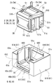
本実施形態のコイル2は、図3に示すように、一対の巻回部2A,2Bと、両巻回部2A,2Bを連結する連結部2Rと、を備える。各巻回部2A,2Bは、巻線2wを螺旋状に巻回した部分で、互いに同一の巻数、同一の巻回方向で中空筒状に形成され、各軸方向が平行になるように並列されている。本例では、一本の巻線2wでコイル2を製造しているが、別々の巻線により作製した巻回部2A,2Bを連結することでコイル2を製造しても構わない。
[コイル]
本実施形態のコイル2は、図3に示すように、一対の巻回部2A,2Bと、両巻回部2A,2Bを連結する連結部2Rと、を備える。各巻回部2A,2Bは、巻線2wを螺旋状に巻回した部分で、互いに同一の巻数、同一の巻回方向で中空筒状に形成され、各軸方向が平行になるように並列されている。本例では、一本の巻線2wでコイル2を製造しているが、別々の巻線により作製した巻回部2A,2Bを連結することでコイル2を製造しても構わない。
本実施形態の各巻回部2A,2Bは角筒状に形成されている。角筒状の巻回部2A,2Bとは、その端面形状が四角形状(正方形状を含む)の角を丸めた形状の巻回部のことである。もちろん、巻回部2A,2Bは円筒状に形成しても構わない。円筒状の巻回部とは、その端面形状が閉曲面形状(楕円形状や真円形状、レーストラック形状など)の巻回部のことである。
巻回部2A,2Bを含むコイル2は、銅やアルミニウム、マグネシウム、あるいはその合金といった導電性材料からなる平角線や丸線などの導体の外周に、絶縁性材料からなる絶縁被覆を備える被覆線によって構成することができる。本実施形態では、導体が銅製の平角線(巻線2w)からなり、絶縁被覆がエナメル(代表的にはポリアミドイミド)からなる被覆平角線をエッジワイズ巻きにすることで、各巻回部2A,2Bを形成している。
コイル2の両端部2a,2bは、巻回部2A,2Bから引き延ばされて、図示しない端子部材に接続される。両端部2a,2bではエナメルなどの絶縁被覆は剥がされている。この端子部材を介して、コイル2に電力供給を行なう電源などの外部装置が接続される。
コイル2の巻回部2A,2Bは、樹脂によって一体化されていることが好ましい。本例の場合、コイル2の巻回部2A,2Bはそれぞれ、一体化樹脂によって個別に一体化されている。本例の一体化樹脂は、巻線2wの外周(エナメルなどの絶縁被覆のさらに外周)に形成される熱融着樹脂の被覆層を融着させることで構成されており、非常に薄い。そのため、巻回部2A,2Bの各ターンが一体化樹脂で一体化されていても、巻回部2A,2Bのターンの形状や、ターンの境界が外観上から分かる状態になっている。一体化樹脂の材質として、例えば、エポキシ樹脂、シリコーン樹脂、不飽和ポリエステルなどの熱硬化性樹脂を利用することもできる。
[磁性コア]
磁性コア3は、図1,2に示すように、巻回部2A,2Bの外側に配置される外側コア部32と、巻回部2A,2Bの内部に配置される内側コア部と、に分けることができる。本例では、外側コア部32と内側コア部とは一体に繋がっている。
磁性コア3は、図1,2に示すように、巻回部2A,2Bの外側に配置される外側コア部32と、巻回部2A,2Bの内部に配置される内側コア部と、に分けることができる。本例では、外側コア部32と内側コア部とは一体に繋がっている。
磁性コア3は、軟磁性粉末と樹脂とを含む複合材料で構成されている。軟磁性粉末は、鉄などの鉄族金属やその合金(Fe-Si合金、Fe-Ni合金など)などで構成される磁性粒子の集合体である。この磁性コア3は、後述するリアクトルの製造方法に示すように、ケース6にコイル2を収納した後、ケース6の内部に複合材料を充填することで形成される。そのため、磁性コア3の外側コア部32は、ケース6の内周面に接合している。
[端面介在部材]
端面介在部材4A,4Bは、図3に示すように、巻回部2A,2Bの端面と外側コア部32(図1,2参照)との間の絶縁を確保する部材である。端面介在部材4A,4Bは、例えば、ポリフェニレンスルフィド(PPS)樹脂、ポリテトラフルオロエチレン(PTFE)樹脂、液晶ポリマー(LCP)、ナイロン6やナイロン66といったポリアミド(PA)樹脂、ポリブチレンテレフタレート(PBT)樹脂、アクリロニトリル・ブタジエン・スチレン(ABS)樹脂などの熱可塑性樹脂で構成することができる。その他、不飽和ポリエステル樹脂、エポキシ樹脂、ウレタン樹脂、シリコーン樹脂などの熱硬化性樹脂などで端面介在部材4A,4Bを形成することができる。上記樹脂にセラミックスフィラーを含有させて、端面介在部材4A,4Bの放熱性を向上させても良い。セラミックスフィラーとしては、例えば、アルミナやシリカなどの非磁性粉末を利用することができる。
端面介在部材4A,4Bは、図3に示すように、巻回部2A,2Bの端面と外側コア部32(図1,2参照)との間の絶縁を確保する部材である。端面介在部材4A,4Bは、例えば、ポリフェニレンスルフィド(PPS)樹脂、ポリテトラフルオロエチレン(PTFE)樹脂、液晶ポリマー(LCP)、ナイロン6やナイロン66といったポリアミド(PA)樹脂、ポリブチレンテレフタレート(PBT)樹脂、アクリロニトリル・ブタジエン・スチレン(ABS)樹脂などの熱可塑性樹脂で構成することができる。その他、不飽和ポリエステル樹脂、エポキシ樹脂、ウレタン樹脂、シリコーン樹脂などの熱硬化性樹脂などで端面介在部材4A,4Bを形成することができる。上記樹脂にセラミックスフィラーを含有させて、端面介在部材4A,4Bの放熱性を向上させても良い。セラミックスフィラーとしては、例えば、アルミナやシリカなどの非磁性粉末を利用することができる。
巻回部2A,2Bの端部2a,2bが配置される側(巻線端部側)にある端面介在部材4Aと、連結部2Rが配置される側(連結部側)にある端面介在部材4Bは、同様の機能を持った構成を備える。図3では、大きさや形状などが若干異なっていても同様の機能を持った構成には同一の符合を付している。
端面介在部材4A,4Bは、矩形枠部40と、巻回部2A,2Bの端面に接触するB字状板材である端面接触部41と、で構成されている。端面介在部材4Bの矩形枠部40の方が、端面介在部材4Aの矩形枠部40よりも、巻回部2A,2Bの軸方向に長くなっている。端面介在部材4Bの矩形枠部40が長くなっているのは、後述するリアクトルの製造方法において、端面介在部材4Bの外側面400(巻回部2A,2Bの並列方向にある面)の位置から複合材料が漏れることを抑制するためである。
端面接触部41のコイル2側の面には、巻回部2A,2Bの軸方向端部を収納する二つのターン収納部41s(特に端面介在部材4Aを参照)が形成されている。ターン収納部41sは、巻回部2A,2Bの軸方向端面の形状に沿った凹みであって、当該端面全体を端面介在部材4A,4Bに面接触させるために形成されている。ターン収納部41sによって巻回部2A,2Bの軸方向端面と端面介在部材4A,4Bとを面接触させることで、接触部分からの樹脂漏れを抑制することができる。
端面接触部41には、貫通孔41hを有する筒状部41cが一対設けられている。筒状部41cは巻回部2A,2Bの内部に挿入される。貫通孔41hは、後述するリアクトルの製造方法において、巻回部2A,2Bの内部に複合材料を充填するための入口となる。また、筒状部41cは、巻回部2A,2Bの内部に挿入され、巻回部2A,2Bに対する端面介在部材4A,4Bの位置を決めると共に、巻回部2A,2Bに充填した複合材料が巻回部2A,2Bの端面から漏れることを抑制する機能を持つ。
端面介在部材4A,4Bは、巻回部2A,2Bの並列方向にある外側面400のうち、巻回部2A,2B側の位置に、巻回部2A,2Bの並列方向の外側に張り出す一対の張出部42を備える。ここで、端面介在部材4Aの張出部42は、張り出し方向の先端に向って一様な厚さに形成されているが、端面介在部材4Bの張出部42は、張り出し方向の先端に向うに従って巻線端部側(紙面左斜め上側)に向って傾斜する先細り形状となっている。端面介在部材4Bの張出部42がこのような形状となっている理由は、後述するリアクトルの製造方法の説明の際に述べる。
≪ケース≫
ケース6は、図3に示すように、底板部60と側壁部61とで構成されている。底板部60と側壁部61とは一体に形成しても良いし、別々に用意した底板部60と側壁部61とを連結しても良い。ケース6の材料としては、例えばアルミニウムやその合金、マグネシウムやその合金などの非磁性金属、あるいは樹脂などを利用することができる。底板部60と側壁部61とを別体とするのであれば、両者60,61の材料を異ならせることもできる。例えば、底板部60を非磁性金属、側壁を樹脂とする、あるいはその逆とすることが挙げられる。
ケース6は、図3に示すように、底板部60と側壁部61とで構成されている。底板部60と側壁部61とは一体に形成しても良いし、別々に用意した底板部60と側壁部61とを連結しても良い。ケース6の材料としては、例えばアルミニウムやその合金、マグネシウムやその合金などの非磁性金属、あるいは樹脂などを利用することができる。底板部60と側壁部61とを別体とするのであれば、両者60,61の材料を異ならせることもできる。例えば、底板部60を非磁性金属、側壁を樹脂とする、あるいはその逆とすることが挙げられる。
[底板部]
本例の底板部60は、巻回部2A,2Bが載置されるコイル載置部60bと、コイル載置部60bよりも高く、外側コア部32(図1,2)の底面に接触するコア接触部60sを備える。コイル載置部60bは、後述する側壁部61の連結部61Cと一体になっており、コア接触部60sは、後述する側壁部61のコア対向部61A,61Bと一体になっている。
本例の底板部60は、巻回部2A,2Bが載置されるコイル載置部60bと、コイル載置部60bよりも高く、外側コア部32(図1,2)の底面に接触するコア接触部60sを備える。コイル載置部60bは、後述する側壁部61の連結部61Cと一体になっており、コア接触部60sは、後述する側壁部61のコア対向部61A,61Bと一体になっている。
[側壁部]
本例の側壁部61は、外側コア部32(図1,2)の外周面に対向する一対のコア対向部61A,61Bと、これらコア対向部61A,61Bを繋ぐ連結部61Cとで構成されている。連結部61Cは、コア対向部61A,61Bを連結して側壁部61の剛性を向上させるためにあり、その高さは、巻回部2A,2Bの下方側の曲げ角部を覆う程度しかない。そのため、図1,2に示すように、巻回部2Aにおける並列方向の外側面、および巻回部2Bにおける並列方向の外側面は、ケース6の外部に露出する。つまり、本例のケース6の側壁部61は、巻回部2A,2Bの並列方向の外側面に対応する部分を切欠くことで形成され、当該外側面をケース6の外方に露出させる切欠き部61Eを備える形状と言い換えることもできる。
本例の側壁部61は、外側コア部32(図1,2)の外周面に対向する一対のコア対向部61A,61Bと、これらコア対向部61A,61Bを繋ぐ連結部61Cとで構成されている。連結部61Cは、コア対向部61A,61Bを連結して側壁部61の剛性を向上させるためにあり、その高さは、巻回部2A,2Bの下方側の曲げ角部を覆う程度しかない。そのため、図1,2に示すように、巻回部2Aにおける並列方向の外側面、および巻回部2Bにおける並列方向の外側面は、ケース6の外部に露出する。つまり、本例のケース6の側壁部61は、巻回部2A,2Bの並列方向の外側面に対応する部分を切欠くことで形成され、当該外側面をケース6の外方に露出させる切欠き部61Eを備える形状と言い換えることもできる。
図3に示すように、コア対向部61A,61Bは、上面視したときに略C字状に形成されている。具体的には、コア対向部61A,61Bは、外側コア部32(図1,2)の端面(コイル2とは反対側の端面)を覆う端面カバー部61eと、外側コア部32の側面を覆う一対のサイドカバー部61sと、がC字状に繋がることで形成されている。サイドカバー部61sの外表面は、巻回部2A,2Bの外側面とほぼ面一になっている。サイドカバー部61sは、コイル2側の縁部近傍の厚みが薄くなることで形成される薄肉部600を備えており、この薄肉部600は、図1,2に示すように、端面介在部材4A,4Bの外側面400を覆う。薄肉部600と外側面400とのオーバーラップ長を長くすることで、後述するリアクトルの製造方法において、端面介在部材4A,4Bと側壁部61のコア対向部61A,61Bとの隙間から複合材料が漏れることを抑制できる。
≪リアクトルの効果≫
本例のリアクトル1では、ケース6の側壁部61のコア対向部61A,61Bによって磁性コア3の外側コア部32を物理的に保護することができる。また、巻回部2A,2Bの外側面を、ケース6の側壁部61から露出させることで、コイル2からケース6の外部に熱が放出され易くなり、リアクトル1の放熱性をより向上させることができる。
本例のリアクトル1では、ケース6の側壁部61のコア対向部61A,61Bによって磁性コア3の外側コア部32を物理的に保護することができる。また、巻回部2A,2Bの外側面を、ケース6の側壁部61から露出させることで、コイル2からケース6の外部に熱が放出され易くなり、リアクトル1の放熱性をより向上させることができる。
≪用途≫
本例のリアクトル1は、ハイブリッド自動車や電気自動車、燃料電池自動車といった電動車両に搭載される双方向DC-DCコンバータなどの電力変換装置の構成部材に利用することができる。
本例のリアクトル1は、ハイブリッド自動車や電気自動車、燃料電池自動車といった電動車両に搭載される双方向DC-DCコンバータなどの電力変換装置の構成部材に利用することができる。
リアクトル1は、液体冷媒に浸漬された状態で使用することができる。液体冷媒は特に限定されないが、ハイブリッド自動車でリアクトル1を利用する場合、ATF(Automatic Transmission Fluid)などを液体冷媒として利用できる。その他、フロリナート(登録商標)などのフッ素系不活性液体、HCFC-123やHFC-134aなどのフロン系冷媒、メタノールやアルコールなどのアルコール系冷媒、アセトンなどのケトン系冷媒などを液体冷媒として利用することもできる。
≪リアクトルの製造方法≫
次に、実施形態1に係るリアクトル1を製造するためのリアクトルの製造方法の一例を説明する。リアクトルの製造方法は、大略、次の工程を備える。リアクトルの製造方法の説明にあたっては主として図3を参照する。
・コイル作製工程
・一体化工程
・ケース準備工程
・配置工程
・充填工程
・硬化工程
次に、実施形態1に係るリアクトル1を製造するためのリアクトルの製造方法の一例を説明する。リアクトルの製造方法は、大略、次の工程を備える。リアクトルの製造方法の説明にあたっては主として図3を参照する。
・コイル作製工程
・一体化工程
・ケース準備工程
・配置工程
・充填工程
・硬化工程
[コイル作製工程]
この工程では、巻線2wを用意し、巻線2wの一部を巻回することでコイル2を作製する。巻線2wの巻回には、公知の巻線機を利用することができる。巻線2wの外周には、巻回部2A,2Bの各ターンを一体化する一体化樹脂となる熱融着樹脂の被覆層を形成することができる。被覆層の厚さは適宜選択することができる。一体化樹脂を設けないのであれば、被覆層を有さない巻線2wを用いれば良く、次の一体化工程も必要ない。
この工程では、巻線2wを用意し、巻線2wの一部を巻回することでコイル2を作製する。巻線2wの巻回には、公知の巻線機を利用することができる。巻線2wの外周には、巻回部2A,2Bの各ターンを一体化する一体化樹脂となる熱融着樹脂の被覆層を形成することができる。被覆層の厚さは適宜選択することができる。一体化樹脂を設けないのであれば、被覆層を有さない巻線2wを用いれば良く、次の一体化工程も必要ない。
[一体化工程]
この工程では、コイル作製工程で作製したコイル2のうち、巻回部2A,2Bを一体化樹脂で一体化する。巻線2wの外周に熱融着樹脂の被覆層を形成している場合、コイル2を熱処理することで、一体化樹脂を形成することができる。これに対して、巻線2wの外周に被覆層を形成していない場合、コイル2の巻回部2A,2Bの外周や内周に樹脂を塗布し、樹脂を硬化させることで一体化樹脂を形成すると良い。
この工程では、コイル作製工程で作製したコイル2のうち、巻回部2A,2Bを一体化樹脂で一体化する。巻線2wの外周に熱融着樹脂の被覆層を形成している場合、コイル2を熱処理することで、一体化樹脂を形成することができる。これに対して、巻線2wの外周に被覆層を形成していない場合、コイル2の巻回部2A,2Bの外周や内周に樹脂を塗布し、樹脂を硬化させることで一体化樹脂を形成すると良い。
[ケース準備工程]
この工程では、コイル2を収納するケース6として、図3に示すように、一方の巻回部2Aの並列方向の外側面および他方の巻回部2Bにおける並列方向の外側面を露出させる切欠き部61Eを設けた側壁部61を備えるケース6を用意する。なお、ケース準備工程は、コイル作製工程や一体化工程の前に行なうこともできる。
この工程では、コイル2を収納するケース6として、図3に示すように、一方の巻回部2Aの並列方向の外側面および他方の巻回部2Bにおける並列方向の外側面を露出させる切欠き部61Eを設けた側壁部61を備えるケース6を用意する。なお、ケース準備工程は、コイル作製工程や一体化工程の前に行なうこともできる。
[配置工程]
この工程では、ケース6の内部にコイル2を配置する。本例では、コイル2に端面介在部材4A,4Bを組み付けた第一組物をケース6の上方からケース6内に挿入する。端面介在部材4A,4Bの外側面400は、コア対向部61A,61Bの薄肉部600で覆われる(図1,2を合わせて参照)。そして、コア対向部61A(61B)の内周面と、端面介在部材4A(4B)との間に空間が形成される。また、一方の切欠き部61Eからは、巻回部2Aの外側面が露出し、他方の切欠き部61Eからは、巻回部2Bの外側面が露出する。ここで、コイル載置部60bと第一組物との間に図示しない放熱材を配置しても良い。放熱材としては、例えば放熱グリスや、発泡性の放熱シートなどを利用することができる。
この工程では、ケース6の内部にコイル2を配置する。本例では、コイル2に端面介在部材4A,4Bを組み付けた第一組物をケース6の上方からケース6内に挿入する。端面介在部材4A,4Bの外側面400は、コア対向部61A,61Bの薄肉部600で覆われる(図1,2を合わせて参照)。そして、コア対向部61A(61B)の内周面と、端面介在部材4A(4B)との間に空間が形成される。また、一方の切欠き部61Eからは、巻回部2Aの外側面が露出し、他方の切欠き部61Eからは、巻回部2Bの外側面が露出する。ここで、コイル載置部60bと第一組物との間に図示しない放熱材を配置しても良い。放熱材としては、例えば放熱グリスや、発泡性の放熱シートなどを利用することができる。
[充填工程]
充填工程では、コア対向部61A(61B)の内周面と、端面介在部材4A(4B)との間に形成される空間の上方から複合材料を充填する。ケース6内に充填された複合材料は、コア対向部61A(61B)と端面介在部材4A(4B)との間に溜まると共に、端面介在部材4A,4Bの貫通孔41hから巻回部2A,2Bの内部にも流れ込む。コア対向部61A(61B)の薄肉部600が端面介在部材4A(4B)の外側面400を覆っているため、端面介在部材4A(4B)の外側面400の位置からケース6の外側に複合材料が漏れることが抑制される。
充填工程では、コア対向部61A(61B)の内周面と、端面介在部材4A(4B)との間に形成される空間の上方から複合材料を充填する。ケース6内に充填された複合材料は、コア対向部61A(61B)と端面介在部材4A(4B)との間に溜まると共に、端面介在部材4A,4Bの貫通孔41hから巻回部2A,2Bの内部にも流れ込む。コア対向部61A(61B)の薄肉部600が端面介在部材4A(4B)の外側面400を覆っているため、端面介在部材4A(4B)の外側面400の位置からケース6の外側に複合材料が漏れることが抑制される。
複合材料の充填の際は、端面介在部材4Bの張出部42のテーパー面と、ケース6のコア対向部61Bのサイドカバー部61sの縁部と、の間に治具を挿入し、端面介在部材4Bを巻線端部側に押圧する。ここで、端面介在部材4Bの矩形枠部40が長めに形成されているため、端面介在部材4Bが巻線端部側に押圧されても、外側面400と薄肉部600とのオーバーラップ長は十分に確保される。この端面介在部材4Bを巻線端部側に押圧することで、複合材料の充填圧力によってケース6内でコイル2が動くことを抑制でき、ケース6から複合材料が漏れることを抑制できる。また、端面介在部材4Bを巻線端部側に押圧することで、ケース6に対するコイル2の端部2a,2bの位置が正確に決まるので、リアクトル1を車両内の所定位置に配置したときに、リアクトル1を他の部材に接続し易くなる。
[硬化工程]
硬化工程では、熱処理などで複合材料を硬化させる。硬化した複合材料のうち、巻回部2A,2Bの内部にあるものは内側コア部となり、巻回部2A,2Bの外側にあるものは外側コア部32となる。
硬化工程では、熱処理などで複合材料を硬化させる。硬化した複合材料のうち、巻回部2A,2Bの内部にあるものは内側コア部となり、巻回部2A,2Bの外側にあるものは外側コア部32となる。
<実施形態2>
実施形態2では、巻回部の一方のみがケース6から露出したリアクトル1を図4~図6に基づいて説明する。実施形態1と同様の機能を有する構成には、実施形態1と同一の符号を付して、その説明を省略する。
実施形態2では、巻回部の一方のみがケース6から露出したリアクトル1を図4~図6に基づいて説明する。実施形態1と同様の機能を有する構成には、実施形態1と同一の符号を付して、その説明を省略する。
≪ケース≫
実施形態2のケース6は、実施形態1のケース6とは側壁部61の構成が異なる。本例のケース6の側壁部61は、コア対向部61A,61Bと、巻回部2B側の連結部61Cに加えて、コイル対向部61Dを備える。コイル対向部61Dは、巻回部2Aの外側面に対向する部材である。つまり、本例のケース6の側壁部61は、組合体10の外周面のうち、巻回部2Bの外側面を除く三方を囲むように構成されており、切欠き部61Eの位置で巻回部2Bの外側面がケース6の外部に露出している。もちろん、巻回部2Aの外側面がケース6の外部に露出するように、コイル対向部61Dを巻回部2B側に設けることもできる。
実施形態2のケース6は、実施形態1のケース6とは側壁部61の構成が異なる。本例のケース6の側壁部61は、コア対向部61A,61Bと、巻回部2B側の連結部61Cに加えて、コイル対向部61Dを備える。コイル対向部61Dは、巻回部2Aの外側面に対向する部材である。つまり、本例のケース6の側壁部61は、組合体10の外周面のうち、巻回部2Bの外側面を除く三方を囲むように構成されており、切欠き部61Eの位置で巻回部2Bの外側面がケース6の外部に露出している。もちろん、巻回部2Aの外側面がケース6の外部に露出するように、コイル対向部61Dを巻回部2B側に設けることもできる。
≪コイル≫
本例のリアクトル1は、端面介在部材の代わりに、コイル2にコイルモールド部5を設けた点でも実施形態1と異なる。コイルモールド部5は、絶縁性樹脂で構成されており、例えば実施形態1の端面介在部材を構成する材料と同様の材料を利用することができる。コイルモールド部5には、端面介在部材と同様に、フィラーが含有されていても良い。
本例のリアクトル1は、端面介在部材の代わりに、コイル2にコイルモールド部5を設けた点でも実施形態1と異なる。コイルモールド部5は、絶縁性樹脂で構成されており、例えば実施形態1の端面介在部材を構成する材料と同様の材料を利用することができる。コイルモールド部5には、端面介在部材と同様に、フィラーが含有されていても良い。
コイルモールド部5は、巻回部2A,2Bの各ターンを一体化するターン被覆部50と、巻回部2A,2Bの端面と外側コア部32との間に介在される端面被覆部51とを備える。さらに、コイルモールド部5は、巻回部2A,2Bの連結部(図示せず)を覆う連結部被覆部52を備える。
角筒状のコイル2の巻回部2A,2Bは、巻線2wが曲げられることで形成される四つの角部と、巻線2wが曲げられていない平坦部と、に分けられる。本例のターン被覆部50は、巻回部2A,2Bの四つの角部を覆うことで、巻回部2A,2Bの各ターンを一体化している。ターン被覆部50は、巻回部2A,2Bの平坦部を覆っていないため、巻回部2A,2Bの外側面からの放熱が、ターン被覆部50によって阻害されることはない。
端面被覆部51は、図6に示すように、巻回部2Aのターン被覆部50と巻回部2Bのターン被覆部50を連結するように設けられる。端面被覆部51には、巻回部2A,2Bの内部に連通する一対の貫通孔51h,51hが設けられている。この貫通孔51hは、実施形態1の端面介在部材4A,4Bの貫通孔41hと同様の機能、即ちリアクトルの製造の際に巻回部2A,2Bの内部に複合材料を導く機能を持っている。
端面被覆部51は、巻回部2A,2Bの軸方向にコイル2から離れる側に向って突出する枠状に形成されている。その枠状の端面被覆部51の外側面(巻回部2A,2Bの並列方向の面)510は、ケース6のコア対向部61A,61Bの薄肉部600に当接する。外側面510は、実施形態1の端面介在部材4A,4Bの外側面400と同様の機能、即ちケース6におけるコイル2の位置決め、およびリアクトル1の作製時の複合材料の漏れを抑制する機能を持っている。
端面被覆部51はさらに、一対の貫通孔51h,51hの間に設けられるギャップ部51gを備える。ギャップ部51gは、巻回部2A,2Bの軸方向におけるコイル2から離れる側に向って突出する板状部材である。ギャップ部51gは、図4,5に示すように、巻回部2A,2Bの並列方向に外側コア部32を分断し、外側コア部32の位置にギャップを形成する。ギャップ部51gの厚さを調整することで、磁性コア3の磁気特性を調整することができる。ここで、ギャップ部51gは、外側コア部32を物理的に完全に2分割するものに限定されるわけではなく、外側コア部32の磁路を分断できる構成であれば良い。つまり、外側コア部32における磁路に影響の無いところには、ギャップ部51gは無くても構わない。例えば、ギャップ部51gは、巻回部2A,2Bの軸方向における外側コア部32の端面に到達しない長さであっても、磁路となる部分にギャップ部51gが介在されていれば良い。
≪リアクトルの効果≫
実施形態2の構成とすることで、リアクトル1の放熱性を向上させつつ、コイル2の両側面が露出される構成よりもリアクトル1の設置の自由度を高めることができる。ケース6の側壁部61がコイル対向部61Dを備える構成では、底板部60やコア対向部61A,61Bだけでなく、コイル対向部61Dも設置対象への取付部とすることができるからである。
実施形態2の構成とすることで、リアクトル1の放熱性を向上させつつ、コイル2の両側面が露出される構成よりもリアクトル1の設置の自由度を高めることができる。ケース6の側壁部61がコイル対向部61Dを備える構成では、底板部60やコア対向部61A,61Bだけでなく、コイル対向部61Dも設置対象への取付部とすることができるからである。
≪リアクトルの製造方法≫
実施形態2のリアクトル1を製造するには、図6に示すように、コイルモールド部5を有するコイル2とケース6とを用意する。そして、ケース6の内部にコイル2を挿入する(配置工程)。その際、コイル対向部61Dの内周面に放熱材7を配置すると共に、コイル載置部60bにも放熱材70を配置すると良い。放熱材7,70を設けることで、コイル2からケース6への放熱を促すことができる。放熱材7,70としては、例えば放熱グリスや、発泡性の放熱シートなどを利用することができる。
実施形態2のリアクトル1を製造するには、図6に示すように、コイルモールド部5を有するコイル2とケース6とを用意する。そして、ケース6の内部にコイル2を挿入する(配置工程)。その際、コイル対向部61Dの内周面に放熱材7を配置すると共に、コイル載置部60bにも放熱材70を配置すると良い。放熱材7,70を設けることで、コイル2からケース6への放熱を促すことができる。放熱材7,70としては、例えば放熱グリスや、発泡性の放熱シートなどを利用することができる。
ケース6にコイル2を挿入することで、コア対向部61A(61B)の内周面と、端面被覆部51との間に空間が形成される。この空間の上方から複合材料を充填する(充填工程)。当該空間からケース6内に充填された複合材料は、コア対向部61A(61B)と端面被覆部51との間に溜まって外側コア部32(図4,5)を形成すると共に、貫通孔51hを介して巻回部2A,2Bの内部に流れ込んで内側コア部を形成する。ここで、コア対向部61A(61B)の薄肉部600が端面被覆部51の外側面510を覆っているため、端面被覆部51の外側面510の位置からケース6の外側に複合材料が漏れることが抑制される。
<実施形態3>
実施形態1,2に示すように、本開示の磁性コア3は、ケース6内に複合材料を充填することで構成されている。つまり、磁性コア3の外側コア部32が側壁部61の内周面(コア対向部61A,61Bの内周面)に接合することで、ケース6からの組合体10の脱落が抑制されている。ケース6からの組合体10の脱落をより効果的に抑制するために、ケース6に抜け止めとなる構成を設けることが好ましい。その抜け止めとなる構成の具体例を図7に基づいて説明する。
実施形態1,2に示すように、本開示の磁性コア3は、ケース6内に複合材料を充填することで構成されている。つまり、磁性コア3の外側コア部32が側壁部61の内周面(コア対向部61A,61Bの内周面)に接合することで、ケース6からの組合体10の脱落が抑制されている。ケース6からの組合体10の脱落をより効果的に抑制するために、ケース6に抜け止めとなる構成を設けることが好ましい。その抜け止めとなる構成の具体例を図7に基づいて説明する。
図7は、実施形態3で使用するケース6の概略斜視図である。図7のケース6は、実施形態1の図3のケース6と殆ど同じであるが、コア対向部61Aの内周面に抜け止め凹部61dを備える点で、実施形態1のケース6と異なる。なお、図面上は見えない位置にあるが、コア対向部61Bの内周面にもコア対向部61Aと同様の抜け止め凹部61dが設けられている。
抜け止め凹部61dは、コア対向部61Aの端面カバー部61eの内周面のうち、底板部60側の一部が外側コア部32(図1参照)から離れる側に凹むことで形成される。このような抜け止め凹部61dを有するケース6の内部に複合材料を充填すれば、抜け止め凹部61dに外側コア部32の一部が入り込み、外側コア部32が抜け止め凹部61dに引っ掛かる。この引っ掛かりによって、ケース6からの組合体10の脱落を抑制することができる。
図7とは異なり、抜け止め凹部61dは、サイドカバー部61sの位置に設けることもできる。また、抜け止め凹部61dは、実施形態2のケース6にも適用することができる。
1 リアクトル
10 組合体
2 コイル 2w 巻線
2A,2B 巻回部 2R 連結部 2a,2b 端部
3 磁性コア 32 外側コア部
4A,4B 端面介在部材
40 矩形枠部 41 端面接触部 42 張出部 400 外側面
41c 筒状部 41h 貫通孔 41s ターン収納部
5 コイルモールド部
50 ターン被覆部 51 端面被覆部 52 連結部被覆部
51g ギャップ部 51h 貫通孔 510 外側面
6 ケース 60 底板部 61 側壁部
61A,61B コア対向部 61C 連結部 61D コイル対向部
61E 切欠き部
60b コイル載置部 60s コア接触部 600 薄肉部
61d 抜け止め凹部 61e 端面カバー部 61s サイドカバー部
7,70 放熱材
10 組合体
2 コイル 2w 巻線
2A,2B 巻回部 2R 連結部 2a,2b 端部
3 磁性コア 32 外側コア部
4A,4B 端面介在部材
40 矩形枠部 41 端面接触部 42 張出部 400 外側面
41c 筒状部 41h 貫通孔 41s ターン収納部
5 コイルモールド部
50 ターン被覆部 51 端面被覆部 52 連結部被覆部
51g ギャップ部 51h 貫通孔 510 外側面
6 ケース 60 底板部 61 側壁部
61A,61B コア対向部 61C 連結部 61D コイル対向部
61E 切欠き部
60b コイル載置部 60s コア接触部 600 薄肉部
61d 抜け止め凹部 61e 端面カバー部 61s サイドカバー部
7,70 放熱材
Claims (10)
- 並列された一対の巻回部を有するコイルと、
前記巻回部の内部に配置される内側コア部、および前記巻回部から露出する外側コア部を有する磁性コアと、
前記コイルと前記磁性コアの組合体を収納するケースと、を備えるリアクトルであって、
前記ケースは、前記組合体を載置する底板部と、前記外側コア部の外周面に対向する部分を有する側壁部とを備え、
前記磁性コアは、軟磁性粉末と樹脂とを含む複合材料で構成され、前記外側コア部の位置で前記底板部の上面と前記側壁部の内周面に接合しており、
前記側壁部は、前記巻回部が並列される方向を並列方向としたとき、一方の前記巻回部における前記並列方向の外側面、および他方の前記巻回部における前記並列方向の外側面の少なくとも一方を前記ケースの外方に露出させる切欠き部を備えるリアクトル。 - 前記側壁部は、
前記外側コア部の外周面に対向する一対のコア対向部と、
一方の前記巻回部の前記外側面を前記ケースの外方に露出させる一方の前記切欠き部と、
他方の前記巻回部の前記外側面を前記ケースの外方に露出させる他方の前記切欠き部と、を備える請求項1に記載のリアクトル。 - 前記側壁部は、
前記外側コア部の外周面に対向する一対のコア対向部と、
一対の前記コア対向部を繋ぎ、一方の前記巻回部の前記外側面、または他方の前記巻回部の前記外側面に対向するコイル対向部と、
前記コイル対向部で覆われる前記巻回部とは反対側の前記巻回部の前記外側面を前記ケースの外方に露出させる前記切欠き部と、を備え、
前記コイル対向部と前記巻回部との間に介在される放熱材を備える請求項1に記載のリアクトル。 - 前記巻回部の端面と前記外側コア部との間に介在される一対の端面介在部材を備え、
前記端面介在部材における前記並列方向にある外側面の少なくとも一部に、前記側壁部の内周面が当接する請求項1から請求項3のいずれか1項に記載のリアクトル。 - 前記端面介在部材は、前記巻回部の並列方向にある外側面のうち、前記巻回部側の位置に、前記並列方向の外側に張り出す張出部を備え、
前記巻回部を構成する巻線の端部が配置される側を巻線端部側、一対の前記巻回部を連結する連結部が配置される側を連結部側としたとき、前記連結部側の前記端面介在部材に備わる前記張出部は、前記張出部の張り出し方向の先端に向うに従って前記巻線端部側に向って傾斜する先細り形状となっている請求項4に記載のリアクトル。 - 前記コイルは、絶縁性樹脂で構成されるコイルモールド部を備え、
前記コイルモールド部は、
前記巻回部の各ターンを一体化するターン被覆部と、
前記巻回部の端面と前記外側コア部との間に介在される端面被覆部と、を備える請求項1から請求項3のいずれか1項に記載のリアクトル。 - 前記側壁部は、前記外側コア部の外周面に対向する一対のコア対向部を備え、
前記コア対向部は、その内周面における前記底板部側の一部が前記外側コア部から離れる側に凹むことで形成される抜け止め凹部を備え、
前記外側コア部の一部が前記抜け止め凹部に入り込んでいる請求項1から請求項6のいずれか1項に記載のリアクトル。 - 前記外側コア部にギャップ部を備える請求項1から請求項7のいずれか1項に記載のリアクトル。
- 並列された一対の巻回部を有するコイルと、前記巻回部の内部に配置される内側コア部、および前記巻回部から露出する外側コア部を有する磁性コアと、の組合体をケースに収納させるリアクトルの製造方法であって、
前記巻回部が並列される方向を並列方向としたとき、前記コイルを収納する前記ケースとして、一方の前記巻回部における前記並列方向の外側面および他方の前記巻回部における前記並列方向の外側面の少なくとも一方を露出させる切欠き部を設けた側壁部を備えるケースを用意するケース準備工程と、
前記コイルを前記ケースの内部に収納する配置工程と、
前記コイルの前記巻回部の端面と前記ケースとの間に、軟磁性粉末と樹脂を含む複合材料を充填し、前記複合材料で構成される前記磁性コアを形成する充填工程と、
を備えるリアクトルの製造方法。 - 前記配置工程では、前記コイルの端面に端面介在部材を当接させた状態で、前記コイルを前記ケースに収納し、前記ケースに備わる前記切欠き部の縁部を前記端面介在部材で封止する請求項9に記載のリアクトルの製造方法。
Priority Applications (2)
| Application Number | Priority Date | Filing Date | Title |
|---|---|---|---|
| CN201780041835.3A CN109416976B (zh) | 2016-07-22 | 2017-07-07 | 电抗器及电抗器的制造方法 |
| US16/318,833 US20190267184A1 (en) | 2016-07-22 | 2017-07-07 | Reactor and method for producing reactor |
Applications Claiming Priority (2)
| Application Number | Priority Date | Filing Date | Title |
|---|---|---|---|
| JP2016-144591 | 2016-07-22 | ||
| JP2016144591A JP6635305B2 (ja) | 2016-07-22 | 2016-07-22 | リアクトル、およびリアクトルの製造方法 |
Publications (1)
| Publication Number | Publication Date |
|---|---|
| WO2018016352A1 true WO2018016352A1 (ja) | 2018-01-25 |
Family
ID=60993078
Family Applications (1)
| Application Number | Title | Priority Date | Filing Date |
|---|---|---|---|
| PCT/JP2017/024972 Ceased WO2018016352A1 (ja) | 2016-07-22 | 2017-07-07 | リアクトル、およびリアクトルの製造方法 |
Country Status (4)
| Country | Link |
|---|---|
| US (1) | US20190267184A1 (ja) |
| JP (1) | JP6635305B2 (ja) |
| CN (1) | CN109416976B (ja) |
| WO (1) | WO2018016352A1 (ja) |
Families Citing this family (4)
| Publication number | Priority date | Publication date | Assignee | Title |
|---|---|---|---|---|
| US11532419B2 (en) * | 2018-12-21 | 2022-12-20 | Sumida Corporation | Coil component |
| JP7180390B2 (ja) * | 2019-01-10 | 2022-11-30 | 株式会社オートネットワーク技術研究所 | リアクトル |
| EP4036940A1 (en) * | 2021-02-02 | 2022-08-03 | Schaffner EMV AG | Magnetic component |
| JP7691905B2 (ja) * | 2021-10-20 | 2025-06-12 | Tdk株式会社 | コイル装置 |
Citations (6)
| Publication number | Priority date | Publication date | Assignee | Title |
|---|---|---|---|---|
| JP2010226138A (ja) * | 2008-08-22 | 2010-10-07 | Sumitomo Electric Ind Ltd | リアクトル用部品およびリアクトル |
| JP2011124242A (ja) * | 2008-04-08 | 2011-06-23 | Hitachi Metals Ltd | リアクトル装置 |
| JP2011210791A (ja) * | 2010-03-29 | 2011-10-20 | Denso Corp | リアクトル及びその製造方法 |
| JP2014075596A (ja) * | 2013-11-25 | 2014-04-24 | Sumitomo Electric Ind Ltd | リアクトル |
| JP2015012147A (ja) * | 2013-06-28 | 2015-01-19 | 株式会社オートネットワーク技術研究所 | リアクトル |
| JP2015095563A (ja) * | 2013-11-12 | 2015-05-18 | 株式会社タムラ製作所 | リアクトル |
Family Cites Families (5)
| Publication number | Priority date | Publication date | Assignee | Title |
|---|---|---|---|---|
| JPH0696965A (ja) * | 1992-09-14 | 1994-04-08 | Matsushita Electric Ind Co Ltd | トランス |
| JP2007027185A (ja) * | 2005-07-12 | 2007-02-01 | Denso Corp | コイル封止型樹脂成形リアクトル及びその製造方法 |
| WO2011089941A1 (ja) * | 2010-01-20 | 2011-07-28 | 住友電気工業株式会社 | リアクトル |
| JP2015076443A (ja) * | 2013-10-07 | 2015-04-20 | 株式会社デンソー | リアクトル及びリアクトル放熱構造 |
| JP6331495B2 (ja) * | 2014-03-06 | 2018-05-30 | 株式会社デンソー | リアクトル |
-
2016
- 2016-07-22 JP JP2016144591A patent/JP6635305B2/ja active Active
-
2017
- 2017-07-07 US US16/318,833 patent/US20190267184A1/en not_active Abandoned
- 2017-07-07 CN CN201780041835.3A patent/CN109416976B/zh active Active
- 2017-07-07 WO PCT/JP2017/024972 patent/WO2018016352A1/ja not_active Ceased
Patent Citations (6)
| Publication number | Priority date | Publication date | Assignee | Title |
|---|---|---|---|---|
| JP2011124242A (ja) * | 2008-04-08 | 2011-06-23 | Hitachi Metals Ltd | リアクトル装置 |
| JP2010226138A (ja) * | 2008-08-22 | 2010-10-07 | Sumitomo Electric Ind Ltd | リアクトル用部品およびリアクトル |
| JP2011210791A (ja) * | 2010-03-29 | 2011-10-20 | Denso Corp | リアクトル及びその製造方法 |
| JP2015012147A (ja) * | 2013-06-28 | 2015-01-19 | 株式会社オートネットワーク技術研究所 | リアクトル |
| JP2015095563A (ja) * | 2013-11-12 | 2015-05-18 | 株式会社タムラ製作所 | リアクトル |
| JP2014075596A (ja) * | 2013-11-25 | 2014-04-24 | Sumitomo Electric Ind Ltd | リアクトル |
Also Published As
| Publication number | Publication date |
|---|---|
| JP6635305B2 (ja) | 2020-01-22 |
| CN109416976A (zh) | 2019-03-01 |
| US20190267184A1 (en) | 2019-08-29 |
| JP2018014459A (ja) | 2018-01-25 |
| CN109416976B (zh) | 2020-10-16 |
Similar Documents
| Publication | Publication Date | Title |
|---|---|---|
| JP6358565B2 (ja) | リアクトル、およびリアクトルの製造方法 | |
| US10910147B2 (en) | Reactor and method for manufacturing reactor | |
| WO2016167199A1 (ja) | リアクトル | |
| WO2018016352A1 (ja) | リアクトル、およびリアクトルの製造方法 | |
| CN112017853A (zh) | 电抗器 | |
| WO2018159503A1 (ja) | リアクトル | |
| JP7215036B2 (ja) | リアクトル | |
| WO2020085053A1 (ja) | リアクトル | |
| JP6512188B2 (ja) | リアクトル | |
| US20200312542A1 (en) | Reactor and method for manufacturing reactor | |
| CN110828130A (zh) | 电抗器 | |
| US11017935B2 (en) | Reactor | |
| WO2019168152A1 (ja) | リアクトル、及びリアクトルの製造方法 | |
| CN111788646B (zh) | 电抗器 | |
| JP2015220449A (ja) | リアクトル | |
| JP6362030B2 (ja) | リアクトル | |
| JP6508622B2 (ja) | リアクトル、およびリアクトルの製造方法 | |
| CN111344822B (zh) | 电抗器 | |
| US12009130B2 (en) | Reactor | |
| JP7022344B2 (ja) | リアクトル |
Legal Events
| Date | Code | Title | Description |
|---|---|---|---|
| 121 | Ep: the epo has been informed by wipo that ep was designated in this application |
Ref document number: 17830872 Country of ref document: EP Kind code of ref document: A1 |
|
| NENP | Non-entry into the national phase |
Ref country code: DE |
|
| 122 | Ep: pct application non-entry in european phase |
Ref document number: 17830872 Country of ref document: EP Kind code of ref document: A1 |