WO2018016545A1 - 回転電機および非接触発電機 - Google Patents
回転電機および非接触発電機 Download PDFInfo
- Publication number
- WO2018016545A1 WO2018016545A1 PCT/JP2017/026167 JP2017026167W WO2018016545A1 WO 2018016545 A1 WO2018016545 A1 WO 2018016545A1 JP 2017026167 W JP2017026167 W JP 2017026167W WO 2018016545 A1 WO2018016545 A1 WO 2018016545A1
- Authority
- WO
- WIPO (PCT)
- Prior art keywords
- permanent magnet
- cogging torque
- moving body
- rotating body
- rotating
- Prior art date
- Legal status (The legal status is an assumption and is not a legal conclusion. Google has not performed a legal analysis and makes no representation as to the accuracy of the status listed.)
- Ceased
Links
Images



Classifications
-
- H—ELECTRICITY
- H02—GENERATION; CONVERSION OR DISTRIBUTION OF ELECTRIC POWER
- H02K—DYNAMO-ELECTRIC MACHINES
- H02K7/00—Arrangements for handling mechanical energy structurally associated with dynamo-electric machines, e.g. structural association with mechanical driving motors or auxiliary dynamo-electric machines
- H02K7/10—Structural association with clutches, brakes, gears, pulleys or mechanical starters
- H02K7/104—Structural association with clutches, brakes, gears, pulleys or mechanical starters with eddy-current brakes
-
- H—ELECTRICITY
- H02—GENERATION; CONVERSION OR DISTRIBUTION OF ELECTRIC POWER
- H02K—DYNAMO-ELECTRIC MACHINES
- H02K49/00—Dynamo-electric clutches; Dynamo-electric brakes
- H02K49/02—Dynamo-electric clutches; Dynamo-electric brakes of the asynchronous induction type
- H02K49/04—Dynamo-electric clutches; Dynamo-electric brakes of the asynchronous induction type of the eddy-current hysteresis type
- H02K49/046—Dynamo-electric clutches; Dynamo-electric brakes of the asynchronous induction type of the eddy-current hysteresis type with an axial airgap
-
- H—ELECTRICITY
- H02—GENERATION; CONVERSION OR DISTRIBUTION OF ELECTRIC POWER
- H02K—DYNAMO-ELECTRIC MACHINES
- H02K7/00—Arrangements for handling mechanical energy structurally associated with dynamo-electric machines, e.g. structural association with mechanical driving motors or auxiliary dynamo-electric machines
- H02K7/18—Structural association of electric generators with mechanical driving motors, e.g. with turbines
- H02K7/1807—Rotary generators
- H02K7/1846—Rotary generators structurally associated with wheels or associated parts
-
- B—PERFORMING OPERATIONS; TRANSPORTING
- B62—LAND VEHICLES FOR TRAVELLING OTHERWISE THAN ON RAILS
- B62J—CYCLE SADDLES OR SEATS; AUXILIARY DEVICES OR ACCESSORIES SPECIALLY ADAPTED TO CYCLES AND NOT OTHERWISE PROVIDED FOR, e.g. ARTICLE CARRIERS OR CYCLE PROTECTORS
- B62J6/00—Arrangement of optical signalling or lighting devices on cycles; Mounting or supporting thereof; Circuits therefor
- B62J6/06—Arrangement of lighting dynamos or drives therefor
-
- H—ELECTRICITY
- H02—GENERATION; CONVERSION OR DISTRIBUTION OF ELECTRIC POWER
- H02K—DYNAMO-ELECTRIC MACHINES
- H02K21/00—Synchronous motors having permanent magnets; Synchronous generators having permanent magnets
- H02K21/12—Synchronous motors having permanent magnets; Synchronous generators having permanent magnets with stationary armatures and rotating magnets
- H02K21/14—Synchronous motors having permanent magnets; Synchronous generators having permanent magnets with stationary armatures and rotating magnets with magnets rotating within the armatures
-
- H—ELECTRICITY
- H02—GENERATION; CONVERSION OR DISTRIBUTION OF ELECTRIC POWER
- H02K—DYNAMO-ELECTRIC MACHINES
- H02K2201/00—Specific aspects not provided for in the other groups of this subclass relating to the magnetic circuits
- H02K2201/03—Machines characterised by aspects of the air-gap between rotor and stator
Definitions
- the present invention relates to a rotating electrical machine that rotates in a non-contact manner and a non-contact generator that generates power in a non-contact manner.
- US Patent Publication No. 2014/0132155 discloses a dynamo for a bicycle that generates power without contact.
- the outer peripheral surface of an annular permanent magnet that rotates around a rotation axis extending in a direction orthogonal to the rotation axis of the bicycle wheel is separated from one side surface that is continuous with the outer peripheral surface of the wheel. It is arranged.
- a permanent magnet has a plurality of magnetic poles arranged in the circumferential direction, and the magnetization directions of the adjacent magnetic poles are reversed. For example, when the wheel rotates with the N pole of the permanent magnet opposed to one side of the wheel, an eddy current is generated on one side of the wheel in a direction that prevents a change in magnetic flux from the permanent magnet.
- the permanent magnet rotates in the rotation direction of the wheel by the repulsive force and the attractive force of the magnetic flux caused by the eddy current and the magnetic flux from the permanent magnet.
- the induction power can be taken out from the coil.
- a single-phase coil is wound around a permanent magnet.
- a single-phase coil cannot effectively use the magnetic flux of a portion of the permanent magnet where the coil is not wound. Can not be increased.
- the direction of the polarity of the permanent magnet around the coil is symmetric about the rotation axis, the total amount of magnetic flux that interlinks the coil always cancels out. .
- the present invention has been made in view of the above-described problems, and an object of the present invention is to provide a rotating electrical machine and a non-contact power generator that have good magnetic efficiency, little leakage of magnetic flux, and have taken measures against cogging torque. It is.
- the moving body which is a rotating or moving conductor, is disposed oppositely on one main surface of the moving body, and is generated according to the rotation or moving direction of the moving body.
- a first rotating body having a first permanent magnet that rotates about a predetermined rotation axis by a Lorentz force
- a rotating electrical machine including a cogging torque canceling unit that reduces or cancels a cogging torque generated in the first permanent magnet by a relative shape and positional relationship between the moving body and the first permanent magnet.
- a first permanent that is arranged oppositely on one main surface of a rotating or moving moving body and rotates about a predetermined rotation axis according to the rotation or moving direction of the moving body.
- a first rotating body having a magnet;
- a cogging torque canceling unit that reduces or cancels the cogging torque generated in the first permanent magnet due to the relative shape and positional relationship between the moving body and the first permanent magnet;
- the first rotating body has a repulsive force and an attractive force acting on the first permanent magnet based on an eddy current generated in a direction that prevents a change in magnetic flux from the first permanent magnet on the one main surface of the moving body.
- a rotating electrical machine is provided in which the surface speed of the one side surface of the first rotating body arranged to face the moving body is slower than the surface speed of the one main surface of the moving body arranged to face the first rotating body.
- the cogging torque canceling unit may generate a cogging torque having a phase opposite to that of the cogging torque generated in the first permanent magnet according to a relative shape and positional relationship between the moving body and the first permanent magnet.
- the cogging torque canceling unit may reduce or cancel the cogging torque using a second permanent magnet different from the first permanent magnet or a magnetic material.
- the cogging torque canceling unit is A second rotating body having a second permanent magnet different from the first permanent magnet and rotating in synchronization with the first rotating body; A first magnetic body that is magnetically coupled to the second permanent magnet.
- the cogging torque canceling unit may reduce the cogging torque by adjusting a gap between the second rotating body and the first magnetic body.
- the second rotating body may be an annular member that rotates around the rotation axis together with the first permanent magnet,
- the first magnetic body may be disposed on an inner peripheral side of the annular member, and the cogging torque may be reduced by adjusting a gap with the inner peripheral surface of the annular member.
- a coil may be provided that is arranged at a position where the magnetic flux from the second permanent magnet is linked and generates an induced current corresponding to the amount of change in the linked magnetic flux.
- the cogging torque canceling unit may include a second magnetic body that is magnetically coupled to the first permanent magnet, The cogging torque canceling unit may reduce the cogging torque by adjusting a region where the first permanent magnet and the second magnetic body overlap each other.
- the second magnetic body may be a yoke.
- the cogging torque canceling unit is A second rotating body having a second permanent magnet that is disposed oppositely on one main surface of the moving body and rotates around a predetermined rotation axis according to the rotation or moving direction of the moving body; A synchronous rotating mechanism that rotates the first rotating body and the second rotating body in synchronization with each other; The cogging torque may be reduced by making the magnetic pole of the second permanent magnet overlapping the moving body different from the magnetic pole of the first permanent magnet overlapping the moving body.
- a rotating body that is a rotating or moving conductor is disposed on one main surface of the moving body so as to be separated from the main surface, and a predetermined rotation is generated by a Lorentz force generated according to the rotation or moving direction of the moving body.
- a first rotating body having a first permanent magnet rotating about an axis;
- a power generation unit that converts kinetic energy generated by the rotation of the first rotating body into electrical energy,
- the non-contact power generator includes a cogging torque canceling unit that reduces or cancels cogging torque generated in the first permanent magnet according to a relative shape and positional relationship between the moving body and the first permanent magnet.
- a first permanent that is arranged oppositely on one main surface of a rotating or moving moving body and rotates about a predetermined rotation axis according to the rotation or moving direction of the moving body.
- a first rotating body having a magnet;
- a power generation unit that converts kinetic energy generated by the rotation of the first rotating body into electrical energy,
- the power generation unit includes a cogging torque canceling unit that reduces or cancels the cogging torque generated in the first permanent magnet due to the relative shape and positional relationship between the moving body and the first permanent magnet,
- the first rotating body has a repulsive force and an attractive force acting on the first permanent magnet based on an eddy current generated in a direction that prevents a change in magnetic flux from the first permanent magnet on the one main surface of the moving body.
- a non-contact power generator is provided in which a surface speed of the one side surface of the first rotating body arranged to face the moving body is slower than a surface speed of the one main surface of the moving body arranged to face the first rotating body.
- the cogging torque canceling unit may reduce or cancel the cogging torque by using a second permanent magnet included in the power generation unit separately from the first permanent magnet.
- the cogging torque canceling unit is A second rotating body having a second permanent magnet different from the first permanent magnet and rotating in synchronization with the first rotating body; A first magnetic body magnetically coupled to the second permanent magnet,
- the power generation unit may include a coil that is arranged at a position where the magnetic flux from the second permanent magnet is linked and generates an induced current according to a change amount of the linked magnetic flux.
- the cogging torque canceling unit has a second magnetic body magnetically coupled to the first permanent magnet,
- the cogging torque canceling unit may reduce the cogging torque by adjusting a region where the first permanent magnet and the second magnetic body overlap each other.
- the cogging torque canceling unit is A second rotating body having a second permanent magnet that is disposed oppositely on one main surface of the moving body and rotates around a predetermined rotation axis according to the rotation or moving direction of the moving body; A synchronous rotating mechanism that rotates the first rotating body and the second rotating body synchronously, and the magnetic pole of the second permanent magnet that overlaps the moving body is the first permanent that overlaps the moving body.
- the cogging torque may be reduced by making it different from the magnetic pole of the magnet.
- the power generation unit may include a coil that is arranged at a position where the magnetic flux from the first permanent magnet is linked and generates an induced current according to the amount of change in the linked magnetic flux.
- Sectional drawing of the non-contact generator of FIG. The external view of the 1st rotary body which consists of a 1st permanent magnet.
- the top view which shows the structure before optimizing the gap of a stator and a 2nd rotary body.
- the top view which shows the structure after optimizing a gap.
- the flowchart which shows the algorithm which optimizes the gap of the teeth tip of a stator and a 2nd rotary body.
- the figure which compared the cogging torque of the 1st rotary body with the cogging torque of the 2nd rotary body finally obtained.
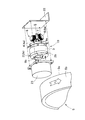
- FIG. 1 is an exploded perspective view of a non-contact generator 1 incorporating a rotating electrical machine 10 according to the first embodiment
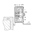
- FIG. 2 is a cross-sectional view of the non-contact generator 1 of FIG.
- the non-contact generator 1 includes a first rotating body 2, a rotor 3, a second rotating body 4, a stator 6, and a first permanent magnet 2a.
- the first rotating body 2, the rotor 3 and the second rotating body 4 constitute a rotating electrical machine 10, and the second rotating body 4 and the stator 6 constitute a cogging torque canceling unit 8.
- the first rotating body 2 is rotatable around a predetermined rotating shaft 9a.
- a bearing 9b is disposed around the rotation shaft 9a, and the rotation shaft 9a rotates clockwise or counterclockwise according to the rotation direction of the moving body 5.
- the first permanent magnet 2a of the first rotating body 2 has a plurality of magnetic poles 2b arranged circumferentially.
- FIG. 1 shows an example in which the first permanent magnet 2a has four magnetic poles 2b, the number of the magnetic poles 2b may be two or more and is not limited to four.
- the first rotating body 2 is disposed oppositely on one main surface of the moving body 5 that rotates or moves.
- the example of FIGS. 1 and 2 shows an example in which the moving body 5 rotates about its central axis, the moving body 5 may perform a translational motion.
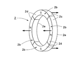
- FIG. 3 is an external view of the first rotating body 2 including the first permanent magnet 2a.
- the rotating shaft 9a of the first rotating body 2 and the rotating shaft of the moving body 5 are arranged in parallel, and at least a part of the first side surface 2d connected to the outer peripheral surface 2c of the first rotating body 2 is the moving body 5. Is disposed opposite to one side surface 5c continuous with the outer peripheral surface 5b. More specifically, two or more magnetic poles 2b among the plurality of magnetic poles 2b of the first rotating body 2 are arranged to face one side surface 5c of the moving body 5. Thereby, as will be described later, the amount of magnetic coupling between the first rotating body 2 and the moving body 5 can be increased, and the eddy current generated on the one side surface 5c of the moving body 5 can be increased.
- the moving body 5 is, for example, a vehicle wheel or a wheel.
- the moving body 5 generates an eddy current on the one side surface 5 c disposed to face the first rotating body 2.
- at least one side surface 5c of the moving body 5 needs to be formed of a conductive material such as metal.
- an eddy current is generated on one side surface 5c of the moving body 5 by the magnetic flux from each magnetic pole 2b of the first permanent magnet 2a constituting the first rotating body 2. Therefore, the interval between the first side surface 2d of the first rotating body 2 and the one side surface 5c of the moving body 5 is within a range in which the magnetic flux from each magnetic pole 2b of the first rotating body 2 can reach the moving body 5. Limited.
- Each magnetic pole 2b of the first permanent magnet 2a is magnetized in a direction toward the one side surface 5c of the opposed moving body 5 or in the opposite direction. Further, the magnetization directions of the adjacent magnetic poles 2b of the first permanent magnet 2a are opposite. In FIG. 3, the magnetization direction of each magnetic pole 2b of the first permanent magnet 2a is indicated by an arrow. As shown in FIG. 3, N poles and S poles are alternately arranged in a circumferential manner on the first side surface 2 d of the first rotating body 2. Further, the side surface 2e of the first rotating body 2 opposite to the first side surface 2d facing the moving body 5 has a polarity opposite to that of the one side surface.
- the first rotating body 2, the rotor 3, the second rotating body 4, and the stator 6 are covered with a cover 21.
- the stator 6 is fixed on the mounting plate 22.
- the cover 21 and the mounting plate 22 are not essential components, and their shapes and sizes are also arbitrary.
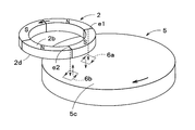
- FIG. 4 is a diagram for explaining the principle of rotation of the first rotating body 2 by eddy currents 5d and 5e generated on one side surface 5c of the moving body 5.
- FIG. 4 Of the plurality of magnetic poles 2b arranged circumferentially on the first side surface 2d of the first rotating body 2, the magnetic flux from the magnetic pole 2b arranged to face the one side surface 5c of the moving body 5 is in the direction of the one side surface 5c of the moving body 5 Propagate to.
- An air gap is formed between the first side surface 2d of the first rotating body 2 and one side surface 5c of the moving body 5, and the magnetic pole 2b from the first rotating body 2 propagates through the air gap.
- the magnetic flux from the edge e1 at the front of the N pole in the rotational direction reaches the one side surface 5c portion of the moving body 5.
- the direction of the eddy current 5d generated is different from the direction of the eddy current 5e generated at the side surface 5c of the moving body 5 where the magnetic flux from the edge e2 behind the N pole rotation direction arrives.
- the eddy current 5e generated by the magnetic flux from the edge e2 behind the rotation direction of the N pole flows in a direction to generate a magnetic flux in a direction opposite to the magnetic flux from the N pole.
- the eddy current 5d generated in one side surface 5c portion of the moving body 5 to which the magnetic flux from the edge e1 in the rotation direction of the N pole arrives flows in a direction in which the magnetic flux in the same direction as the magnetic flux from the N pole is generated. Any of the eddy currents 5d and 5e flows in a direction that prevents a change in magnetic flux from the first rotating body 2 accompanying the rotation of the moving body 5.
- the first rotating body 2 rotates at a surface speed slower than the surface speed of the one side surface 5c of the opposed moving body 5 so as to follow the moving surface of the one side surface 5c of the facing moving body 5.
- the principle of the rotation of the first rotating body 2 described above can also be explained by a repulsive force and an attractive force due to Lorentz force.
- the direction of the current is opposite to that of the current 5e, and a current in a constant direction always flows directly below the N pole.
- the currents caused by these eddy currents 5d and 5e receive a Lorentz force in the direction opposite to the rotation direction of the moving body 5 when the moving body 5 rotates in the direction of the arrow in FIG. Therefore, the first rotating body 2 that receives the magnetic flux generated by these eddy currents 5 d and 5 e rotates in response to the repulsive force and the attractive force of the Lorentz force in the rotating direction of the moving body 5.
- the first rotating body 2 and the moving body 5 move in the same direction on the opposing surfaces thereof. Therefore, as shown in FIG. 4, when the first rotating body 2 is disposed opposite to the rotational axis of the moving body 5, the rotating direction of the first rotating body 2 is opposite to the rotating direction of the moving body 5. become.
- the first side surface of the rotor 3 is joined to the second side surface opposite to the first side surface 2d of the first rotating body 2, and the second side surface opposite to the first side surface.
- the 1st side surface of the 2nd rotary body 4 is joined to.
- the first rotating body 2, the rotor 3 and the second rotating body 4 are all rotatable around a common rotating shaft 9a.
- the first rotating body 2, the rotor 3, and the second rotating body 4 rotate integrally around the rotation shaft 9a.
- the diameter size of the 1st rotary body 2, the rotor 3, and the 2nd rotary body 4 may be the same, or may each differ. In the example of FIG. 2, the diameter size of the first rotating body 2 and the rotor 3 is made substantially the same, and the diameter size of the second rotating body 4 is made smaller than that of the rotor 3. Thereby, the 2nd rotary body 4 can be accommodated inside the inner peripheral surface of the rotor 3.
- the second rotating body 4 has an annular second permanent magnet 4a in which a plurality of magnetic poles 2b are arranged in the circumferential direction.
- the number of magnetic poles of the second permanent magnet 4a is not particularly limited.
- a stator 6 is disposed inside the inner peripheral surface of the annular second permanent magnet 4a.
- the stator 6 is fixed and has a plurality of teeth 6a extending radially from the center of the second permanent magnet 4a.
- the stator 6 is made of a magnetic material, and a coil 7 is wound around each tooth 6a. These coils 7 are arranged at positions where the magnetic flux from the second permanent magnet 4a is linked, and generate an induced current corresponding to the amount of change in the linked magnetic flux.
- a non-uniform gap is provided between the tip position of the radially extending teeth 6a and the inner peripheral surface of the second permanent magnet 4a.
- FIG. 5 is a block diagram of the non-contact generator 1 according to the present embodiment.
- the non-contact generator 1 according to this embodiment includes a kinetic energy harvester (KEH: KineticKEnergy Harvester) 11, a generator 12, a drive control unit 13, and a cogging torque canceling unit 8. I have.
- KH KineticKEnergy Harvester
- the kinetic energy harvester 11 includes a moving body 5 and a first rotating body 2.
- the kinetic energy harvester 11 generates an eddy current on one side of the moving body 5 by the movement or rotation of the moving body 5, and the attractive force between the magnetic flux generated by this eddy current and the first permanent magnet 2 a of the first rotating body 2.
- the first rotating body 2 is rotated by the repulsive force.
- the kinetic energy harvester 11 has a function of converting the kinetic energy caused by the movement or rotation of the moving body 5 into the rotational energy of the first rotating body 2.
- the generator 12 includes the second rotating body 4 and the coil 7 of the stator 6.
- the second rotating body 4 When the first rotating body 2 rotates due to the movement or rotation of the moving body 5, the second rotating body 4 also rotates together with the first rotating body 2. Thereby, an alternating magnetic flux whose direction changes periodically is linked to the coil 7 wound around the tooth 6 a of the stator 6, and an induced current is generated in the coil 7.
- the generator 12 has a function of converting the rotational energy of the first rotating body 2 into an induced current flowing in the coil 7 via the second rotating body 4.
- the drive control unit 13 converts the induced current generated in the coil 7 into, for example, an AC voltage or a DC voltage, and performs control for driving various loads 14.
- the load 14 is a motor, an actuator, various sensors, etc., and the specific type is not ask
- the drive control unit 13 may store electric power corresponding to the induced current generated by the generator 12 in a capacitor (not shown).
- the cogging torque canceling unit 8 includes the second permanent magnet 4 a and the stator 6.
- the cogging torque canceling unit 8 cancels at least a part of the cogging torque generated in the first permanent magnet 2a by the relative shape and positional relationship between the moving body 5 and the first permanent magnet 2a. More specifically, the cogging torque canceling unit 8 adjusts the gap between the tip position of the teeth 6a extending radially of the stator 6 and the inner peripheral surface of the second permanent magnet 4a, for example, thereby adjusting the first permanent. At least a part of the cogging torque generated in the magnet 2a is canceled.
- cogging torque canceling unit 8 cancels the cogging torque generated in the first permanent magnet 2a is not limited to the above-described gap adjustment, as will be described later.
- cancellation means that the cogging torque generated in the first permanent magnet 2a by the moving body 5 is canceled by the cogging torque generated in another member, and the cogging torque generated in the first permanent magnet 2a. Including the case of reducing itself.
- the cogging torque is generated by the relative shape and positional relationship between the moving body 5 and the first permanent magnet 2a of the first rotating body 2, and is an eddy current generated on one side of the moving body 5. It has nothing to do with it.
- the cogging torque is constant regardless of the moving speed of the moving body 5.
- the cogging torque is generated due to non-uniformity of the attractive force between the moving body 5 that is a magnetic body and the first magnet of the first rotating body 2. That is, since the first permanent magnet 2a of the first rotating body 2 has a plurality of magnetic poles 2b in the circumferential direction, the strength of the attracting force to the moving body 5 varies depending on the rotation angle and rotation position of the first rotating body 2, This causes cogging torque.
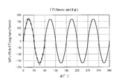
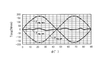
- FIG. 6 is a graph showing the cogging torque for one turn of the first rotating body 2.
- the horizontal axis of FIG. 6 is the rotation angle ⁇ (°) of the first rotating body 2, and the vertical axis is the cogging torque Tcog, harv (Nmm).
- the graph of FIG. 6 shows an example in which the first permanent magnet 2a of the first rotating body 2 has four magnetic poles 2b having the same length in the circumferential direction.
- the cogging torque has a waveform of one cycle every 90 °, and the ratio of the N pole and the S pole in a region where one side surface of the moving body 5 and one side surface of the first rotating body 2 overlap. When the values are equal, the cogging torque becomes zero.
- the absolute value of the cogging torque is maximized when the ratio of the N pole is maximum or the ratio of the S pole is maximum in a region where one side of the moving body 5 and one side of the first rotating body 2 overlap.
- the cogging torque is generated not only in the first rotating body 2 but also in the second rotating body 4.
- the cogging torque of the second rotating body 4 varies depending on the relative shape and positional relationship with the stator 6.
- the cogging torque canceling unit 8 ideally uses the cogging torque Tcog, harv ( ⁇ ) of the first rotating body 2 and the cogging torque Tcog, gen ( ⁇ of the second rotating body 4 as shown in the equation (1). ) To completely cancel out to zero.
- the cogging torque Tcog ( ⁇ ) is Fourier expanded as shown in the equation (2).
- Tcog ( ⁇ ) c 1 sin (4 ⁇ ) + d 1 cos (4 ⁇ ) + c 2 sin (8 ⁇ ) + d 2 cos (8 ⁇ ) + ... (2)
- ⁇ in equation (2) is the rotation angle of the rotor 3.
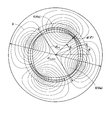
- FIG. 7 is a diagram showing a result of a two-dimensional FEM simulation of the generator 12 including the second rotating body 4 and the stator 6.
- the gap between the teeth 6a of the stator 6 and the second rotating body 4 is adjusted in order to cause the second rotating body 4 to generate a cogging torque that can cancel the cogging torque generated in the first rotating body 2.
- An example is shown.
- ⁇ is an angle from a predetermined reference direction of the stator 6 as shown in FIG.
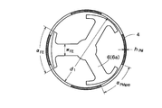
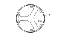
- FIG. 8A is a plan view showing the structure before optimizing the gap between the stator 6 and the second rotating body 4, and FIG. 8B is a plan view showing the structure after optimizing the gap.
- 8A and 8B show the structure of the stator 6 obtained by simulation.
- the shape of the tip position of the teeth 6a of the stator 6 in FIG. 8B is different from that in FIG. 8A, and thus the gap is optimized.
- the various parameters set when generating the structure of FIG. 8B by simulation are as shown in FIG.
- the width ⁇ FE of the teeth 6a of the stator 6 and the distance ⁇ PMgap between the magnetic poles 2b of the second permanent magnet 4a were used as parameters for calculating the structure of FIG. 8B.
- FIG. 10 is a flowchart showing an algorithm for optimizing the gap between the tip of the teeth 6a of the stator 6 and the second rotating body 4.
- the geometric parameters (geometry parameters) of the generator 12 having a preselected shape are initialized (step S1).
- the configuration of the generator 12 is evaluated by calculating the cogging torque as a function of the rotation angle ⁇ in the two-dimensional FEM simulation (step S2).
- the geometric parameters are repeatedly updated until the cogging torque reaches the target value (steps S3 and S4).
- step S3 the remaining value Tcog, rem of the cogging torque and the remaining value ratio Tcog, rem / Tcog, harv of the cogging torque are calculated according to the following equation (6).
- Tcog, rem Tcog, harv-Tcog, gen (6)
- step S3 it is determined whether or not the remaining value ratios Tcog, rem / Tcog, harv are less than ⁇ .
- the cogging torque Tcog, harv of the first rotating body 2 and the cogging torque Tcog, gen of the second rotating body 4 are continuous functions of the variable ⁇ . For this reason, it is essentially difficult to perform the optimization process. Therefore, the cogging torque is decomposed by the above-described equation (5) to obtain a vector c of the harmonic component of the cogging torque expressed by the following equation (7).
- the geometric parameter of the generator 12 is conveniently expressed by the vector a in the following equation (9).
- a multi-dimensional secant method related to the multi-dimensional Newton-Raphson method is used.
- the secant method described above is used as an approximation of the Jacobian matrix expressed by the following equation (10) for making the error function (in this case, c rem ) zero.
- the difference c gen of the cogging torque decomposition of the equation (8) described above is used as the value of the first column of the Jacobian matrix of the equation (10). This process is performed on all elements in the geometric parameter a, thereby obtaining all elements of the Jacobian matrix.
- the geometric parameter a is repeatedly updated until the remaining cogging torque value c rem becomes sufficiently small.
- the cogging torque is optimized for the three-phase outrunner generator 12.
- the stator 6 having the structure as shown in FIG. 8B was obtained.
- FIG. 11 is a diagram in which the horizontal axis represents the width and interval of the three teeth 6a arranged in the circumferential direction of the stator 6, and the vertical axis represents the gap between the tip of the tooth 6a and the second rotating body 4. While the shape of the stator 6 is slightly changed, the gap ( ⁇ PMgap ) between the permanent magnets is greatly increased. The comparison result between the initial state and the geometric parameter after optimization is shown in FIG.
- FIG. 13 is a diagram showing how the cogging torque changes during the optimization process. As can be seen from FIG. 13, by performing the optimization process, the cogging torque gradually converges to a desired sine wave. If the algorithm according to the present embodiment is used, the cogging torque can be optimized not only to the sine wave but also to a desired waveform.
- FIG. 14 is a diagram comparing the cogging torque Tcog, harv of the first rotating body 2 with the cogging torque Tcog, gen of the second rotating body 4 finally obtained by the above-described method.
- Tcog, harv and Tcong, gen are almost opposite in phase, and as a result, the overall cogging torque could be reduced by about 90%.
- the magnetic flux caused by the eddy current generated on one side surface of the moving body 5 due to the movement or rotation of the moving body 5 and the first rotating body 2 arranged opposite to the one side surface of the moving body 5 are used.
- the 1st rotary body 2 can be rotated by the attractive force and repulsive force with the magnetic flux of 1 permanent magnet 2a.
- the second rotating body 4 that rotates integrally with the first rotating body 2 is provided, and the tips of the teeth 6 a of the stator 6 disposed on the inner peripheral side of the second rotating body 4 and the second rotating body 4.
- the cogging torque generated by the rotation of the first rotating body 2 is generated in the second rotating body 4 and the two rotating bodies 4 cancel each other.
- the cogging torque can be reduced to near zero.
- cogging torque generated in the first rotating body 2 is generated in the second rotating body 4 by using the second rotating body 4 and the stator 6 that rotate integrally with the first rotating body 2.
- the specific means for canceling the cogging torque is not limited to that described in the first embodiment.
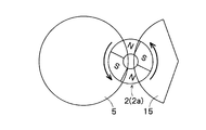
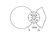
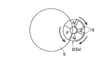
- FIG. 15A and FIG. 15B are diagrams for explaining the concept of the second embodiment.
- 15A and 15B show an example in which the yoke 15 is arranged point-symmetrically with the moving body 5 with respect to the first rotating body 2.
- the S pole is larger in area than the N pole, and counterclockwise cogging torque is generated.
- the S pole is larger in area than the N pole, so that counterclockwise cogging torque is also generated. Accordingly, the counterclockwise cogging torque is further increased as compared with the case without the yoke 15. In this case, the cogging torque of the first rotating body 2 cannot be canceled by the yoke 15.
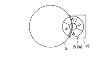
- FIG. 16A shows an example in which the yoke 15 is overlapped in almost all regions other than the region overlapping the moving body 5 of the first rotating body 2.
- the magnetic characteristic of the yoke 15 that is, the magnetic permeability is the same as the magnetic characteristic of the moving body 5 and the gap between the first rotating body 2 and the yoke 15 is equal to the gap between the moving body 5 and the first rotating body 2
- the cogging torque generated in the first rotating body 2 is reduced.
- the cogging torque itself is not generated in the first rotating body 2 rather than canceling out the cogging torque generated in the first rotating body 2 by the moving body 5.
- FIG. 16B shows an example of using a plurality of yokes 15 to optimize the location of each yoke 15 so as to cancel the cogging torque generated in the first rotating body 2 by the moving body 5.
- two yokes 15 are used, but it is desirable to optimize the magnetic characteristics such as the number, shape, and permeability of the yokes 15.
- simulation may be used as in the first embodiment.
- the yoke 15 in FIG. 16A and the yoke 15 in FIG. 16B constitute the cogging torque canceling unit 8.
- the yoke 15 in FIG. 16A reduces the cogging torque itself generated in the first rotating body 2 as described above, but is generated in the first rotating body 2 by the moving body 5 when the yoke 15 is not provided.
- the cogging torque is offset by providing the yoke 15, and as a result, the cogging torque itself generated in the first rotating body 2 is reduced. Therefore, the yoke 15 in FIG. 16A also functions as the cogging torque canceling unit 8.
- the cogging torque itself is not generated in the first rotating body 2 by arranging the yoke 15 so as to at least partially overlap the first permanent magnet 2 a of the first rotating body 2.
- the cogging torque generated in the first rotating body 2 by the moving body 5 can be canceled by the yoke 15.
- a second rotating body 4 separate from the first rotating body 2 is provided, and both the first rotating body 2 and the second rotating body 4 are disposed close to the moving body 5.
- FIG. 17 is a diagram for explaining the concept of the third embodiment.
- the cogging torque canceling unit 8 according to the third embodiment includes the second rotating body 4 and a synchronous rotating mechanism.
- the second rotating body 4 includes a second permanent magnet 4 a that is spaced from and arranged on one main surface of the moving body 5 and rotates around a predetermined rotation axis in accordance with the rotation or moving direction of the moving body 5.
- the synchronous rotating mechanism rotates the first rotating body 2 and the second rotating body 4 in synchronization.
- An example of the synchronous rotation mechanism is a timing belt 16 that spans the rotation axes of the first rotating body 2 and the second rotating body 4.
- the synchronous rotation mechanism is not necessarily limited to the timing belt 16 and may be a gear or the like.
- the second rotating body 4 is disposed so as to overlap the moving body 5, similarly to the first rotating body 2.
- the area where the first rotating body 2 and the moving body 5 overlap includes the N pole and the S pole in equal areas, whereas the second rotating body 4 and the moving body 5
- the overlapping region contains more S poles than N poles. That is, the second rotator 4 is arranged 45 ° apart from the first rotator 2. Thereby, the cogging torque generated in the first rotating body 2 by the moving body 5 can be canceled by the cogging torque generated in the second rotating body 4 by the moving body 5.
- the diameter size, the number of magnetic poles, the magnetic characteristics, and the gap between the moving body 5 and the first rotating body 2 and the second rotating body 4 are common.
- the moving body 5 may rotate.
- the first rotating body 2 and the second rotating body 4 are arranged so as to overlap the moving body 5, and the first rotating body 2 and the second rotating body 4 rotate integrally.
- the cogging torque generated in the first rotating body 2 by the moving body 5 is The cogging torque generated in the second rotating body 4 can be canceled out.
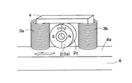
- FIG. 18A is a diagram illustrating a first example of the rotating electrical machine 10 to which the cogging torque canceling unit 8 can be attached.
- the non-contact generator 1 of FIG. 18A includes a first permanent magnet 2a that rotates around a rotation axis, two coils 7 (a first coil 7a and a second coil 7b), and a yoke 15.
- the first permanent magnet 2a is disposed on the main surface 5c of the moving body 5 that rotates or moves to be spaced apart from the first permanent magnet 2a, and rotates according to the rotation or moving direction of the moving body 5.
- the first permanent magnet 2a has at least two magnetic poles 2b, and the magnetization direction of each magnetic pole 2b is the normal direction of the outer peripheral surface of the first permanent magnet 2a.
- the outer peripheral surface 2c of the first permanent magnet 2a is spaced apart from the one main surface 5c of the moving body 5, and the first permanent magnet 2a rotates without contacting the one main surface 5c of the moving body 5. It is supposed to be free.
- one first coil 7 a of the two coils 7 is disposed on the rear side of the first permanent magnet 2 a with respect to the rotation or movement direction of the moving body 5.
- the other second coil 7 b is arranged on the front side of the first permanent magnet 2 a with respect to the rotation or movement direction of the moving body 5.
- the first and second coils 7 a and 7 b are arranged on the main surface 5 c of the moving body 5 so as to be separated from each other.
- a U-shaped yoke 15 is disposed inside and above the first and second coils 7a and 7b. There is a gap between the yoke 15 and the first permanent magnet 2a, and similarly there is a gap between the first permanent magnet 2a and the first and second coils 7a and 7b. These gaps are air gaps. Therefore, the first permanent magnet 2 a rotates within a region surrounded by one main surface of the moving body 5, the first and second coils 7 a and 7 b, and the yoke 15.
- the coil 7 in FIG. 18A may be disposed at a location where the total magnetic flux from the first permanent magnet 2a is concentrated, and the arrangement example of the coil 7 in FIG. 18A is merely an example. Further, the shape of the yoke 15 is not limited to that shown in FIG. 18A.
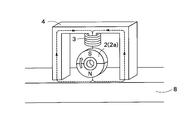
- FIG. 18B is a diagram illustrating a second example of the rotating electrical machine 10 to which the cogging torque canceling unit 8 can be attached, and is a diagram illustrating an example in which power is generated by one coil 7.
- a coil 7 wound around a yoke 15 is disposed above the first permanent magnet 2a.
- the yoke 15 extends from above the first permanent magnet 2a to both sides in the moving direction of the moving body 5, and is disposed so as to surround the first permanent magnet 2a. Since the coil 7 links almost all the magnetic flux from the first permanent magnet 2a, it is not always necessary to provide a plurality of coils 7.
- the location where the coil 7 is disposed may be a location where all the magnetic flux from the first permanent magnet 2a is concentrated (for example, in the vicinity of at least one of the north and south poles of the first permanent magnet 2a).
- the cogging torque canceling unit 8 described in the first to third embodiments is also provided. desirable.
- 1 non-contact generator 2 first rotating body, 2a first permanent magnet, 2b magnetic pole, 3 rotor, 4 second rotating body, 6 stator, 7 coil, 8 cogging torque canceling unit, 9a rotating shaft, 10 rotating electric machine, 11 Kinetic energy harvester, 12 generator, 13 drive controller
Landscapes
- Engineering & Computer Science (AREA)
- Power Engineering (AREA)
- Permanent Magnet Type Synchronous Machine (AREA)
- Connection Of Motors, Electrical Generators, Mechanical Devices, And The Like (AREA)
- Dynamo-Electric Clutches, Dynamo-Electric Brakes (AREA)
- Permanent Field Magnets Of Synchronous Machinery (AREA)
Abstract
磁気効率がよく、磁束の漏れも少なく、かつコギングトルクに対する対策を行った回転電機および非接触発電機を提供する。回転電機10は、回転または移動する移動体の一主面上に離隔して対向配置され、移動体の回転または移動方向に応じて所定の回転軸回りに回転する第1永久磁石2aを有する第1回転体2と、移動体と第1永久磁石との相対的な形状および位置関係により第1永久磁石に発生するコギングトルクの少なくとも一部を相殺するコギングトルク相殺部8と、を備え、第1回転体2は、移動体5の一主面上に第1永久磁石からの磁束の変化を妨げる方向に発生される渦電流に基づいて第1永久磁石に働く反発力および誘引力により、第1回転軸周りに回転し、第1回転体の移動体に対向配置される一側面の表面速度は、対向配置される移動体の一主面の表面速度より遅い。
Description
本発明は、非接触で回転する回転電機と、非接触で発電する非接触発電機とに関する。
米国特許公開公報2014/0132155号には、非接触で発電する自転車用ダイナモが開示されている。上述した公知文献の自転車用ダイナモは、自転車のホイールの回転軸と直交する方向に延びる回転軸周りに回転する円環状の永久磁石の外周面を、ホイールの外周面に連なる一側面から離隔して配置している。
永久磁石は、複数の磁極を周方向に並べて配置したものであり、隣接する磁極では、磁化方向が逆になっている。例えば、永久磁石のN極がホイールの一側面に対向配置された状態でホイールが回転すると、永久磁石からの磁束の変化を妨げる方向に、ホイールの一側面に渦電流が発生する。この渦電流による磁束と永久磁石からの磁束との反発力および誘引力により、永久磁石は、ホイールの回転方向に回転する。
よって、永久磁石の周囲をコイルで巻回して、永久磁石からの磁束がコイルを鎖交するようにすれば、コイルから誘導電力を取り出すことができる。
1.ホイールの一側面に対向配置される永久磁石の面積が限られているため、ホイールと永久磁石との磁気結合量を大きくできない。よって、ホイールに発生する渦電流が小さくなり、永久磁石の回転力も弱くなる。
2.上述した公知文献では、永久磁石に単一相のコイルを巻回しているが、単一相のコイルでは、コイルが巻回していない部分の永久磁石の磁束を有効利用できないため、鎖交磁束量を増やすことはできない。また、コイルが巻回している部分の永久磁石の極性の向きが、回転軸を中心に対称である場合、常にコイルを鎖交する磁束の総量が打ち消し合ってしまうため、発電できないという問題がある。
3.永久磁石からの磁束は、空気中を伝搬するため、大きな磁気抵抗を受けることになり、磁気効率がよいとはいえない。
4.ヨークを用いていないため、磁束の漏れが生じやすく、また周囲に導電材料または磁性材料があると、磁路が変化してしまい、発電量に影響を与えてしまうおそれがある。
5.ホイールの一側面に対向配置される永久磁石の磁極位置によっては、ホイールを回転させたときに、なかなか永久磁石が回転しない場合がありうる。これは、永久磁石とホイール間に生じるコギングトルクによるものである。米国特許公開公報2014/0132155号は、コギングトルクに対する対策を何ら行っていない。
本発明は、上述した課題に鑑みてなされたものであり、その目的は、磁気効率がよく、磁束の漏れも少なく、かつコギングトルクに対する対策を行った回転電機および非接触発電機を提供することである。
上記の課題を解決するために、本発明の一態様では、回転または移動する導体である移動体の一主面上に離隔して対向配置され、前記移動体の回転または移動方向に応じて発生するローレンツ力によって所定の回転軸回りに回転する第1永久磁石を有する第1回転体と、
前記移動体と前記第1永久磁石との相対的な形状および位置関係により前記第1永久磁石に発生するコギングトルクを低減または相殺するコギングトルク相殺部と、を備える回転電機が提供される。
前記移動体と前記第1永久磁石との相対的な形状および位置関係により前記第1永久磁石に発生するコギングトルクを低減または相殺するコギングトルク相殺部と、を備える回転電機が提供される。
本発明の他の一態様では、回転または移動する移動体の一主面上に離隔して対向配置され、前記移動体の回転または移動方向に応じて所定の回転軸回りに回転する第1永久磁石を有する第1回転体と、
前記移動体と前記第1永久磁石との相対的な形状および位置関係により前記第1永久磁石に発生するコギングトルクを低減または相殺するコギングトルク相殺部と、を備え、
前記第1回転体は、前記移動体の前記一主面上に前記第1永久磁石からの磁束の変化を妨げる方向に発生される渦電流に基づいて前記第1永久磁石に働く反発力および誘引力により、前記第1回転軸周りに回転し、
前記第1回転体の前記移動体に対向配置される前記一側面の表面速度は、対向配置される前記移動体の前記一主面の表面速度より遅い回転電機が提供される。
前記移動体と前記第1永久磁石との相対的な形状および位置関係により前記第1永久磁石に発生するコギングトルクを低減または相殺するコギングトルク相殺部と、を備え、
前記第1回転体は、前記移動体の前記一主面上に前記第1永久磁石からの磁束の変化を妨げる方向に発生される渦電流に基づいて前記第1永久磁石に働く反発力および誘引力により、前記第1回転軸周りに回転し、
前記第1回転体の前記移動体に対向配置される前記一側面の表面速度は、対向配置される前記移動体の前記一主面の表面速度より遅い回転電機が提供される。
前記コギングトルク相殺部は、前記移動体と前記第1永久磁石との相対的な形状および位置関係により前記第1永久磁石に発生するコギングトルクの逆位相のコギングトルクを発生させてもよい。
前記コギングトルク相殺部は、前記第1永久磁石とは異なる第2永久磁石、または磁性体を用いて、前記コギングトルクを低減または相殺してもよい。
前記コギングトルク相殺部は、
前記第1永久磁石とは異なる第2永久磁石を有し、前記第1回転体に同期して回転する第2回転体と、
前記第2永久磁石と磁気結合する第1磁性体と、を有してもよい。
前記第1永久磁石とは異なる第2永久磁石を有し、前記第1回転体に同期して回転する第2回転体と、
前記第2永久磁石と磁気結合する第1磁性体と、を有してもよい。
前記コギングトルク相殺部は、前記第2回転体と前記第1磁性体とのギャップを調整することにより、前記コギングトルクを低減してもよい。
前記第2回転体は、前記第1永久磁石とともに、前記回転軸回りに回転する円環部材であってもよく、
前記第1磁性体は、前記円環部材の内周側に配置され、前記円環部材の内周面とのギャップを調整することにより、前記コギングトルクを低減してもよい。
前記第1磁性体は、前記円環部材の内周側に配置され、前記円環部材の内周面とのギャップを調整することにより、前記コギングトルクを低減してもよい。
前記第2永久磁石からの磁束が鎖交する位置に配置され、鎖交した磁束の変化量に応じた誘導電流を発生するコイルを備えてもよい。
前記コギングトルク相殺部は、前記第1永久磁石と磁気結合する第2磁性体を有してもよく、
前記コギングトルク相殺部は、前記第1永久磁石と前記第2磁性体とが重なり合う領域を調整することにより、前記コギングトルクを低減してもよい。
前記コギングトルク相殺部は、前記第1永久磁石と前記第2磁性体とが重なり合う領域を調整することにより、前記コギングトルクを低減してもよい。
前記第2磁性体は、ヨークであってもよい。
前記コギングトルク相殺部は、
前記移動体の一主面上に離隔して対向配置され、前記移動体の回転または移動方向に応じて所定の回転軸回りに回転する第2永久磁石を有する第2回転体と、
前記第1回転体と前記第2回転体とを同期させて回転させる同期回転機構と、を有してもよく、
前記移動体と重なり合う前記第2永久磁石の磁極を、前記移動体と重なり合う前記第1永久磁石の磁極と相違させることで、前記コギングトルクを低減してもよい。
前記移動体の一主面上に離隔して対向配置され、前記移動体の回転または移動方向に応じて所定の回転軸回りに回転する第2永久磁石を有する第2回転体と、
前記第1回転体と前記第2回転体とを同期させて回転させる同期回転機構と、を有してもよく、
前記移動体と重なり合う前記第2永久磁石の磁極を、前記移動体と重なり合う前記第1永久磁石の磁極と相違させることで、前記コギングトルクを低減してもよい。
本発明の他の一態様では、回転または移動する導体である移動体の一主面上に離隔して対向配置され、前記移動体の回転または移動方向に応じて発生するローレンツ力によって所定の回転軸回りに回転する第1永久磁石を有する第1回転体と、
前記第1回転体の回転による運動エネルギを電気エネルギに変換する発電部と、を備え、
前記発電部は、前記移動体と前記第1永久磁石との相対的な形状および位置関係により前記第1永久磁石に発生するコギングトルクを低減または相殺するコギングトルク相殺部を有する非接触発電機が提供される。
前記第1回転体の回転による運動エネルギを電気エネルギに変換する発電部と、を備え、
前記発電部は、前記移動体と前記第1永久磁石との相対的な形状および位置関係により前記第1永久磁石に発生するコギングトルクを低減または相殺するコギングトルク相殺部を有する非接触発電機が提供される。
本発明の他の一態様では、回転または移動する移動体の一主面上に離隔して対向配置され、前記移動体の回転または移動方向に応じて所定の回転軸回りに回転する第1永久磁石を有する第1回転体と、
前記第1回転体の回転による運動エネルギを電気エネルギに変換する発電部と、を備え、
前記発電部は、前記移動体と前記第1永久磁石との相対的な形状および位置関係により前記第1永久磁石に発生するコギングトルクを低減または相殺するコギングトルク相殺部を有し、
前記第1回転体は、前記移動体の前記一主面上に前記第1永久磁石からの磁束の変化を妨げる方向に発生される渦電流に基づいて前記第1永久磁石に働く反発力および誘引力により、前記第1回転軸周りに回転し、
前記第1回転体の前記移動体に対向配置される前記一側面の表面速度は、対向配置される前記移動体の前記一主面の表面速度より遅い、非接触発電機が提供される。
前記第1回転体の回転による運動エネルギを電気エネルギに変換する発電部と、を備え、
前記発電部は、前記移動体と前記第1永久磁石との相対的な形状および位置関係により前記第1永久磁石に発生するコギングトルクを低減または相殺するコギングトルク相殺部を有し、
前記第1回転体は、前記移動体の前記一主面上に前記第1永久磁石からの磁束の変化を妨げる方向に発生される渦電流に基づいて前記第1永久磁石に働く反発力および誘引力により、前記第1回転軸周りに回転し、
前記第1回転体の前記移動体に対向配置される前記一側面の表面速度は、対向配置される前記移動体の前記一主面の表面速度より遅い、非接触発電機が提供される。
前記コギングトルク相殺部は、前記第1永久磁石とは別個に前記発電部が有する第2永久磁石を用いて、前記コギングトルクを低減または相殺してもよい。
前記コギングトルク相殺部は、
前記第1永久磁石とは異なる第2永久磁石を有し、前記第1回転体に同期して回転する第2回転体と、
前記第2永久磁石と磁気結合する第1磁性体と、を有し、
前記発電部は、前記第2永久磁石からの磁束が鎖交する位置に配置され、鎖交した磁束の変化量に応じた誘導電流を発生するコイルを有してもよい。
前記第1永久磁石とは異なる第2永久磁石を有し、前記第1回転体に同期して回転する第2回転体と、
前記第2永久磁石と磁気結合する第1磁性体と、を有し、
前記発電部は、前記第2永久磁石からの磁束が鎖交する位置に配置され、鎖交した磁束の変化量に応じた誘導電流を発生するコイルを有してもよい。
前記コギングトルク相殺部は、前記第1永久磁石と磁気結合する第2磁性体を有し、
前記コギングトルク相殺部は、前記第1永久磁石と前記第2磁性体とが重なり合う領域を調整することにより、前記コギングトルクを低減してもよい。
前記コギングトルク相殺部は、前記第1永久磁石と前記第2磁性体とが重なり合う領域を調整することにより、前記コギングトルクを低減してもよい。
前記コギングトルク相殺部は、
前記移動体の一主面上に離隔して対向配置され、前記移動体の回転または移動方向に応じて所定の回転軸回りに回転する第2永久磁石を有する第2回転体と、
前記第1回転体と前記第2回転体とを同期させて回転させる同期回転機構と、を有し、 前記移動体と重なり合う前記第2永久磁石の磁極を、前記移動体と重なり合う前記第1永久磁石の磁極と相違させることで、前記コギングトルクを低減してもよい。
前記移動体の一主面上に離隔して対向配置され、前記移動体の回転または移動方向に応じて所定の回転軸回りに回転する第2永久磁石を有する第2回転体と、
前記第1回転体と前記第2回転体とを同期させて回転させる同期回転機構と、を有し、 前記移動体と重なり合う前記第2永久磁石の磁極を、前記移動体と重なり合う前記第1永久磁石の磁極と相違させることで、前記コギングトルクを低減してもよい。
前記発電部は、前記第1永久磁石からの磁束が鎖交する位置に配置され、鎖交した磁束の変化量に応じた誘導電流を発生するコイルを有してもよい。
本発明によれば、磁気効率がよく、磁束の漏れも少なく、かつコギングトルクに対する対策を行った回転電機および非接触発電機を提供できる。
以下、本発明の実施の形態について、詳細に説明する。
(第1の実施形態)
図1は第1の実施形態による回転電機10を内蔵した非接触発電機1の分解斜視図、図2は図1の非接触発電機1の断面図である。
図1は第1の実施形態による回転電機10を内蔵した非接触発電機1の分解斜視図、図2は図1の非接触発電機1の断面図である。
図1および図2に示すように、本実施形態による非接触発電機1は、第1永久磁石2aからなる第1回転体2と、ロータ3と、第2回転体4と、ステータ6と、コイル7と、を備えている。第1回転体2、ロータ3および第2回転体4が回転電機10を構成し、第2回転体4とステータ6とがコギングトルク相殺部8を構成している。
第1回転体2は、所定の回転軸9a回りに回転自在とされている。回転軸9aの周囲にはベアリング9bが配置されており、回転軸9aは移動体5の回転方向に合わせて、時計回りまたは反時計回りに回転する。
第1回転体2の第1永久磁石2aは、周状に配置された複数の磁極2bを有する。図1では、第1永久磁石2aが4つの磁極2bを有する例を示すが、磁極2bの数は2つ以上であればよく、4つに限定されるわけではない。
第1回転体2は、回転または移動する移動体5の一主面上に離隔して対向配置されている。図1および図2の例では、移動体5がその中心軸回りに回転する例を示しているが、移動体5は並進運動をするものであってもよい。
図3は第1永久磁石2aからなる第1回転体2の外観図である。第1回転体2の回転軸9aと、移動体5の回転軸とは平行に配置されており、第1回転体2の外周面2cに連なる第1側面2dの少なくとも一部は、移動体5の外周面5bに連なる一側面5cに対向配置されている。より具体的には、第1回転体2が有する複数の磁極2bのうち、2つ以上の磁極2bが移動体5の一側面5cに対向配置されている。これにより、後述するように、第1回転体2と移動体5との磁気結合量を増やすことができ、移動体5の一側面5c上に生じる渦電流を増大させることができる。
移動体5は、例えば車両の車輪やホイールなどである。移動体5は、第1回転体2に対向配置された一側面5cに渦電流を発生させる。渦電流を発生できるように、移動体5の少なくとも一側面5cは、金属などの導電材料で形成されている必要がある。
本実施形態では、第1回転体2を構成する第1永久磁石2aの各磁極2bからの磁束により、移動体5の一側面5cに渦電流を発生させる。よって、第1回転体2の第1側面2dと移動体5の一側面5cとの間の間隔は、第1回転体2の各磁極2bからの磁束が移動体5に到達可能な範囲内に制限される。
第1永久磁石2aの各磁極2bは、対向する移動体5の一側面5cに向かう方向またはその反対方向に磁化されている。また、第1永久磁石2aの隣接する磁極2b同士の磁化方向は逆である。図3では、第1永久磁石2aの各磁極2bの磁化方向を矢印で示している。図3に示すように、第1回転体2の第1側面2dには、周状にN極とS極が交互に並んでいる。また、第1回転体2の移動体5に対向する第1側面2dとは反対側の側面2eは、一側面とは逆極性になる。
図2に示すように、第1回転体2、ロータ3、第2回転体4およびステータ6は、カバー21によって覆われている。また、ステータ6は、実装プレート22上に固定されている。なお、カバー21や実装プレート22は必須の構成部品ではなく、その形状やサイズも任意である。
図4は移動体5の一側面5cに発生する渦電流5d,5eにより第1回転体2が回転する原理を説明する図である。第1回転体2の第1側面2d上に周状に並ぶ複数の磁極2bのうち、移動体5の一側面5cに対向配置された磁極2bからの磁束は、移動体5の一側面5c方向に伝搬する。第1回転体2の第1側面2dと移動体5の一側面5cとの間は、エアギャップであり、第1回転体2からの磁極2bはこのエアギャップを伝搬する。
移動体5が回転すると、移動体5の一側面5cには、第1回転体2からの磁束の変化を妨げる方向に渦電流が生じ、この渦電流による磁束と第1回転体2からの磁束との相互作用(反発力および誘引力)により、第1回転体2は回転する。ただし、第1回転体2の第1側面2dの表面速度は、対向する移動体5の一側面5cの表面速度よりも遅くなる。
例えば、第1回転体2のN極が移動体5の一側面5cに対向配置されている場合、N極の回転方向前方のエッジe1からの磁束が到達する移動体5の一側面5c部分に発生する渦電流5dの向きと、N極の回転方向後方のエッジe2からの磁束が到達する移動体5の一側面5c部分に発生する渦電流5eの向きとは相違している。N極の回転方向後方のエッジe2からの磁束により発生する渦電流5eは、N極からの磁束とは反対方向の磁束を発生させる向きに流れる。一方、N極の回転方向前方のエッジe1からの磁束が到達する移動体5の一側面5c部分に発生する渦電流5dは、N極からの磁束と同方向の磁束を発生させる向きに流れる。いずれの渦電流5d,5eも、移動体5の回転に伴う第1回転体2からの磁束の変化を妨げる方向に流れる。
上述したように、第1回転体2のN極の回転方向前方のエッジe1側では、渦電流5dによる磁束と第1回転体2のN極からの磁束との方向が同じになることから、互いに引き寄せ合う誘引力が働く。一方、第1回転体2のN極の回転方向後方のエッジe2側では、渦電流5eによる磁束と第1回転体2のN極からの磁束とは反対方向になることから、互いに反発し合う反発力が働く。第1回転体2の第1側面2dの表面速度が、対向する移動体5の一側面5cの表面速度より遅い場合には、上述した、第1回転体2と渦電流5d、5eの関係が常に成り立つ。これにより、第1回転体2は、対向する移動体5の一側面5cの移動表面を追いかけるようにして、対向する移動体5の一側面5cの表面速度よりも遅い表面速度で回転することになる。
なお、上述した第1回転体2の回転の原理は、ローレンツ力による反発力および誘引力にて説明することもできる。上述したように、第1回転体2のN極の回転方向前方のエッジe1からの磁束による発生する渦電流5dと、第1回転体2の回転方向後方のエッジe2からの磁束による発生する渦電流5eとは、電流の向きが逆になっていて、N極の直下には常に一定方向の電流が流れる。これら渦電流5d,5eによる電流は、移動体5が図4の矢印の向きに回転する場合には、移動体5の回転方向とは反対方向のローレンツ力を受ける。よって、これら渦電流5d,5eによる磁束を受ける第1回転体2は、移動体5の回転方向への、ローレンツ力の反発力および誘引力を受けて回転する。
このように、第1回転体2と移動体5は、両者の対向面同士では同一方向に移動する。よって、図4のように、第1回転体2が移動体5の回転軸からずれて対向配置されている場合には、第1回転体2の回転方向は移動体5の回転方向とは逆になる。
図1および図2に示すように、第1回転体2の第1側面2dと反対側の第2側面にはロータ3の第1側面が接合され、この第1側面と反対側の第2側面には第2回転体4の第1側面が接合されている。
第1回転体2、ロータ3および第2回転体4は、いずれも共通の回転軸9a回りに回転自在とされている。この回転軸9a回りに、第1回転体2、ロータ3および第2回転体4は一体に回転する。第1回転体2、ロータ3および第2回転体4の径サイズは同じでも、それぞれ異なっていてもよい。図2の例では、第1回転体2とロータ3の径サイズを略同一とし、第2回転体4の径サイズをロータ3よりも小さくしている。これにより、ロータ3の内周面の内側に第2回転体4を収納できるようにしている。
第2回転体4は、図1および図2に示すように、周方向に複数の磁極2bが配置された円環状の第2永久磁石4aを有する。第2永久磁石4aの磁極数は特に問わない。
円環状の第2永久磁石4aの内周面の内側には、ステータ6が配置されている。ステータ6は、固定されており、第2永久磁石4aの中心から放射状に伸びる複数のティース6aを有する。ステータ6は、磁性体で形成されており、各ティース6aにはコイル7が巻回されている。これらコイル7は、第2永久磁石4aからの磁束が鎖交する位置に配置されており、鎖交した磁束の変化量に応じた誘導電流を発生させる。放射状に伸びるティース6aの先端位置と第2永久磁石4aの内周面との間には不均一なギャップが設けられている。
図5は本実施形態による非接触発電機1のブロック図である。図5に示すように、本実施形態による非接触発電機1は、運動エネルギ・ハーベスタ(KEH:Kinetic Energy Harvester)11と、発電機12と、駆動制御部13と、コギングトルク相殺部8とを備えている。
運動エネルギ・ハーベスタ11は、移動体5と第1回転体2とを含んで構成されている。運動エネルギ・ハーベスタ11は、移動体5の移動または回転により、移動体5の一側面に渦電流を生じさせ、この渦電流による磁束と第1回転体2の第1永久磁石2aとの誘引力および反発力により、第1回転体2を回転させる。このように、運動エネルギ・ハーベスタ11は、移動体5の移動または回転による運動エネルギを、第1回転体2の回転エネルギに変換する機能を持っている。
発電機12は、第2回転体4とステータ6のコイル7とを含んで構成されている。移動体5の移動または回転により第1回転体2が回転すると、第1回転体2と一体に第2回転体4も回転する。これにより、ステータ6のティース6aに巻回されたコイル7には、周期的に方向が変化する交番磁束が鎖交し、コイル7に誘導電流が発生する。このように、発電機12は、第1回転体2の回転エネルギを、第2回転体4を介して、コイル7に流れる誘導電流に変換する機能を持っている。
駆動制御部13は、コイル7に発生した誘導電流を例えば交流電圧や直流電圧に変換して、種々の負荷14を駆動する制御を行う。負荷14は、モータやアクチュエータ、各種センサなどであり、その具体的な種類は問わない。あるいは、駆動制御部13は、発電機12で発生した誘導電流に応じた電力を不図示の蓄電器に蓄電してもよい。
コギングトルク相殺部8は、第2永久磁石4aとステータ6とを含んで構成されている。コギングトルク相殺部8は、移動体5と第1永久磁石2aとの相対的な形状および位置関係により第1永久磁石2aに発生するコギングトルクの少なくとも一部を相殺する。より具体的には、コギングトルク相殺部8は、例えば、ステータ6の放射状に延びるティース6aの先端位置と第2永久磁石4aの内周面との間のギャップを調整することで、第1永久磁石2aに発生するコギングトルクの少なくとも一部を相殺する。なお、コギングトルク相殺部8が第1永久磁石2aに発生するコギングトルクを相殺する具体的な手段は、後述するように、上述したギャップの調整には限定されない。また、本明細書において、「相殺」とは、移動体5により第1永久磁石2aに生じたコギングトルクを別の部材に生じるコギングトルクによって相殺する場合と、第1永久磁石2aに生じるコギングトルク自体を低減する場合とを含む趣旨である。
ここで、コギングトルクとは、移動体5と第1回転体2の第1永久磁石2aとの相対的な形状および位置関係によって発生するものであり、移動体5の一側面に発生する渦電流とは無関係である。移動体5の移動速度によらず、コギングトルクは一定になる。コギングトルクは、磁性体である移動体5と第1回転体2の第1磁石との吸着力の不均一性が原因となって発生する。すなわち、第1回転体2の第1永久磁石2aは周方向に複数の磁極2bを有するため、第1回転体2の回転角度や回転位置によって、移動体5への吸着力に強弱が生じ、これが原因となってコギングトルクが発生する。
図6は第1回転体2の1周分のコギングトルクを表すグラフである。図6の横軸は第1回転体2の回転角度φ(°)、縦軸はコギングトルクTcog,harv(Nmm)である。図6のグラフは、第1回転体2の第1永久磁石2aが周方向に等しい長さの4つの磁極2bを有する例を示している。図6からわかるように、コギングトルクは、90°ごとに1周期の波形であり、移動体5の一側面と第1回転体2の一側面とが重なり合う領域におけるN極とS極との割合が等しいときがコギングトルクがゼロとなる。移動体5の一側面と第1回転体2の一側面とが重なり合う領域におけるN極の割合が最大、またはS極の割合が最大のときがコギングトルクの絶対値が最大になる。
コギングトルクは、第1回転体2だけでなく、第2回転体4にも発生する。第2回転体4のコギングトルクは、ステータ6との相対的形状および位置関係によって変化する。
コギングトルク相殺部8は、理想的には、(1)式に示すように、第1回転体2のコギングトルクTcog,harv(φ)を、第2回転体4のコギングトルクTcog,gen(φ)により、完全に相殺してゼロにする。
Tcog,gen(φ)+Tcog,harv(φ)=0 …(1)
よって、第2回転体4のコギングトルクTcog,gen(φ)は、理想的には、Tcog,gen(φ)=-Tcog,harv(φ)である。
次に、コギングトルク相殺部8の処理動作について詳述する。以下では、ステータ6の放射状に延びるティース6aの先端位置と第2回転体4の内周面とのギャップを調整して、第1回転体2のコギングトルクを相殺する例を説明する。
FEM(Finite Element Method)シミュレーションや解析的導出法によりコギングトルクを解析するには、(2)式に示すように、コギングトルクTcog(φ)をフーリエ展開する。
Tcog(φ)=c1sin(4φ)+d1cos(4φ)+c2sin(8φ)+d2cos(8φ)+… (2)
ここで、(2)式のφはロータ3の回転角度である。図6に示した波形で、かつ(1)式を満たすコギングトルクを得るには、(2)式の右辺の第1項以外はゼロにする必要がある。
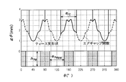
図7は第2回転体4とステータ6を含んで構成された発電機12の二次元FEMシミュレーションの結果を示す図である。図7は、第1回転体2に発生したコギングトルクを相殺できるようなコギングトルクを第2回転体4に発生させるために、ステータ6のティース6aと第2回転体4とのギャップを調整した例を示している。
図7のギャップg(θ)は、以下の(3)式で表される。
g(θ)=gnom・(1+a1cos(4θ) …(3)
ここで、θは、図7に示すように、ステータ6の所定の基準方向からの角度である。
(3)式に、以下の(4)式の項を追加することで、エアギャップ変調の概念を採り入れることができる。

この(4)式は、エアギャップを最適化するためのベースとなる。コギングトルクTcog(φ)は、結果的に以下の(5)式で表される。

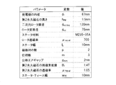
図8Aはステータ6と第2回転体4とのギャップを最適化する前の構造を示す平面図、図8Bはギャップを最適化した後の構造を示す平面図である。図8Aと図8Bは、シミュレーションにより得られたステータ6の構造を示している。図8Bのステータ6のティース6aの先端位置の形状は、図8Aとは相違しており、これにより、ギャップを最適化している。
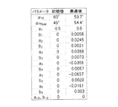
図8Bの構造をシミュレーションにより生成するにあたって設定した各種のパラメータは、図9の通りである。図9に示したパラメータ以外に、ステータ6のティース6aの幅αFEと第2永久磁石4aの磁極2b間の間隔αPMgapを図8Bの構造を計算するためのパラメータとして用いた。
図10はステータ6のティース6a先端と第2回転体4とのギャップを最適化するアルゴリズムを示すフローチャートである。まず、予め選択した形状の発電機12の幾何学的パラメータ(geometry parameters)を初期化する(ステップS1)。次に、二次元FEMシミュレーションにて、回転角度φの関数としてコギングトルクを計算することで、発電機12の構成を評価する(ステップS2)。その後、コギングトルクが目標値に到達するまで、幾何学的パラメータの更新を繰り返す(ステップS3、S4)。
シミュレーションの不確実性により、全体的なコギングトルクが(1)式のようなゼロにはならない場合もありうる。このため、ステップS3では、以下の(6)式に従って、コギングトルクの残値Tcog,remとコギングトルクの残値割合Tcog,rem/Tcog,harvを計算する。
Tcog,rem=Tcog,harv-Tcog,gen …(6)
上述したステップS3では、残値割合Tcog,rem/Tcog,harvがδ未満か否かを判定する。一例として、δ=0.1に設定される。δ=0.1であれば、全体的なコギングトルクを90%まで削減することができる。ステップS3がNOであれば、幾何学的パラメータを更新して(ステップS4)、ステップS2以降の処理を繰り返す。ステップS3がYESであれば、図10の処理を終了する。
なお、第1回転体2のコギングトルクTcog,harvと第2回転体4のコギングトルクTcog,genは、連続的な変数φの関数である。このため、本質的に最適化処理を行うのは困難である。そこで、上述した(5)式によるコギングトルクの分解を行って、以下の(7)式に示すコギングトルクの高調波成分のベクトルcを求める。

同様の分解が第1回転体2のコギングトルクTcog,harvに対しても行われ、結果的に上述した(6)式は、以下の(8)式のように書き直すことができる。

一方、発電機12の幾何学的パラメータは、以下の(9)式のベクトルaで表すのが都合がよい。

上述した(3)式の変調係数a1は、最適化の最中には更新されず、外観上の幾何学的パラメータ(external geometry parameter)として用いられる。一例として、a1=0.5に設定される。
幾何学的パラメータの更新には、多次元ニュートン-ラプソン法(multi-dimensional Newton-Raphson Method)に関連した多次元割線法(multi-dimensional Secant Method)が用いられる。ただし、本実施形態では、誤差関数(この場合crem)をゼロにするための以下の(10)式で示すヤコビアン行列の近似として、上述した割線法を用いる。

(10)式のヤコビアン行列の例えば第1列を求めるには、パラメータαFEを可変させてシミュレーションが行われる。
(10)式のヤコビアン行列の第1列の値として、上述した(8)式のコギングトルク分解の差分cgenが用いられる。この処理は、幾何学的パラメータaにおける全要素に対して行われ、これにより、ヤコビアン行列の全要素が得られる。
次に、以下の(11)式に示すように、コギングトルクの残値cremが十分に小さくなるまで、幾何学的パラメータaの更新が繰り返し行われる。

幾何学的パラメータaの更新には、以下の(12)式に示すように、ヤコビアン行列の近似的な一般逆行列が用いられる。これは、ヤコビアン行列の逆行列が存在しないこともありうるためである。

最適化問題の非線形性により、ダンピング要素ddampingが更新処理で用いられる。例えば、ddamping=0.2のときに、良好な収束結果が得られた。
本実施形態では、三相のアウトランナ型の発電機12に対して、コギングトルクの最適化を行った。図10のフローチャートに従ってステータ6の形状を最適化することにより、図8Bのような構造のステータ6が得られた。
図11は、ステータ6の周方向に配置された3つのティース6aの幅および間隔を横軸とし、ティース6a先端と第2回転体4とのギャップを縦軸にした図である。ステータ6の形状がわずかに変更されている一方、永久磁石間のギャップ(αPMgap)が大きく増加している。初期状態と最適化後の幾何学的パラメータの対比結果は、図12に示されている。
図13は最適化処理を行っている最中にコギングトルクが変化する様子を示す図である。図13からわかるように、最適化処理を行うことで、コギングトルクは次第に所望のサイン波に収束していく。なお、本実施形態によるアルゴリズムを用いれば、コギングトルクを、サイン波に限らず、所望の波形に最適化することができる。
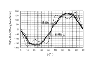
図14は、第1回転体2のコギングトルクTcog,harvと、上述した手法で最終的に得られた第2回転体4のコギングトルクTcog,genとを比較した図である。図14からわかるように、Tcog,harvとTcong,genはほぼ位相が逆になっており、この結果、全体的なコギングトルクを約90%削減することができた。
このように、本実施形態では、移動体5の移動または回転により移動体5の一側面に生じた渦電流による磁束と、移動体5の一側面に対向配置される第1回転体2の第1永久磁石2aの磁束との誘引力および反発力により、第1回転体2を回転させることができる。そして、本実施形態では、第1回転体2と一体に回転する第2回転体4を設け、第2回転体4の内周側に配置されるステータ6のティース6a先端と第2回転体4の内周面とのギャップを調整することで、第1回転体2の回転により生じるコギングトルクとほぼ逆位相のコギングトルクを第2回転体4にて発生させ、両者を相殺させることで、全体的なコギングトルクをゼロ近くにまで低減できる。これにより、移動体5が停止状態から徐々に移動または回転速度を上げる場合に、移動または回転速度が低い状態から第1回転体2を回転させることができ、移動体5の移動または回転による運動エネルギを効率よく抽出して、電気エネルギに変換でき、発電効率を向上できる。
(第2の実施形態)
上述した第1の実施形態では、第1回転体2と一体に回転する第2回転体4とステータ6とを用いて、第1回転体2に生じるコギングトルクを第2回転体4に生じるコギングトルクで相殺する例を説明したが、コギングトルクを相殺する具体的な手段は、第1の実施形態で説明したものに限定されない。
上述した第1の実施形態では、第1回転体2と一体に回転する第2回転体4とステータ6とを用いて、第1回転体2に生じるコギングトルクを第2回転体4に生じるコギングトルクで相殺する例を説明したが、コギングトルクを相殺する具体的な手段は、第1の実施形態で説明したものに限定されない。
第2の実施形態は、第2回転体4とステータ6を用いる代わりに、第1回転体2に一部が重なり合うように配置されるヨーク15を用いて、第1回転体2に生じるコギングトルクを相殺するものである。
図15Aと図15Bは第2の実施形態の概念を説明する図である。図15Aと図15Bは第1回転体2に対して移動体5とは点対称にヨーク15を配置する例を示している。図15Aの場合、移動体5と第1回転体2とが重なり合う領域では、N極よりもS極の方が面積的に大きく、反時計回りのコギングトルクが発生する。また、移動体5と第2回転体4とが重なり合う領域でも、N極よりもS極の方が面積的に大きいため、やはり反時計回りのコギングトルクが発生する。よって、ヨーク15がない場合よりも、さらに反時計回りのコギングトルクが大きくなる。この場合、ヨーク15によって第1回転体2のコギングトルクを相殺することはできない。
一方、図15Bの場合、移動体5と第1回転体2とが重なり合う領域では、N極とS極の面積がほぼ等しい。同様に、移動体5と第2回転体4とが重なり合う領域でも、N極とS極の面積がほぼ等しい。よって、ヨーク15の有無にかかわらず、図15Bの場合は、安定状態となり、第1回転体2は図15Bの状態で安定的に停止する。
このように、図15Aや図15Bのようにヨーク15を配置しても、第1回転体2のコギングトルクを相殺することはできず、ヨーク15を配置したことにより、却って第1回転体2は回転しにくくなってしまう。
一方、図16Aは、第1回転体2の移動体5と重なり合っている領域以外のほぼすべての領域でヨーク15と重なり合うようにした例を示している。ヨーク15の磁気特性すなわち透磁率が移動体5の磁気特性と同じで、かつ第1回転体2とヨーク15とのギャップが移動体5と第1回転体2とのギャップと等しい場合、第1回転体2の回転角度によって磁路の磁気抵抗が変化しなくなるため、第1回転体2に生じるコギングトルクが低減される。この例は、移動体5により第1回転体2に生じるコギングトルクを相殺するというよりは、第1回転体2にコギングトルク自体が発生しなくなる。
図16Bは、複数のヨーク15を用いて、移動体5により第1回転体2に生じるコギングトルクを相殺するように、各ヨーク15の配置場所を最適化する例を示している。図16Bでは、2つのヨーク15を用いているが、ヨーク15の個数、形状、透磁率等の磁気特性を最適化するのが望ましい。最適化には、第1の実施形態と同様にシミュレーションを用いればよい。
図16Aのヨーク15と図16Bのヨーク15がそれぞれコギングトルク相殺部8を構成している。図16Aのヨーク15は、上述したように、第1回転体2に発生するコギングトルク自体を低減するものであるが、ヨーク15がないとした場合の移動体5により第1回転体2に生じたコギングトルクを、ヨーク15を設けることで相殺して、結果的に、第1回転体2に発生するコギングトルク自体を低減している。したがって、図16Aのヨーク15も、コギングトルク相殺部8として機能している。
このように、第2の実施形態では、第1回転体2の第1永久磁石2aに少なくとも一部が重なり合うようにヨーク15を配置することで、第1回転体2にコギングトルク自体が発生しないようにしたり、あるいは移動体5により第1回転体2に生じるコギングトルクをヨーク15にて相殺することができる。
(第3の実施形態)
第3の実施形態は、第1回転体2とは別個の第2回転体4を設けて、第1回転体2と第2回転体4をともに、移動体5に近接配置するものである。
第3の実施形態は、第1回転体2とは別個の第2回転体4を設けて、第1回転体2と第2回転体4をともに、移動体5に近接配置するものである。
図17は第3の実施形態の概念を説明する図である。第3の実施形態によるコギングトルク相殺部8は、図17に示すように、第2回転体4と、同期回転機構とを有する。第2回転体4は、移動体5の一主面上に離隔して対向配置され、移動体5の回転または移動方向に応じて所定の回転軸回りに回転する第2永久磁石4aを有する。同期回転機構は、第1回転体2と第2回転体4とを同期して回転させる。同期回転機構の一例は、第1回転体2と第2回転体4の回転軸同士を掛け渡すタイミングベルト16である。同期回転機構は、必ずしもタイミングベルト16に限定されず、歯車などでもよい。
図17に示すように、第2回転体4は、第1回転体2と同様に、移動体5に重なり合うように配置されている。図17の例では、第1回転体2と移動体5とが重なり合う領域にはN極とS極が等面積ずつ含まれているのに対して、第2回転体4と移動体5とが重なり合う領域にはS極がN極よりも多く含まれている。すなわち、第1回転体2とは45°ずらして第2回転体4が配置されている。これにより、移動体5により第1回転体2に生じるコギングトルクを、移動体5により第2回転体4に生じるコギングトルクにて相殺することができる。
なお、第1回転体2と第2回転体4の径サイズや磁極数、磁気特性、移動体5とのギャップは、共通にするのが望ましい。また、図17では、並進運動する移動体5の例を示しているが、移動体5は回転運動をしてもよい。
このように、第3の実施形態では、第1回転体2と第2回転体4を移動体5に重ね合わせて配置し、かつ第1回転体2と第2回転体4とが一体に回転するようにし、かつ第1回転体2の磁極2bの配置方向と第2回転体4の磁極2bの配置方向とを互いに相違させるため、移動体5により第1回転体2に生じたコギングトルクを、第2回転体4に生じたコギングトルクにより相殺することができる。
(第4の実施形態)
上述した第1~第3の実施形態では、移動体5の一側面5cを第1回転体2の第1側面2dに対向配置する例を示したが、移動体5と第1回転体2との配置は上述したものに限定されない。上述したコギングトルク相殺部8は、移動体5の移動または回転により第1回転体2にコギングトルクが発生する種々の回転電機10に適用可能である。上述したコギングトルク相殺部8を取り付けることが可能な回転電機10の例としては、例えば以下のようなものがある。
上述した第1~第3の実施形態では、移動体5の一側面5cを第1回転体2の第1側面2dに対向配置する例を示したが、移動体5と第1回転体2との配置は上述したものに限定されない。上述したコギングトルク相殺部8は、移動体5の移動または回転により第1回転体2にコギングトルクが発生する種々の回転電機10に適用可能である。上述したコギングトルク相殺部8を取り付けることが可能な回転電機10の例としては、例えば以下のようなものがある。
図18Aはコギングトルク相殺部8を取り付けることが可能な回転電機10の第1例を示す図である。図18Aの非接触発電機1は、回転軸周りに回転する第1永久磁石2aと、2個のコイル7(第1コイル7aと第2コイル7b)と、ヨーク15とを備えている。
第1永久磁石2aは、回転または移動する移動体5の一主面5c上に離隔して対向配置され、移動体5の回転または移動方向に応じて回転する。第1永久磁石2aは、少なくとも2個の磁極2bを有し、各磁極2bの磁化方向は、第1永久磁石2aの外周面の法線方向である。
第1永久磁石2aの外周面2cは、移動体5の一主面5cから離隔して配置されており、第1永久磁石2aは、移動体5の一主面5cに接触することなく、回転自在とされている。図18Aの例では、2個のコイル7のうち一方の第1コイル7aは、移動体5の回転または移動方向に対して第1永久磁石2aの後方側に配置されている。2個のコイル7のうち他方の第2コイル7bは、移動体5の回転または移動方向に対して第1永久磁石2aの前方側に配置されている。第1および第2コイル7a,7bは、移動体5の一主面5c上に離隔して配置されている。
また、図18Aの例では、第1および第2コイル7a,7bの内部と上部には、コの字状のヨーク15が配置されている。ヨーク15と第1永久磁石2aとの間には隙間があり、同様に、第1永久磁石2aと第1および第2コイル7a,7bとの間にも隙間がある。これら隙間はエアギャップである。よって、第1永久磁石2aは、移動体5の一主面と、第1および第2コイル7a,7bと、ヨーク15とで囲まれる領域内で回転する。
図18Aの位置から時計回りまたは反時計回りに90°だけ第1永久磁石2aが回転した状態では、N極またはS極が最短距離で移動体5で対向することになり、最も磁路が短くなって安定した状態となる。よって、このように、図18Aの構造では、第1永久磁石2aの回転位置によって、コギングトルクが変化し、図1と同様に、移動体5が移動または回転を開始しても、なかなか第1永久磁石2aが回転しないという問題が起こりえる。よって、第1~第3の実施形態で説明した何らかのコギングトルク相殺部8を設けるのが望ましい。
なお、図18Aのコイル7は、第1永久磁石2aからの全磁束が集中する場所に配置すればよく、図18Aのコイル7の配置例は一例に過ぎない。また、ヨーク15の形状も図18Aに示すものに限定されない。
例えば、図18Bはコギングトルク相殺部8を取り付けることが可能な回転電機10の第2例を示す図であり、1個のコイル7で発電を行う例を示す図である。第1永久磁石2aの上方には、ヨーク15に巻回されたコイル7が配置されている。ヨーク15は第1永久磁石2aの上方から移動体5の移動方向の両側に延びて、第1永久磁石2aを取り囲むように配置されている。コイル7は、第1永久磁石2aからの磁束のほぼすべてを鎖交させるため、必ずしも複数のコイル7を設ける必要はない。なお、コイル7を配置する場所は、第1永久磁石2aからの全磁束が集中する場所(例えば、第1永久磁石2aのN極とS極の少なくとも一方の近傍)であればよい。
図18Bの第1永久磁石2aも、図18Aと同様に移動体5の移動によりコギングトルクが発生するため、やはり第1~第3の実施形態で説明した何らかのコギングトルク相殺部8を設けるのが望ましい。
本発明の態様は、上述した個々の実施形態に限定されるものではなく、当業者が想到しうる種々の変形も含むものであり、本発明の効果も上述した内容に限定されない。すなわち、特許請求の範囲に規定された内容およびその均等物から導き出される本発明の概念的な思想と趣旨を逸脱しない範囲で種々の追加、変更および部分的削除が可能である。
1 非接触発電機、2 第1回転体、2a 第1永久磁石、2b 磁極、3 ロータ、4 第2回転体、6 ステータ、7 コイル、8 コギングトルク相殺部、9a 回転軸、10 回転電機、11 運動エネルギ・ハーベスタ、12 発電機、13 駆動制御部
Claims (18)
- 回転または移動する導体である移動体の一主面上に離隔して対向配置され、前記移動体の回転または移動方向に応じて発生するローレンツ力によって所定の回転軸回りに回転する第1永久磁石を有する第1回転体と、
前記移動体と前記第1永久磁石との相対的な形状および位置関係により前記第1永久磁石に発生するコギングトルクを低減または相殺するコギングトルク相殺部と、を備える回転電機。 - 回転または移動する移動体の一主面上に離隔して対向配置され、前記移動体の回転または移動方向に応じて所定の回転軸回りに回転する第1永久磁石を有する第1回転体と、
前記移動体と前記第1永久磁石との相対的な形状および位置関係により前記第1永久磁石に発生するコギングトルクを低減または相殺するコギングトルク相殺部と、を備え、
前記第1回転体は、前記移動体の前記一主面上に前記第1永久磁石からの磁束の変化を妨げる方向に発生される渦電流に基づいて前記第1永久磁石に働く反発力および誘引力により、前記第1回転軸周りに回転し、
前記第1回転体の前記移動体に対向配置される前記一側面の表面速度は、対向配置される前記移動体の前記一主面の表面速度より遅い回転電機。 - 前記コギングトルク相殺部は、前記移動体と前記第1永久磁石との相対的な形状および位置関係により前記第1永久磁石に発生するコギングトルクの逆位相のコギングトルクを発生させる、請求項1または2に記載の回転電機。
- 前記コギングトルク相殺部は、前記第1永久磁石とは異なる第2永久磁石、または磁性体を用いて、前記コギングトルクを低減または相殺する、請求項1乃至3のいずれか一項に記載の回転電機。
- 前記コギングトルク相殺部は、
前記第1永久磁石とは異なる第2永久磁石を有し、前記第1回転体に同期して回転する第2回転体と、
前記第2永久磁石と磁気結合する第1磁性体と、を有する、請求項1乃至3のいずれか一項に記載の回転電機。 - 前記コギングトルク相殺部は、前記第2回転体と前記第1磁性体とのギャップを調整することにより、前記コギングトルクを低減する、請求項5に記載の回転電機。
- 前記第2回転体は、前記第1永久磁石とともに、前記回転軸回りに回転する円環部材であり、
前記第1磁性体は、前記円環部材の内周側に配置され、前記円環部材の内周面とのギャップを調整することにより、前記コギングトルクを低減する、請求項6に記載の回転電機。 - 前記第2永久磁石からの磁束が鎖交する位置に配置され、鎖交した磁束の変化量に応じた誘導電流を発生するコイルを備える、請求項5乃至7のいずれか一項に記載の回転電機。
- 前記コギングトルク相殺部は、前記第1永久磁石と磁気結合する第2磁性体を有し、
前記コギングトルク相殺部は、前記第1永久磁石と前記第2磁性体とが重なり合う領域を調整することにより、前記コギングトルクを低減する、請求項1乃至3のいずれか一項に記載の回転電機。 - 前記第2磁性体は、ヨークである、請求項9に記載の回転電機。
- 前記コギングトルク相殺部は、
前記移動体の一主面上に離隔して対向配置され、前記移動体の回転または移動方向に応じて所定の回転軸回りに回転する第2永久磁石を有する第2回転体と、
前記第1回転体と前記第2回転体とを同期させて回転させる同期回転機構と、を有し、 前記移動体と重なり合う前記第2永久磁石の磁極を、前記移動体と重なり合う前記第1永久磁石の磁極と相違させることで、前記コギングトルクを低減する、請求項1乃至3のいずれか一項に記載の回転電機。 - 回転または移動する導体である移動体の一主面上に離隔して対向配置され、前記移動体の回転または移動方向に応じて発生するローレンツ力によって所定の回転軸回りに回転する第1永久磁石を有する第1回転体と、
前記第1回転体の回転による運動エネルギを電気エネルギに変換する発電部と、を備え、
前記発電部は、前記移動体と前記第1永久磁石との相対的な形状および位置関係により前記第1永久磁石に発生するコギングトルクを低減または相殺するコギングトルク相殺部を有する非接触発電機。 - 回転または移動する移動体の一主面上に離隔して対向配置され、前記移動体の回転または移動方向に応じて所定の回転軸回りに回転する第1永久磁石を有する第1回転体と、
前記第1回転体の回転による運動エネルギを電気エネルギに変換する発電部と、を備え、
前記発電部は、前記移動体と前記第1永久磁石との相対的な形状および位置関係により前記第1永久磁石に発生するコギングトルクを低減または相殺するコギングトルク相殺部を有し、
前記第1回転体は、前記移動体の前記一主面上に前記第1永久磁石からの磁束の変化を妨げる方向に発生される渦電流に基づいて前記第1永久磁石に働く反発力および誘引力により、前記第1回転軸周りに回転し、
前記第1回転体の前記移動体に対向配置される前記一側面の表面速度は、対向配置される前記移動体の前記一主面の表面速度より遅い、非接触発電機。 - 前記コギングトルク相殺部は、前記第1永久磁石とは別個に前記発電部が有する第2永久磁石を用いて、前記コギングトルクを低減または相殺する、請求項12または13に記載の非接触発電機。
- 前記コギングトルク相殺部は、
前記第1永久磁石とは異なる第2永久磁石を有し、前記第1回転体に同期して回転する第2回転体と、
前記第2永久磁石と磁気結合する第1磁性体と、を有し、
前記発電部は、前記第2永久磁石からの磁束が鎖交する位置に配置され、鎖交した磁束の変化量に応じた誘導電流を発生するコイルを有する、請求項12乃至14のいずれか一項に記載の非接触発電機。 - 前記コギングトルク相殺部は、前記第1永久磁石と磁気結合する第2磁性体を有し、
前記コギングトルク相殺部は、前記第1永久磁石と前記第2磁性体とが重なり合う領域を調整することにより、前記コギングトルクを低減する、請求項12乃至14のいずれか一項に記載の非接触発電機。 - 前記コギングトルク相殺部は、
前記移動体の一主面上に離隔して対向配置され、前記移動体の回転または移動方向に応じて所定の回転軸回りに回転する第2永久磁石を有する第2回転体と、
前記第1回転体と前記第2回転体とを同期させて回転させる同期回転機構と、を有し、 前記移動体と重なり合う前記第2永久磁石の磁極を、前記移動体と重なり合う前記第1永久磁石の磁極と相違させることで、前記コギングトルクを低減する、請求項12乃至14のいずれか一項に記載の非接触発電機。 - 前記発電部は、前記第1永久磁石からの磁束が鎖交する位置に配置され、鎖交した磁束の変化量に応じた誘導電流を発生するコイルを有する、請求項12乃至17のいずれか一項に記載の非接触発電機。
Priority Applications (3)
| Application Number | Priority Date | Filing Date | Title |
|---|---|---|---|
| CN201780044511.5A CN109478838B (zh) | 2016-07-20 | 2017-07-19 | 旋转电机和非接触发电机 |
| JP2018528843A JP6685399B2 (ja) | 2016-07-20 | 2017-07-19 | 回転電機および非接触発電機 |
| EP17831061.1A EP3490121B1 (en) | 2016-07-20 | 2017-07-19 | Rotary motor and non-contact generator |
Applications Claiming Priority (2)
| Application Number | Priority Date | Filing Date | Title |
|---|---|---|---|
| JP2016142820 | 2016-07-20 | ||
| JP2016-142820 | 2016-07-20 |
Publications (1)
| Publication Number | Publication Date |
|---|---|
| WO2018016545A1 true WO2018016545A1 (ja) | 2018-01-25 |
Family
ID=60992570
Family Applications (1)
| Application Number | Title | Priority Date | Filing Date |
|---|---|---|---|
| PCT/JP2017/026167 Ceased WO2018016545A1 (ja) | 2016-07-20 | 2017-07-19 | 回転電機および非接触発電機 |
Country Status (4)
| Country | Link |
|---|---|
| EP (1) | EP3490121B1 (ja) |
| JP (1) | JP6685399B2 (ja) |
| CN (1) | CN109478838B (ja) |
| WO (1) | WO2018016545A1 (ja) |
Cited By (1)
| Publication number | Priority date | Publication date | Assignee | Title |
|---|---|---|---|---|
| JP2024019784A (ja) * | 2022-08-01 | 2024-02-14 | 株式会社東京理工舎 | ローラコンベアシステム |
Citations (3)
| Publication number | Priority date | Publication date | Assignee | Title |
|---|---|---|---|---|
| JP2011254618A (ja) * | 2010-06-02 | 2011-12-15 | Fuji Electric Co Ltd | アキシャルギャップモータ |
| WO2012101938A1 (ja) * | 2011-01-26 | 2012-08-02 | 株式会社日立産機システム | モータユニットおよびこれを用いた回転電機、回転電機装置 |
| JP2014073076A (ja) * | 2012-09-27 | 2014-04-21 | Sunrising Eco-Friendly Technology Co Ltd | 磁気誘導式回転子部材、非接触式発電装置及び自転車用非接触式発光装置 |
Family Cites Families (3)
| Publication number | Priority date | Publication date | Assignee | Title |
|---|---|---|---|---|
| WO2013106919A1 (en) * | 2012-01-20 | 2013-07-25 | Idénergie Inc. | Electric apparatus using eddy current generation for transmitting torque between two adjacent rotors |
| CN104734446A (zh) * | 2015-04-09 | 2015-06-24 | 莱克电气股份有限公司 | 一种内置式永磁同步电机 |
| CN105763009B (zh) * | 2016-04-20 | 2018-02-27 | 山东大学 | 混合磁路低谐波多定子弱磁扩速永磁同步电机及其方法 |
-
2017
- 2017-07-19 WO PCT/JP2017/026167 patent/WO2018016545A1/ja not_active Ceased
- 2017-07-19 JP JP2018528843A patent/JP6685399B2/ja active Active
- 2017-07-19 EP EP17831061.1A patent/EP3490121B1/en active Active
- 2017-07-19 CN CN201780044511.5A patent/CN109478838B/zh active Active
Patent Citations (3)
| Publication number | Priority date | Publication date | Assignee | Title |
|---|---|---|---|---|
| JP2011254618A (ja) * | 2010-06-02 | 2011-12-15 | Fuji Electric Co Ltd | アキシャルギャップモータ |
| WO2012101938A1 (ja) * | 2011-01-26 | 2012-08-02 | 株式会社日立産機システム | モータユニットおよびこれを用いた回転電機、回転電機装置 |
| JP2014073076A (ja) * | 2012-09-27 | 2014-04-21 | Sunrising Eco-Friendly Technology Co Ltd | 磁気誘導式回転子部材、非接触式発電装置及び自転車用非接触式発光装置 |
Non-Patent Citations (1)
| Title |
|---|
| See also references of EP3490121A4 * |
Cited By (1)
| Publication number | Priority date | Publication date | Assignee | Title |
|---|---|---|---|---|
| JP2024019784A (ja) * | 2022-08-01 | 2024-02-14 | 株式会社東京理工舎 | ローラコンベアシステム |
Also Published As
| Publication number | Publication date |
|---|---|
| EP3490121A1 (en) | 2019-05-29 |
| EP3490121A4 (en) | 2020-02-19 |
| CN109478838A (zh) | 2019-03-15 |
| CN109478838B (zh) | 2021-04-09 |
| JP6685399B2 (ja) | 2020-04-22 |
| JPWO2018016545A1 (ja) | 2019-04-04 |
| EP3490121B1 (en) | 2021-09-29 |
Similar Documents
| Publication | Publication Date | Title |
|---|---|---|
| JP6781489B2 (ja) | 電磁装置 | |
| JP6639810B2 (ja) | 回転電機および非接触発電機 | |
| JP5857627B2 (ja) | 電動回転機 | |
| JP2013094020A (ja) | 電動回転機 | |
| JP2013038944A (ja) | モータ | |
| US20100308674A1 (en) | Magnetic machine | |
| Sakaidani et al. | Experimental verification of feedback control of a 2-DOF spherical actuator | |
| WO2016199845A1 (ja) | 回転電機および非接触発電機 | |
| JP2015104180A (ja) | 回転電機の回転子 | |
| JP2016536952A (ja) | ハイブリッド車のための改良されたスイッチトリラクタンスモータ及びスイッチトリラクタンス装置 | |
| MX2014015793A (es) | Nuevo dispositivo. | |
| JP2012244874A (ja) | 回転電機 | |
| JP2016025700A (ja) | 磁気ねじアクチュエータ | |
| JP6685399B2 (ja) | 回転電機および非接触発電機 | |
| Kang et al. | Method of current compensation for reducing error of holding torque of permanent-magnet spherical wheel motor | |
| JP2011182638A (ja) | 磁気変速機組立体 | |
| WO2015136758A1 (ja) | リニアモータ | |
| JP6332094B2 (ja) | ロータ、電動モータ | |
| CN110754038B (zh) | 电动机控制装置以及电动机系统 | |
| Li et al. | Halbach array magnet and its application to PM spherical motor | |
| Takahara et al. | Proposal of 3-degree-of-freedom spherical actuator with auxiliary poles | |
| JP5708566B2 (ja) | 電磁カップリング | |
| RU81395U1 (ru) | Магнитоэлектрический генератор | |
| Zhou et al. | Structural design and FEA of a new type of multi-DOF spherical induction motor without output shaft | |
| JP7665489B2 (ja) | 回転電機 |
Legal Events
| Date | Code | Title | Description |
|---|---|---|---|
| 121 | Ep: the epo has been informed by wipo that ep was designated in this application |
Ref document number: 17831061 Country of ref document: EP Kind code of ref document: A1 |
|
| ENP | Entry into the national phase |
Ref document number: 2018528843 Country of ref document: JP Kind code of ref document: A |
|
| NENP | Non-entry into the national phase |
Ref country code: DE |
|
| ENP | Entry into the national phase |
Ref document number: 2017831061 Country of ref document: EP Effective date: 20190220 |