WO2018016545A1 - Moteur rotatif et générateur sans contact - Google Patents
Moteur rotatif et générateur sans contact Download PDFInfo
- Publication number
- WO2018016545A1 WO2018016545A1 PCT/JP2017/026167 JP2017026167W WO2018016545A1 WO 2018016545 A1 WO2018016545 A1 WO 2018016545A1 JP 2017026167 W JP2017026167 W JP 2017026167W WO 2018016545 A1 WO2018016545 A1 WO 2018016545A1
- Authority
- WO
- WIPO (PCT)
- Prior art keywords
- permanent magnet
- cogging torque
- moving body
- rotating body
- rotating
- Prior art date
- Legal status (The legal status is an assumption and is not a legal conclusion. Google has not performed a legal analysis and makes no representation as to the accuracy of the status listed.)
- Ceased
Links
Images



Classifications
-
- H—ELECTRICITY
- H02—GENERATION; CONVERSION OR DISTRIBUTION OF ELECTRIC POWER
- H02K—DYNAMO-ELECTRIC MACHINES
- H02K7/00—Arrangements for handling mechanical energy structurally associated with dynamo-electric machines, e.g. structural association with mechanical driving motors or auxiliary dynamo-electric machines
- H02K7/10—Structural association with clutches, brakes, gears, pulleys or mechanical starters
- H02K7/104—Structural association with clutches, brakes, gears, pulleys or mechanical starters with eddy-current brakes
-
- H—ELECTRICITY
- H02—GENERATION; CONVERSION OR DISTRIBUTION OF ELECTRIC POWER
- H02K—DYNAMO-ELECTRIC MACHINES
- H02K49/00—Dynamo-electric clutches; Dynamo-electric brakes
- H02K49/02—Dynamo-electric clutches; Dynamo-electric brakes of the asynchronous induction type
- H02K49/04—Dynamo-electric clutches; Dynamo-electric brakes of the asynchronous induction type of the eddy-current hysteresis type
- H02K49/046—Dynamo-electric clutches; Dynamo-electric brakes of the asynchronous induction type of the eddy-current hysteresis type with an axial airgap
-
- H—ELECTRICITY
- H02—GENERATION; CONVERSION OR DISTRIBUTION OF ELECTRIC POWER
- H02K—DYNAMO-ELECTRIC MACHINES
- H02K7/00—Arrangements for handling mechanical energy structurally associated with dynamo-electric machines, e.g. structural association with mechanical driving motors or auxiliary dynamo-electric machines
- H02K7/18—Structural association of electric generators with mechanical driving motors, e.g. with turbines
- H02K7/1807—Rotary generators
- H02K7/1846—Rotary generators structurally associated with wheels or associated parts
-
- B—PERFORMING OPERATIONS; TRANSPORTING
- B62—LAND VEHICLES FOR TRAVELLING OTHERWISE THAN ON RAILS
- B62J—CYCLE SADDLES OR SEATS; AUXILIARY DEVICES OR ACCESSORIES SPECIALLY ADAPTED TO CYCLES AND NOT OTHERWISE PROVIDED FOR, e.g. ARTICLE CARRIERS OR CYCLE PROTECTORS
- B62J6/00—Arrangement of optical signalling or lighting devices on cycles; Mounting or supporting thereof; Circuits therefor
- B62J6/06—Arrangement of lighting dynamos or drives therefor
-
- H—ELECTRICITY
- H02—GENERATION; CONVERSION OR DISTRIBUTION OF ELECTRIC POWER
- H02K—DYNAMO-ELECTRIC MACHINES
- H02K21/00—Synchronous motors having permanent magnets; Synchronous generators having permanent magnets
- H02K21/12—Synchronous motors having permanent magnets; Synchronous generators having permanent magnets with stationary armatures and rotating magnets
- H02K21/14—Synchronous motors having permanent magnets; Synchronous generators having permanent magnets with stationary armatures and rotating magnets with magnets rotating within the armatures
-
- H—ELECTRICITY
- H02—GENERATION; CONVERSION OR DISTRIBUTION OF ELECTRIC POWER
- H02K—DYNAMO-ELECTRIC MACHINES
- H02K2201/00—Specific aspects not provided for in the other groups of this subclass relating to the magnetic circuits
- H02K2201/03—Machines characterised by aspects of the air-gap between rotor and stator
Definitions
- the present invention relates to a rotating electrical machine that rotates in a non-contact manner and a non-contact generator that generates power in a non-contact manner.
- US Patent Publication No. 2014/0132155 discloses a dynamo for a bicycle that generates power without contact.
- the outer peripheral surface of an annular permanent magnet that rotates around a rotation axis extending in a direction orthogonal to the rotation axis of the bicycle wheel is separated from one side surface that is continuous with the outer peripheral surface of the wheel. It is arranged.
- a permanent magnet has a plurality of magnetic poles arranged in the circumferential direction, and the magnetization directions of the adjacent magnetic poles are reversed. For example, when the wheel rotates with the N pole of the permanent magnet opposed to one side of the wheel, an eddy current is generated on one side of the wheel in a direction that prevents a change in magnetic flux from the permanent magnet.
- the permanent magnet rotates in the rotation direction of the wheel by the repulsive force and the attractive force of the magnetic flux caused by the eddy current and the magnetic flux from the permanent magnet.
- the induction power can be taken out from the coil.
- a single-phase coil is wound around a permanent magnet.
- a single-phase coil cannot effectively use the magnetic flux of a portion of the permanent magnet where the coil is not wound. Can not be increased.
- the direction of the polarity of the permanent magnet around the coil is symmetric about the rotation axis, the total amount of magnetic flux that interlinks the coil always cancels out. .
- the present invention has been made in view of the above-described problems, and an object of the present invention is to provide a rotating electrical machine and a non-contact power generator that have good magnetic efficiency, little leakage of magnetic flux, and have taken measures against cogging torque. It is.
- the moving body which is a rotating or moving conductor, is disposed oppositely on one main surface of the moving body, and is generated according to the rotation or moving direction of the moving body.
- a first rotating body having a first permanent magnet that rotates about a predetermined rotation axis by a Lorentz force
- a rotating electrical machine including a cogging torque canceling unit that reduces or cancels a cogging torque generated in the first permanent magnet by a relative shape and positional relationship between the moving body and the first permanent magnet.
- a first permanent that is arranged oppositely on one main surface of a rotating or moving moving body and rotates about a predetermined rotation axis according to the rotation or moving direction of the moving body.
- a first rotating body having a magnet;
- a cogging torque canceling unit that reduces or cancels the cogging torque generated in the first permanent magnet due to the relative shape and positional relationship between the moving body and the first permanent magnet;
- the first rotating body has a repulsive force and an attractive force acting on the first permanent magnet based on an eddy current generated in a direction that prevents a change in magnetic flux from the first permanent magnet on the one main surface of the moving body.
- a rotating electrical machine is provided in which the surface speed of the one side surface of the first rotating body arranged to face the moving body is slower than the surface speed of the one main surface of the moving body arranged to face the first rotating body.
- the cogging torque canceling unit may generate a cogging torque having a phase opposite to that of the cogging torque generated in the first permanent magnet according to a relative shape and positional relationship between the moving body and the first permanent magnet.
- the cogging torque canceling unit may reduce or cancel the cogging torque using a second permanent magnet different from the first permanent magnet or a magnetic material.
- the cogging torque canceling unit is A second rotating body having a second permanent magnet different from the first permanent magnet and rotating in synchronization with the first rotating body; A first magnetic body that is magnetically coupled to the second permanent magnet.
- the cogging torque canceling unit may reduce the cogging torque by adjusting a gap between the second rotating body and the first magnetic body.
- the second rotating body may be an annular member that rotates around the rotation axis together with the first permanent magnet,
- the first magnetic body may be disposed on an inner peripheral side of the annular member, and the cogging torque may be reduced by adjusting a gap with the inner peripheral surface of the annular member.
- a coil may be provided that is arranged at a position where the magnetic flux from the second permanent magnet is linked and generates an induced current corresponding to the amount of change in the linked magnetic flux.
- the cogging torque canceling unit may include a second magnetic body that is magnetically coupled to the first permanent magnet, The cogging torque canceling unit may reduce the cogging torque by adjusting a region where the first permanent magnet and the second magnetic body overlap each other.
- the second magnetic body may be a yoke.
- the cogging torque canceling unit is A second rotating body having a second permanent magnet that is disposed oppositely on one main surface of the moving body and rotates around a predetermined rotation axis according to the rotation or moving direction of the moving body; A synchronous rotating mechanism that rotates the first rotating body and the second rotating body in synchronization with each other; The cogging torque may be reduced by making the magnetic pole of the second permanent magnet overlapping the moving body different from the magnetic pole of the first permanent magnet overlapping the moving body.
- a rotating body that is a rotating or moving conductor is disposed on one main surface of the moving body so as to be separated from the main surface, and a predetermined rotation is generated by a Lorentz force generated according to the rotation or moving direction of the moving body.
- a first rotating body having a first permanent magnet rotating about an axis;
- a power generation unit that converts kinetic energy generated by the rotation of the first rotating body into electrical energy,
- the non-contact power generator includes a cogging torque canceling unit that reduces or cancels cogging torque generated in the first permanent magnet according to a relative shape and positional relationship between the moving body and the first permanent magnet.
- a first permanent that is arranged oppositely on one main surface of a rotating or moving moving body and rotates about a predetermined rotation axis according to the rotation or moving direction of the moving body.
- a first rotating body having a magnet;
- a power generation unit that converts kinetic energy generated by the rotation of the first rotating body into electrical energy,
- the power generation unit includes a cogging torque canceling unit that reduces or cancels the cogging torque generated in the first permanent magnet due to the relative shape and positional relationship between the moving body and the first permanent magnet,
- the first rotating body has a repulsive force and an attractive force acting on the first permanent magnet based on an eddy current generated in a direction that prevents a change in magnetic flux from the first permanent magnet on the one main surface of the moving body.
- a non-contact power generator is provided in which a surface speed of the one side surface of the first rotating body arranged to face the moving body is slower than a surface speed of the one main surface of the moving body arranged to face the first rotating body.
- the cogging torque canceling unit may reduce or cancel the cogging torque by using a second permanent magnet included in the power generation unit separately from the first permanent magnet.
- the cogging torque canceling unit is A second rotating body having a second permanent magnet different from the first permanent magnet and rotating in synchronization with the first rotating body; A first magnetic body magnetically coupled to the second permanent magnet,
- the power generation unit may include a coil that is arranged at a position where the magnetic flux from the second permanent magnet is linked and generates an induced current according to a change amount of the linked magnetic flux.
- the cogging torque canceling unit has a second magnetic body magnetically coupled to the first permanent magnet,
- the cogging torque canceling unit may reduce the cogging torque by adjusting a region where the first permanent magnet and the second magnetic body overlap each other.
- the cogging torque canceling unit is A second rotating body having a second permanent magnet that is disposed oppositely on one main surface of the moving body and rotates around a predetermined rotation axis according to the rotation or moving direction of the moving body; A synchronous rotating mechanism that rotates the first rotating body and the second rotating body synchronously, and the magnetic pole of the second permanent magnet that overlaps the moving body is the first permanent that overlaps the moving body.
- the cogging torque may be reduced by making it different from the magnetic pole of the magnet.
- the power generation unit may include a coil that is arranged at a position where the magnetic flux from the first permanent magnet is linked and generates an induced current according to the amount of change in the linked magnetic flux.
- Sectional drawing of the non-contact generator of FIG. The external view of the 1st rotary body which consists of a 1st permanent magnet.
- the top view which shows the structure before optimizing the gap of a stator and a 2nd rotary body.
- the top view which shows the structure after optimizing a gap.
- the flowchart which shows the algorithm which optimizes the gap of the teeth tip of a stator and a 2nd rotary body.
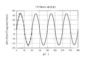
- the figure which compared the cogging torque of the 1st rotary body with the cogging torque of the 2nd rotary body finally obtained.
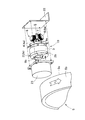
- FIG. 1 is an exploded perspective view of a non-contact generator 1 incorporating a rotating electrical machine 10 according to the first embodiment
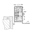
- FIG. 2 is a cross-sectional view of the non-contact generator 1 of FIG.
- the non-contact generator 1 includes a first rotating body 2, a rotor 3, a second rotating body 4, a stator 6, and a first permanent magnet 2a.
- the first rotating body 2, the rotor 3 and the second rotating body 4 constitute a rotating electrical machine 10, and the second rotating body 4 and the stator 6 constitute a cogging torque canceling unit 8.
- the first rotating body 2 is rotatable around a predetermined rotating shaft 9a.
- a bearing 9b is disposed around the rotation shaft 9a, and the rotation shaft 9a rotates clockwise or counterclockwise according to the rotation direction of the moving body 5.
- the first permanent magnet 2a of the first rotating body 2 has a plurality of magnetic poles 2b arranged circumferentially.
- FIG. 1 shows an example in which the first permanent magnet 2a has four magnetic poles 2b, the number of the magnetic poles 2b may be two or more and is not limited to four.
- the first rotating body 2 is disposed oppositely on one main surface of the moving body 5 that rotates or moves.
- the example of FIGS. 1 and 2 shows an example in which the moving body 5 rotates about its central axis, the moving body 5 may perform a translational motion.
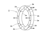
- FIG. 3 is an external view of the first rotating body 2 including the first permanent magnet 2a.
- the rotating shaft 9a of the first rotating body 2 and the rotating shaft of the moving body 5 are arranged in parallel, and at least a part of the first side surface 2d connected to the outer peripheral surface 2c of the first rotating body 2 is the moving body 5. Is disposed opposite to one side surface 5c continuous with the outer peripheral surface 5b. More specifically, two or more magnetic poles 2b among the plurality of magnetic poles 2b of the first rotating body 2 are arranged to face one side surface 5c of the moving body 5. Thereby, as will be described later, the amount of magnetic coupling between the first rotating body 2 and the moving body 5 can be increased, and the eddy current generated on the one side surface 5c of the moving body 5 can be increased.
- the moving body 5 is, for example, a vehicle wheel or a wheel.
- the moving body 5 generates an eddy current on the one side surface 5 c disposed to face the first rotating body 2.
- at least one side surface 5c of the moving body 5 needs to be formed of a conductive material such as metal.
- an eddy current is generated on one side surface 5c of the moving body 5 by the magnetic flux from each magnetic pole 2b of the first permanent magnet 2a constituting the first rotating body 2. Therefore, the interval between the first side surface 2d of the first rotating body 2 and the one side surface 5c of the moving body 5 is within a range in which the magnetic flux from each magnetic pole 2b of the first rotating body 2 can reach the moving body 5. Limited.
- Each magnetic pole 2b of the first permanent magnet 2a is magnetized in a direction toward the one side surface 5c of the opposed moving body 5 or in the opposite direction. Further, the magnetization directions of the adjacent magnetic poles 2b of the first permanent magnet 2a are opposite. In FIG. 3, the magnetization direction of each magnetic pole 2b of the first permanent magnet 2a is indicated by an arrow. As shown in FIG. 3, N poles and S poles are alternately arranged in a circumferential manner on the first side surface 2 d of the first rotating body 2. Further, the side surface 2e of the first rotating body 2 opposite to the first side surface 2d facing the moving body 5 has a polarity opposite to that of the one side surface.
- the first rotating body 2, the rotor 3, the second rotating body 4, and the stator 6 are covered with a cover 21.
- the stator 6 is fixed on the mounting plate 22.
- the cover 21 and the mounting plate 22 are not essential components, and their shapes and sizes are also arbitrary.
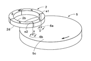
- FIG. 4 is a diagram for explaining the principle of rotation of the first rotating body 2 by eddy currents 5d and 5e generated on one side surface 5c of the moving body 5.
- FIG. 4 Of the plurality of magnetic poles 2b arranged circumferentially on the first side surface 2d of the first rotating body 2, the magnetic flux from the magnetic pole 2b arranged to face the one side surface 5c of the moving body 5 is in the direction of the one side surface 5c of the moving body 5 Propagate to.
- An air gap is formed between the first side surface 2d of the first rotating body 2 and one side surface 5c of the moving body 5, and the magnetic pole 2b from the first rotating body 2 propagates through the air gap.
- the magnetic flux from the edge e1 at the front of the N pole in the rotational direction reaches the one side surface 5c portion of the moving body 5.
- the direction of the eddy current 5d generated is different from the direction of the eddy current 5e generated at the side surface 5c of the moving body 5 where the magnetic flux from the edge e2 behind the N pole rotation direction arrives.
- the eddy current 5e generated by the magnetic flux from the edge e2 behind the rotation direction of the N pole flows in a direction to generate a magnetic flux in a direction opposite to the magnetic flux from the N pole.
- the eddy current 5d generated in one side surface 5c portion of the moving body 5 to which the magnetic flux from the edge e1 in the rotation direction of the N pole arrives flows in a direction in which the magnetic flux in the same direction as the magnetic flux from the N pole is generated. Any of the eddy currents 5d and 5e flows in a direction that prevents a change in magnetic flux from the first rotating body 2 accompanying the rotation of the moving body 5.
- the first rotating body 2 rotates at a surface speed slower than the surface speed of the one side surface 5c of the opposed moving body 5 so as to follow the moving surface of the one side surface 5c of the facing moving body 5.
- the principle of the rotation of the first rotating body 2 described above can also be explained by a repulsive force and an attractive force due to Lorentz force.
- the direction of the current is opposite to that of the current 5e, and a current in a constant direction always flows directly below the N pole.
- the currents caused by these eddy currents 5d and 5e receive a Lorentz force in the direction opposite to the rotation direction of the moving body 5 when the moving body 5 rotates in the direction of the arrow in FIG. Therefore, the first rotating body 2 that receives the magnetic flux generated by these eddy currents 5 d and 5 e rotates in response to the repulsive force and the attractive force of the Lorentz force in the rotating direction of the moving body 5.
- the first rotating body 2 and the moving body 5 move in the same direction on the opposing surfaces thereof. Therefore, as shown in FIG. 4, when the first rotating body 2 is disposed opposite to the rotational axis of the moving body 5, the rotating direction of the first rotating body 2 is opposite to the rotating direction of the moving body 5. become.
- the first side surface of the rotor 3 is joined to the second side surface opposite to the first side surface 2d of the first rotating body 2, and the second side surface opposite to the first side surface.
- the 1st side surface of the 2nd rotary body 4 is joined to.
- the first rotating body 2, the rotor 3 and the second rotating body 4 are all rotatable around a common rotating shaft 9a.
- the first rotating body 2, the rotor 3, and the second rotating body 4 rotate integrally around the rotation shaft 9a.
- the diameter size of the 1st rotary body 2, the rotor 3, and the 2nd rotary body 4 may be the same, or may each differ. In the example of FIG. 2, the diameter size of the first rotating body 2 and the rotor 3 is made substantially the same, and the diameter size of the second rotating body 4 is made smaller than that of the rotor 3. Thereby, the 2nd rotary body 4 can be accommodated inside the inner peripheral surface of the rotor 3.
- the second rotating body 4 has an annular second permanent magnet 4a in which a plurality of magnetic poles 2b are arranged in the circumferential direction.
- the number of magnetic poles of the second permanent magnet 4a is not particularly limited.
- a stator 6 is disposed inside the inner peripheral surface of the annular second permanent magnet 4a.
- the stator 6 is fixed and has a plurality of teeth 6a extending radially from the center of the second permanent magnet 4a.
- the stator 6 is made of a magnetic material, and a coil 7 is wound around each tooth 6a. These coils 7 are arranged at positions where the magnetic flux from the second permanent magnet 4a is linked, and generate an induced current corresponding to the amount of change in the linked magnetic flux.
- a non-uniform gap is provided between the tip position of the radially extending teeth 6a and the inner peripheral surface of the second permanent magnet 4a.
- FIG. 5 is a block diagram of the non-contact generator 1 according to the present embodiment.
- the non-contact generator 1 according to this embodiment includes a kinetic energy harvester (KEH: KineticKEnergy Harvester) 11, a generator 12, a drive control unit 13, and a cogging torque canceling unit 8. I have.
- KH KineticKEnergy Harvester
- the kinetic energy harvester 11 includes a moving body 5 and a first rotating body 2.
- the kinetic energy harvester 11 generates an eddy current on one side of the moving body 5 by the movement or rotation of the moving body 5, and the attractive force between the magnetic flux generated by this eddy current and the first permanent magnet 2 a of the first rotating body 2.
- the first rotating body 2 is rotated by the repulsive force.
- the kinetic energy harvester 11 has a function of converting the kinetic energy caused by the movement or rotation of the moving body 5 into the rotational energy of the first rotating body 2.
- the generator 12 includes the second rotating body 4 and the coil 7 of the stator 6.
- the second rotating body 4 When the first rotating body 2 rotates due to the movement or rotation of the moving body 5, the second rotating body 4 also rotates together with the first rotating body 2. Thereby, an alternating magnetic flux whose direction changes periodically is linked to the coil 7 wound around the tooth 6 a of the stator 6, and an induced current is generated in the coil 7.
- the generator 12 has a function of converting the rotational energy of the first rotating body 2 into an induced current flowing in the coil 7 via the second rotating body 4.
- the drive control unit 13 converts the induced current generated in the coil 7 into, for example, an AC voltage or a DC voltage, and performs control for driving various loads 14.
- the load 14 is a motor, an actuator, various sensors, etc., and the specific type is not ask
- the drive control unit 13 may store electric power corresponding to the induced current generated by the generator 12 in a capacitor (not shown).
- the cogging torque canceling unit 8 includes the second permanent magnet 4 a and the stator 6.
- the cogging torque canceling unit 8 cancels at least a part of the cogging torque generated in the first permanent magnet 2a by the relative shape and positional relationship between the moving body 5 and the first permanent magnet 2a. More specifically, the cogging torque canceling unit 8 adjusts the gap between the tip position of the teeth 6a extending radially of the stator 6 and the inner peripheral surface of the second permanent magnet 4a, for example, thereby adjusting the first permanent. At least a part of the cogging torque generated in the magnet 2a is canceled.
- cogging torque canceling unit 8 cancels the cogging torque generated in the first permanent magnet 2a is not limited to the above-described gap adjustment, as will be described later.
- cancellation means that the cogging torque generated in the first permanent magnet 2a by the moving body 5 is canceled by the cogging torque generated in another member, and the cogging torque generated in the first permanent magnet 2a. Including the case of reducing itself.
- the cogging torque is generated by the relative shape and positional relationship between the moving body 5 and the first permanent magnet 2a of the first rotating body 2, and is an eddy current generated on one side of the moving body 5. It has nothing to do with it.
- the cogging torque is constant regardless of the moving speed of the moving body 5.
- the cogging torque is generated due to non-uniformity of the attractive force between the moving body 5 that is a magnetic body and the first magnet of the first rotating body 2. That is, since the first permanent magnet 2a of the first rotating body 2 has a plurality of magnetic poles 2b in the circumferential direction, the strength of the attracting force to the moving body 5 varies depending on the rotation angle and rotation position of the first rotating body 2, This causes cogging torque.
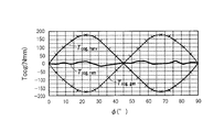
- FIG. 6 is a graph showing the cogging torque for one turn of the first rotating body 2.
- the horizontal axis of FIG. 6 is the rotation angle ⁇ (°) of the first rotating body 2, and the vertical axis is the cogging torque Tcog, harv (Nmm).
- the graph of FIG. 6 shows an example in which the first permanent magnet 2a of the first rotating body 2 has four magnetic poles 2b having the same length in the circumferential direction.
- the cogging torque has a waveform of one cycle every 90 °, and the ratio of the N pole and the S pole in a region where one side surface of the moving body 5 and one side surface of the first rotating body 2 overlap. When the values are equal, the cogging torque becomes zero.
- the absolute value of the cogging torque is maximized when the ratio of the N pole is maximum or the ratio of the S pole is maximum in a region where one side of the moving body 5 and one side of the first rotating body 2 overlap.
- the cogging torque is generated not only in the first rotating body 2 but also in the second rotating body 4.
- the cogging torque of the second rotating body 4 varies depending on the relative shape and positional relationship with the stator 6.
- the cogging torque canceling unit 8 ideally uses the cogging torque Tcog, harv ( ⁇ ) of the first rotating body 2 and the cogging torque Tcog, gen ( ⁇ of the second rotating body 4 as shown in the equation (1). ) To completely cancel out to zero.
- the cogging torque Tcog ( ⁇ ) is Fourier expanded as shown in the equation (2).
- Tcog ( ⁇ ) c 1 sin (4 ⁇ ) + d 1 cos (4 ⁇ ) + c 2 sin (8 ⁇ ) + d 2 cos (8 ⁇ ) + ... (2)
- ⁇ in equation (2) is the rotation angle of the rotor 3.
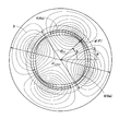
- FIG. 7 is a diagram showing a result of a two-dimensional FEM simulation of the generator 12 including the second rotating body 4 and the stator 6.
- the gap between the teeth 6a of the stator 6 and the second rotating body 4 is adjusted in order to cause the second rotating body 4 to generate a cogging torque that can cancel the cogging torque generated in the first rotating body 2.
- An example is shown.
- ⁇ is an angle from a predetermined reference direction of the stator 6 as shown in FIG.
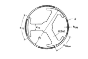
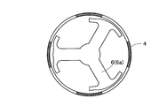
- FIG. 8A is a plan view showing the structure before optimizing the gap between the stator 6 and the second rotating body 4, and FIG. 8B is a plan view showing the structure after optimizing the gap.
- 8A and 8B show the structure of the stator 6 obtained by simulation.
- the shape of the tip position of the teeth 6a of the stator 6 in FIG. 8B is different from that in FIG. 8A, and thus the gap is optimized.
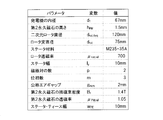
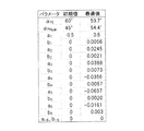
- the various parameters set when generating the structure of FIG. 8B by simulation are as shown in FIG.
- the width ⁇ FE of the teeth 6a of the stator 6 and the distance ⁇ PMgap between the magnetic poles 2b of the second permanent magnet 4a were used as parameters for calculating the structure of FIG. 8B.
- FIG. 10 is a flowchart showing an algorithm for optimizing the gap between the tip of the teeth 6a of the stator 6 and the second rotating body 4.
- the geometric parameters (geometry parameters) of the generator 12 having a preselected shape are initialized (step S1).
- the configuration of the generator 12 is evaluated by calculating the cogging torque as a function of the rotation angle ⁇ in the two-dimensional FEM simulation (step S2).
- the geometric parameters are repeatedly updated until the cogging torque reaches the target value (steps S3 and S4).
- step S3 the remaining value Tcog, rem of the cogging torque and the remaining value ratio Tcog, rem / Tcog, harv of the cogging torque are calculated according to the following equation (6).
- Tcog, rem Tcog, harv-Tcog, gen (6)
- step S3 it is determined whether or not the remaining value ratios Tcog, rem / Tcog, harv are less than ⁇ .
- the cogging torque Tcog, harv of the first rotating body 2 and the cogging torque Tcog, gen of the second rotating body 4 are continuous functions of the variable ⁇ . For this reason, it is essentially difficult to perform the optimization process. Therefore, the cogging torque is decomposed by the above-described equation (5) to obtain a vector c of the harmonic component of the cogging torque expressed by the following equation (7).
- the geometric parameter of the generator 12 is conveniently expressed by the vector a in the following equation (9).
- a multi-dimensional secant method related to the multi-dimensional Newton-Raphson method is used.
- the secant method described above is used as an approximation of the Jacobian matrix expressed by the following equation (10) for making the error function (in this case, c rem ) zero.
- the difference c gen of the cogging torque decomposition of the equation (8) described above is used as the value of the first column of the Jacobian matrix of the equation (10). This process is performed on all elements in the geometric parameter a, thereby obtaining all elements of the Jacobian matrix.
- the geometric parameter a is repeatedly updated until the remaining cogging torque value c rem becomes sufficiently small.
- the cogging torque is optimized for the three-phase outrunner generator 12.
- the stator 6 having the structure as shown in FIG. 8B was obtained.
- FIG. 11 is a diagram in which the horizontal axis represents the width and interval of the three teeth 6a arranged in the circumferential direction of the stator 6, and the vertical axis represents the gap between the tip of the tooth 6a and the second rotating body 4. While the shape of the stator 6 is slightly changed, the gap ( ⁇ PMgap ) between the permanent magnets is greatly increased. The comparison result between the initial state and the geometric parameter after optimization is shown in FIG.
- FIG. 13 is a diagram showing how the cogging torque changes during the optimization process. As can be seen from FIG. 13, by performing the optimization process, the cogging torque gradually converges to a desired sine wave. If the algorithm according to the present embodiment is used, the cogging torque can be optimized not only to the sine wave but also to a desired waveform.
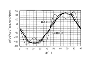
- FIG. 14 is a diagram comparing the cogging torque Tcog, harv of the first rotating body 2 with the cogging torque Tcog, gen of the second rotating body 4 finally obtained by the above-described method.
- Tcog, harv and Tcong, gen are almost opposite in phase, and as a result, the overall cogging torque could be reduced by about 90%.
- the magnetic flux caused by the eddy current generated on one side surface of the moving body 5 due to the movement or rotation of the moving body 5 and the first rotating body 2 arranged opposite to the one side surface of the moving body 5 are used.
- the 1st rotary body 2 can be rotated by the attractive force and repulsive force with the magnetic flux of 1 permanent magnet 2a.
- the second rotating body 4 that rotates integrally with the first rotating body 2 is provided, and the tips of the teeth 6 a of the stator 6 disposed on the inner peripheral side of the second rotating body 4 and the second rotating body 4.
- the cogging torque generated by the rotation of the first rotating body 2 is generated in the second rotating body 4 and the two rotating bodies 4 cancel each other.
- the cogging torque can be reduced to near zero.
- cogging torque generated in the first rotating body 2 is generated in the second rotating body 4 by using the second rotating body 4 and the stator 6 that rotate integrally with the first rotating body 2.
- the specific means for canceling the cogging torque is not limited to that described in the first embodiment.
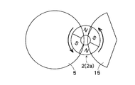
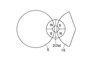
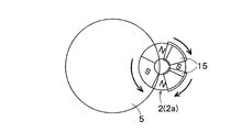
- FIG. 15A and FIG. 15B are diagrams for explaining the concept of the second embodiment.
- 15A and 15B show an example in which the yoke 15 is arranged point-symmetrically with the moving body 5 with respect to the first rotating body 2.
- the S pole is larger in area than the N pole, and counterclockwise cogging torque is generated.
- the S pole is larger in area than the N pole, so that counterclockwise cogging torque is also generated. Accordingly, the counterclockwise cogging torque is further increased as compared with the case without the yoke 15. In this case, the cogging torque of the first rotating body 2 cannot be canceled by the yoke 15.
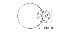
- FIG. 16A shows an example in which the yoke 15 is overlapped in almost all regions other than the region overlapping the moving body 5 of the first rotating body 2.
- the magnetic characteristic of the yoke 15 that is, the magnetic permeability is the same as the magnetic characteristic of the moving body 5 and the gap between the first rotating body 2 and the yoke 15 is equal to the gap between the moving body 5 and the first rotating body 2
- the cogging torque generated in the first rotating body 2 is reduced.
- the cogging torque itself is not generated in the first rotating body 2 rather than canceling out the cogging torque generated in the first rotating body 2 by the moving body 5.
- FIG. 16B shows an example of using a plurality of yokes 15 to optimize the location of each yoke 15 so as to cancel the cogging torque generated in the first rotating body 2 by the moving body 5.
- two yokes 15 are used, but it is desirable to optimize the magnetic characteristics such as the number, shape, and permeability of the yokes 15.
- simulation may be used as in the first embodiment.
- the yoke 15 in FIG. 16A and the yoke 15 in FIG. 16B constitute the cogging torque canceling unit 8.
- the yoke 15 in FIG. 16A reduces the cogging torque itself generated in the first rotating body 2 as described above, but is generated in the first rotating body 2 by the moving body 5 when the yoke 15 is not provided.
- the cogging torque is offset by providing the yoke 15, and as a result, the cogging torque itself generated in the first rotating body 2 is reduced. Therefore, the yoke 15 in FIG. 16A also functions as the cogging torque canceling unit 8.
- the cogging torque itself is not generated in the first rotating body 2 by arranging the yoke 15 so as to at least partially overlap the first permanent magnet 2 a of the first rotating body 2.
- the cogging torque generated in the first rotating body 2 by the moving body 5 can be canceled by the yoke 15.
- a second rotating body 4 separate from the first rotating body 2 is provided, and both the first rotating body 2 and the second rotating body 4 are disposed close to the moving body 5.
- FIG. 17 is a diagram for explaining the concept of the third embodiment.
- the cogging torque canceling unit 8 according to the third embodiment includes the second rotating body 4 and a synchronous rotating mechanism.
- the second rotating body 4 includes a second permanent magnet 4 a that is spaced from and arranged on one main surface of the moving body 5 and rotates around a predetermined rotation axis in accordance with the rotation or moving direction of the moving body 5.
- the synchronous rotating mechanism rotates the first rotating body 2 and the second rotating body 4 in synchronization.
- An example of the synchronous rotation mechanism is a timing belt 16 that spans the rotation axes of the first rotating body 2 and the second rotating body 4.
- the synchronous rotation mechanism is not necessarily limited to the timing belt 16 and may be a gear or the like.
- the second rotating body 4 is disposed so as to overlap the moving body 5, similarly to the first rotating body 2.
- the area where the first rotating body 2 and the moving body 5 overlap includes the N pole and the S pole in equal areas, whereas the second rotating body 4 and the moving body 5
- the overlapping region contains more S poles than N poles. That is, the second rotator 4 is arranged 45 ° apart from the first rotator 2. Thereby, the cogging torque generated in the first rotating body 2 by the moving body 5 can be canceled by the cogging torque generated in the second rotating body 4 by the moving body 5.
- the diameter size, the number of magnetic poles, the magnetic characteristics, and the gap between the moving body 5 and the first rotating body 2 and the second rotating body 4 are common.
- the moving body 5 may rotate.
- the first rotating body 2 and the second rotating body 4 are arranged so as to overlap the moving body 5, and the first rotating body 2 and the second rotating body 4 rotate integrally.
- the cogging torque generated in the first rotating body 2 by the moving body 5 is The cogging torque generated in the second rotating body 4 can be canceled out.
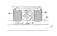
- FIG. 18A is a diagram illustrating a first example of the rotating electrical machine 10 to which the cogging torque canceling unit 8 can be attached.
- the non-contact generator 1 of FIG. 18A includes a first permanent magnet 2a that rotates around a rotation axis, two coils 7 (a first coil 7a and a second coil 7b), and a yoke 15.
- the first permanent magnet 2a is disposed on the main surface 5c of the moving body 5 that rotates or moves to be spaced apart from the first permanent magnet 2a, and rotates according to the rotation or moving direction of the moving body 5.
- the first permanent magnet 2a has at least two magnetic poles 2b, and the magnetization direction of each magnetic pole 2b is the normal direction of the outer peripheral surface of the first permanent magnet 2a.
- the outer peripheral surface 2c of the first permanent magnet 2a is spaced apart from the one main surface 5c of the moving body 5, and the first permanent magnet 2a rotates without contacting the one main surface 5c of the moving body 5. It is supposed to be free.
- one first coil 7 a of the two coils 7 is disposed on the rear side of the first permanent magnet 2 a with respect to the rotation or movement direction of the moving body 5.
- the other second coil 7 b is arranged on the front side of the first permanent magnet 2 a with respect to the rotation or movement direction of the moving body 5.
- the first and second coils 7 a and 7 b are arranged on the main surface 5 c of the moving body 5 so as to be separated from each other.
- a U-shaped yoke 15 is disposed inside and above the first and second coils 7a and 7b. There is a gap between the yoke 15 and the first permanent magnet 2a, and similarly there is a gap between the first permanent magnet 2a and the first and second coils 7a and 7b. These gaps are air gaps. Therefore, the first permanent magnet 2 a rotates within a region surrounded by one main surface of the moving body 5, the first and second coils 7 a and 7 b, and the yoke 15.
- the coil 7 in FIG. 18A may be disposed at a location where the total magnetic flux from the first permanent magnet 2a is concentrated, and the arrangement example of the coil 7 in FIG. 18A is merely an example. Further, the shape of the yoke 15 is not limited to that shown in FIG. 18A.
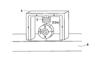
- FIG. 18B is a diagram illustrating a second example of the rotating electrical machine 10 to which the cogging torque canceling unit 8 can be attached, and is a diagram illustrating an example in which power is generated by one coil 7.
- a coil 7 wound around a yoke 15 is disposed above the first permanent magnet 2a.
- the yoke 15 extends from above the first permanent magnet 2a to both sides in the moving direction of the moving body 5, and is disposed so as to surround the first permanent magnet 2a. Since the coil 7 links almost all the magnetic flux from the first permanent magnet 2a, it is not always necessary to provide a plurality of coils 7.
- the location where the coil 7 is disposed may be a location where all the magnetic flux from the first permanent magnet 2a is concentrated (for example, in the vicinity of at least one of the north and south poles of the first permanent magnet 2a).
- the cogging torque canceling unit 8 described in the first to third embodiments is also provided. desirable.
- 1 non-contact generator 2 first rotating body, 2a first permanent magnet, 2b magnetic pole, 3 rotor, 4 second rotating body, 6 stator, 7 coil, 8 cogging torque canceling unit, 9a rotating shaft, 10 rotating electric machine, 11 Kinetic energy harvester, 12 generator, 13 drive controller
Landscapes
- Engineering & Computer Science (AREA)
- Power Engineering (AREA)
- Permanent Magnet Type Synchronous Machine (AREA)
- Connection Of Motors, Electrical Generators, Mechanical Devices, And The Like (AREA)
- Dynamo-Electric Clutches, Dynamo-Electric Brakes (AREA)
- Permanent Field Magnets Of Synchronous Machinery (AREA)
Abstract
L'invention concerne un moteur rotatif et un générateur sans contact doté d'une bonne efficacité magnétique, d'une faible fuite de flux magnétique et d'une compensation du couple de détente. Un moteur rotatif (10) comprend : un premier corps rotatif (2) qui présente des premiers aimants permanents (2a) disposés en regard et séparés l'un de l'autre sur une surface principale d'un corps mobile qui tourne ou se déplace, et qui tourne autour d'un axe de rotation prescrit en fonction de la direction de rotation ou de mouvement du corps mobile ; et une unité d'annulation de couple de détente (8) qui annule au moins une partie du couple de détente produit par les premiers aimants permanents en raison des formes relatives et de la relation de position entre le corps mobile et les premiers aimants permanents. Le premier corps rotatif (2) tourne autour d'un premier axe de rotation du fait de la force de répulsion et de la force d'attraction qui agit sur les premiers aimants permanents sur la base d'un courant de Foucault produit dans une direction qui empêche les changements du flux magnétique généré par les premiers aimants permanents sur la surface principale d'un corps mobile (5). Une surface latérale du premier corps rotatif disposée en regard du corps mobile présente une vitesse de surface inférieure à celle de la surface principale du corps mobile disposée en regard de la surface latérale.
Priority Applications (3)
| Application Number | Priority Date | Filing Date | Title |
|---|---|---|---|
| CN201780044511.5A CN109478838B (zh) | 2016-07-20 | 2017-07-19 | 旋转电机和非接触发电机 |
| JP2018528843A JP6685399B2 (ja) | 2016-07-20 | 2017-07-19 | 回転電機および非接触発電機 |
| EP17831061.1A EP3490121B1 (fr) | 2016-07-20 | 2017-07-19 | Moteur rotatif et générateur sans contact |
Applications Claiming Priority (2)
| Application Number | Priority Date | Filing Date | Title |
|---|---|---|---|
| JP2016142820 | 2016-07-20 | ||
| JP2016-142820 | 2016-07-20 |
Publications (1)
| Publication Number | Publication Date |
|---|---|
| WO2018016545A1 true WO2018016545A1 (fr) | 2018-01-25 |
Family
ID=60992570
Family Applications (1)
| Application Number | Title | Priority Date | Filing Date |
|---|---|---|---|
| PCT/JP2017/026167 Ceased WO2018016545A1 (fr) | 2016-07-20 | 2017-07-19 | Moteur rotatif et générateur sans contact |
Country Status (4)
| Country | Link |
|---|---|
| EP (1) | EP3490121B1 (fr) |
| JP (1) | JP6685399B2 (fr) |
| CN (1) | CN109478838B (fr) |
| WO (1) | WO2018016545A1 (fr) |
Cited By (1)
| Publication number | Priority date | Publication date | Assignee | Title |
|---|---|---|---|---|
| JP2024019784A (ja) * | 2022-08-01 | 2024-02-14 | 株式会社東京理工舎 | ローラコンベアシステム |
Citations (3)
| Publication number | Priority date | Publication date | Assignee | Title |
|---|---|---|---|---|
| JP2011254618A (ja) * | 2010-06-02 | 2011-12-15 | Fuji Electric Co Ltd | アキシャルギャップモータ |
| WO2012101938A1 (fr) * | 2011-01-26 | 2012-08-02 | 株式会社日立産機システム | Bloc-moteur, et machine dynamo-électrique et dispositif de machine dynamo-électrique utilisant ledit bloc-moteur |
| JP2014073076A (ja) * | 2012-09-27 | 2014-04-21 | Sunrising Eco-Friendly Technology Co Ltd | 磁気誘導式回転子部材、非接触式発電装置及び自転車用非接触式発光装置 |
Family Cites Families (3)
| Publication number | Priority date | Publication date | Assignee | Title |
|---|---|---|---|---|
| WO2013106919A1 (fr) * | 2012-01-20 | 2013-07-25 | Idénergie Inc. | Appareil électrique utilisant une production de courant de foucault pour transmettre un couple entre deux rotors adjacents |
| CN104734446A (zh) * | 2015-04-09 | 2015-06-24 | 莱克电气股份有限公司 | 一种内置式永磁同步电机 |
| CN105763009B (zh) * | 2016-04-20 | 2018-02-27 | 山东大学 | 混合磁路低谐波多定子弱磁扩速永磁同步电机及其方法 |
-
2017
- 2017-07-19 WO PCT/JP2017/026167 patent/WO2018016545A1/fr not_active Ceased
- 2017-07-19 JP JP2018528843A patent/JP6685399B2/ja active Active
- 2017-07-19 EP EP17831061.1A patent/EP3490121B1/fr active Active
- 2017-07-19 CN CN201780044511.5A patent/CN109478838B/zh active Active
Patent Citations (3)
| Publication number | Priority date | Publication date | Assignee | Title |
|---|---|---|---|---|
| JP2011254618A (ja) * | 2010-06-02 | 2011-12-15 | Fuji Electric Co Ltd | アキシャルギャップモータ |
| WO2012101938A1 (fr) * | 2011-01-26 | 2012-08-02 | 株式会社日立産機システム | Bloc-moteur, et machine dynamo-électrique et dispositif de machine dynamo-électrique utilisant ledit bloc-moteur |
| JP2014073076A (ja) * | 2012-09-27 | 2014-04-21 | Sunrising Eco-Friendly Technology Co Ltd | 磁気誘導式回転子部材、非接触式発電装置及び自転車用非接触式発光装置 |
Non-Patent Citations (1)
| Title |
|---|
| See also references of EP3490121A4 * |
Cited By (1)
| Publication number | Priority date | Publication date | Assignee | Title |
|---|---|---|---|---|
| JP2024019784A (ja) * | 2022-08-01 | 2024-02-14 | 株式会社東京理工舎 | ローラコンベアシステム |
Also Published As
| Publication number | Publication date |
|---|---|
| EP3490121A1 (fr) | 2019-05-29 |
| EP3490121A4 (fr) | 2020-02-19 |
| CN109478838A (zh) | 2019-03-15 |
| CN109478838B (zh) | 2021-04-09 |
| JP6685399B2 (ja) | 2020-04-22 |
| JPWO2018016545A1 (ja) | 2019-04-04 |
| EP3490121B1 (fr) | 2021-09-29 |
Similar Documents
| Publication | Publication Date | Title |
|---|---|---|
| JP6781489B2 (ja) | 電磁装置 | |
| JP6639810B2 (ja) | 回転電機および非接触発電機 | |
| JP5857627B2 (ja) | 電動回転機 | |
| JP2013094020A (ja) | 電動回転機 | |
| JP2013038944A (ja) | モータ | |
| US20100308674A1 (en) | Magnetic machine | |
| Sakaidani et al. | Experimental verification of feedback control of a 2-DOF spherical actuator | |
| WO2016199845A1 (fr) | Machine électrique tournante et générateur électrique sans contact | |
| JP2015104180A (ja) | 回転電機の回転子 | |
| JP2016536952A (ja) | ハイブリッド車のための改良されたスイッチトリラクタンスモータ及びスイッチトリラクタンス装置 | |
| MX2014015793A (es) | Nuevo dispositivo. | |
| JP2012244874A (ja) | 回転電機 | |
| JP2016025700A (ja) | 磁気ねじアクチュエータ | |
| JP6685399B2 (ja) | 回転電機および非接触発電機 | |
| Kang et al. | Method of current compensation for reducing error of holding torque of permanent-magnet spherical wheel motor | |
| JP2011182638A (ja) | 磁気変速機組立体 | |
| WO2015136758A1 (fr) | Moteur linéaire | |
| JP6332094B2 (ja) | ロータ、電動モータ | |
| CN110754038B (zh) | 电动机控制装置以及电动机系统 | |
| Li et al. | Halbach array magnet and its application to PM spherical motor | |
| Takahara et al. | Proposal of 3-degree-of-freedom spherical actuator with auxiliary poles | |
| JP5708566B2 (ja) | 電磁カップリング | |
| RU81395U1 (ru) | Магнитоэлектрический генератор | |
| Zhou et al. | Structural design and FEA of a new type of multi-DOF spherical induction motor without output shaft | |
| JP7665489B2 (ja) | 回転電機 |
Legal Events
| Date | Code | Title | Description |
|---|---|---|---|
| 121 | Ep: the epo has been informed by wipo that ep was designated in this application |
Ref document number: 17831061 Country of ref document: EP Kind code of ref document: A1 |
|
| ENP | Entry into the national phase |
Ref document number: 2018528843 Country of ref document: JP Kind code of ref document: A |
|
| NENP | Non-entry into the national phase |
Ref country code: DE |
|
| ENP | Entry into the national phase |
Ref document number: 2017831061 Country of ref document: EP Effective date: 20190220 |