WO2018016575A1 - 電解水生成装置 - Google Patents
電解水生成装置 Download PDFInfo
- Publication number
- WO2018016575A1 WO2018016575A1 PCT/JP2017/026256 JP2017026256W WO2018016575A1 WO 2018016575 A1 WO2018016575 A1 WO 2018016575A1 JP 2017026256 W JP2017026256 W JP 2017026256W WO 2018016575 A1 WO2018016575 A1 WO 2018016575A1
- Authority
- WO
- WIPO (PCT)
- Prior art keywords
- switching
- water
- flow path
- chamber
- electrolysis
- Prior art date
- Legal status (The legal status is an assumption and is not a legal conclusion. Google has not performed a legal analysis and makes no representation as to the accuracy of the status listed.)
- Ceased
Links
Images

Classifications
-
- C—CHEMISTRY; METALLURGY
- C02—TREATMENT OF WATER, WASTE WATER, SEWAGE, OR SLUDGE
- C02F—TREATMENT OF WATER, WASTE WATER, SEWAGE, OR SLUDGE
- C02F1/00—Treatment of water, waste water, or sewage
- C02F1/46—Treatment of water, waste water, or sewage by electrochemical methods
- C02F1/461—Treatment of water, waste water, or sewage by electrochemical methods by electrolysis
- C02F1/467—Treatment of water, waste water, or sewage by electrochemical methods by electrolysis by electrochemical disinfection; by electrooxydation or by electroreduction
- C02F1/4676—Treatment of water, waste water, or sewage by electrochemical methods by electrolysis by electrochemical disinfection; by electrooxydation or by electroreduction by electroreduction
-
- C—CHEMISTRY; METALLURGY
- C02—TREATMENT OF WATER, WASTE WATER, SEWAGE, OR SLUDGE
- C02F—TREATMENT OF WATER, WASTE WATER, SEWAGE, OR SLUDGE
- C02F1/00—Treatment of water, waste water, or sewage
- C02F1/46—Treatment of water, waste water, or sewage by electrochemical methods
- C02F1/461—Treatment of water, waste water, or sewage by electrochemical methods by electrolysis
- C02F1/46104—Devices therefor; Their operating or servicing
-
- C—CHEMISTRY; METALLURGY
- C02—TREATMENT OF WATER, WASTE WATER, SEWAGE, OR SLUDGE
- C02F—TREATMENT OF WATER, WASTE WATER, SEWAGE, OR SLUDGE
- C02F1/00—Treatment of water, waste water, or sewage
- C02F1/46—Treatment of water, waste water, or sewage by electrochemical methods
-
- C—CHEMISTRY; METALLURGY
- C02—TREATMENT OF WATER, WASTE WATER, SEWAGE, OR SLUDGE
- C02F—TREATMENT OF WATER, WASTE WATER, SEWAGE, OR SLUDGE
- C02F1/00—Treatment of water, waste water, or sewage
- C02F1/46—Treatment of water, waste water, or sewage by electrochemical methods
- C02F1/461—Treatment of water, waste water, or sewage by electrochemical methods by electrolysis
- C02F1/46104—Devices therefor; Their operating or servicing
- C02F1/4618—Devices therefor; Their operating or servicing for producing "ionised" acidic or basic water
-
- C—CHEMISTRY; METALLURGY
- C02—TREATMENT OF WATER, WASTE WATER, SEWAGE, OR SLUDGE
- C02F—TREATMENT OF WATER, WASTE WATER, SEWAGE, OR SLUDGE
- C02F1/00—Treatment of water, waste water, or sewage
- C02F1/46—Treatment of water, waste water, or sewage by electrochemical methods
- C02F1/461—Treatment of water, waste water, or sewage by electrochemical methods by electrolysis
- C02F1/46104—Devices therefor; Their operating or servicing
- C02F1/46109—Electrodes
- C02F2001/46119—Cleaning the electrodes
-
- C—CHEMISTRY; METALLURGY
- C02—TREATMENT OF WATER, WASTE WATER, SEWAGE, OR SLUDGE
- C02F—TREATMENT OF WATER, WASTE WATER, SEWAGE, OR SLUDGE
- C02F2201/00—Apparatus for treatment of water, waste water or sewage
- C02F2201/46—Apparatus for electrochemical processes
- C02F2201/461—Electrolysis apparatus
- C02F2201/46105—Details relating to the electrolytic devices
- C02F2201/46115—Electrolytic cell with membranes or diaphragms
-
- C—CHEMISTRY; METALLURGY
- C02—TREATMENT OF WATER, WASTE WATER, SEWAGE, OR SLUDGE
- C02F—TREATMENT OF WATER, WASTE WATER, SEWAGE, OR SLUDGE
- C02F2201/00—Apparatus for treatment of water, waste water or sewage
- C02F2201/46—Apparatus for electrochemical processes
- C02F2201/461—Electrolysis apparatus
- C02F2201/46105—Details relating to the electrolytic devices
- C02F2201/4612—Controlling or monitoring
- C02F2201/46125—Electrical variables
- C02F2201/4613—Inversing polarity
-
- C—CHEMISTRY; METALLURGY
- C02—TREATMENT OF WATER, WASTE WATER, SEWAGE, OR SLUDGE
- C02F—TREATMENT OF WATER, WASTE WATER, SEWAGE, OR SLUDGE
- C02F2201/00—Apparatus for treatment of water, waste water or sewage
- C02F2201/46—Apparatus for electrochemical processes
- C02F2201/461—Electrolysis apparatus
- C02F2201/46105—Details relating to the electrolytic devices
- C02F2201/4612—Controlling or monitoring
- C02F2201/46125—Electrical variables
- C02F2201/46135—Voltage
-
- C—CHEMISTRY; METALLURGY
- C02—TREATMENT OF WATER, WASTE WATER, SEWAGE, OR SLUDGE
- C02F—TREATMENT OF WATER, WASTE WATER, SEWAGE, OR SLUDGE
- C02F2201/00—Apparatus for treatment of water, waste water or sewage
- C02F2201/46—Apparatus for electrochemical processes
- C02F2201/461—Electrolysis apparatus
- C02F2201/46105—Details relating to the electrolytic devices
- C02F2201/4612—Controlling or monitoring
- C02F2201/46125—Electrical variables
- C02F2201/4614—Current
-
- C—CHEMISTRY; METALLURGY
- C02—TREATMENT OF WATER, WASTE WATER, SEWAGE, OR SLUDGE
- C02F—TREATMENT OF WATER, WASTE WATER, SEWAGE, OR SLUDGE
- C02F2201/00—Apparatus for treatment of water, waste water or sewage
- C02F2201/46—Apparatus for electrochemical processes
- C02F2201/461—Electrolysis apparatus
- C02F2201/46105—Details relating to the electrolytic devices
- C02F2201/4612—Controlling or monitoring
- C02F2201/46145—Fluid flow
-
- Y—GENERAL TAGGING OF NEW TECHNOLOGICAL DEVELOPMENTS; GENERAL TAGGING OF CROSS-SECTIONAL TECHNOLOGIES SPANNING OVER SEVERAL SECTIONS OF THE IPC; TECHNICAL SUBJECTS COVERED BY FORMER USPC CROSS-REFERENCE ART COLLECTIONS [XRACs] AND DIGESTS
- Y02—TECHNOLOGIES OR APPLICATIONS FOR MITIGATION OR ADAPTATION AGAINST CLIMATE CHANGE
- Y02E—REDUCTION OF GREENHOUSE GAS [GHG] EMISSIONS, RELATED TO ENERGY GENERATION, TRANSMISSION OR DISTRIBUTION
- Y02E60/00—Enabling technologies; Technologies with a potential or indirect contribution to GHG emissions mitigation
- Y02E60/30—Hydrogen technology
- Y02E60/36—Hydrogen production from non-carbon containing sources, e.g. by water electrolysis
Definitions
- the present invention relates to an electrolyzed water generating apparatus for electrolyzing water to generate electrolyzed hydrogen water.
- an electrolyzed water generating apparatus that includes an electrolytic cell having an anode chamber and a cathode chamber partitioned by a diaphragm and electrolyzes raw water such as tap water supplied to the electrolyzer is known (for example, Patent Document 1). reference).
- electrolyzed hydrogen water electrolyzed hydrogen water (electrolytically reduced water) in which hydrogen gas is dissolved is generated.
- the water remaining inside the electrolytic cell may be discharged without being sufficiently electrolyzed, so that a predetermined time (for example, several seconds from the start of water discharge) It is desirable not to use water until) has passed.
- the raw water electrolyzed by the electrolytic cell contains a small amount of metal ions such as calcium ions and magnesium ions. These metal ions are not easily removed by a filter or the like, and when entering the electrolytic cell, they are deposited as scales in the cathode chamber including the power feeding body and in the flow path connected to the downstream side of the cathode chamber.
- an electrolyzed water generating device configured to suppress adhesion of scale to the power feeding body by appropriately switching the polarity of the power feeding body arranged inside the electrolytic cell after the electrolysis is stopped. Yes.
- this type of electrolyzed water generating device when switching the polarity of the power feeding body, by operating the flow path switching valve to switch the upstream and downstream water channels synchronously, the same kind as before switching from the water outlet Usability is improved by allowing electrolyzed water to be discharged.
- electrolyzed water generated in a different polarity remains in the electrolytic cell and the flow path replacement valve immediately after switching the polarity of the power feeding body. For this reason, in order to prevent mixing with the electrolyzed water generated at a different polarity and to obtain the desired electrolyzed water, it is necessary to wait for the water to be discharged from the water outlet and take water accordingly. Waiting time occurs. The waiting time until the electrolyzed water generated with a different polarity is discharged when the polarity of the power feeder is switched is longer than the waiting time when the polarity is not switched, and the usability of the electrolyzed water generator is improved. For this purpose, further improvements are desired. Moreover, the water produced in a different polarity is usually discarded as discarded water, which is one factor that hinders the effective use of water.
- the present invention has been devised in view of the actual situation as described above, and provides an electrolyzed water generating apparatus capable of improving usability and reducing waste water while suppressing the adhesion of scales to a power feeding body. This is the main purpose.
- the present invention includes an electrolysis chamber to which water to be electrolyzed is supplied, a first power feeding body and a second power feeding body that are arranged to face each other in the electrolysis chamber, the first power feeding body, and the second power feeding.
- An electrolyzed water generating device comprising a diaphragm disposed between a body and dividing the electrolysis chamber into a first electrode chamber on the first power feeder side and a second electrode chamber on the second power feeder side A first flow path for sending electrolyzed water generated in one of the first electrode chamber or the second electrode chamber to a first water outlet, and the other of the first electrode chamber or the second electrode chamber.
- Flow path switching for switching the connection between the second flow path for sending the generated electrolyzed water to the second water discharge port, the first polar chamber and the second polar chamber, and the first flow path and the second flow path Valve, polarity switching means for switching the polarity of the first power supply body and the second power supply body, and the timing for switching the polarity switching means and the flow path switching valve.
- a water flow detecting means for detecting water flow to the electrolysis chamber, wherein the determination means performs electrolysis more than a predetermined number of times in the electrolysis chamber without switching the polarity. After being performed, it is determined that the switching time has arrived when a predetermined time has elapsed without detecting water flow into the electrolysis chamber.
- the determination unit integrates the electrolysis time in the electrolysis chamber, and after the electrolysis is performed more than the number of times in the electrolysis chamber without switching the polarity. It is desirable to determine that the switching time has arrived when the time has elapsed and the accumulated electrolysis time has reached a predetermined threshold value.
- the electrolyzed water generating device further includes a current detecting unit that detects a current supplied to the first power feeding body and the second power feeding body, and the determination unit switches the polarity and the flow path. It is desirable to change the number of times based on the integrated value of the current after.
- the determination unit changes the time based on the polarity and the integrated value of the current after switching the flow path.
- the electrolyzed water generating device further includes voltage detection means for detecting a voltage applied to the first power supply body and the second power supply body, and the determination means switches the polarity and the flow path. It is desirable to change the number of times based on a ratio between the voltage and the current after the operation.
- the determination unit changes the time based on the ratio between the voltage and the current.
- the determination means is that the switching time has arrived on the premise that electrolysis has been performed more than a predetermined number of times in the electrolysis chamber without switching the polarity of each power feeder. judge.
- the determination means determines that the switching time has arrived when a predetermined time has elapsed without detecting water flow into the electrolysis chamber after electrolysis has been performed more than the above number of times. Therefore, for example, during cooking, when water is passed through the electrolysis chamber a plurality of times in a short time, the polarity switching is not executed. Therefore, the occurrence frequency of the situation where the waiting time becomes longer as the polarity is switched is reduced, and the usability of the electrolyzed water generating device is further enhanced.
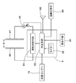
- FIG. 1 It is a block diagram which shows the flow-path structure of one Embodiment of the electrolyzed water generating apparatus of this invention. It is a flowchart which shows the electrical structure of the electrolyzed water generating apparatus of FIG. It is a flowchart which shows the process sequence of the switching operation
- FIG. 1 shows a schematic configuration of an electrolyzed water generating apparatus 1 of the present embodiment.
- the electrolyzed water generating device for example, a home electrolyzed water generating device used for generating home drinking water is shown.
- FIG. 1 shows an electrolyzed water generating apparatus 1 in a state where potable electrolyzed hydrogen water is generated.
- the electrolyzed water generating apparatus 1 includes a water purification cartridge 2 for purifying water and an electrolyzer 4 in which an electrolysis chamber 40 to which purified water is supplied is formed.
- the purified water cartridge 2 generates purified water by filtering the raw water supplied to the electrolyzed water generating device 1 and supplies the purified water to the electrolysis chamber 40.
- the raw water tap water is generally used, but well water, ground water, and the like can be used.
- the water purification cartridge 2 is configured to be detachable from the apparatus main body of the electrolyzed water generating apparatus 1. Thereby, the water purification cartridge 2 that has reached the end of its life due to use or over time can be replaced with a new water purification cartridge 2.
- the water purification cartridge 2 is provided upstream of the electrolytic cell 4. Therefore, the water purified by the water purification cartridge 2 is supplied to the electrolytic cell 4.
- the water purified by the water purification cartridge 2 is electrolyzed in the electrolysis chamber 40.
- the electrolysis chamber 40 is provided with a first power feeding body 41 and a second power feeding body 42 that are arranged to face each other, and a diaphragm 43 that is disposed between the first power feeding body 41 and the second power feeding body 42. ing.
- the diaphragm 43 divides the electrolysis chamber 40 into a first electrode chamber 40a on the first power supply body 41 side and a second electrode chamber 40b on the second power supply body 42 side.
- the diaphragm 43 allows ions generated by electrolysis to pass therethrough, and the first power feeder 41 and the second power feeder 42 are electrically connected via the diaphragm 43.
- a DC voltage is applied between the first power supply body 41 and the second power supply body 42, water is electrolyzed in the electrolysis chamber 40, and electrolyzed water is obtained.
- the first power supply body 41 is charged with a positive charge, and the first electrode chamber 40a functions as an anode chamber.
- negative charge is charged in the second power feeding body 42, and the second electrode chamber 40b functions as a cathode chamber. That is, reducing electrolyzed hydrogen water in which the generated hydrogen gas is dissolved is generated in the second electrode chamber 40b, and electrolytic acid water in which the generated oxygen gas is dissolved in the first electrode chamber 40a.
- FIG. 2 shows the electrical configuration of the electrolyzed water generator 1.
- the electrolyzed water generating apparatus 1 includes a control unit 5 that controls each part of the electrolyzer 4 and the like.
- the first power supply 41 and the second power supply 42 and the control means 5 are connected via a current supply line.
- Current detection means 44 is provided on the current supply line between the first power feeder 41 and the control means 5.
- the current detection unit 44 may be provided in a current supply line between the second power feeder 42 and the control unit 5.
- the current detection means 44 detects a direct current (electrolytic current) I supplied to the first power supply body 41 and the second power supply body 42 at all times or periodically, and outputs an electric signal corresponding to the value to the control means 5. .
- the control means 5 controls the DC voltage (electrolytic voltage) V applied to the first power supply body 41 and the second power supply body 42 based on, for example, the electrical signal output from the current detection means 44. More specifically, the controller 5 controls the first power feeder 41 and the first feeder 41 so that the current I detected by the current detector 44 becomes a desired value according to the dissolved hydrogen concentration set by the user or the like. 2.
- the voltage V applied to the power feeder 42 is feedback controlled. For example, when the current I is excessive, the control unit 5 decreases the voltage V, and when the current I is excessive, the control unit 5 increases the voltage V. Accordingly, the current I supplied to the first power supply body 41 and the second power supply body 42 is appropriately controlled, and hydrogen water having a desired dissolved hydrogen concentration is generated in the electrolysis chamber 40.
- the polarities of the first power supply body 41 and the second power supply body 42 are controlled by the control means 5. That is, the control unit 5 functions as a polarity switching unit 51 that switches the polarities of the first power feeding body 41 and the second power feeding body 42.
- the control means 5 By appropriately switching the polarities of the first power supply body 41 and the second power supply body 42 by the control means 5, the opportunity for the first power supply body 41 and the second power supply body 42 to function as an anode or a cathode is equalized.
- the power feeder functioning as the cathode before switching the polarity functions as the anode after switching the polarity, and cleans the scale deposited before the switching. Thereby, adhesion of the scale to the 1st electric power feeder 41, the 2nd electric power feeder 42, etc. is suppressed.
- the control means 5 includes, for example, a CPU (Central Processing Unit) that executes various arithmetic processes, information processing, etc., a program that controls the operation of the CPU, and a memory that stores various information.
- a CPU Central Processing Unit
- Various functions of the control means 5 are realized by a CPU, a memory, and a program.
- the electrolyzed water generator 1 operates in various operation modes under the control of the control means 5.
- the operation mode of the electrolyzed water generating apparatus 1 includes “hydrogen water mode” for generating and discharging electrolytic hydrogen water, “acid water mode” for generating and discharging electrolytic acidic water, and “purified water for generating and discharging purified water” Mode "is included.
- the electrolyzed water generating apparatus 1 has operation means 61 operated by a user.
- the operation means 61 is operated by the user when changing the operation mode of the electrolyzed water generating device 1, for example.
- the operation means 61 includes a switch corresponding to each mode or a touch panel for detecting capacitance. Further, the user can select the water generated by the electrolyzed water generating apparatus 1 by operating the operating means 61. The user can set the dissolved hydrogen concentration of the electrolytic hydrogen water generated by the electrolyzed water generating apparatus 1 by operating the operating means 61. When the operation means 61 is operated by the user, the operation means 61 outputs a corresponding electric signal to the control means 5.
- the electrolyzed water generating apparatus 1 further includes a water inlet 7 provided on the upstream side of the electrolyzer 4 and a water outlet 8 provided on the downstream side of the electrolyzer 4.
- the water inlet 7 has a water supply pipe 71, a flow rate sensor 72, a branching portion 73, a flow rate adjustment valve 74, and the like.
- the water supply pipe 71 supplies the water purified by the water purification cartridge 2 to the electrolysis chamber 40.
- the flow rate sensor 72 is provided in the water supply pipe 71.
- the flow rate sensor 72 periodically detects the flow rate per unit time of water supplied to the electrolysis chamber 40 (hereinafter sometimes simply referred to as “flow rate”) F1, and outputs a signal corresponding to the value F1. Output to.
- the branch part 73 branches the water supply pipe 71 into two directions of the water supply pipes 71a and 71b.
- the flow rate adjustment valve 74 connects the water supply pipes 71a and 71b to the first electrode chamber 40a or the second electrode chamber 40b.
- the flow rate of water supplied to the first electrode chamber 40 a and the second electrode chamber 40 b is adjusted by the flow rate adjusting valve 74 under the control of the control means 5.
- the flow sensor 72 is provided on the upstream side of the branching portion 73, the flow rate of water supplied to the first electrode chamber 40a and the flow rate of water supplied to the second electrode chamber 40b are The sum, that is, the first flow rate F1 of water supplied to the electrolysis chamber 40 is detected.
- the water outlet 8 has a flow path switching valve 85, a first flow path 81, a second flow path 82, and the like.
- the flow path switching valve 85 switches the connection between the first polar chamber 40 a and the second polar chamber 40 b and the first flow path 81 and the second flow path 82.
- a first water outlet 83 is provided at the tip of the first flow path 81.
- the first flow path 81 delivers the electrolyzed water generated in one of the first electrode chamber 40 a or the second electrode chamber 40 b to the first water discharge port 83.
- a second water discharge port 84 is provided at the tip of the second flow path 82.
- the second flow path 82 sends the electrolyzed water generated in the other of the first electrode chamber 40 a or the second electrode chamber 40 b to the second water discharge port 84.
- the electrolyzed water selected by the user is always present.
- the water can be discharged from one water outlet (for example, the first water outlet 83).
- the control means 5 operate the flow rate adjustment valve 74 and the flow path switching valve 85 in conjunction with each other.
- water to the polar chamber connected to the second water discharge port 84 is secured while ensuring a sufficient amount of water supplied to the polar chamber connected to the first water discharge port 83. It is possible to suppress the supply amount and to effectively use water.
- the flow rate adjusting valve 74 and the flow path switching valve 85 are preferably formed integrally and driven in conjunction with a single motor.
- the flow rate adjustment valve 74 and the flow path switching valve 85 are configured by a cylindrical outer cylinder and an inner cylinder.
- the flow path which comprises the flow volume adjustment valve 74 and the flow-path switching valve 85 is formed in the inner side and the outer side of an inner cylinder, and each flow path is according to the operation state of the flow volume adjustment valve 74 and the flow path switching valve 85. It is configured to cross appropriately.
- Such a valve device is referred to as a “double auto change cross line valve”, contributes to the simplification of the configuration and control of the electrolyzed water generating device 1, and further increases the commercial value of the electrolyzed water generating device 1.
- the first power feeding body 41 and the second power feeding body in order to suppress the scale from adhering to the surfaces of the first power feeding body 41 and the second power feeding body 42, the first power feeding body 41 and the second power feeding body.
- the polarity of the body 42 is configured to be switched as appropriate.
- the switching timing of the polarities of the first power feeding body 41 and the second power feeding body 42 is managed by the control means 5.
- the control means 5 controls the flow path switching valve 85 so that the first electrode chamber 40a, the second electrode chamber 40b, and the second The connection between the first flow path 81 and the second flow path 82 is switched. That is, the control unit 5 functions as a determination unit 52 that determines the polarity of the first power supply body 41 and the second power supply body 42 and the switching timing of the flow path switching valve 85.
- the electrolyzed water generating apparatus 1 includes a speaker 62 for outputting various sounds for guiding user operations.
- the speaker 62 is controlled by the control means 5.
- the electrolyzed water discharged from the first water outlet 83 etc. immediately after the start of water flow is difficult to obtain a desired pH and dissolved gas concentration. For this reason, in this electrolyzed water generating apparatus 1, the pH of the electrolyzed water discharged from the first water outlet 83 and the dissolved gas concentration are stabilized, and after the elapse of T1 seconds, it is estimated that the desired electrolyzed water has been obtained.
- 62 is configured to sound a melody.
- T1 is set to, for example, about several seconds according to the specifications of the electrolysis chamber 40, the length of the first flow path 81, and the like.
- the first electrode chamber 40a, the second electrode chamber 40b, and the flow path switching valve 85 immediately after switching the polarity of the first power supply body 41 and the second power supply body 42 and the flow path switching valve 85 are generated with different polarities.
- the electrolyzed water remains. For this reason, the electrolyzed water generated immediately after switching the polarity of the second power feeding body 42 and the flow path switching valve 85 is mixed with the electrolyzed water generated with a different polarity. Therefore, in the present electrolyzed water generating apparatus 1, a melody is played from the speaker 62 after T2 (greater than T1) seconds estimated that the electrolyzed water generated in the different polarity is discharged from the first water outlet 83. It is configured.
- T2 is set to, for example, about twice T1 according to the specification of the flow path switching valve 85, the length of the first flow path 81, and the like.
- Times such as T1 seconds and T2 seconds are counted by the control means 5. That is, the control means 5 has a function as a timer 53 that counts time based on a clock signal or the like.
- a time such as T1 seconds or T2 seconds is set as a waiting time until the desired electrolyzed water is discharged after the start of water flow.
- the user can know that the selected electrolyzed water is generated by operating the operating means 61 by the melody that is played after the elapse of T1 seconds and after the elapse of T2, and the usability of the electrolyzed water generating apparatus 1 is improved. .
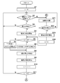
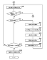
- FIGS. 3 and 4 are flowcharts showing the polarity of the first power supply body 41 and the second power supply body 42 and the switching operation of the flow path switching valve 85 in the electrolyzed water generating apparatus 1.
- a variable n corresponding to the number of times of electrolysis after switching the polarity is used to determine the polarity of each of the power feeding bodies 41 and 42 and the switching timing of the flow path switching valve 85.
- the control means 5 resets the variable n to 0 which is an initial value. Thereafter, when the operation mode is not switched by the user (Y in S2) and water flow is detected through the flow sensor 72 (Y in S3), the control means 5 performs the first power supply 41 and the second power supply. The DC voltage V is applied to the body 42 to start electrolysis (S4).
- the detection of water flow and water flow stop is determined based on a signal input from the flow sensor 72 to the control means 5. That is, the flow rate sensor 72 and the control unit 5 function as a water flow detection unit, and the control unit 5 determines that the water flow state is present when the flow rate at the flow rate sensor 72 exceeds a predetermined threshold value. When the flow rate at the flow rate sensor 72 is less than the threshold value, it is determined that the water flow is stopped.
- the control means 5 determines that the electrolysis is immediately after the polarity of the first power supply body 41 and the second power supply body 42 and the flow path switching valve 85 are switched. Then, after elapse of T2 seconds, a melody is output from the speaker 62 (S6). On the other hand, when the variable n is not 0 (N in S5), the control means 5 outputs a melody from the speaker 62 after the elapse of T1 seconds (S7).
- the control means 5 performs electrolysis by stopping the application of the DC voltage V to the first power supply body 41 and the second power supply body 42. Is stopped (S9), and the variable n is incremented by 1 (S10). In subsequent S11, it is determined whether or not the variable n reaches a predetermined number N (N is an integer of 2 or more). When the variable n does not reach the number N (N in S11), the process returns to S2 and the loop up to S11 is repeated. In this case, polarity switching is not performed.
- the control means 5 counts the time after the electrolysis is stopped (S12).
- the control means 5 The polarity of 41 and 42 and the switching time of the flow path switching valve 85 are judged to have arrived, and the polarity of each power supply body 41 and 42 and the flow path switching valve 85 are switched (S16).
- the processing of S1 to S16 is executed while constantly looping when the electrolyzed water generating apparatus 1 is operated. That is, after the process of S16 is completed, the process of S1 is executed. That is, in S16, the control means 5 switches the polarity of each electric power feeding body 41 and 42 and the flow-path switching valve 85, and prepares for the water flow detection (S3) by the flow sensor 72 of the next loop. As a result, the power feeder functioning as the cathode and generating electrolytic hydrogen water in the previous loop functions as the anode and cleans the deposited scale. Therefore, by repeating such a loop, the electrolytic hydrogen water generation step and the scale cleaning step are alternately repeated, and the scale may adhere to the surfaces of the first power supply body 41 and the second power supply body 42. , Continuously suppressed.
- the control means 5 applies a DC voltage V to the first power supply 41 and the second power supply 42 to perform electrolysis. Is started (S31), and after a lapse of T1 seconds, a melody is output from the speaker 62 (S32). Thereafter, when the water flow stop is detected via the flow sensor 72 (S33), the control means 5 performs electrolysis by stopping the application of the DC voltage V to the first power supply body 41 and the second power supply body 42. Is stopped (S34), the counted time is reset (S35), and the process returns to S12. In this case, polarity switching is not performed.
- the control means 5 does not switch the polarity of each of the power feeders 41 and 42 and is more than the predetermined number N in the electrolysis chamber 40.
- the switching time is determined on the assumption that electrolysis has been performed.
- the control means 5 does not detect the water flow into the electrolysis chamber after the electrolysis is performed N times or more.
- a predetermined time ⁇ T it is determined that the switching time has come. Therefore, for example, when the water is passed through the electrolysis chamber 40 a plurality of times in a short time during cooking (Y in S14), the polarity is not switched during that time. Accordingly, the waiting time until the desired electrolyzed water is discharged is maintained at T1 seconds without shifting to the processing from S1 to S6 in the next loop (S32). Therefore, the occurrence frequency of the situation where the waiting time becomes longer from T1 seconds to T2 seconds as the polarity is switched is reduced, and the usability of the electrolyzed water generating apparatus 1 is further enhanced.
- the flow path switching valve 85 is driven by, for example, a motor. Such switching of the flow path switching valve 85 is accompanied by an operation sound of the motor.
- the flow path switching valve is set at a time when it can be estimated that the user has moved to a location away from the electrolyzed water generating device 1 by appropriately determining the time ⁇ T (for example, about several minutes to several tens of minutes). 85 can be configured to be switched. Thereby, it is suppressed that a user is bothered by the operation sound of a motor.
- the control means 5 determines the switching timing based on the accumulated time of electrolysis. It may be configured to determine. In this case, the control means 5 integrates the electrolysis time in the electrolysis chamber 40. The control means 5 determines that the switching time has arrived when the accumulated electrolysis time has reached a predetermined threshold without switching the polarities of the first power feeding body 41 and the second power feeding body 42. If the operation mode is changed and the polarity is switched before the control means 5 determines that the switching time has arrived, the integrated value of the electrolysis time is reset to zero.
- the polarity switching timing is determined in consideration of the integration time of electrolysis, it is possible to reduce the frequency of switching the polarity with higher accuracy while suppressing the adhesion of the scale. As well as improving the usability, it becomes possible to reduce waste water.
- the determination of the switching time based on the accumulated time of electrolysis may be configured to function in accordance with the OR condition and the determination based on the number of times of electrolysis after polarity switching and the time after the electrolysis is stopped. In this case, scale adhesion can be more effectively suppressed.
- the current I supplied to the first power supply body 41 and the second power supply body 42 depends on the flow rate per unit time detected by the flow rate sensor 72.
- the current I depends on the dissolved hydrogen concentration set by the user. That is, as the flow rate of water supplied to the electrolytic cell 4 per unit time increases, the control means 5 is applied to the first power supply body 41 and the second power supply body 42 so that the current I increases.
- the voltage V is controlled. Further, as the dissolved hydrogen concentration is set higher, the control means 5 controls the voltage V applied to the first power supply body 41 and the second power supply body 42 so that the current I increases.
- the amount of scale deposition is proportional to the current I and the time during which electrolysis is performed.
- the control means 5 integrates the current I supplied to each of the power feeders 41 and 42 after switching the polarity of the power feeders 41 and 42 and the flow path switching valve 85 (the current I of the current I).
- the number N of times and the time ⁇ T may be changed based on the time integration value, and the integrated value of the current I is based on the electric signal output from the current detection means 44 and is controlled by the control means. 5 calculates.
- the amount of deposition of the scale is compared with the number of times of electrolysis. Can be estimated. For this reason, it is possible to increase the usability of the electrolyzed water generating device 1 by reducing the frequency of switching the polarity by setting the number of times N to be a threshold value large or setting the time ⁇ T large.
- the integrated value of the current I after switching the polarity of each of the power feeding bodies 41 and 42 and the flow path switching valve 85 is larger than a predetermined threshold value, the deposition amount of the scale is relatively large with respect to the number of times of electrolysis.
- the amount of scale deposition depends on the water component supplied to the electrolysis chamber 40. For example, when water containing a large amount of mineral components such as calcium is supplied to the electrolysis chamber 40, the amount of scale deposition tends to increase. Since the water containing a large amount of the mineral component has a small resistance value, a current I corresponding to the flow rate and the desired dissolved hydrogen water concentration can be obtained at a relatively low voltage V.
- the control means 5 uses the polarity of each of the power feeding bodies 41 and 42 and the voltage V applied to each of the power feeding bodies 41 and 42 after switching the flow path switching valve 85 and the supplied current I. Based on the ratio V / I, the number N of times and the time ⁇ T serving as threshold values may be changed. In this case, the control means 5 functions as a voltage detection means for detecting the voltage V to be feedback controlled constantly or periodically. The ratio V / I is calculated by the control means 5 based on the electrical signal and voltage V output from the current detection means 44. For example, the control unit 5 calculates the ratio V / I by periodically detecting the voltage V applied to each of the power feeding bodies 41 and 42 and the supplied current I, and further calculates the average value thereof. Thereby, the control means 5 can adjust the polarity and the switching frequency of the flow path switching valve 85 automatically according to the water quality of the area where the electrolyzed water generating apparatus 1 is used.
- the average value of the ratio V / I after switching the polarity of each of the power feeding bodies 41 and 42 and the flow path switching valve 85 is smaller than a predetermined threshold value, It can be estimated that the amount of precipitation is relatively large. For this reason, by setting the number of times N serving as the threshold value small or setting the time ⁇ T small, it is possible to increase the frequency of switching the polarity and suppress the adhesion of the scale.
- the average value of the ratio V / I after switching the polarity of each of the power feeding bodies 41 and 42 and the flow path switching valve 85 is larger than a predetermined threshold value, the deposition amount of the scale is compared with the number of times of electrolysis. Can be estimated. For this reason, it is possible to increase the usability of the electrolyzed water generating device 1 by reducing the frequency of switching the polarity by setting the number of times N to be a threshold value large or setting the time ⁇ T large.
- the electrolyzed water generating apparatus 1 includes at least an electrolysis chamber 40 to which water to be electrolyzed is supplied, and a first power feeding body 41 and a second power feeding body 42 that are disposed to face each other in the electrolysis chamber 40.
- the electrolysis chamber 40 is disposed between the first power supply body 41 and the second power supply body 42, and the electrolysis chamber 40 includes a first electrode chamber 40a on the first power supply body 41 side and a second electrode chamber 40b on the second power supply body 42 side.
- the flow path switching valve 85 for switching the connection with the path 82, and the polarity for switching the polarities of the first power supply body 41 and the second power supply body 42
- Control means 40 Electrolytic chamber 40a 1st electrode chamber 40b 2nd electrode chamber 41 1st electric power feeder 42 2nd electric power feeder 43 Diaphragm 44 Current detection means 51 Polarity switching means 52 Determination means 72 Flow rate sensor (water flow) Detection means) 81 1st flow path 82 2nd flow path 83 1st water discharge port 84 2nd water discharge port 85 Flow path switching valve
Landscapes
- Chemical & Material Sciences (AREA)
- Chemical Kinetics & Catalysis (AREA)
- Electrochemistry (AREA)
- General Chemical & Material Sciences (AREA)
- Life Sciences & Earth Sciences (AREA)
- Hydrology & Water Resources (AREA)
- Engineering & Computer Science (AREA)
- Environmental & Geological Engineering (AREA)
- Water Supply & Treatment (AREA)
- Organic Chemistry (AREA)
- Water Treatment By Electricity Or Magnetism (AREA)
Abstract
電解水生成装置は、電解室の第1極室又は第2極室の一方で生成された電解水を送出する第1流路と、他方で生成された電解水を送出する第2流路と、流量調整弁74及び流路切替弁85が連動するダブルオートチェンジクロスライン弁と、第1給電体41及び第2給電体42の極性を切り替える極性切替手段51と、極性切替手段51及び流路切替弁85の切替時期を判定する判定手段52とを備える。判定手段52は、極性が切り替えられることなく、電解室で予め定められた回数以上電気分解が行われた後、電解室への通水を検出することなく、予め定められた時間が経過したときに、切替時期が到来したと判定する。
Description
本発明は、水を電気分解して電解水素水を生成する電解水生成装置に関する。
従来、隔膜で仕切られた陽極室と陰極室とを有する電解槽を備え、電解槽に供給される水道水等の原水を電気分解する電解水生成装置が知られている(例えば、特許文献1参照)。電解水生成装置の陰極室では、水素ガスが溶け込んだ電解水素水(電解還元水)が生成される。上記電解水生成装置では、吐水を開始した直後、電解槽の内部に残留している水が十分に電気分解されることなく吐水されることがあるため、吐水開始から所定時間(例えば、数秒間)が経過するまでの水は使用しないことが望ましい。
一方、電解槽によって電気分解される原水には、微量ながらカルシウムイオンやマグネシウムイオン等の金属イオンが含まれている。これらの金属イオンは、フィルター等では除去されにくく、電解槽に進入すると給電体を含む陰極室の内部や陰極室の下流側に接続された流路の内部にスケールとして析出される。
スケールが給電体の表面に付着すると、水が電気分解され難くなり、電解水素水の溶存水素濃度が低下する。そこで、電気分解の停止後、電解槽の内部に配されている給電体の極性を適宜切り替えることにより、給電体へのスケールの付着を抑制するように構成された電解水生成装置が提案されている。この種の電解水生成装置では、給電体の極性を切り替える際に、流路切替弁を動作させて電解槽の上流及び下流の水路を同期して切り替えることにより、吐水口から切り替え前と同種の電解水を吐出可能として使い勝手の向上が図られている。
しかしながら、給電体の極性を切り替えた直後の電解槽及び流路替弁には、異極で生成された電解水が残留している。このため、異極で生成された電解水との混合を防止して、所望の電解水を得るためには、これらの水が吐水口から排出されるのを待って取水する必要があり、相応の待ち時間が生ずる。このような給電体の極性を切り替えた場合における異極で生成された電解水が排出されるまでの待ち時間は、極性を切り替えない場合の待ち時間よりも長く、電解水生成装置の使い勝手の向上のためには、さらなる改良が望まれている。また、異極で生成された水は、通常、捨て水として廃棄処分されることが多く、水の有効利用を妨げる一因となっている。
本発明は、以上のような実状に鑑み案出されたもので、給電体へのスケールの付着を抑制しつつ、使い勝手を高めると共に、捨て水を減少することができる電解水生成装置を提供することを主たる目的としている。
本発明は、電気分解される水が供給される電解室と、前記電解室内で、互いに対向して配置された第1給電体及び第2給電体と、前記第1給電体と前記第2給電体との間に配され、かつ、前記電解室を前記第1給電体側の第1極室と、前記第2給電体側の第2極室とに区分する隔膜とを備えた電解水生成装置であって、前記第1極室又は前記第2極室の一方で生成された電解水を第1吐水口に送出する第1流路と、前記第1極室又は前記第2極室の他方で生成された電解水を第2吐水口に送出する第2流路と、前記第1極室及び前記第2極室と前記第1流路及び前記第2流路との接続を切り替える流路切替弁と、前記第1給電体及び前記第2給電体の極性を切り替える極性切替手段と、前記極性切替手段及び前記流路切替弁の切替時期を判定する判定手段と、前記電解室への通水を検出する通水検出手段とをさらに備え、前記判定手段は、前記極性が切り替えられることなく、前記電解室で予め定められた回数以上電気分解が行われた後、前記電解室への通水を検出することなく予め定められた時間が経過したときに、前記切替時期が到来したと判定することを特徴とする。
本発明に係る前記電解水生成装置において、前記判定手段は、前記電解室での電気分解時間を積算し、前記極性が切り替えられることなく、前記電解室で前記回数以上電気分解が行われた後、前記時間が経過し、かつ、積算した前記電気分解時間が予め定められた閾値に達したときに、前記切替時期が到来したと判定することが望ましい。
本発明に係る前記電解水生成装置において、前記第1給電体及び前記第2給電体に供給される電流を検出する電流検出手段をさらに備え、前記判定手段は、前記極性及び前記流路を切り替えた後の前記電流の積算値に基づいて、前記回数を変更することが望ましい。
本発明に係る前記電解水生成装置において、前記判定手段は、前記極性及び前記流路を切り替えた後の前記電流の前記積算値に基づいて、前記時間を変更することが望ましい。
本発明に係る前記電解水生成装置において、前記第1給電体及び前記第2給電体に印加される電圧を検出する電圧検出手段をさらに備え、前記判定手段は、前記極性及び前記流路を切り替えた後の前記電圧と前記電流との比に基づいて、前記回数を変更することが望ましい。
本発明に係る前記電解水生成装置において、前記判定手段は、前記電圧と前記電流との前記比に基づいて、前記時間を変更することが望ましい。
本発明の電解水生成装置では、判定手段は、各給電体の極性が切り替えられることなく、電解室で予め定められた回数以上電気分解が行われたことを前提として、切替時期が到来したと判定する。このように電気分解がなされた回数に基づいて極性の切り替えを管理することにより、スケールの付着を抑制することができる。さらに本発明では、判定手段は、上記回数以上電気分解が行われた後、電解室への通水を検出することなく予め定められた時間が経過したときに、切替時期が到来したと判定するので、例えば、調理中などにおいて、短時間の間に複数回にわたって電解室に通水される場合にあっては、極性の切り替えは実行されない。従って、極性の切り替えに伴い上記待ち時間が長くなる事態の発生頻度が減少し、電解水生成装置の使い勝手がより一層高められる。
以下、本発明の実施の一形態が図面に基づき説明される。
図1は、本実施形態の電解水生成装置1の概略構成を示している。本実施形態では、電解水生成装置1として、例えば、家庭の飲用水の生成に用いられる家庭用電解水生成装置が示されている。図1では、飲用の電解水素水を生成している状態の電解水生成装置1が示されている。
図1は、本実施形態の電解水生成装置1の概略構成を示している。本実施形態では、電解水生成装置1として、例えば、家庭の飲用水の生成に用いられる家庭用電解水生成装置が示されている。図1では、飲用の電解水素水を生成している状態の電解水生成装置1が示されている。
電解水生成装置1は、水を浄化する浄水カートリッジ2と、浄化された水が供給される電解室40が形成された電解槽4とを備えている。
浄水カートリッジ2は、電解水生成装置1に供給された原水を濾過することにより、浄水を生成し、電解室40に供給する。原水には、一般的には水道水が利用されるが、その他、例えば、井戸水、地下水等を用いることができる。浄水カートリッジ2は、電解水生成装置1の装置本体に対して着脱可能に構成されている。これにより、使用により又は経時によって寿命を迎えた浄水カートリッジ2は、新品の浄水カートリッジ2に交換されうる。
浄水カートリッジ2は、電解槽4の上流に設けられている。従って、浄水カートリッジ2によって浄化された水が、電解槽4に供給される。
浄水カートリッジ2によって浄化された水は、電解室40で電気分解される。電解室40には、互いに対向して配置された第1給電体41及び第2給電体42と、第1給電体41と第2給電体42との間に配された隔膜43とが設けられている。
隔膜43は、電解室40を第1給電体41側の第1極室40aと、第2給電体42側の第2極室40bとに区分する。隔膜43は、電気分解で生じたイオンを通過させ、隔膜43を介して第1給電体41と、第2給電体42とが電気的に接続される。第1給電体41と第2給電体42との間に直流電圧が印加されると、電解室40内で水が電気分解され、電解水が得られる。
例えば、図1に示される状態では、第1給電体41には正の電荷が帯電し、第1極室40aは、陽極室として機能している。一方、第2給電体42には負の電荷が帯電し、第2極室40bは、陰極室として機能している。すなわち、第2極室40bでは発生した水素ガスが溶け込んだ還元性の電解水素水が、第1極室40aでは発生した酸素ガスが溶け込んだ電解酸性水がそれぞれ生成される。
図2は、電解水生成装置1の電気的な構成を示している。電解水生成装置1は、電解槽4等の各部の制御を司る制御手段5等を備えている。
第1給電体41及び第2給電体42と制御手段5とは、電流供給ラインを介して接続されている。第1給電体41と制御手段5との間の電流供給ラインには、電流検出手段44が設けられている。電流検出手段44は、第2給電体42と制御手段5との間の電流供給ラインに設けられていてもよい。電流検出手段44は、第1給電体41、第2給電体42に供給する直流電流(電解電流)Iを常時又は定期的に検出し、その値に相当する電気信号を制御手段5に出力する。
制御手段5は、例えば、電流検出手段44から出力された電気信号に基づいて、第1給電体41及び第2給電体42に印加する直流電圧(電解電圧)Vを制御する。より具体的には、制御手段5は、ユーザー等によって設定された溶存水素濃度に応じて、電流検出手段44によって検出される電流Iが所望の値となるように、第1給電体41及び第2給電体42に印加する電圧Vをフィードバック制御する。例えば、電流Iが過大である場合、制御手段5は、上記電圧Vを減少させ、電流Iが過小である場合、制御手段5は、上記電圧Vを増加させる。これにより、第1給電体41及び第2給電体42に供給する電流Iが適切に制御され、電解室40で所望の溶存水素濃度の水素水が生成される。
第1給電体41及び第2給電体42の極性は、制御手段5によって制御される。すなわち、制御手段5は、第1給電体41及び第2給電体42の極性を切り替える極性切替手段51として機能する。制御手段5が第1給電体41及び第2給電体42の極性を適宜切り替えることにより、第1給電体41及び第2給電体42が陽極又は陰極として機能する機会が均等化される。そして、極性の切替前に陰極として機能していた給電体は、極性の切替後は陽極として機能し、切替前に析出したスケールを洗浄する。これにより、第1給電体41及び第2給電体42等へのスケールの付着が抑制される。
制御手段5は、例えば、各種の演算処理、情報処理等を実行するCPU(Central Processing Unit)及びCPUの動作を司るプログラム及び各種の情報を記憶するメモリ等を有している。制御手段5の各種の機能は、CPU、メモリ及びプログラムによって実現される。
電解水生成装置1は、制御手段5による制御の下で、各種の運転モードで動作する。電解水生成装置1の運転モードには、電解水素水を生成して吐出する「水素水モード」、電解酸性水を生成して吐出する「酸性水モード」及び浄水を生成して吐出する「浄水モード」が含まれる。
電解水生成装置1は、ユーザーによって操作される操作手段61を有する。操作手段61は、例えば、電解水生成装置1の運転モードを変更する際にユーザーによって操作される。
操作手段61は、各モードに対応するスイッチ又は静電容量を検出するタッチパネル等を有する。また、ユーザーは、操作手段61を操作することにより、電解水生成装置1が生成する水を選択できる。ユーザーは、操作手段61を操作することにより、電解水生成装置1が生成する電解水素水の溶存水素濃度を設定できる。ユーザーによって操作手段61が操作されると、操作手段61は対応する電気信号を制御手段5に出力する。
図1に示されるように、電解水生成装置1は、電解槽4の上流側に設けられた入水部7と、電解槽4の下流側に設けられた出水部8とをさらに備えている。
入水部7は、給水管71と、流量センサー72と、分岐部73と、流量調整弁74等を有している。給水管71は、浄水カートリッジ2によって浄化された水を電解室40に供給する。流量センサー72は、給水管71に設けられている。流量センサー72は、電解室40に供給される水の単位時間あたりの流量(以下、単に「流量」と記すこともある)F1を定期的に検出し、その値に相当する信号を制御手段5に出力する。
分岐部73は、給水管71を給水管71a、71bの二方に分岐する。流量調整弁74は、給水管71a、71bを第1極室40a又は第2極室40bに接続する。第1極室40a及び第2極室40bに供給される水の流量は、制御手段5の管理下で、流量調整弁74によって調整される。本実施形態では、流量センサー72は、分岐部73の上流側に設けられているので、第1極室40aに供給される水の流量と第2極室40bに供給される水の流量との総和、すなわち、電解室40に供給される水の第1流量F1を検出する。
出水部8は、流路切替弁85と、第1流路81と、第2流路82等を有している。流路切替弁85は、第1極室40a及び第2極室40bと第1流路81及び第2流路82との接続を切り替える。
第1流路81の先端部には、第1吐水口83が設けられている。第1流路81は、第1極室40a又は第2極室40bの一方で生成された電解水を第1吐水口83に送出する。同様に、第2流路82の先端部には、第2吐水口84が設けられている。第2流路82は、第1極室40a又は第2極室40bの他方で生成された電解水を第2吐水口84に送出する。
第1給電体41及び第2給電体42の極性の切り替えと流路切替弁85による流路の切り替えとを同期させることにより、ユーザーによって選択された電解水(図1では電解水素水)が常に一方の吐水口(例えば、第1吐水口83)から吐出されうる。
第1給電体41及び第2給電体42の極性の切り替えにあたっては、制御手段5が、流量調整弁74と流路切替弁85とを、連動して動作させる形態が望ましい。これにより、極性の切り替え前後において、第1吐水口83に接続されている極室への水の供給量を十分に確保しつつ、第2吐水口84に接続されている極室への水の供給量を抑制して、水の有効利用を図ることが可能となる。流量調整弁74と流路切替弁85とは、例えば、特許第5809208号公報に記載されているように、一体に形成され、単一のモーターによって連動して駆動される形態が望ましい。すなわち、流量調整弁74及び流路切替弁85は、円筒形状の外筒体と内筒体等によって構成される。内筒体の内側及び外側には、流量調整弁74及び流路切替弁85を構成する流路が形成され、各流路は、流量調整弁74及び流路切替弁85の動作状態に応じて適宜交差するように構成されている。このような弁装置は、「ダブルオートチェンジクロスライン弁」と称され、電解水生成装置1の構成及び制御の簡素化に寄与し、電解水生成装置1の商品価値をより一層高める。
既に述べたように、本発明の電解水生成装置1では、第1給電体41及び第2給電体42の表面にスケールが付着することを抑制するために、第1給電体41及び第2給電体42の極性を適宜切り替えるように構成されている。第1給電体41及び第2給電体42の極性の切替時期は、制御手段5によって管理される。また、第1給電体41及び第2給電体42の極性の切り替えと同期して、制御手段5は、流路切替弁85を制御して、第1極室40a及び第2極室40bと第1流路81及び第2流路82との接続を切り替える。すなわち、制御手段5は、第1給電体41、第2給電体42の極性及び流路切替弁85の切替時期を判定する判定手段52として機能する。
図2に示されるように、電解水生成装置1は、ユーザーの操作を案内する各種の音声を出力するためのスピーカー62を備えている。スピーカー62は、制御手段5によって制御される。
通水開始直後に第1吐水口83等から吐出される電解水は、所望のpH及び溶存ガス濃度が得られ難い。このため、本電解水生成装置1では、第1吐水口83から吐出される電解水のpH及び溶存ガス濃度が安定し、所望の電解水が得られたと推定されるT1秒の経過後、スピーカー62からメロディを鳴らすように構成されている。T1は、電解室40の仕様及び第1流路81の長さ等に応じて、例えば、数秒程度に設定される。
また、第1給電体41、第2給電体42の極性及び流路切替弁85を切り替えた直後の第1極室40a、第2極室40b及び流路切替弁85には、異極で生成された電解水が残留している。このため、第2給電体42の極性及び流路切替弁85を切り替えた直後に生成された電解水は、異極で生成された電解水が混合されている。そこで、本電解水生成装置1では、異極で生成された電解水が第1吐水口83から排出されたと推定されるT2(T1よりも大きい)秒の経過後、スピーカー62からメロディを鳴らすように構成されている。T2は、流路切替弁85の仕様及び第1流路81の長さ等に応じて、例えば、T1の2倍程度に設定される。
T1秒及びT2秒等の時間は、制御手段5によって計数される。すなわち、制御手段5は、クロック信号等に基づいて、時間を計数するタイマー53としての機能を有する。本実施形態の電解水生成装置1では、T1秒又はT2秒等の時間は、通水の開始後、所望の電解水が吐出されるまでの待ち時間として設定される。上記T1秒の経過後及びT2の経過後鳴らされるメロディによって、ユーザーは、操作手段61を操作して選択した電解水が生成されたことを知得でき、電解水生成装置1の使い勝手が高められる。
図3及び4は、電解水生成装置1での第1給電体41、第2給電体42の極性及び流路切替弁85の切替動作を示すフローチャートである。各給電体41、42の極性及び流路切替弁85の切替時期の判定には、極性を切り替えた後の電気分解の回数に相当する変数nが用いられる。
まず、S1では、制御手段5は、変数nを初期値である0にリセットする。その後、ユーザーによって運転モードが切り替えられることなく(S2においてY)、流量センサー72を介して通水が検出されたとき(S3においてY)、制御手段5は、第1給電体41及び第2給電体42に直流電圧Vを印加して電気分解を開始させる(S4)。通水及び通水停止の検出は、流量センサー72から制御手段5に入力される信号に基づいて判定される。すなわち、流量センサー72及び制御手段5は、通水検出手段として機能し、制御手段5は、流量センサー72での流量が予め定められた所定の閾値を超えるとき、通水状態にあると判定し、流量センサー72での流量が閾値未満のとき、通水停止状態にあると判定する。
そして、制御手段5は、変数nが0であるとき(S5においてY)、第1給電体41、第2給電体42の極性及び流路切替弁85を切り替えた直後の電気分解であると判定し、T2秒の経過後、スピーカー62からメロディを出力させる(S6)。一方、制御手段5は、変数nが0でないとき(S5においてN)、T1秒の経過後、スピーカー62からメロディを出力させる(S7)。
その後、流量センサー72を介して通水停止が検出されると(S8)、制御手段5は、第1給電体41及び第2給電体42への直流電圧Vの印加を停止することにより電気分解を停止して(S9)、変数nを1インクリメントする(S10)。続くS11では、変数nが予め定められた数N(Nは2以上の整数)に達するか否かが判定される。変数nが上記数Nに達しない場合(S11においてN)、S2に戻ってS11までのループが繰り返される。この場合、極性の切り替えは行われない。
一方、変数nが上記数Nに達する場合(S11においてY)、制御手段5は、電気分解を停止した後の時間を計数する(S12)。そして、運転モードの切り替え及び通水が検出されることなく(S13においてY、S14においてN)、予め定められた所定時間δTが経過したとき(S15においてY)、制御手段5は、各給電体41、42の極性及び流路切替弁85の切替時期が到来したと判断し、各給電体41、42の極性及び流路切替弁85を切り替える(S16)。
S1乃至S16の処理は、電解水生成装置1の運転に際して、常時ループしながら実行される。すなわち、S16の処理が終了した後には、S1の処理が実行される。すなわち、S16において、制御手段5は、各給電体41、42の極性及び流路切替弁85を切り替えて、次回のループの流量センサー72による通水の検出(S3)に備える。これにより、前回のループで陰極として機能し電解水素水を生成していた給電体が、陽極として機能し析出したスケールを洗浄する。従って、このようなループが繰り返されることにより、電解水素水の生成ステップとスケールの洗浄ステップとが交互に繰り返され、第1給電体41、第2給電体42の表面にスケールが付着することが、継続的に抑制される。
なお、上記S2及びS13において、ユーザーによって運転モードが切り替えられた場合(S2においてN、S13においてN)、S21に移行し、制御手段5は、流路切替弁85を切り替える。そして、流量センサー72を介して通水が検出されたとき(S22においてY)、第1給電体41及び第2給電体42に直流電圧Vを印加して電気分解を開始する(S23)。その後、制御手段5は、変数nを0にリセットした後、S5に移行する。また、S2において運転モードが浄水モードに切り替えられた場合(S2においてN)、浄水カートリッジ2によって生成された浄水を、電気分解を行うことなく第1極室40a又は第2極室40bを通過させればよいため、S21及びS23はスキップされる。
さらにまた、上記S14において、流量センサー72によって通水が検出されたとき(S14においてY)、制御手段5は、第1給電体41及び第2給電体42に直流電圧Vを印加して電気分解を開始し(S31)、T1秒の経過後、スピーカー62からメロディを出力させる(S32)。その後、流量センサー72を介して通水停止が検出されると(S33)、制御手段5は、第1給電体41及び第2給電体42への直流電圧Vの印加を停止することにより電気分解を停止して(S34)、計数した時間をリセットして(S35)、S12に戻る。この場合、極性の切り替えは行われない。
図3のS2乃至S11に示されるように、本電解水生成装置1では、制御手段5は、各給電体41、42の極性が切り替えられることなく、電解室40で予め定められた回数N以上電気分解が行われたことを前提に、切替時期を判定する。このように電気分解がなされた回数に基づいて極性の切り替えを管理することにより、第1給電体41及び第2給電体42へスケールの付着を抑制することができる。
さらに、図4のS12乃至S15に示されるように、本電解水生成装置1では、制御手段5は、上記回数N以上電気分解が行われた後、電解室への通水を検出することなく予め定められた時間δTが経過したときに、切替時期が到来したと判定する。従って、例えば、調理中などにおいて、短時間の間に複数回にわたって電解室40に通水される場合にあっては(S14においてY)、その間極性の切り替えは実行されない。これに伴い、次回のループでのS1からS6に至る処理に移行することなく、所望の電解水が吐出されるまでの待ち時間は、T1秒に維持される(S32)。従って、極性の切り替えに伴い上記待ち時間がT1秒からT2秒へと長くなる事態の発生頻度が減少し、電解水生成装置1の使い勝手がより一層高められる。
流路切替弁85は、例えば、モーターによって駆動される。このような流路切替弁85の切り替えには、モーターの動作音を伴う。本実施形態では、上記時間δTを適宜(例えば、数分から十数分程度に)定めることにより、ユーザーが電解水生成装置1から離れた場所まで移動していると推定できる時期に流路切替弁85を切り替えるように構成できる。これにより、ユーザーがモーターの動作音に煩わされることが抑制される。
本発明の電解水生成装置1では、上述した極性切替後の電気分解の回数及び電気分解停止後の時間に加えて(AND条件)、電気分解の積算時間に基づいて制御手段5が切替時期を判定するように構成されていてもよい。この場合、制御手段5は、電解室40での電気分解時間を積算する。制御手段5は、第1給電体41、第2給電体42の極性が切り替えられることなく、積算した電気分解時間が予め定められた閾値に達したときに、切替時期が到来したと判定する。制御手段5が切替時期の到来を判定する前に、運転モードが変更され極性が切り替えられた場合には、上記電気分解時間の積算値は、0にリセットされる。電気分解の積算時間を加味して極性の切替時期を判定する構成によれば、スケールの付着を抑制しつつ、より高精度に極性を切り替える頻度を削減することが可能となり、電解水生成装置1の使い勝手が高められると共に、捨て水を減少することが可能となる。
なお、電気分解の積算時間に基づく切替時期の判定は、極性切替後の電気分解の回数及び電気分解停止後の時間による判定とOR条件で機能するように構成されていてもよい。この場合、スケールの付着をより一層効果的に抑制できる。
第1給電体41及び第2給電体42に供給される電流Iは、流量センサー72によって検出された単位時間あたりの流量に依存する。また、上記電流Iは、ユーザーによって設定された溶存水素濃度に依存する。すなわち、電解槽4に供給される水の単位時間あたりの流量が大きくなるに従い、制御手段5は、上記電流Iが大きくなるように、第1給電体41及び第2給電体42に印加される電圧Vを制御する。また、溶存水素濃度が高く設定されるに従い、制御手段5は、上記電流Iが大きくなるように、第1給電体41及び第2給電体42に印加される電圧Vを制御する。そして、一般に、スケールの析出量は、上記電流I及び電気分解を行っている時間に比例する。
そこで、本実施形態では、制御手段5が、各給電体41、42の極性及び流路切替弁85を切り替えた後の各給電体41、42に供給される電流Iの積算値(電流Iの時間積分値に基づいて、閾値となる回数N及び時間δTを変更するように構成されていてもよい。電流Iの積算値は、電流検出手段44から出力された電気信号に基づいて、制御手段5が計算する。
そして、例えば、各給電体41、42の極性及び流路切替弁85を切り替えた後の電流Iの積算値が所定の閾値よりも小さい場合、電気分解の回数に対してスケールの析出量は比較的少ないと推定できる。このため、閾値となる回数Nを大きく、又は時間δTを大きく設定することにより、極性を切り替える頻度を削減して電解水生成装置1の使い勝手を高めることが可能となる。一方、各給電体41、42の極性及び流路切替弁85を切り替えた後の電流Iの積算値が所定の閾値よりも大きい場合、電気分解の回数に対してスケールの析出量は比較的多いと推定できる。このため、閾値となる回数Nを小さく、又は時間δTを小さく設定することにより、極性を切り替える頻度を削減することが可能となる。従って、各給電体41、42の極性及び流路切替弁85を切り替えた後の電流Iの積算値に基づいて、回数N及び時間δTを変更することにより、より一層緻密に切替時期を管理することが可能となる。
スケールの析出量は、電解室40に供給される水の成分に依存する。例えば、カルシウム等のミネラル成分が多く含まれる水が電解室40に供給された場合、スケールの析出量は増加する傾向にある。そして、上記ミネラル成分が多く含まれる水は抵抗値が少ないことから、流量及び所望の溶存水素水濃度に対応する電流Iが、比較的低い電圧Vで得られる。
そこで、本実施形態では、制御手段5が、各給電体41、42の極性及び流路切替弁85を切り替えた後の各給電体41、42に印加する電圧Vと供給される電流Iとの比V/Iに基づいて、閾値となる回数N及び時間δTを変更するように構成されていてもよい。この場合、制御手段5は、フィードバック制御する電圧Vを常時又は定期的に検出する電圧検出手段として機能する。比V/Iは、電流検出手段44から出力された電気信号及び電圧Vに基づいて、制御手段5が計算する。例えば、制御手段5は、各給電体41、42に印加する電圧Vと供給される電流Iを定期的に検出することにより、比V/Iを計算し、さらにはその平均値を計算する。これにより、制御手段5は、電解水生成装置1が使用される地域の水質に応じて、極性及び流路切替弁85の切り替え頻度を自動的に調整できる。
より具体的には、各給電体41、42の極性及び流路切替弁85を切り替えた後の比V/Iの平均値が所定の閾値よりも小さい場合、電気分解の回数に対してスケールの析出量は比較的多いと推定できる。このため、閾値となる回数Nを小さく、又は時間δTを小さく設定することにより、極性を切り替える頻度を増加させてスケールの付着を抑制することが可能となる。一方、各給電体41、42の極性及び流路切替弁85を切り替えた後の比V/Iの平均値が所定の閾値よりも大きい場合、電気分解の回数に対してスケールの析出量は比較的少ないと推定できる。このため、閾値となる回数Nを大きく、又は時間δTを大きく設定することにより、極性を切り替える頻度を削減して電解水生成装置1の使い勝手を高めることが可能となる。
以上、本発明の電解水生成装置1が詳細に説明されたが、本発明は上記の具体的な実施形態に限定されることなく種々の態様に変更して実施される。すなわち、電解水生成装置1は、少なくとも、電気分解される水が供給される電解室40と、電解室40内で、互いに対向して配置された第1給電体41及び第2給電体42と、第1給電体41と第2給電体42との間に配され、電解室40を第1給電体41側の第1極室40aと、第2給電体42側の第2極室40bとに区分する隔膜43とを備え、第1極室40a又は第2極室40bの一方で生成された電解水を第1吐水口83に送出する第1流路81と、第1極室40a又は第2極室40bの他方で生成された電解水を第2吐水口84に送出する第2流路82と、第1極室40a及び第2極室40bと第1流路81及び第2流路82との接続を切り替える流路切替弁85と、第1給電体41及び第2給電体42の極性を切り替える極性切替手段51と、極性切替手段51及び流路切替弁85の切替時期を判定する判定手段52と、電解室40への通水を検出する流量センサー72とをさらに備え、判定手段52は、極性が切り替えられることなく、電解室40で予め定められた回数以上電気分解が行われた後、流量センサー72が電解室40への通水を検出することなく、予め定められた時間が経過したときに、切替時期が到来したと判定するように構成されていればよい。
1 電解水生成装置
5 制御手段
40 電解室
40a 第1極室
40b 第2極室
41 第1給電体
42 第2給電体
43 隔膜
44 電流検出手段
51 極性切替手段
52 判定手段
72 流量センサー(通水検出手段)
81 第1流路
82 第2流路
83 第1吐水口
84 第2吐水口
85 流路切替弁
5 制御手段
40 電解室
40a 第1極室
40b 第2極室
41 第1給電体
42 第2給電体
43 隔膜
44 電流検出手段
51 極性切替手段
52 判定手段
72 流量センサー(通水検出手段)
81 第1流路
82 第2流路
83 第1吐水口
84 第2吐水口
85 流路切替弁
Claims (6)
- 電気分解される水が供給される電解室と、
前記電解室内で、互いに対向して配置された第1給電体及び第2給電体と、
前記第1給電体と前記第2給電体との間に配され、かつ、前記電解室を前記第1給電体側の第1極室と、前記第2給電体側の第2極室とに区分する隔膜とを備えた電解水生成装置であって、
前記第1極室又は前記第2極室の一方で生成された電解水を第1吐水口に送出する第1流路と、
前記第1極室又は前記第2極室の他方で生成された電解水を第2吐水口に送出する第2流路と、
前記第1極室及び前記第2極室と前記第1流路及び前記第2流路との接続を切り替える流路切替弁と、
前記第1給電体及び前記第2給電体の極性を切り替える極性切替手段と、
前記極性切替手段及び前記流路切替弁の切替時期を判定する判定手段と、
前記電解室への通水を検出する通水検出手段とをさらに備え、
前記判定手段は、前記極性が切り替えられることなく、前記電解室で予め定められた回数以上電気分解が行われた後、前記通水検出手段が前記電解室への通水を検出することなく予め定められた時間が経過したときに、前記切替時期が到来したと判定することを特徴とする電解水生成装置。 - 前記判定手段は、
前記電解室での電気分解時間を積算し、
前記極性が切り替えられることなく、前記電解室で前記回数以上電気分解が行われた後、前記時間が経過し、かつ、積算した前記電気分解時間が予め定められた閾値に達したときに、前記切替時期が到来したと判定することを特徴とする請求項1に記載の電解水生成装置。 - 前記第1給電体及び前記第2給電体に供給される電流を検出する電流検出手段をさらに備え、
前記判定手段は、前記極性及び前記流路を切り替えた後の前記電流の積算値に基づいて、前記回数を変更する請求項1又は2に記載の電解水生成装置。 - 前記判定手段は、前記極性及び前記流路を切り替えた後の前記電流の前記積算値に基づいて、前記時間を変更する請求項3記載の電解水生成装置。
- 前記第1給電体及び前記第2給電体に印加される電圧を検出する電圧検出手段をさらに備え、
前記判定手段は、前記極性及び前記流路を切り替えた後の前記電圧と前記電流との比に基づいて、前記回数を変更する請求項3又は4に記載の電解水生成装置。 - 前記判定手段は、前記電圧と前記電流との前記比に基づいて、前記時間を変更する請求項5記載の電解水生成装置。
Priority Applications (4)
| Application Number | Priority Date | Filing Date | Title |
|---|---|---|---|
| EP17831091.8A EP3486221B1 (en) | 2016-07-21 | 2017-07-20 | Electrolyzed water generation device |
| CN201780030913.XA CN109153586B (zh) | 2016-07-21 | 2017-07-20 | 电解水生成装置 |
| KR1020187037249A KR102636761B1 (ko) | 2016-07-21 | 2017-07-20 | 전해수 생성 장치 |
| US16/319,007 US11124435B2 (en) | 2016-07-21 | 2017-07-20 | Electrolyzed water generation device |
Applications Claiming Priority (2)
| Application Number | Priority Date | Filing Date | Title |
|---|---|---|---|
| JP2016143627A JP6209254B1 (ja) | 2016-07-21 | 2016-07-21 | 電解水生成装置 |
| JP2016-143627 | 2016-07-21 |
Publications (1)
| Publication Number | Publication Date |
|---|---|
| WO2018016575A1 true WO2018016575A1 (ja) | 2018-01-25 |
Family
ID=59997799
Family Applications (1)
| Application Number | Title | Priority Date | Filing Date |
|---|---|---|---|
| PCT/JP2017/026256 Ceased WO2018016575A1 (ja) | 2016-07-21 | 2017-07-20 | 電解水生成装置 |
Country Status (7)
| Country | Link |
|---|---|
| US (1) | US11124435B2 (ja) |
| EP (1) | EP3486221B1 (ja) |
| JP (1) | JP6209254B1 (ja) |
| KR (1) | KR102636761B1 (ja) |
| CN (1) | CN109153586B (ja) |
| TW (1) | TWI727073B (ja) |
| WO (1) | WO2018016575A1 (ja) |
Families Citing this family (3)
| Publication number | Priority date | Publication date | Assignee | Title |
|---|---|---|---|---|
| JP7037381B2 (ja) * | 2018-02-09 | 2022-03-16 | 株式会社日本トリム | 電解水供給装置 |
| JP6988564B2 (ja) * | 2018-02-26 | 2022-01-05 | Toto株式会社 | 電解水吐水装置 |
| JP6912426B2 (ja) * | 2018-07-25 | 2021-08-04 | 株式会社日本トリム | 水素ガス溶解装置 |
Citations (9)
| Publication number | Priority date | Publication date | Assignee | Title |
|---|---|---|---|---|
| JPS59189871U (ja) * | 1983-06-03 | 1984-12-17 | 岡崎 龍夫 | 水の電解装置 |
| JPH06335680A (ja) * | 1993-05-31 | 1994-12-06 | Matsushita Electric Ind Co Ltd | アルカリイオン整水器 |
| JPH091145A (ja) * | 1995-06-16 | 1997-01-07 | Tokico Ltd | 電解水生成器 |
| JPH0985244A (ja) * | 1995-09-20 | 1997-03-31 | Tokico Ltd | 電解水生成器 |
| JPH09155356A (ja) * | 1995-12-05 | 1997-06-17 | Sanden Corp | 水供給装置 |
| JPH09234469A (ja) * | 1995-12-25 | 1997-09-09 | Matsushita Electric Works Ltd | 電解水生成装置 |
| JP2011167671A (ja) * | 2010-02-22 | 2011-09-01 | Hoshizaki Electric Co Ltd | 有隔膜電解式電解水生成装置の電解運転方法 |
| JP2012125715A (ja) * | 2010-12-16 | 2012-07-05 | Toto Ltd | 電気分解装置および衛生洗浄装置 |
| JP5639724B1 (ja) * | 2014-03-17 | 2014-12-10 | 株式会社日本トリム | 電解水生成装置及びその製造方法 |
Family Cites Families (9)
| Publication number | Priority date | Publication date | Assignee | Title |
|---|---|---|---|---|
| US5234563A (en) * | 1992-06-01 | 1993-08-10 | Janix Kabushiki Kaisha | Electrolytic ionized water producer of a continuous type |
| ES2115156T3 (es) * | 1993-02-22 | 1998-06-16 | Nippon Intek Co Ltd | Procedimiento y dispositivo para producir agua electrolitica. |
| AUPM498394A0 (en) * | 1994-04-12 | 1994-05-05 | Berrett Pty Ltd | Electrolytic water treatment |
| CN1136153C (zh) | 1997-10-23 | 2004-01-28 | 星崎电机株式会社 | 电解水生成装置 |
| JP3443308B2 (ja) * | 1998-03-06 | 2003-09-02 | ホシザキ電機株式会社 | 電解水生成装置 |
| JP2002273426A (ja) | 2001-03-16 | 2002-09-24 | Zojirushi Corp | イオン水生成器 |
| WO2006008877A1 (ja) * | 2004-07-15 | 2006-01-26 | Miura-Denshi Kabushiki-Kaisha | 電解水生成・希釈供給装置および電解水生成・希釈供給方法 |
| KR101893006B1 (ko) * | 2011-10-14 | 2018-10-05 | 삼성전자주식회사 | 전해 환원수 장치 및 그 제어 방법 |
| JP5809208B2 (ja) | 2013-07-31 | 2015-11-10 | 株式会社日本トリム | 電解水生成装置 |
-
2016
- 2016-07-21 JP JP2016143627A patent/JP6209254B1/ja active Active
-
2017
- 2017-07-20 TW TW106124413A patent/TWI727073B/zh active
- 2017-07-20 WO PCT/JP2017/026256 patent/WO2018016575A1/ja not_active Ceased
- 2017-07-20 EP EP17831091.8A patent/EP3486221B1/en active Active
- 2017-07-20 CN CN201780030913.XA patent/CN109153586B/zh active Active
- 2017-07-20 KR KR1020187037249A patent/KR102636761B1/ko active Active
- 2017-07-20 US US16/319,007 patent/US11124435B2/en active Active
Patent Citations (9)
| Publication number | Priority date | Publication date | Assignee | Title |
|---|---|---|---|---|
| JPS59189871U (ja) * | 1983-06-03 | 1984-12-17 | 岡崎 龍夫 | 水の電解装置 |
| JPH06335680A (ja) * | 1993-05-31 | 1994-12-06 | Matsushita Electric Ind Co Ltd | アルカリイオン整水器 |
| JPH091145A (ja) * | 1995-06-16 | 1997-01-07 | Tokico Ltd | 電解水生成器 |
| JPH0985244A (ja) * | 1995-09-20 | 1997-03-31 | Tokico Ltd | 電解水生成器 |
| JPH09155356A (ja) * | 1995-12-05 | 1997-06-17 | Sanden Corp | 水供給装置 |
| JPH09234469A (ja) * | 1995-12-25 | 1997-09-09 | Matsushita Electric Works Ltd | 電解水生成装置 |
| JP2011167671A (ja) * | 2010-02-22 | 2011-09-01 | Hoshizaki Electric Co Ltd | 有隔膜電解式電解水生成装置の電解運転方法 |
| JP2012125715A (ja) * | 2010-12-16 | 2012-07-05 | Toto Ltd | 電気分解装置および衛生洗浄装置 |
| JP5639724B1 (ja) * | 2014-03-17 | 2014-12-10 | 株式会社日本トリム | 電解水生成装置及びその製造方法 |
Also Published As
| Publication number | Publication date |
|---|---|
| CN109153586B (zh) | 2021-10-08 |
| JP6209254B1 (ja) | 2017-10-04 |
| CN109153586A (zh) | 2019-01-04 |
| TW201803813A (zh) | 2018-02-01 |
| US20190276341A1 (en) | 2019-09-12 |
| JP2018012075A (ja) | 2018-01-25 |
| TWI727073B (zh) | 2021-05-11 |
| KR20190030656A (ko) | 2019-03-22 |
| EP3486221B1 (en) | 2020-12-09 |
| EP3486221A4 (en) | 2020-02-19 |
| US11124435B2 (en) | 2021-09-21 |
| EP3486221A1 (en) | 2019-05-22 |
| KR102636761B1 (ko) | 2024-02-14 |
Similar Documents
| Publication | Publication Date | Title |
|---|---|---|
| JP6209255B1 (ja) | 電解水生成装置 | |
| JP6209256B1 (ja) | 電解水生成装置 | |
| JP6209254B1 (ja) | 電解水生成装置 | |
| JP6126635B2 (ja) | 電解水生成装置 | |
| JP6836944B2 (ja) | 電解水生成装置 | |
| JP5236663B2 (ja) | 電解水生成装置 | |
| EP3578519B1 (en) | Electrolyzed water generating device | |
| JP5102553B2 (ja) | 電解水生成装置 | |
| JP7165119B2 (ja) | 電解水生成方法及び電解水生成装置 | |
| JP2009195807A (ja) | 電解水生成装置 |
Legal Events
| Date | Code | Title | Description |
|---|---|---|---|
| 121 | Ep: the epo has been informed by wipo that ep was designated in this application |
Ref document number: 17831091 Country of ref document: EP Kind code of ref document: A1 |
|
| ENP | Entry into the national phase |
Ref document number: 20187037249 Country of ref document: KR Kind code of ref document: A |
|
| NENP | Non-entry into the national phase |
Ref country code: DE |
|
| ENP | Entry into the national phase |
Ref document number: 2017831091 Country of ref document: EP Effective date: 20190214 |