WO2018016623A1 - Installation de production d'énergie à turbine à gaz à deux arbres et son procédé de commande - Google Patents
Installation de production d'énergie à turbine à gaz à deux arbres et son procédé de commande Download PDFInfo
- Publication number
- WO2018016623A1 WO2018016623A1 PCT/JP2017/026460 JP2017026460W WO2018016623A1 WO 2018016623 A1 WO2018016623 A1 WO 2018016623A1 JP 2017026460 W JP2017026460 W JP 2017026460W WO 2018016623 A1 WO2018016623 A1 WO 2018016623A1
- Authority
- WO
- WIPO (PCT)
- Prior art keywords
- secondary battery
- induction motor
- output
- rate
- power
- Prior art date
- Legal status (The legal status is an assumption and is not a legal conclusion. Google has not performed a legal analysis and makes no representation as to the accuracy of the status listed.)
- Ceased
Links
Images





Classifications
-
- F—MECHANICAL ENGINEERING; LIGHTING; HEATING; WEAPONS; BLASTING
- F02—COMBUSTION ENGINES; HOT-GAS OR COMBUSTION-PRODUCT ENGINE PLANTS
- F02C—GAS-TURBINE PLANTS; AIR INTAKES FOR JET-PROPULSION PLANTS; CONTROLLING FUEL SUPPLY IN AIR-BREATHING JET-PROPULSION PLANTS
- F02C9/00—Controlling gas-turbine plants; Controlling fuel supply in air- breathing jet-propulsion plants
- F02C9/26—Control of fuel supply
- F02C9/28—Regulating systems responsive to plant or ambient parameters, e.g. temperature, pressure, rotor speed
-
- H—ELECTRICITY
- H02—GENERATION; CONVERSION OR DISTRIBUTION OF ELECTRIC POWER
- H02K—DYNAMO-ELECTRIC MACHINES
- H02K47/00—Dynamo-electric converters
- H02K47/02—AC/DC converters or vice versa
- H02K47/04—Motor/generators
-
- F—MECHANICAL ENGINEERING; LIGHTING; HEATING; WEAPONS; BLASTING
- F01—MACHINES OR ENGINES IN GENERAL; ENGINE PLANTS IN GENERAL; STEAM ENGINES
- F01D—NON-POSITIVE DISPLACEMENT MACHINES OR ENGINES, e.g. STEAM TURBINES
- F01D15/00—Adaptations of machines or engines for special use; Combinations of engines with devices driven thereby
- F01D15/10—Adaptations for driving, or combinations with, electric generators
-
- F—MECHANICAL ENGINEERING; LIGHTING; HEATING; WEAPONS; BLASTING
- F02—COMBUSTION ENGINES; HOT-GAS OR COMBUSTION-PRODUCT ENGINE PLANTS
- F02C—GAS-TURBINE PLANTS; AIR INTAKES FOR JET-PROPULSION PLANTS; CONTROLLING FUEL SUPPLY IN AIR-BREATHING JET-PROPULSION PLANTS
- F02C3/00—Gas-turbine plants characterised by the use of combustion products as the working fluid
- F02C3/04—Gas-turbine plants characterised by the use of combustion products as the working fluid having a turbine driving a compressor
- F02C3/10—Gas-turbine plants characterised by the use of combustion products as the working fluid having a turbine driving a compressor with another turbine driving an output shaft but not driving the compressor
-
- F—MECHANICAL ENGINEERING; LIGHTING; HEATING; WEAPONS; BLASTING
- F02—COMBUSTION ENGINES; HOT-GAS OR COMBUSTION-PRODUCT ENGINE PLANTS
- F02C—GAS-TURBINE PLANTS; AIR INTAKES FOR JET-PROPULSION PLANTS; CONTROLLING FUEL SUPPLY IN AIR-BREATHING JET-PROPULSION PLANTS
- F02C6/00—Plural gas-turbine plants; Combinations of gas-turbine plants with other apparatus; Adaptations of gas-turbine plants for special use
-
- F—MECHANICAL ENGINEERING; LIGHTING; HEATING; WEAPONS; BLASTING
- F02—COMBUSTION ENGINES; HOT-GAS OR COMBUSTION-PRODUCT ENGINE PLANTS
- F02C—GAS-TURBINE PLANTS; AIR INTAKES FOR JET-PROPULSION PLANTS; CONTROLLING FUEL SUPPLY IN AIR-BREATHING JET-PROPULSION PLANTS
- F02C6/00—Plural gas-turbine plants; Combinations of gas-turbine plants with other apparatus; Adaptations of gas-turbine plants for special use
- F02C6/14—Gas-turbine plants having means for storing energy, e.g. for meeting peak loads
-
- F—MECHANICAL ENGINEERING; LIGHTING; HEATING; WEAPONS; BLASTING
- F02—COMBUSTION ENGINES; HOT-GAS OR COMBUSTION-PRODUCT ENGINE PLANTS
- F02D—CONTROLLING COMBUSTION ENGINES
- F02D29/00—Controlling engines, such controlling being peculiar to the devices driven thereby, the devices being other than parts or accessories essential to engine operation, e.g. controlling of engines by signals external thereto
- F02D29/06—Controlling engines, such controlling being peculiar to the devices driven thereby, the devices being other than parts or accessories essential to engine operation, e.g. controlling of engines by signals external thereto peculiar to engines driving electric generators
-
- H—ELECTRICITY
- H02—GENERATION; CONVERSION OR DISTRIBUTION OF ELECTRIC POWER
- H02J—ELECTRIC POWER NETWORKS; CIRCUIT ARRANGEMENTS OR SYSTEMS FOR SUPPLYING OR DISTRIBUTING ELECTRIC POWER; SYSTEMS FOR STORING ELECTRIC ENERGY
- H02J3/00—Circuit arrangements for AC mains or AC distribution networks
- H02J3/28—Arrangements for balancing of the load in networks by storage of energy
- H02J3/32—Arrangements for balancing of the load in networks by storage of energy using batteries or super capacitors with converting means
-
- H—ELECTRICITY
- H02—GENERATION; CONVERSION OR DISTRIBUTION OF ELECTRIC POWER
- H02K—DYNAMO-ELECTRIC MACHINES
- H02K11/00—Structural association of dynamo-electric machines with electric components or with devices for shielding, monitoring or protection
- H02K11/0094—Structural association with other electrical or electronic devices
-
- H—ELECTRICITY
- H02—GENERATION; CONVERSION OR DISTRIBUTION OF ELECTRIC POWER
- H02K—DYNAMO-ELECTRIC MACHINES
- H02K7/00—Arrangements for handling mechanical energy structurally associated with dynamo-electric machines, e.g. structural association with mechanical driving motors or auxiliary dynamo-electric machines
- H02K7/18—Structural association of electric generators with mechanical driving motors, e.g. with turbines
- H02K7/1807—Rotary generators
- H02K7/1823—Rotary generators structurally associated with turbines or similar engines
-
- H—ELECTRICITY
- H02—GENERATION; CONVERSION OR DISTRIBUTION OF ELECTRIC POWER
- H02P—CONTROL OR REGULATION OF ELECTRIC MOTORS, ELECTRIC GENERATORS OR DYNAMO-ELECTRIC CONVERTERS; CONTROLLING TRANSFORMERS, REACTORS OR CHOKE COILS
- H02P9/00—Arrangements for controlling electric generators for the purpose of obtaining a desired output
- H02P9/04—Control effected upon non-electric prime mover and dependent upon electric output value of the generator
-
- F—MECHANICAL ENGINEERING; LIGHTING; HEATING; WEAPONS; BLASTING
- F05—INDEXING SCHEMES RELATING TO ENGINES OR PUMPS IN VARIOUS SUBCLASSES OF CLASSES F01-F04
- F05D—INDEXING SCHEME FOR ASPECTS RELATING TO NON-POSITIVE-DISPLACEMENT MACHINES OR ENGINES, GAS-TURBINES OR JET-PROPULSION PLANTS
- F05D2220/00—Application
- F05D2220/70—Application in combination with
- F05D2220/76—Application in combination with an electrical generator
-
- F—MECHANICAL ENGINEERING; LIGHTING; HEATING; WEAPONS; BLASTING
- F05—INDEXING SCHEMES RELATING TO ENGINES OR PUMPS IN VARIOUS SUBCLASSES OF CLASSES F01-F04
- F05D—INDEXING SCHEME FOR ASPECTS RELATING TO NON-POSITIVE-DISPLACEMENT MACHINES OR ENGINES, GAS-TURBINES OR JET-PROPULSION PLANTS
- F05D2270/00—Control
- F05D2270/01—Purpose of the control system
- F05D2270/06—Purpose of the control system to match engine to driven device
- F05D2270/061—Purpose of the control system to match engine to driven device in particular the electrical frequency of driven generator
Definitions
- the present invention relates to a twin-shaft gas turbine power generation facility including a twin-shaft gas turbine and a generator that generates electric power by driving the twin-shaft gas turbine, and a control method thereof.
- This two-shaft gas turbine power generation facility is a first-frequency converter that controls power transmission and reception between a two-shaft gas turbine, a generator, a starter motor, a secondary battery, and a starter motor and an external system. And a second frequency converter that controls charging and discharging of electric power between the secondary battery and the external system.
- a twin-shaft gas turbine includes a compressor that compresses air to generate compressed air, a combustor that generates combustion gas by burning fuel in the compressed air, a high-pressure turbine that is driven by the combustion gas, and a high-pressure turbine. And a low-pressure turbine driven by the exhaust gas exhausted.
- the rotor of the high pressure turbine, the compressor rotor, and the rotor of the starter motor are mechanically connected to each other. Further, the rotor of the low-pressure turbine and the rotor of the generator are mechanically connected to each other. However, the rotor of the high pressure turbine and the rotor of the low pressure turbine are not mechanically connected.
- the output energy of the starting motor is the rotational inertia energy of the high-pressure turbine rotor and compressor rotor. For this reason, the time when the output can be taken out from the starter motor is about several seconds, and is extremely short. Therefore, if the required output for the twin-shaft gas turbine power generation facility increases rapidly, the output from the starter motor may not be able to compensate for the deficiency in the generator output relative to the required output only by the output based on the rotational inertia energy described above. is there. In view of this, the technique described in Patent Document 1 further proposes that in this case, electric power is discharged from the secondary battery to the external system.
- the twin-shaft gas turbine power generation facility it is desired to improve the follow-up performance of the twin-shaft gas turbine power generation facility with respect to the required output change. Moreover, when using a secondary battery to complement the generator output as in the twin-shaft gas turbine power generation facility described in Patent Document 1, the secondary battery is reduced in the number of times of charging and discharging. It is desired to extend the life by suppressing the battery performance degradation.
- the present invention provides a technology capable of extending the life of the secondary battery by enhancing the followability of the output of the twin-shaft gas turbine power generation facility with respect to the required output change and suppressing the performance degradation of the secondary battery.
- the purpose is to do.
- a compressor having a compressor rotor, which compresses air by rotation of the compressor rotor to generate compressed air; a combustor which burns fuel in the compressed air to generate combustion gas; and the combustor
- a fuel control valve that adjusts the flow rate of the fuel supplied to the compressor, a high-pressure turbine rotor that is mechanically connected to the compressor rotor, and the high-pressure turbine that rotates the high-pressure turbine rotor with the combustion gas;
- a low-pressure turbine rotor that is not connected to the high-pressure turbine rotor, the low-pressure turbine that rotates the low-pressure turbine rotor by the combustion gas exhausted from the high-pressure turbine;
- a generator electrically connected to the flowing external system, mechanically coupled to the compressor rotor, and the external system in parallel with the generator It is provided between the induction motor and the external system in an electrically connected relationship with the induction motor that is electrically connected to control power transmission /
- the frequency of the electric power from the induction motor is converted to the frequency of the external system, and the electric power from the external system side is received and the induction is performed.
- a first frequency converter that converts the frequency of power from the external system to the frequency of the induction motor, and electrically connected to the external system in parallel with the generator and the induction motor
- the secondary battery is provided between the secondary battery and the external system in an electrical connection relationship, and controls charging / discharging of the secondary battery, and direct current power from the secondary battery In the external system
- the DC power from the secondary battery is converted to AC power matching the frequency of the external system, and when the AC power from the external system is charged to the secondary battery, the external battery
- a second frequency converter that converts AC power of the system into DC power
- a control device that controls the fuel control valve, the first frequency converter, and the second frequency converter.
- the control device includes a receiving unit that receives a request output from the outside, and a maximum output in which an absolute value of a request output change rate that is a change amount per unit time of the request output is a maximum change amount per unit time of a generator output.
- a first determination unit that determines whether or not the absolute value of the change rate is greater than the absolute value of the maximum output change rate,
- a second determination unit configured to determine whether or not a predetermined condition is satisfied; and an opening degree of the fuel control valve is controlled in accordance with a change in the required output, and the required output change is performed by the first determination unit.
- a fuel control unit that controls the opening of the fuel control valve so that the output of the generator changes at the maximum output change rate when it is determined that the absolute value of the rate is greater than the absolute value of the maximum output change rate; , The first determination unit When it is determined that the absolute value of the output change rate is larger than the absolute value of the maximum output change rate, the first control unit causes the first frequency converter to transmit and receive power between the induction motor and the external system; When the second determination unit determines that the predetermined condition is satisfied, when the power is transmitted to the induction motor, the second frequency converter discharges the secondary battery, A second controller that charges the secondary battery with the second frequency converter when the induction motor is receiving power.
- the predetermined condition is that the electric power transmitted and received by the induction motor is a maximum allowable electric power determined for the induction motor, or the rotation speed of the compressor rotor is an allowable rotation of the compressor. This is the limit within the switching speed range narrower than the number range.
- the opening of the fuel control valve is controlled so that the generator output changes at the maximum output change rate.
- power transmission / reception is started between the induction motor and the external system by the first frequency converter. Therefore, in the two-shaft gas turbine power generation facility, at least a part of the deficiency in the generator output change with respect to the required output change can be supplemented by power transmission and reception between the induction motor and the external system.
- the secondary battery is charged and discharged. That is, in the two-shaft gas turbine power generation facility, even if the absolute value of the required output change rate becomes larger than the absolute value of the maximum output change rate, the secondary battery is not charged / discharged immediately. Therefore, in the two-shaft gas turbine power generation facility, it is possible to reduce the number of times of charging / discharging of the secondary battery, and it is possible to suppress the performance deterioration of the secondary battery.
- the electric power transmitted and received by the induction motor is reduced during power transmission / reception to the induction motor.
- the maximum allowable power is reached or the rotation speed of the compressor rotor reaches the limit within the switching rotation speed range, the secondary battery is charged and discharged. That is, in the two-shaft gas turbine power generation facility, the secondary battery is charged and discharged during power transmission / reception of the induction motor.
- the power transmission / reception time zone of the induction motor partially overlaps with the charge / discharge time zone of the secondary battery.
- the first control unit is configured so that the first determination unit determines that the absolute value of the required output change rate is larger than the absolute value of the maximum output change rate. Until the second determining unit determines that the predetermined condition is satisfied, the first frequency converter increases the power transmission / reception amount for the induction motor, and the second determining unit determines the predetermined amount. If it is determined that the specified condition is satisfied, the power transmission / reception amount for the induction motor may be reduced by the first frequency converter.
- the first determination unit determines that the absolute value of the required output change rate is greater than the absolute value of the maximum output change rate, and then determines that the condition is satisfied by the second determination unit. Since the power transmission / reception amount with respect to the induction motor increases until this time, the followability of the output of the two-shaft gas turbine power generation facility with respect to the required output change during this period can be improved.
- the power transmission / reception amount for the induction motor decreases.
- charging / discharging by the secondary battery is started. Therefore, even if the power transmission / reception amount for the induction motor decreases, the output of the twin-shaft gas turbine power generation facility for the required output change is reduced.
- follow-up performance does not decrease.
- the energy source of power transmitted and received by the induction motor is the rotational inertia energy of the compressor rotor and high-pressure turbine rotor. For this reason, when electric power is transmitted from the induction motor to the external system, the rotation speeds of the compressor rotor and the high-pressure turbine rotor are reduced and approach the allowable lower limit rotation speeds determined for these rotors.
- the first frequency converter receives the power of the external system and supplies the received power to the induction motor, the rotation speeds of the compressor rotor and the high-pressure turbine rotor increase and are determined for these rotors. It approaches the allowable upper limit speed.
- the allowable rotational speed range is determined by the allowable lower limit rotational speed and the allowable upper limit rotational speed.
- the second determination unit determines that the condition is satisfied, the power transmission / reception amount to the induction motor decreases. For this reason, in the two-shaft gas turbine power generation facility, the speed at which the rotational speeds of the compressor rotor and the high-pressure turbine rotor approach the limit within the allowable rotational speed range can be reduced.
- the control device includes a third determination unit that determines whether or not the rotation speed of the compressor rotor has reached a limit within the allowable rotation speed range. And the first control unit causes the induction motor to start power transmission / reception by the first frequency converter, and then the third determination unit causes the rotation speed of the compressor rotor to be within the allowable rotation speed range. When it is determined that the limit has been reached, power transmission / reception with respect to the induction motor may be stopped by the first frequency converter.
- control device is configured such that after the first frequency converter starts power transmission / reception with respect to the induction motor, the rotation speed of the compressor is set to the induction motor.
- a fourth determination unit that determines whether or not the speed immediately before the start of power transmission / reception is started, and the fourth determination unit after the first frequency converter starts power transmission / reception to the induction motor.
- the reception unit Before determining that the rotation speed of the compressor has returned to the rotation speed immediately before power transmission to the induction motor is started, the reception unit receives a new request output, and the first determination unit After it is determined that the absolute value of the requested output change rate of the new requested output is greater than the absolute value of the maximum output change rate, the sign of the requested output change rate of the previous requested output and the request for the new requested output Output change A fifth determination unit that determines whether the rate of the rate is opposite, and the fifth determination unit determines whether the request output change rate of the previous request output is positive or negative and the request for the new request output When it is determined that the positive and negative output change rates are the same, the fuel control unit controls the fuel control valve so that the output of the generator changes at the maximum output change rate according to the new required output.
- the first control unit when the power is transmitted and received between the induction motor and the external system according to the previous required output, by the first frequency converter, The power transmission / reception is continued between the induction motor and the external system according to the previous request output, or the power transmission / reception is stopped, and the second control unit performs the second transmission according to the previous request output.
- the second frequency converter Wherein corresponding to the output of the request to continue the charging and discharging of the secondary battery, or the charge and discharge may be stopped.
- the compressor speed has returned to the original speed by processing for the previous request output. If the same processing as the processing for the requested output is executed at a stage where the compressor does not run, the compressor speed will be within the limit of the allowable speed range in a very short time, and the charge rate of the secondary battery will not exceed the reference charge rate. Get further away. For this reason, in the two-shaft gas turbine power generation facility, when the positive / negative of the required output change rate of the previous required output is the same as the positive / negative of the required output change rate of the new required output, compression is performed by processing for the previous required output. At the stage where the machine rotation speed has not returned to the original rotation speed, the same processing as the previous request output is not executed.
- the fifth determination unit reverses the sign of the request output change rate of the previous request output and the sign of the request output change rate of the new request output.
- the fuel control unit controls the opening of the fuel control valve so that the output of the generator changes at the maximum output change rate according to the new required output,
- the first control unit causes the first frequency converter to start power transmission / reception between the induction motor and the external system according to the new required output, and the second control unit is configured to transmit the second determination unit. If it is determined that the predetermined condition is satisfied, the second frequency converter discharges the secondary battery to cause the induction motor to receive power when power is transmitted to the induction motor. If It may be charged to the secondary battery by the two frequency converter.
- the compressor speed has not returned to the original speed due to processing for the previous request output. If the reverse process for the previous required output is executed at this stage, this reverse process will act in the direction that the compressor speed returns to the original speed, and the charging rate of the secondary battery will be the reference charge. Acts in a direction approaching the rate. For this reason, in the two-shaft gas turbine power generation facility, when the positive / negative of the required output change rate of the previous required output is opposite to the positive / negative of the required output change rate of the new required output, the compressor is processed by the process for the previous required output. Even when the number of rotations does not return to the original number of rotations, the reverse processing for the previous request output is executed.
- the control device includes a charging rate estimation unit that estimates a charging rate of the secondary battery, and charging of the secondary battery estimated by the charging rate estimation unit. And a sixth determination unit for determining whether the rate is lower than a set low charge rate lower than a reference charge rate and higher than a set high charge rate higher than the reference charge rate, and the second control The determination unit determines that the charging rate of the secondary battery is less than the set low charging rate by the sixth determination unit, and the negative maximum required output change rate is negative by the first determination unit.
- the second frequency converter charges the secondary battery, and the sixth determination unit determines that the charging rate of the secondary battery is higher than the set high charging rate, and The request output variable positive by the first determination unit.
- the rate is determined to be smaller than the positive of the maximum output rate of change, or may be discharged to the secondary battery by the second frequency converter.
- the first determination unit determines that the negative required output change rate is larger than the negative maximum output change rate. That is, if the required output shows a decrease but the change is slow, the secondary battery is charged by the second frequency converter. Further, in the twin-shaft gas turbine power generation facility, when the charging rate of the secondary battery is higher than the set high charging rate, the first required output change rate is smaller than the positive maximum output change rate by the first determination unit. When the determination is made, that is, when the required output shows an increase, but the change is slow, the secondary battery is discharged by the second frequency converter.
- the secondary battery is charged by the second frequency converter.
- the twin-shaft gas turbine power generation facility when the charging rate of the secondary battery is high and the required output increases slowly, the secondary battery is discharged by the second frequency converter. Therefore, in the twin-shaft gas turbine power generation facility, even if the charging rate of the secondary battery is far from the reference charging rate, the charging rate of the secondary battery is brought close to the reference charging rate without causing the facility itself to operate excessively. be able to.
- a compressor having a compressor rotor, which compresses air by rotation of the compressor rotor to generate compressed air; a combustor which burns fuel in the compressed air to generate combustion gas; and the combustor
- a fuel control valve that adjusts the flow rate of the fuel supplied to the compressor, a high-pressure turbine rotor that is mechanically connected to the compressor rotor, and the high-pressure turbine that rotates the high-pressure turbine rotor with the combustion gas;
- a low-pressure turbine rotor that is not connected to the high-pressure turbine rotor, the low-pressure turbine that rotates the low-pressure turbine rotor by the combustion gas exhausted from the high-pressure turbine;
- a generator electrically connected to the flowing external system, mechanically coupled to the compressor rotor, and the external system in parallel with the generator It is provided between the induction motor and the external system in an electrically connected relationship with the induction motor that is electrically connected to control power transmission /
- the frequency of the electric power from the induction motor is converted to the frequency of the external system, and the electric power from the external system side is received and the induction is performed.
- a first frequency converter that converts the frequency of the electric power from the external system to the frequency of the induction motor, and provided between the secondary battery and the external system in electrical connection relation
- a secondary battery that is electrically connected to the external system in parallel with the generator and the induction motor, and charging / discharging of the secondary battery, and direct current power from the secondary battery.
- the DC power from the secondary battery is converted to AC power matching the frequency of the external system, and when the AC power from the external system is charged to the secondary battery, the external battery
- a second frequency converter that converts AC power of the system into DC power
- the control device includes a receiving unit that receives a request output from the outside, and a maximum output in which an absolute value of a request output change rate that is a change amount per unit time of the request output is a maximum change amount per unit time of a generator output.
- a first determination unit for determining whether or not the change rate is greater than an absolute value; and an opening degree of the fuel control valve is controlled in accordance with a change in the required output, and the first output is determined by the first determination unit. Is determined to be greater than the absolute value of the maximum output change rate, a fuel control unit that controls the opening of the fuel control valve so that the output of the generator changes at the maximum output change rate; If the first determination unit determines that the absolute value of the required output change rate is greater than the absolute value of the maximum output change rate, the first frequency converter causes the induction motor and the external system to A first control unit for transmitting and receiving power; At least a condition is that the absolute value of the required output change rate is determined by the first determination unit to be larger than the absolute value of the maximum output change rate, and when the condition is satisfied, power is transmitted to the induction motor.
- the second control unit when the second frequency converter is discharged from the secondary battery and the induction motor is receiving power, the second control unit is configured to charge the secondary battery by the second frequency converter; A charging rate estimation unit that estimates a charging rate of the secondary battery, a charging rate of the secondary battery estimated by the charging rate estimation unit is less than a set low charging rate that is lower than a reference charging rate, and And a sixth determination unit for determining whether the set charging rate is higher than the reference charging rate. The second control unit determines that the charging rate of the secondary battery is less than the set low charging rate by the sixth determining unit, and the negative required output change rate is negative by the first determining unit.
- the second frequency converter causes the secondary battery to be charged, and the sixth determination unit determines that the charge rate of the secondary battery is higher than the set high charge rate.
- the secondary battery is discharged by the second frequency converter.
- the twin-shaft gas turbine power generation facility when the charge rate of the secondary battery is low and the required output decreases gradually, the secondary battery is charged by the second frequency converter. Further, in the twin-shaft gas turbine power generation facility, when the charging rate of the secondary battery is high and the required output increases slowly, the secondary battery is discharged by the second frequency converter. Therefore, in the twin-shaft gas turbine power generation facility, even if the charging rate of the secondary battery is far from the reference charging rate, the charging rate of the secondary battery is brought close to the reference charging rate without causing the facility itself to operate excessively. be able to.
- the twin-shaft gas turbine power generation facility having the charging rate estimation unit includes a thermometer that detects a temperature of air sucked by the compressor, and the control device has a temperature higher than a design temperature of air sucked by the compressor.
- a seventh determination unit that determines whether the temperature detected by the thermometer is higher than one temperature and whether the temperature detected by the thermometer is lower than a second temperature lower than the design temperature;
- the sixth determination unit determines whether the charging rate of the secondary battery estimated by the charging rate estimation unit is less than the reference charging rate and higher than the reference charging rate;
- the first control unit Electric power from the induction motor is transmitted to the external system so that the rotation speed of the compressor does not fall outside the allowable rotation speed range by the first frequency converter, and the second controller converts the second frequency conversion
- the secondary battery is charged by a battery
- the sixth determining unit determines that the charging rate of the secondary battery is higher than the reference charging rate
- the seventh determining unit determines the temperature of the air sucked by the compressor.
- the first control unit is configured to supply power from the external system so that the rotation speed of the compressor does not fall outside the allowable rotation speed range by the first frequency converter. May be supplied to the induction motor, and the second control unit may cause the secondary battery to discharge by the second frequency converter.
- the twin-shaft gas turbine power generation facility when the temperature of the air sucked by the compressor is high, the power of the secondary battery is discharged and the induction motor is driven using this power, and the compressor is driven by this induction motor. Assist. Therefore, in the two-shaft gas turbine power generation facility, in this case, a decrease in generator output can be suppressed.
- the induction motor when the temperature of the air sucked by the compressor is low and the maximum value of the power generation output is limited, the induction motor is driven by the compressor, that is, the compressor is driven by the induction motor. To the negative side, the electric power from the induction motor is transmitted to the external system, and the secondary battery is charged with the electric power. Therefore, in the two-shaft gas turbine power generation facility, an increase in generator output can be suppressed in this case.
- the reception unit receives a prediction of the temperature of the air sucked by the compressor
- the control device is configured to detect the air sucked by the compressor after a predetermined time.
- a predicted temperature that is higher than a first temperature that is higher than a design temperature of the air that the compressor sucks, and a predicted temperature of air that the compressor sucks after a predetermined time is lower than the design temperature.
- An eighth determination unit for determining whether the temperature is lower than the temperature; and if the predicted temperature of the air sucked by the compressor after a predetermined time by the eighth determination unit is determined to be higher than the first temperature, the reference When the charging rate is increased and it is determined that the predicted temperature of the air sucked by the compressor is lower than the second temperature after a predetermined time by the eighth determining unit, the reference charging rate is decreased.
- a reference change unit may have.
- twin-shaft gas turbine power generation facility when the temperature of the air sucked by the compressor is high and the secondary battery is discharged and the compressor is assisted by the induction motor, the charge rate of the secondary battery is increased in advance. be able to.
- the twin-shaft gas turbine power generation facility when the temperature of the air sucked by the compressor is low and the secondary battery is charged and the compressor is driven negatively by the induction motor, the secondary battery is charged in advance. The rate can be kept low.
- the sixth determination unit is configured such that the charge rate of the secondary battery estimated by the charge rate estimation unit is the set low charge.
- the control device determines whether the required output is lower than a set low output lower than a rated output related to the generator, and whether the required output is lower than the set high charge rate. Is determined to be lower than the rated output and higher than a set high output higher than the set low output, and the ninth determination unit determines that the required output is lower than the set low output.
- the charging rate of the secondary battery is determined to be lower than the set high charging rate by the sixth determining unit, and the negative required output change rate is less than the negative maximum output changing rate by the first determining unit.
- the second control unit causes the secondary frequency converter to charge the secondary battery, and the fuel control unit determines that the output of the generator is the requested output and the second frequency converter.
- the opening degree of the fuel control valve is controlled to be a value obtained by adding the electric power charged in the secondary battery, and it is determined by the ninth determination unit that the required output is higher than the set low output, A determination unit that the charging rate of the secondary battery is higher than the set low charging rate, and the positive determination of the required output change rate is smaller than the positive maximum output change rate by the first determination unit.
- the second control unit discharges the secondary battery by the second frequency converter, and the fuel control unit outputs the output of the generator from the required output by the second frequency converter. Power discharged to the secondary battery May control the opening degree of the fuel adjusting valve so that the subtracted value.
- twin-shaft gas turbine power generation facility even when the required output is lower than the set low output, it is possible to suppress a decrease in the flow rate of the fuel supplied to the combustor, and to stably operate the fuel system and the system through which the combustion gas flows be able to.
- the twin-shaft gas turbine power generation facility can suppress an increase in the flow rate of fuel supplied to the combustor even when the required output is higher than the set high output, and stabilizes the fuel system and the system through which the combustion gas flows. You can drive.
- a control method for a twin-shaft gas turbine power generation facility as one aspect according to the invention for achieving the above object is as follows: A compressor having a compressor rotor, which compresses air by rotation of the compressor rotor to generate compressed air; a combustor which burns fuel in the compressed air to generate combustion gas; and the combustor A fuel control valve that adjusts the flow rate of the fuel supplied to the compressor, a high-pressure turbine rotor that is mechanically connected to the compressor rotor, and the high-pressure turbine that rotates the high-pressure turbine rotor with the combustion gas; A low-pressure turbine rotor that is not connected to the high-pressure turbine rotor, the low-pressure turbine that rotates the low-pressure turbine rotor by the combustion gas exhausted from the high-pressure turbine; A generator electrically connected to the flowing external system, mechanically coupled to the compressor rotor, and the external system in parallel with the generator It is provided between the induction motor and the external system in an electrically connected relationship with the induction motor that is electrically connected
- the frequency of the electric power from the induction motor is converted to the frequency of the external system, and the electric power from the external system side is received and the induction is performed.
- a first frequency converter that converts the frequency of power from the external system to the frequency of the induction motor, and electrically connected to the external system in parallel with the generator and the induction motor
- the secondary battery is provided between the secondary battery and the external system in an electrical connection relationship, and controls charging / discharging of the secondary battery, and direct current power from the secondary battery In the external system
- the DC power from the secondary battery is converted to AC power matching the frequency of the external system, and when the AC power from the external system is charged to the secondary battery, the external battery
- the present invention relates to a control method for a two-shaft gas turbine power generation facility including a second frequency converter that converts AC power of a system into DC power.
- the control method includes a receiving step for receiving a required output from the outside, and a maximum output in which an absolute value of a required output change rate that is a change amount per unit time of the request output is a maximum change amount per unit time of the generator output.
- a first determination step for determining whether or not the absolute value of the rate of change is greater than the absolute value of the change rate;
- a second determination step for determining whether or not a predetermined condition is satisfied; and an opening degree of the fuel control valve is controlled in accordance with a change in the required output, and the required output change is determined by the first determination step.
- the first judgment When the absolute value of the required output change rate is determined to be greater than the absolute value of the maximum output change rate, the first frequency converter starts power transmission / reception between the induction motor and the external system.
- the secondary frequency converter causes the secondary frequency converter to transmit power to the induction motor.
- a second control step is performed in which the secondary battery is charged by the second frequency converter.
- the predetermined condition is that the electric power transmitted and received by the induction motor is a maximum allowable electric power determined for the induction motor, or the rotational speed of the compressor rotor is an allowable electric power of the compressor rotor. This is the limit within the switching speed range that is narrower than the speed range.
- the first determination step determines that the absolute value of the required output change rate is larger than the absolute value of the maximum output change rate.
- the first frequency converter increases the power transmission / reception amount for the induction motor, and the second judgment step When it is determined that the predetermined condition is satisfied, the power transmission / reception amount for the induction motor may be reduced by the first frequency converter.
- a third determination step is performed for determining whether or not the rotation speed of the compressor rotor has reached a limit within the allowable rotation speed range.
- the first frequency converter starts power transmission / reception to the induction motor, and then the third determination step sets the rotation speed of the compressor rotor to a limit within the allowable rotation speed range. If it is determined that the power reaches the induction motor, the first frequency converter may stop power transmission and reception.
- a charging rate estimation step of estimating a charging rate of the secondary battery, and a charging rate of the secondary battery estimated by the charging rate estimation step A sixth determination step of determining whether the set charge rate is lower than a set low charge rate lower than a reference charge rate and higher than a set high charge rate higher than the reference charge rate, and in the second control step, The charging rate of the secondary battery is determined to be less than the set low charging rate by the sixth determining step, and the negative required output change rate is less than the negative maximum output changing rate by the first determining step.
- the second frequency converter charges the secondary battery, and the sixth determination step determines that the charging rate of the secondary battery is higher than the set high charging rate, and Positive by one judgment process When serial required output change rate is determined to be smaller than the positive of the maximum output rate of change, or may be discharged to the secondary battery by the second frequency converter.
- a control method for a twin-shaft gas turbine power generation facility as another aspect according to the invention for achieving the above object is as follows: A compressor having a compressor rotor, which compresses air by rotation of the compressor rotor to generate compressed air; a combustor which burns fuel in the compressed air to generate combustion gas; and the combustor A fuel control valve that adjusts the flow rate of the fuel supplied to the compressor, a high-pressure turbine rotor that is mechanically connected to the compressor rotor, and the high-pressure turbine that rotates the high-pressure turbine rotor with the combustion gas; A low-pressure turbine rotor that is not connected to the high-pressure turbine rotor, the low-pressure turbine that rotates the low-pressure turbine rotor by the combustion gas exhausted from the high-pressure turbine; A generator electrically connected to the flowing external system, mechanically coupled to the compressor rotor, and the external system in parallel with the generator It is provided between the induction motor and the external system in an electrically connected relationship with the induction motor that is electrically connected
- the frequency of the electric power from the induction motor is converted to the frequency of the external system, and the electric power from the external system side is received and the induction is performed.
- a first frequency converter that converts the frequency of power from the external system to the frequency of the induction motor, and electrically connected to the external system in parallel with the generator and the induction motor
- the secondary battery is provided between the secondary battery and the external system in an electrical connection relationship, and controls charging / discharging of the secondary battery, and direct current power from the secondary battery In the external system
- the DC power from the secondary battery is converted to AC power matching the frequency of the external system, and when the AC power from the external system is charged to the secondary battery, the external battery
- the present invention relates to a control method for a two-shaft gas turbine power generation facility including a second frequency converter that converts AC power of a system into DC power.
- the control method includes a receiving step for receiving a required output from the outside, and a maximum output in which an absolute value of a required output change rate that is a change amount per unit time of the request output is a maximum change amount per unit time of the generator output.
- a first determination step for determining whether the rate of change is greater than an absolute value; and controlling the opening of the fuel control valve in accordance with a change in the required output, wherein the required output change rate is determined by the first determination step.
- a fuel control step of controlling the opening of the fuel control valve so that the output of the generator changes at the maximum output change rate;
- the first determination step determines that the absolute value of the required output change rate is greater than the absolute value of the maximum output change rate
- the first frequency converter causes the induction motor and the external system to Power transmission / reception started
- the first control step and the first determination step at least a condition that the absolute value of the required output change rate is determined to be larger than the absolute value of the maximum output change rate, and when the condition is satisfied,
- the power is transmitted to the induction motor, the secondary battery is discharged from the secondary battery, and when the power is received by the induction motor, the secondary frequency is transferred to the secondary battery.
- the second control step it is determined that the charging rate of the secondary battery is less than the set low charging rate by the sixth determining step, and the negative required output change rate is negative by the first determining step.
- the rate of change is greater than the maximum output change rate
- the secondary frequency battery is charged by the second frequency converter, and the charging rate of the secondary battery is higher than the set high charge rate by the sixth determining step. If it is determined and the positive determination of the required output change rate is smaller than the positive maximum output change rate in the first determination step, the secondary battery is discharged by the second frequency converter.
- a temperature detection step of detecting a temperature of air sucked by the compressor, and a first temperature higher than a design temperature of the air sucked by the compressor A seventh determination step for determining whether the temperature detected in the temperature detection step is higher than the second temperature lower than the design temperature, or whether the temperature detected in the temperature detection step is lower.
- the sixth determining step determining whether the charging rate of the secondary battery estimated in the charging rate estimating step is less than the reference charging rate and higher than the reference charging rate, In the sixth determining step, it is determined that the charging rate of the secondary battery is less than the reference charging rate, and in the seventh determining step, it is determined that the temperature of the air sucked by the compressor is lower than the second temperature.
- the first frequency converter transmits power from the induction motor to the external system so that the rotation speed of the compressor does not fall outside the allowable rotation speed range
- the second frequency converter charges the secondary battery
- the sixth determination step it is determined that the charging rate of the secondary battery is higher than the reference charging rate, and in the seventh determination step.
- the rotation speed of the compressor does not fall outside the allowable rotation speed range by the first frequency converter.
- the electric power from the external system may be supplied to the induction motor, and the second control step may cause the secondary battery to discharge by the second frequency converter.
- the reception step receives a prediction of the temperature of the air sucked by the compressor, and the air sucked by the compressor after a predetermined time
- a predicted temperature of the compressor is higher than a first temperature higher than a design temperature of the air sucked by the compressor, and a predicted temperature of the air sucked by the compressor after a predetermined time is lower than the designed temperature.
- the eighth determination step for determining whether the temperature is lower than the second temperature.
- the reference charging rate is increased and it is determined that the predicted temperature of the air sucked by the compressor is lower than the second temperature after the time predetermined by the eighth determination step
- the reference A standard changing step to lower the conductivity may be implemented.
- the charging rate of the secondary battery estimated by the charging rate estimation step is It is determined whether it is higher than the set low charge rate and lower than the set high charge rate, the required output is lower than a set low output lower than a rated output related to the generator, and the required output is Performing a ninth determination step of determining whether the output is lower than the rated output and higher than a set high output higher than the set low output, and the ninth determination step determines that the required output is lower than the set low output; In the sixth determining step, it is determined that the charging rate of the secondary battery is lower than the set high charging rate, and in the first determining step, the negative required output change rate is negative and the maximum output changing rate is negative.
- the second control step the secondary battery is charged by the second frequency converter, and in the fuel control step, the output of the generator is set to the required output and the second output.
- the opening degree of the fuel control valve is controlled to be a value obtained by adding the electric power charged in the secondary battery by a frequency converter, and it is determined that the required output is higher than the set low output by the ninth determination step.
- the sixth determining step it is determined that the charging rate of the secondary battery is higher than the set low charging rate, and in the first determining step, the required output change rate is positive and the maximum output changing rate is positive.
- the secondary frequency converter discharges the secondary battery, and in the fuel control step, the output of the generator is changed from the required output to the second frequency. conversion It may control the opening degree of the secondary battery electric power to be discharged to a value obtained by subtracting the fuel control valve by.
- the followability of the output of the twin-shaft gas turbine power generation facility with respect to a required output change can be improved, and the life of the secondary battery can be extended by suppressing the performance degradation of the secondary battery. Can do.
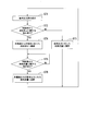
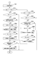
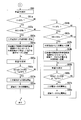
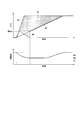
- FIG. 1 is a system diagram of a twin-shaft gas turbine power generation facility according to an embodiment of the present invention. It is a functional block diagram of a control device in one embodiment concerning the present invention. It is a flowchart (the 1) which shows operation
- the twin-shaft gas turbine power generation facility of the present embodiment includes a twin-shaft gas turbine 10, a generator 21, an induction motor 22, a secondary battery 23, an induction motor 22 and an external system 1.
- a first frequency converter 24 that controls transmission / reception of electric power between them, a second frequency converter 25 that controls charging / discharging of the secondary battery 23, and a control device 50.
- the twin-shaft gas turbine 10 includes a compressor 11 that compresses air A to generate compressed air, a combustor 12 that generates fuel gas by burning fuel F in the compressed air, and fuel that is supplied to the combustor 12.
- the fuel control valve 15 which adjusts the flow volume of F, the high-pressure turbine 13 driven with the combustion gas from the combustor 12, and the low-pressure turbine 14 driven with the combustion gas exhausted from the high-pressure turbine 13 are provided.
- the compressor 11 includes a compressor rotor 11r that rotates about the first axis A1 and a compressor casing 11c that covers the compressor rotor 11r.
- the high-pressure turbine 13 includes a high-pressure turbine rotor 13r that rotates about the first axis A1, and a high-pressure turbine casing 13c that covers the high-pressure turbine rotor 13r.
- the compressor rotor 11r and the high-pressure turbine rotor 13r are both located on the first axis A1, and are connected to each other to form the first rotor 17.
- the low-pressure turbine 14 includes a low-pressure turbine rotor 14r that rotates about the second axis A2, and a low-pressure turbine casing 14c that covers the low-pressure turbine rotor 14r.
- the combustor 12 is connected to a fuel supply source by a fuel line 16.
- the fuel line 16 is provided with a fuel adjustment valve 15.
- the induction motor 22 has a motor rotor 22r that rotates about the first axis A1 and a motor casing 22c that covers the motor rotor 22r.
- the motor rotor 22r is mechanically directly connected to the first rotor 17.
- the motor rotor 22r only needs to be mechanically connected to the first rotor 17, and may be mechanically connected to the first rotor 17 via a reduction gear, for example.
- the generator 21 includes a generator rotor 21r that rotates about the second axis A2, and a generator casing 21c that covers the generator rotor 21r.
- This generator 21 is a synchronous generator.
- the generator rotor 21r and the low-pressure turbine rotor 14r are both located on the second axis A2, and are connected to each other to form the second rotor 18.
- the second rotor 18 is not connected to the first rotor 17. For this reason, the second rotor 18 can rotate independently of the rotation of the first rotor 17.
- the generator 21 is electrically connected to the external system 1 through the main power path 31.
- the main power path 31 is provided with a transformer 32 and a circuit breaker 33.
- the induction motor 22 is electrically connected to the external system 1 by a sub power path 34 in parallel with the generator 21.
- the sub power path 34 is connected to a position between the generator 21 and the transformer 32 in the main power path 31.
- the sub power path 34 is provided with a first frequency converter 24, a transformer 35, and a circuit breaker 36.
- the transformer 35 and the circuit breaker 36 are provided closer to the main power path than the first frequency converter 24.
- a second frequency converter 25 is electrically connected to the secondary battery 23.
- the second frequency converter 25 is electrically connected to the external system 1 through a charge / discharge path 37 in parallel with the generator 21 and the induction motor 22. Therefore, the secondary battery 23 is electrically connected to the external system 1 in parallel with the generator 21 and the induction motor 22.
- the charge / discharge path 37 is also connected to a position between the generator 21 and the transformer 32 in the main power path 31, similarly to the sub power path 34.
- the charge / discharge path 37 is provided with a transformer 38 and a circuit breaker 39.
- the first frequency converter 24 converts the frequency of the induction motor 22 into the frequency of the external system 1 when the electric power from the induction motor 22 is transmitted to the external system 1 side. Further, the first frequency converter 24 converts the frequency of the external system 1 into the frequency of the induction motor 22 when receiving power from the external system 1 side and supplying it to the induction motor 22.
- the second frequency converter 25 converts the DC power from the secondary battery 23 into AC power matching the frequency of the external system 1 when discharging the DC power from the secondary battery 23 to the external system 1 side. Further, the second frequency converter 25 converts the AC power of the external system 1 into DC power when the secondary battery 23 is charged with AC power from the external system 1 side.
- the two-shaft gas turbine power generation facility of the present embodiment further includes a rotation speed meter 41 that detects the rotation speed of the induction motor 22, a thermometer 42 that detects the temperature T of the air A sucked by the compressor 11, and a secondary battery. 23 and an ammeter 43 for detecting a current I flowing between the second frequency converter 25 and the second frequency converter 25.
- the motor rotor 22r of the induction motor 22 and the compressor rotor 11r are mechanically connected as described above. For this reason, the rotational speed meter 41 detects the rotational speeds of the induction motor 22 and the compressor 11.
- the control device 50 includes a receiving unit 51 that receives outputs from various meters, various external information, and the like, a determination unit 52 that performs various determinations, and a charge rate SOC (State of the secondary battery 23 Of Charge), a charging rate estimation unit 53, a fuel control unit 54 that controls the opening of the fuel control valve 15, a first control unit 55 that controls the first frequency converter 24, and a second frequency converter.
- a second control unit 56 that controls 25 a storage unit 57 that stores a reference charging rate SOCb of the secondary battery 23, and a reference changing unit 58 that changes the reference charging rate SOCb of the secondary battery 23.
- the reception unit 51 receives a required output DP for the twin-shaft gas turbine power generation facility and a prediction of the temperature of the air A sucked by the compressor 11, that is, a temperature prediction.
- the accepting unit 51 accepts the rotational speed R detected by the rotational speed meter 41, the current value I detected by the ammeter 43, and the temperature T detected by the thermometer 42.
- the receiving unit 51 further receives from the first frequency converter 24 the power amount MP that the induction motor 22 transmits / receives to / from the external system 1 and the power amount that the secondary battery 23 charges / discharges to / from the external system 1.
- BP is received from the second frequency converter 25.
- the charging rate estimation unit 53 estimates the charging rate SOC of the secondary battery 23 based on the current value I detected by the ammeter 43. Specifically, the charging rate estimation unit 53 first sequentially accumulates the accumulated amount of the current value charged / discharged from the secondary battery 23. Then, the integrated amount is subtracted from the full charge amount of the secondary battery 23, and this value is divided by the full charge amount to obtain the charge rate SOC. There are various methods for estimating the charge rate SOC of the secondary battery 23, and any of these methods may be used. For example, the inter-terminal voltage of the secondary battery 23 when the secondary battery 23 is not being charged / discharged may be measured, and the charging rate SOC may be estimated based on the inter-terminal voltage.
- the storage unit 57 stores the reference charging rate SOCb of the secondary battery 23 and the like.
- the reference charging rate SOCb is the charging rate SOC when the secondary battery 23 is charged with, for example, an amount of electric power that is 0.6 times the full charge amount related to the secondary battery 23.
- Reference changing unit 58 changes reference charging rate SOCb stored in storage unit 57.
- the control device 50 is configured by a computer.
- the receiving unit 51 and the control units 54, 55, and 56 are configured by a computer input / output interface, a CPU that performs various calculations, a memory that stores a program executed by the CPU, and the like.
- the determination unit 52, the charging rate estimation unit 53, and the reference change unit 58 are configured by a CPU and a memory of a computer.
- the storage unit 57 includes a computer memory or the like.
- the compressor 11 of the two-shaft gas turbine 10 compresses the air A and supplies the compressed air A to the combustor 12.
- the combustor 12 is supplied with fuel F in addition to the compressed air A.
- the fuel F burns in the compressed air A, and high-temperature and high-pressure combustion gas is generated.
- This combustion gas is sent from the combustor 12 into the high pressure turbine casing 13c, and rotates the high pressure turbine rotor 13r.
- the rotational driving force generated by the high-pressure turbine 13 is used for the rotation of the compressor rotor 11r.
- the combustion gas that has rotated the high-pressure turbine rotor 13r is exhausted from the high-pressure turbine casing 13c and flows into the low-pressure turbine casing 14c.
- This combustion gas rotates the low-pressure turbine rotor 14r. Due to the rotation of the low-pressure turbine rotor 14r, the generator rotor 21r connected to the low-pressure turbine rotor 14r also rotates. As a result, the generator 21 generates power. The electric power from the generator 21 is sent to the external system 1 through the main power path 31.
- the induction motor 22 When starting the biaxial gas turbine 10, the induction motor 22 is driven to rotate the first rotor 17 of the biaxial gas turbine 10.
- the first frequency converter 24 receives power from the external system 1 and sends this power to the induction motor 22.
- the first frequency converter 24 gradually increases the frequency of the power sent to the induction motor 22.
- the rotation speed of the first rotor 17 also increases gradually.
- fuel supply to the combustor 12 is started.
- the fuel supply amount of the combustor 12 is gradually increased.
- control device 50 Next, the operation of the control device 50 will be described with reference to the functional block diagram shown in FIG. 2 and the flowcharts shown in FIGS.
- the receiving unit 51 of the control device 50 always receives the current value I detected by the ammeter 43 (S10: current value receiving step).
- the charging rate estimation unit 53 of the control device 50 integrates the current value I charged / discharged from the secondary battery 23.
- the charge rate estimation unit 53 subtracts the integrated amount of the current value from the full charge amount of the secondary battery 23, and divides this value by the full charge amount to obtain the charge rate SOC (S11: charge rate estimation step).
- the fuel control unit 54 of the control device 50 receives the required output DP for the two-shaft gas turbine power generation facility from the reception unit 51 of the control device 50 via the determination unit 52 (S71: Request output acceptance process). After receiving the request output DP, the fuel control unit 54 determines whether an instruction relating to the fuel flow rate has been received from the determination unit 52 (S72). If the fuel control unit 54 receives the request output DP and does not receive an instruction regarding the fuel flow rate, the fuel control unit 54 determines the fuel flow rate according to the request output DP, and instructs the fuel control valve 15 to determine the opening according to the fuel flow rate. (S73: Fuel control step).
- the maximum output change rate dGPmax is determined with respect to the output change rate of the two-shaft gas turbine 10, that is, the output change rate of the generator 21 from the viewpoint of protection of the high-pressure turbine 13 and the low-pressure turbine 14.
- the output change rate is a change amount of output per unit time.
- the maximum output change rate dGPmax includes a positive maximum output change rate dGPmax when the output increases and a negative maximum output change rate dGPmax when the output decreases.
- the required output change rate dDP also includes a positive required output change rate dDP when the required output DP increases and a negative required output change rate dDP when the required output DP decreases.
- the fuel control unit 54 determines the fuel flow rate so that the generator output GP becomes an output that matches the required output DP. The corresponding opening degree is instructed to the fuel control valve 15.
- the fuel control unit 54 adjusts the fuel flow rate so that the change rate of the generator output GP matches the required output change rate dDP. And the opening degree corresponding to the fuel flow rate is instructed to the fuel control valve 15.
- the fuel control unit 54 sets the change rate of the generator output GP to the maximum output change rate dGPmax of the generator output GP.
- the fuel flow rate is determined so as to match, and the fuel control valve 15 is instructed to open according to the fuel flow rate.
- the fuel control unit 54 does not compare the magnitude relationship between the absolute value of the required output change rate dDP and the absolute value of the maximum output change rate dGPmax of the generator 21, first, the generator output GP becomes the required output DP.
- the fuel flow rate is determined so that the output is appropriate. Thereafter, the fuel control unit 54 limits the rate of change of the fuel flow rate, and instructs the fuel control valve 15 to open an amount corresponding to the limited fuel flow rate.
- the fuel control unit 54 determines the fuel flow rate according to the instruction from the determination unit 52, A corresponding opening degree is instructed to the fuel control valve 15 (S74: fuel control step). Thereafter, the fuel control unit 54 determines whether or not a new instruction regarding the fuel flow rate has been received (S75).
- the fuel control unit 54 determines a fuel flow rate at which the generator output becomes the required output DP in accordance with the new command, and an opening degree corresponding to the fuel flow rate Is instructed to the fuel control valve 15 (S76: fuel control step). The contents of the instruction that the fuel control unit 54 receives from the determination unit 52 will be described later.
- the receiving unit 51 of the control device 50 receives the required output DP for the two-shaft gas turbine power generation facility (S21: required output receiving step).
- the request output DP is sent from the reception unit 51 to the fuel control unit 54 via the determination unit 52 as described above.
- the determination unit 52 of the control device 50 determines whether or not the absolute value of the requested output change rate dDP is larger than the absolute value of the maximum output change rate dGPmax of the generator 21 (S22: first determination step). If the determination unit 52 determines that the absolute value of the required output change rate dDP is not larger than the absolute value of the maximum output change rate dGPmax of the generator 21, that is, the change in the required output DP is not abrupt, the required output change rate dDP is It is determined whether or not 0 (S23). When the determination unit 52 determines that the required output change rate dDP is 0, the output constant process (S60, S61a to S68a, S61b to S68b) described below with reference to FIG. 9 is executed.
- a gradual change process (S40a to S46a) described below with reference to FIGS. , S40b to S46b, S47, S50, S51a to S57a, S51b to S57b, S58, S59) are executed.
- the determination unit 52 determines whether or not the sudden change process for the previous request output DP has ended and the rotation speed R received by the reception unit 51 has returned to the original rotation speed (S25: fourth determination step).
- the sudden change processing for the request output DP is processing of rapid increase processing (S30a to S38a) and rapid decrease processing (S30b to 38b) described below with reference to FIG.
- the original number of rotations is the number of rotations of the compressor 11 and the induction motor 22 at the time of receiving the request output DP whose change is sudden.
- Whether or not the rotation speed R received by the reception unit 51 has returned to the original rotation speed is determined based on the rated rotation speed of the compressor 11 based on the rotation speed R received by the reception unit 51. For example, it is judged by whether or not it is within ⁇ 1%.
- the determination unit 52 determines that the rotation speed R received by the reception unit 51 has returned to the original rotation number, whether or not the rate of change dDP of the request output DP newly received by the reception unit 51 is positive, That is, it is determined whether or not the new request output DP is rapidly increased (S26).
- the determination unit 52 determines that the new request output DP is rapidly increasing, the rapid increase processing (S30a to S38a) shown in FIG. 6 is executed.
- the determination unit 52 determines that the change rate dDP of the new request output DP is not positive, that is, the new request output DP is rapidly decreasing, the rapid decrease processing (S30b to S38b) shown in FIG. 6 is executed. .
- the determination unit 52 determines in S25 that the rotation speed R received by the reception unit 51 has not returned to the original rotation speed, whether or not the change rate dDP of the new request output DP is positive, that is, a new It is determined whether or not the request output DP increases rapidly (S27).
- the determination unit 52 determines whether or not the previous sudden change process was a rapid decrease process (S28: fifth determination step). That is, the determination unit 52 determines whether the sign of the request output change rate dDP of the previous request output DP is opposite to the sign of the request output change rate dDP of the new request output DP.
- a rapid increase process (S30a to S38a) based on the new request output DP is executed. If the determination unit 52 determines that the previous sudden change process was not a rapid decrease process, the process returns to S21.
- the determination unit 52 determines whether or not the previous sudden change process was a rapid increase process ( S29: Fifth determination step). That is, also here, the determination unit 52 determines whether the sign of the request output change rate dDP of the previous request output DP is opposite to the sign of the request output change rate dDP of the new request output DP.
- a rapid decrease process S30b to S38b based on the new request output DP is executed. If the determination unit 52 determines that the previous sudden change process was not a rapid increase process, the process returns to S21.
- this sudden change process includes a rapid increase process (S30a to S38a) and a rapid decrease process (S30b to 38b).
- the rapid increase process (S30a to S38a) is executed when the new request output DP is rapidly increased as described above. However, even when the new required output DP increases rapidly, the rotational speed R of the compressor 11 and the induction motor 22 fluctuates due to a sudden change process with respect to the previous required output DP, and then this rotational speed is the original rotational speed. If the number does not return to the number and the previous sudden change process is a rapid increase process, the rapid increase process (S30a to S38a) is not executed.
- the first control unit 55 causes the first frequency converter 24 to transmit the power MP from the induction motor 22 to the external system 1.
- S30a first control step.
- the first control unit 55 generates the power output MP transmitted from the induction motor 22 to the external system 1 at each time after receiving the new request output DP, and the power MP transmitted from the induction motor 22 at the same time.
- the induction motor 22 has a maximum allowable value related to the power MP transmitted and received by the induction motor 22. That is, the maximum allowable power MPmax is determined for the induction motor 22.
- the determination unit 52 determines whether or not the power MP from the induction motor 22 is the maximum allowable power MPmax (S31a: second determination step). The value of the power MP from the induction motor 22 is sent from the first frequency converter 24 to the control device 50. If the determination unit 52 determines that the power MP from the induction motor 22 has not reached the maximum allowable power MPmax, the process returns to S30a.
- the first control unit 55 uses the first frequency converter 24 as shown in FIG.
- the electric power MP transmitted from the induction motor 22 to the external system 1 is gradually reduced with time (S32a).
- the second control unit 56 uses the second frequency converter 25 to connect from the secondary battery 23 to the external system. 1 is started (S33a: second control step).
- the second control unit 56 sets the generator output GP at each time after the power from the induction motor 22 reaches the maximum allowable power MPmax, and the external from the induction motor 22 at the same time.
- the electric power BP discharged from the secondary battery 23 to the external system 1 is controlled by the device 25.
- the compressor 11 has a permissible rotational speed range from the viewpoint of protecting the compressor 11.
- This allowable rotational speed range is defined by an allowable upper limit rotational speed RpH and an allowable lower limit rotational speed RpL.
- the allowable upper limit rotational speed is a rotational speed that is determined in order to prevent the compressor 11 from rotating excessively (see FIG. 11) and preventing damage to the compressor rotor 11r and its bearings.
- the allowable lower limit rotational speed is higher than the surge rotational speed Rs (see FIG. 10) at which surging occurs in the compressor 11, and is a rotational speed for preventing the occurrence of this surging.
- the determination unit 52 determines whether the rotation speed R is a limit within the allowable rotation speed range, or in this case, whether the rotation speed R is the allowable lower limit rotation speed RpL (S35a: third determination). Process). If the rotation speed R of the first rotor 17 does not reach the allowable lower limit rotation speed RpL, the processes of S34a and S35a are repeated.
- the determination unit 52 determines whether or not the generator output GP is the required output DP after the change (S37a). The determination unit 52 repeats this determination until the generator output GP becomes the required output DP after the change.
- the second control unit 56 stops the discharge of the secondary battery 23 by the second frequency converter 25 (S38a). ).
- this rapid increase process is executed, that is, when it is determined that the required output DP is rapidly increased (S22, S26), as described with reference to FIG.
- a fuel flow rate corresponding to the fuel flow rate is determined, and an opening degree corresponding to the fuel flow rate is instructed to the fuel control valve 15 (S73: fuel control step).
- the fuel control unit 54 determines the fuel flow rate so that the change rate of the generator output GP matches the maximum output change rate dGPmax (positive value) of the generator output GP, and sets the opening according to the fuel flow rate.
- the fuel control valve 15 is instructed.
- the sudden decrease process (S30b to S38b) is executed when the new request output DP is rapidly decreased as described above. However, even when the new required output DP is suddenly decreased, after the rotational speed R of the compressor 11 and the induction motor 22 fluctuates due to the sudden change processing with respect to the previous required output DP, these rotational speeds are restored to the original. If the rotation speed has not been returned and the previous sudden change process is a rapid decrease process, the rapid decrease process (S30b to S38b) is not executed.
- the first control unit 55 supplies the electric power MP received from the external system 1 to the induction motor 22 from the first frequency converter 24.
- S30b first control step.
- the first control unit 55 receives the power from the generator output GP at each time after receiving the new request output DP and the external system 1 at the same time and supplies it to the induction motor 22.
- the power MP supplied to 22 is controlled. For this reason, when the required output DP is rapidly decreasing, the power received from the external system 1 and supplied to the induction motor 22 initially increases with time.
- the determination unit 52 determines whether or not the electric power MP to the induction motor 22, that is, the electric power MP received by the induction motor 22 is the maximum allowable electric power MPmax after the start of power reception for the induction motor 22 (S31b). If the determination unit 52 determines that the power MP received by the induction motor 22 is not the maximum allowable power MPmax, the process returns to S30b.
- the first control unit 55 uses the first frequency converter 24 as shown in FIG.
- the electric power MP received by the induction motor 22 is gradually reduced as time passes (S32b).
- the second control unit 56 uses the second frequency converter 25 to apply power to the secondary battery 23. Charging is started (S33b: second control step).
- the second control unit 56 determines that the induction motor 22 at the same time is based on the generator output GP at each time after the power MP received by the induction motor 22 reaches the maximum allowable power MPmax.
- the second frequency converter 25 controls the charging power BP of the secondary battery 23 so that the value obtained by subtracting the received power MP and the charging power BP of the secondary battery 23 at the same time becomes the required output DP at the same time.
- the power MP received by the induction motor 22 is a negative value and the charging power BP of the secondary battery 23 is handled as a negative value, the power MP received by the induction motor 22 has reached the maximum allowable power MPmax.
- a value obtained by adding the generator output GP at each subsequent time, the power MP received by the induction motor 22 at the same time, and the charging power BP of the secondary battery 23 at the same time becomes the required output DP at the same time.
- the charging power BP of the secondary battery 23 is controlled by the second frequency converter 25.
- the determination unit 52 determines whether or not the rotational speed R is a limit within the allowable rotational speed range, and in this case, the rotational speed R is an allowable upper limit rotational speed RpH (S35b: third determination). Process). If the rotation speed R of the first rotor 17 does not reach the allowable upper limit rotation speed RpH, the processes of S34b and S35b are repeated.
- the determination unit 52 determines whether or not the generator output GP is the required output DP after the change (S37b). The determination unit 52 repeats this determination until the generator output GP becomes the required output DP after the change.
- the second control unit 56 stops the charging of the secondary battery 23 by the second frequency converter 25 (S38b). ).
- the secondary battery 23 when the absolute value of the required output change rate dDP is larger than the absolute value of the maximum output change rate dGPmax, the secondary battery 23 is used after the power transmitted and received by the induction motor 22 reaches the maximum allowable power MPmax. To charge and discharge. That is, in the present embodiment, even if the absolute value of the required output change rate dDP becomes larger than the absolute value of the maximum output change rate dGPmax, the secondary battery 23 is not charged / discharged immediately. Therefore, in the present embodiment, the number of times of charging / discharging the secondary battery 23 can be reduced, and the life extension can be achieved by suppressing the performance deterioration of the secondary battery 23.
- the power transmitted and received by the induction motor 22 during the power transmission / reception to the induction motor 22 is increased.
- the maximum allowable power MPmax is reached, the secondary battery 23 is charged and discharged. Therefore, in this embodiment, the continuity of the power transmission / reception with respect to the external system 1 by the power transmission / reception of the induction motor 22 and the charge / discharge of the secondary battery 23 is ensured.
- the power MP transmitted and received by the induction motor 22 by the determination unit 52 after the absolute value of the required output change rate dDP is determined to be larger than the absolute value of the maximum output change rate dGPmax is the maximum allowable power MPmax.
- the amount of power transmitted to and received from the induction motor 22 increases until it is determined that the output of the two-shaft gas turbine power generation facility can follow the change in the required output DP during this period.
- the switching lower limit number of rotations RcL is higher than the allowable lower limit number of rotations RpL.
- the switching upper limit number RcH is a rotational speed lower than the allowable upper limit rotational speed RpH.
- the determination part 52 determines whether the rotation speed R of the 1st rotor 17 is the switching upper limit rotation speed RcH.
- the first control unit 55 uses the first frequency converter 24 as shown in FIG. Then, the electric power MP received by the induction motor 22 is gradually reduced with time (S32b).
- the determination unit 52 determines whether the power of the power transmission / reception with respect to the induction motor 22 is the maximum allowable power MPmax or whether the first rotor 17 It may be determined whether or not the rotational speed is a limit within the switching rotational speed range.
- the rapid increase process for the new request process is not executed, and the process returns to S21. For this reason, in this embodiment, even if the previous sudden change process is a rapid increase process and a new request process is received at a stage where the rapid increase process has not ended, the previous rapid increase process is continued. However, in S74, the fuel flow rate is adjusted according to the new required output DP. If the previous sudden change process is a rapid increase process and a new request process is received at a stage where the rapid increase process has not ended, the previous rapid increase process may be stopped.
- the rapid decrease process for the new request process is not executed, and the process returns to S21.
- the previous sudden change process is a rapid decrease process, and even if a new request process is received at a stage where the sudden decrease process has not been completed, the previous rapid decrease process is continued.
- the fuel flow rate is adjusted according to the new required output DP. If the previous sudden change process is a sudden decrease process and a new request process is received at a stage where the sudden decrease process has not been completed, the previous sudden decrease process may be stopped.
- this gradual change process is executed when it is determined that the change in the required output DP is gradual (NO in S22 and NO in S23).
- the determination unit 52 determines whether or not the required output DP becomes a set low output lower than the rated generator output GPr (S40a: ninth determination step).
- the set low output is, for example, an output that is 0.5 times the rated generator output GPr.
- the determining unit 52 determines whether or not the charging rate SOC estimated by the charging rate estimating unit is lower than the set high charging rate higher than the reference charging rate SOCb ( S41a: Sixth determination step).
- the set high charge rate is, for example, a charge rate SOC that is 1.3 times the reference charge rate SOCb. If the determination unit 52 determines that the charging rate SOC is not less than the set high charging rate, the gradual change process ends. In addition, when determining that the charging rate SOC is less than the set high charging rate, the determining unit 52 determines whether or not the required output change rate dDP is negative (S42a: first determining step).
- the determination unit 52 determines that the required output change rate dDP is not negative, the gradual change process ends.
- the second control unit 56 charges the secondary battery 23 with the second frequency converter 25 (S43a: second control step). .
- the fuel control unit 54 receives the instruction from the determination unit 52 (S 72), and follows the instruction from the determination unit 52.
- a fuel flow rate is determined, and an opening degree corresponding to the fuel flow rate is instructed to the fuel control valve 15 (S74: fuel control step).
- the determination unit 52 determines whether or not the charging rate SOC is the set high charging rate (S45a). If charge rate SOC is not the set high charge rate, determination unit 52 waits until charge rate SOC reaches the set high charge rate. When the determination unit 52 determines that the charging rate SOC is the set high charging rate, the second control unit 56 ends the charging of the secondary battery 23 by the second frequency converter 25 (S46a). Then, the determination unit 52 instructs the fuel control unit 54 so that the generator output GP becomes the required output DP (S47). As described with reference to FIG.
- the fuel control unit 54 determines the fuel flow rate according to the instruction from the determination unit 52, and sets the opening according to the fuel flow rate.
- the fuel control valve 15 is instructed (S76: fuel control process). In this case, the fuel control unit 54 determines the fuel flow rate at which the generator output GP becomes the required output DP.
- the determination unit 52 determines in S40a that the required output DP does not become a set low output lower than the rated generator output GPr, the required output DP is set lower than the rated generator output GPr and higher than the set low output. (S40b: Ninth determination step).
- the set high output is, for example, an output 0.9 times the rated generator output GPr.
- the determining unit 52 determines whether or not the charging rate SOC estimated by the charging rate estimating unit 53 is higher than a set low charging rate lower than the reference charging rate SOCb ( S41b: Sixth determination step).
- the set low charge rate is, for example, a charge rate SOC that is 0.7 times the reference charge rate SOCb. If the determination unit 52 determines that the charging rate SOC is not higher than the set low charging rate, the gradual change process ends. Further, when determining unit 52 determines that the charging rate SOC is higher than the set low charging rate, it determines whether or not the rate of change of requested output DP is positive (S42b: first determining step).
- the second control unit 56 causes the second frequency converter 25 to discharge the power MP from the secondary battery 23 to the external system 1. (S43b: second control step). Then, the determination unit 52 instructs the fuel control unit 54 so that the generator output GP becomes a value obtained by subtracting the power to be discharged from the secondary battery 23 from the required output DP (S44b). As described with reference to FIG. 4, after receiving the request output from the determination unit 52 (S 71), the fuel control unit 54 receives the instruction from the determination unit 52 (S 72), and follows the instruction from the determination unit 52.
- a fuel flow rate is determined, and an opening degree corresponding to the fuel flow rate is instructed to the fuel control valve 15 (S74: fuel control step).
- the fuel control unit 54 determines the fuel flow rate at which the generator output GP is a value obtained by subtracting the power discharged from the secondary battery 23 from the required output DP. Therefore, the fuel control unit 54 makes the fuel flow rate smaller than the fuel flow rate when all of the required output DP is secured by the generator output GP.
- the determination unit 52 determines whether or not the charging rate SOC is a set low charging rate (S45b). If charge rate SOC is not the set low charge rate, determination unit 52 waits until charge rate SOC reaches the set low charge rate. When the determination unit 52 determines that the charging rate SOC is the set low charging rate, the second control unit 56 stops the discharge of the secondary battery 23 by the second frequency converter 25 (S46b). Then, as described above, the determination unit 52 instructs the fuel control unit 54 so that the generator output GP becomes the required output DP (S47).
- the reception unit 51 receives a temperature forecast (S50: temperature forecast reception step).
- the determination unit 52 determines whether or not the charge rate SOC estimated by the charge rate estimation unit 53 is lower than the set low charge rate (S51a: sixth determination step). When determining that the charging rate SOC is lower than the set low charging rate, the determining unit 52 determines whether the required output change rate dDP is negative (S52a: first determining step). When the determination unit 52 determines that the required output change rate dDP is not negative, the gradual change process ends. When determining that the required output change rate dDP is negative, the determining unit 52 determines whether or not the temperature after X hours is higher than the first temperature (S53a: eighth determining step). This X hour is, for example, 6 hours later.
- the first temperature is a temperature higher than the design temperature of the air sucked by the compressed air, and is 30 ° C., for example.
- the reference changing unit 58 increases the reference charging rate SOCb (S54a: reference changing step). Specifically, a charging rate SOC obtained by multiplying the reference charging rate SOCb as an initial value by 1.3, for example, is set as a new reference charging rate SOCb.
- the second control unit 56 charges the secondary battery 23 with the second frequency converter 25 (S55a: second control step).
- the determination unit 52 determines that the temperature after X hours does not become higher than the first temperature in S53a
- the second control unit 56 immediately charges the secondary battery 23 with the second frequency converter 25. (S55a).
- the determination unit 52 determines whether or not the charging rate SOC is the reference charging rate SOCb (S56a). If charge rate SOC is not equal to reference charge rate SOCb, determination unit 52 waits until charge rate SOC reaches reference charge rate SOCb. When the determination unit 52 determines that the charging rate SOC is equal to the reference charging rate SOCb, the second control unit 56 stops the charging of the secondary battery 23 by the second frequency converter 25 (S57a).
- the determination unit 52 determines whether or not the reference charging rate SOCb is an initial value (S58).
- reference changing unit 58 returns reference charging rate SOCb to the original initial value.
- the gradual change process ends.
- the determination unit 52 determines that the reference charging rate SOCb is the initial value, the gradual change process is immediately terminated.
- the change in the required output DP is gradually reduced and the charging rate SOC of the secondary battery 23 is low, the power from the external system 1 is charged in the secondary battery 23.
- the determination unit 52 determines whether or not the charging rate SOC is higher than the set high charging rate (S51b: sixth determination step). If the determination unit 52 determines that the charging rate SOC is not higher than the set high charging rate, the gradual change process ends. When determining that the charging rate SOC is higher than the set high charging rate, the determining unit 52 determines whether or not the required output change rate dDP is positive (S52b: first determining step). When the determination unit 52 determines that the required output change rate dDP is not positive, the gradual change process ends.
- the determination unit 52 determines whether or not the temperature after X hours is lower than the second temperature (S53b: eighth determination step).
- This second temperature is a temperature lower than the design temperature of the air sucked by the compressed air, and is 10 ° C., for example. If the determination unit 52 determines that the temperature after X hours is lower than the second temperature, the reference changing unit 58 decreases the reference charging rate SOCb (S54b: reference changing step). Specifically, for example, a charging rate SOC obtained by multiplying the reference charging rate SOCb as an initial value by 0.7 is used as a new reference charging rate SOCb.
- the second control unit 56 causes the second frequency converter 25 to discharge power from the secondary battery 23 (S55b: second control step).
- the determination unit 52 determines that the temperature after X hours is not lower than the second temperature in S53b
- the second control unit 56 immediately uses the second frequency converter 25 to supply power from the secondary battery 23. Discharge (S55b).
- the determination unit 52 determines whether or not the charging rate SOC is the reference charging rate SOCb (S56b). If charge rate SOC is not equal to reference charge rate SOCb, determination unit 52 waits until charge rate SOC reaches reference charge rate SOCb. When the determination unit 52 determines that the charging rate SOC is equal to the reference charging rate SOCb, the second control unit 56 stops the discharge from the secondary battery 23 by the second frequency converter 25 (S57b).
- the determination unit 52 determines whether or not the reference charging rate SOCb is an initial value (S58).
- reference changing unit 58 returns reference charging rate SOCb to the original initial value (S59).
- the gradual change process ends.
- the determination unit 52 determines that the reference charging rate SOCb is the initial value, the gradual change process is immediately terminated.
- the change in the required output DP gradually increases and the charging rate SOC of the secondary battery 23 is high, the secondary battery 23 is discharged to the external system 1.
- This output constant time process is executed when it is determined that the change rate of the requested output DP is 0 as described above (in the case of YES in S23).
- the reception unit 51 receives the temperature of the air detected by the thermometer 42, that is, the temperature T (S60: temperature reception step).
- the determination unit 52 determines whether or not the temperature T is higher than the first temperature (for example, 30 ° C.) (S61a: seventh determination step).
- the determination unit 52 determines whether or not the charging rate SOC of the secondary battery 23 is higher than the reference charging rate SOCb (S62a: sixth determination step). If determination unit 52 determines that charging rate SOC of secondary battery 23 is not higher than reference charging rate SOCb, the process when the output is constant ends.
- the reception unit 51 receives the temperature T detected by the thermometer 42 (S65a).
- the determination unit 52 determines whether the temperature T is equal to or lower than the first temperature (for example, 30 ° C.) or the charging rate SOC is a set low charging rate (for example, a charging rate SOC that is 0.7 times the reference charging rate SOCb). It is determined whether the following is true (S66a). When the temperature T is not lower than the first temperature (for example, 30 ° C.) and the charging rate SOC is not lower than the set low charging rate, the process returns to S65a.
- the second control unit 56 is configured to use the second frequency converter 25.
- the discharge from the secondary battery 23 to the external system 1 is stopped (S67a).
- the first control unit 55 stops the supply of the electric power received from the external system 1 to the induction motor 22 by the first frequency converter 24 (S68a).
- the process ends when the output is constant. Note that when this output constant processing is executed, as described with reference to FIG. 4, the fuel control unit 54 determines the fuel flow rate according to the required output DP and sets the opening according to the fuel flow rate to the fuel flow. The control valve 15 is instructed (S73: fuel control process).
- the present embodiment when the temperature of the air sucked by the compressor 11, that is, the temperature T is high, the power of the secondary battery 23 is discharged and the induction motor 22 is driven using this power. The drive of the compressor 11 is assisted. Therefore, in this embodiment, even when the temperature of the air which the compressor 11 inhales is high, the fall of the generator output GP can be suppressed.
- the reference charging rate SOCb of the secondary battery 23 is increased. Then, the secondary battery 23 is charged by the second frequency converter 25 so that the charging rate SOC of the secondary battery 23 becomes the reference charging rate SOCb. Therefore, in the present embodiment, when the temperature of the air sucked by the compressor 11 is high and the secondary battery 23 is discharged and the drive of the compressor 11 is assisted by the induction motor 22, the charging rate SOC of the secondary battery 23 in advance. Can be raised. For this reason, the drive of the compressor 11 can be assisted by the induction motor 22 for a long time.
- the determination part 52 determines in S61a that the temperature T is not higher than the first temperature (for example, 30 ° C.), it is determined whether or not the temperature T is lower than the second temperature (for example, 10 ° C.) (S61b). : Seventh judgment step). When the determination unit 52 determines that the temperature T is not lower than the second temperature, the process is terminated when the output is constant. Further, when determining that the temperature T is lower than the second temperature, the determination unit 52 determines whether or not the charging rate SOC of the secondary battery 23 is lower than the reference charging rate SOCb (S62b: sixth determination step). If determination unit 52 determines that charging rate SOC of secondary battery 23 is not lower than reference charging rate SOCb, the process when the output is constant ends.
- the second control unit 56 supplies the power received from the external system 1 by the second frequency converter 25 to the second level.
- the secondary battery 23 is supplied (S63b).
- the first control unit 55 uses the first frequency converter 24 to transfer the electric power from the induction motor 22 to the external system. 1 is transmitted (S64b).
- the electric power from the induction motor 22 is transmitted to the external system 1.
- the reception unit 51 receives the temperature T detected by the thermometer 42 (S65b).
- the determination unit 52 determines whether the temperature T is equal to or higher than the second temperature (for example, 10 ° C.) or the charging rate SOC is a set high charging rate (for example, a charging rate SOC that is 1.3 times the reference charging rate SOCb). It is determined whether the above is true (S66b).
- the process returns to S65b.
- the second control unit 56 sends the secondary battery 23 to the second frequency converter 25. Is stopped (S67b).
- the 1st control part 55 stops the transmission of the electric power from the induction motor 22 to the external system
- the induction motor 22 is driven by the compressor 11, that is, the induction motor 22 assists the driving of the compressor 11 to the negative side.
- the electric power from the motor 22 is transmitted to the external system 1 and the secondary battery 23 is charged with the electric power. Therefore, in this embodiment, even when the temperature of the air which the compressor 11 inhales is low, the raise of the generator output GP can be suppressed.
- the reference charging rate SOCb of the secondary battery 23 is decreased. After that, the secondary battery 23 is discharged to the secondary battery 23 by the second frequency converter 25 so that the charge rate SOC of the secondary battery 23 becomes the reference charge rate SOCb. Therefore, in this embodiment, when the temperature of the air sucked by the compressor 11 becomes low, the charge amount to the secondary battery 23 can be increased in S63b (see FIG. 9).
- the induction motor 22 is electrically connected to the external system 1 via the sub power path 34 and the main power path 31.
- the secondary battery 23 is electrically connected to the external system 1 through the charge / discharge path 37 and the main power path 31.
- the induction motor 22 may be electrically connected to the external system 1 via the sub power path 34 instead of the main power path 31.
- the secondary battery 23 may be electrically connected to the external system 1 via the charge / discharge path 37 instead of via the main power path 31.
- the followability of the output of the twin-shaft gas turbine power generation facility with respect to a required output change can be improved, and the life of the secondary battery can be extended by suppressing the performance degradation of the secondary battery. Can do.
Landscapes
- Engineering & Computer Science (AREA)
- Chemical & Material Sciences (AREA)
- Combustion & Propulsion (AREA)
- Mechanical Engineering (AREA)
- General Engineering & Computer Science (AREA)
- Power Engineering (AREA)
- Control Of Eletrric Generators (AREA)
- Supply And Distribution Of Alternating Current (AREA)
- Fuel Cell (AREA)
Abstract
La présente invention concerne une installation de turbine à gaz à deux arbres comportant : une turbine à gaz à deux arbres (10) ; un moteur à induction (22) couplé à un compresseur (11) de la turbine à gaz à deux arbres (10) ; une batterie secondaire (23) ; un premier convertisseur de fréquence (24) qui commande un échange d'énergie électrique entre un système externe (1) et le moteur à induction (22) ; et un second convertisseur de fréquence (25) qui commande la charge et la décharge de l'énergie électrique entre la batterie secondaire (23) et le système externe (1). Une première unité de commande (55) d'un dispositif de commande (50) amène le premier convertisseur de fréquence (24) à échanger de l'électricité entre le moteur à induction (22) et le système externe (1) si une vitesse de changement demandée de sortie est supérieure à une vitesse maximale de changement de sortie. Une seconde unité de commande (56) amène la batterie secondaire (23) à être chargée ou déchargée par le second convertisseur de fréquence (25) si la quantité d'énergie échangée par le moteur à induction (22) est une puissance maximale admissible.
Priority Applications (4)
| Application Number | Priority Date | Filing Date | Title |
|---|---|---|---|
| US16/319,716 US10637341B2 (en) | 2016-07-22 | 2017-07-21 | Two-shaft gas turbine power generating facility and control method for same |
| CN201780044500.7A CN109478861B (zh) | 2016-07-22 | 2017-07-21 | 双轴燃气轮机发电设备及其控制方法 |
| KR1020197001737A KR102104217B1 (ko) | 2016-07-22 | 2017-07-21 | 2축 가스 터빈 발전 설비, 및 그 제어 방법 |
| DE112017003686.0T DE112017003686T5 (de) | 2016-07-22 | 2017-07-21 | Zweiwellengasturbinenenergieerzeugungsanlage und steuerverfahren hierfür |
Applications Claiming Priority (2)
| Application Number | Priority Date | Filing Date | Title |
|---|---|---|---|
| JP2016144230A JP6288529B2 (ja) | 2016-07-22 | 2016-07-22 | 二軸ガスタービン発電設備、及びその制御方法 |
| JP2016-144230 | 2016-07-22 |
Publications (1)
| Publication Number | Publication Date |
|---|---|
| WO2018016623A1 true WO2018016623A1 (fr) | 2018-01-25 |
Family
ID=60992617
Family Applications (1)
| Application Number | Title | Priority Date | Filing Date |
|---|---|---|---|
| PCT/JP2017/026460 Ceased WO2018016623A1 (fr) | 2016-07-22 | 2017-07-21 | Installation de production d'énergie à turbine à gaz à deux arbres et son procédé de commande |
Country Status (7)
| Country | Link |
|---|---|
| US (1) | US10637341B2 (fr) |
| JP (1) | JP6288529B2 (fr) |
| KR (1) | KR102104217B1 (fr) |
| CN (1) | CN109478861B (fr) |
| DE (1) | DE112017003686T5 (fr) |
| TW (1) | TWI663830B (fr) |
| WO (1) | WO2018016623A1 (fr) |
Families Citing this family (8)
| Publication number | Priority date | Publication date | Assignee | Title |
|---|---|---|---|---|
| JP6976191B2 (ja) * | 2018-02-22 | 2021-12-08 | 三菱パワー株式会社 | 二軸ガスタービン発電設備、その制御装置、及びその制御方法 |
| CN111799817B (zh) * | 2019-04-01 | 2024-05-10 | 斗山重工业建设有限公司 | 发电站连接型能量存储系统及其控制方法 |
| DE102019128387A1 (de) * | 2019-10-21 | 2021-04-22 | Torqeedo Gmbh | Generatorsatz zum Erzeugen eines Wechselstromes |
| US11428171B2 (en) * | 2019-12-06 | 2022-08-30 | General Electric Company | Electric machine assistance for multi-spool turbomachine operation and control |
| CN112502833A (zh) * | 2020-11-18 | 2021-03-16 | 靳新中 | 双轴发电燃气轮机 |
| JP7841903B2 (ja) * | 2022-02-28 | 2026-04-07 | 本田技研工業株式会社 | パワーユニットシステムの制御装置 |
| US12480449B2 (en) | 2022-08-22 | 2025-11-25 | General Electric Company | Propulsion system including an electric machine for starting a gas turbine engine |
| US20250266739A1 (en) * | 2024-02-20 | 2025-08-21 | Imperial Industrial Supply Co. | Hybrid generator |
Citations (6)
| Publication number | Priority date | Publication date | Assignee | Title |
|---|---|---|---|---|
| JP2005245105A (ja) * | 2004-02-25 | 2005-09-08 | Kawasaki Heavy Ind Ltd | ガスエンジン発電設備 |
| JP2006169995A (ja) * | 2004-12-14 | 2006-06-29 | Takuma Co Ltd | マイクロガスタービン発電システム及び捕機電力供給方法 |
| US20060150633A1 (en) * | 2003-12-18 | 2006-07-13 | Honeywell International Inc. | Starting and controlling speed of a two spool gas turbine engine |
| WO2014020772A1 (fr) * | 2012-08-03 | 2014-02-06 | 株式会社日立製作所 | Système de production de puissance à turbine à gaz à deux arbres, et dispositif de commande et procédé de commande pour système de turbine à gaz |
| WO2015181938A1 (fr) * | 2014-05-30 | 2015-12-03 | 株式会社日立製作所 | Dispositif de production d'énergie composite de turbine à gaz |
| WO2016098220A1 (fr) * | 2014-12-18 | 2016-06-23 | 株式会社日立製作所 | Système de génération d'énergie à turbine à gaz, procédé de commande pour système de génération d'énergie à turbine à gaz, et dispositif de commande pour système de génération d'énergie à turbine à gaz |
Family Cites Families (14)
| Publication number | Priority date | Publication date | Assignee | Title |
|---|---|---|---|---|
| WO1998025014A2 (fr) * | 1996-12-03 | 1998-06-11 | Elliott Energy Systems, Inc. | Systeme electrique de turboalternateur sur arbre commun |
| US6931856B2 (en) | 2003-09-12 | 2005-08-23 | Mes International, Inc. | Multi-spool turbogenerator system and control method |
| FR2914697B1 (fr) * | 2007-04-06 | 2012-11-30 | Turbomeca | Dispositif d'assistance aux phases transitoires d'acceleration et de deceleration |
| JP4726930B2 (ja) * | 2008-07-10 | 2011-07-20 | 株式会社日立製作所 | 2軸式ガスタービン |
| JP2010168957A (ja) * | 2009-01-21 | 2010-08-05 | Hitachi Ltd | 2軸式ガスタービンと、2軸式ガスタービン用の燃焼器の予混合燃焼開始方法 |
| JP5640227B2 (ja) * | 2011-02-04 | 2014-12-17 | 三菱日立パワーシステムズ株式会社 | ガスタービン発電プラントの制御装置 |
| JP5639568B2 (ja) | 2011-11-15 | 2014-12-10 | 三菱日立パワーシステムズ株式会社 | 2軸式ガスタービン |
| JP5675675B2 (ja) * | 2012-02-29 | 2015-02-25 | 三菱重工業株式会社 | コンバインド発電システム、及びコンバインド発電システムの運転方法 |
| JP5876153B2 (ja) | 2012-06-29 | 2016-03-02 | 株式会社日立製作所 | 火力発電設備、自然エネルギー発電プラント及びその制御方法 |
| CN103051268A (zh) * | 2012-12-12 | 2013-04-17 | 北京动力机械研究所 | 一种微型燃气轮机发电集成控制系统 |
| ITFI20120292A1 (it) * | 2012-12-24 | 2014-06-25 | Nuovo Pignone Srl | "gas turbines in mechanical drive applications and operating methods" |
| JP6101787B2 (ja) | 2013-03-29 | 2017-03-22 | 株式会社日立製作所 | 発電システムおよび発電システムの制御方法 |
| CN105281624B (zh) * | 2014-06-17 | 2021-04-06 | 松下知识产权经营株式会社 | 热动力发电装置和热动力发电系统 |
| JP2016144230A (ja) | 2015-01-29 | 2016-08-08 | トヨタ自動車株式会社 | 回転電機ステータ |
-
2016
- 2016-07-22 JP JP2016144230A patent/JP6288529B2/ja active Active
-
2017
- 2017-07-21 CN CN201780044500.7A patent/CN109478861B/zh not_active Expired - Fee Related
- 2017-07-21 DE DE112017003686.0T patent/DE112017003686T5/de active Pending
- 2017-07-21 KR KR1020197001737A patent/KR102104217B1/ko not_active Expired - Fee Related
- 2017-07-21 US US16/319,716 patent/US10637341B2/en active Active
- 2017-07-21 TW TW106124993A patent/TWI663830B/zh not_active IP Right Cessation
- 2017-07-21 WO PCT/JP2017/026460 patent/WO2018016623A1/fr not_active Ceased
Patent Citations (6)
| Publication number | Priority date | Publication date | Assignee | Title |
|---|---|---|---|---|
| US20060150633A1 (en) * | 2003-12-18 | 2006-07-13 | Honeywell International Inc. | Starting and controlling speed of a two spool gas turbine engine |
| JP2005245105A (ja) * | 2004-02-25 | 2005-09-08 | Kawasaki Heavy Ind Ltd | ガスエンジン発電設備 |
| JP2006169995A (ja) * | 2004-12-14 | 2006-06-29 | Takuma Co Ltd | マイクロガスタービン発電システム及び捕機電力供給方法 |
| WO2014020772A1 (fr) * | 2012-08-03 | 2014-02-06 | 株式会社日立製作所 | Système de production de puissance à turbine à gaz à deux arbres, et dispositif de commande et procédé de commande pour système de turbine à gaz |
| WO2015181938A1 (fr) * | 2014-05-30 | 2015-12-03 | 株式会社日立製作所 | Dispositif de production d'énergie composite de turbine à gaz |
| WO2016098220A1 (fr) * | 2014-12-18 | 2016-06-23 | 株式会社日立製作所 | Système de génération d'énergie à turbine à gaz, procédé de commande pour système de génération d'énergie à turbine à gaz, et dispositif de commande pour système de génération d'énergie à turbine à gaz |
Also Published As
| Publication number | Publication date |
|---|---|
| JP6288529B2 (ja) | 2018-03-07 |
| US20190280583A1 (en) | 2019-09-12 |
| CN109478861B (zh) | 2021-10-08 |
| JP2018014858A (ja) | 2018-01-25 |
| DE112017003686T5 (de) | 2019-04-04 |
| KR102104217B1 (ko) | 2020-04-23 |
| KR20190019182A (ko) | 2019-02-26 |
| TWI663830B (zh) | 2019-06-21 |
| CN109478861A (zh) | 2019-03-15 |
| TW201818647A (zh) | 2018-05-16 |
| US10637341B2 (en) | 2020-04-28 |
Similar Documents
| Publication | Publication Date | Title |
|---|---|---|
| JP6288529B2 (ja) | 二軸ガスタービン発電設備、及びその制御方法 | |
| JP5167106B2 (ja) | 風力発電所とその発電制御方法 | |
| US8487561B2 (en) | Softstarter device and method to control the softstarting of an electric motor | |
| JP7132584B2 (ja) | 交流電動機の始動と運転のための装置 | |
| KR101813430B1 (ko) | 복합 발전 플랜트, 그 제어 방법, 및 그 제어 장치 | |
| WO2009116495A1 (fr) | Procédé et dispositif pour déterminer l'état de dégradation d'un dispositif de stockage dans un équipement de construction hybride | |
| CN102332850B (zh) | 一种电机在旋转中再启动的控制方法 | |
| JP7412309B2 (ja) | 系統併入装置 | |
| CN104395164B (zh) | 用于混合动力施工机械的使用风扇的旋转力的电池充电系统和其充电方法 | |
| WO2017110437A1 (fr) | Dispositif d'estimation de capacité résiduelle de batterie lithium-ion | |
| CN104365009A (zh) | 电动机控制装置 | |
| JP4947926B2 (ja) | 電力貯蔵手段を具備した自家発電設備の運転方法及び自家発電設備 | |
| JP2009085047A (ja) | 圧縮装置及びその制御方法 | |
| WO2018198756A1 (fr) | Générateur de stockage d'énergie à air comprimé | |
| WO2019176004A1 (fr) | Climatiseur | |
| CN116157588A (zh) | 联合循环机组、联合循环机组的启动方法、以及用于执行该方法的启动控制程序 | |
| JP2015089331A (ja) | 電力供給ネットワークに接続された発電機の運転方法 | |
| JP5048548B2 (ja) | インバータ式エンジン発電装置 | |
| JP2012066786A (ja) | ハイブリッド建設機械のエンジン始動制御装置 | |
| CN106006342B (zh) | 自动扶梯由电网驱动切换至变频驱动的控制方法及装置 | |
| JP2016100288A (ja) | 建設機械 | |
| CN102939711A (zh) | 预测同步发电机的瞬态稳定性的方法和相关设备 | |
| JP5371260B2 (ja) | インバータ式エンジン発電装置 | |
| US20250164560A1 (en) | Power generation system and control method | |
| JP2000308393A (ja) | 可変周波数駆動電動機の急速昇速装置およびバックアップ装置 |
Legal Events
| Date | Code | Title | Description |
|---|---|---|---|
| 121 | Ep: the epo has been informed by wipo that ep was designated in this application |
Ref document number: 17831139 Country of ref document: EP Kind code of ref document: A1 |
|
| ENP | Entry into the national phase |
Ref document number: 20197001737 Country of ref document: KR Kind code of ref document: A |
|
| 122 | Ep: pct application non-entry in european phase |
Ref document number: 17831139 Country of ref document: EP Kind code of ref document: A1 |