WO2018024558A1 - Cooking appliance with improved side wire racks - Google Patents
Cooking appliance with improved side wire racks Download PDFInfo
- Publication number
- WO2018024558A1 WO2018024558A1 PCT/EP2017/068833 EP2017068833W WO2018024558A1 WO 2018024558 A1 WO2018024558 A1 WO 2018024558A1 EP 2017068833 W EP2017068833 W EP 2017068833W WO 2018024558 A1 WO2018024558 A1 WO 2018024558A1
- Authority
- WO
- WIPO (PCT)
- Prior art keywords
- cooking appliance
- wire
- cavity
- retaining member
- side wire
- Prior art date
- Legal status (The legal status is an assumption and is not a legal conclusion. Google has not performed a legal analysis and makes no representation as to the accuracy of the status listed.)
- Ceased
Links
Images



Classifications
-
- F—MECHANICAL ENGINEERING; LIGHTING; HEATING; WEAPONS; BLASTING
- F24—HEATING; RANGES; VENTILATING
- F24C—DOMESTIC STOVES OR RANGES ; DETAILS OF DOMESTIC STOVES OR RANGES, OF GENERAL APPLICATION
- F24C15/00—Details
- F24C15/16—Shelves, racks or trays inside ovens; Supports therefor
Definitions
- the present invention relates to a cooking appliance, in particular to a cooking appliance which has an oven.
- a cooking appliance generally comprises a cavity for cooking the food; a pair of side wire racks which are disposed onto the side walls of the cavity respectively, and adapted to support a tray at one or more different levels, wherein the side wire racks each comprises one or more wires and mounting tabs welded to the wires; and one or more fixing devices for fixing the mounting tabs to the side walls of the cavity.
- the user places the food to be cooked onto the tray and mounts it into the cavity by means of the side wire racks.
- US 2013/0118471 A1 discloses an oven with a microwave heating function.
- a problem with the prior art cooking appliance is that the production of the side wire racks and the assemblage of the side wire racks with the cavity is cost-intensive both in terms of labor and material. Another problem with the prior art cooking appliance is that the side wire racks can easily vibrate during the transportation and fall out. Another problem with the prior art cooking appliance is that the tray can get stuck in the side wire racks when mounting or removing the tray.
- An objective of the present invention is to provide a cooking appliance which solves the aforementioned problems of the prior art in a cost-effective way and which enables an improved production and assemblage and an improved usability.
- each side wire rack comprises three bending wire sections which are adapted to form-fittingly engage with the fixing devices respectively.
- a major advantageous effect of the present invention is that the side wire racks can be easily manufactured and assembled with the cavity.
- the need for the prior art mounting tabs has been obviated, and thus the production costs have been decreased both in terms of material and labor.
- Another major advantageous effect of the present invention is that the risk that the side wire racks vibrate or fall out can be eliminated or reduced as much as possible by virtue of the form-fitting engagement between the fixing devices and the side wire racks.
- Another major advantageous effect of the present invention is that the side wire racks can be prevented from deformations during the assemblage by virtue of the three-point engagement between side wire racks and the side walls. Thereby, the risk that the trays get stuck in the side wire racks when mounting removing the same can be eliminated or reduced as much as possible.
- each fixing device has a heat resistant and electrically insulating retaining member which keeps the respective side wire rack at an electrically safe distance from the side wall.
- the retaining member is manufactured from ceramic. This embodiment is particularly advantageous as the risk of spark generation at the side wire racks within the cavity has been eliminated or reduced as much as possible by virtue of the retaining remember. Thereby, the leakage of the microwave radiation to the outside of the cavity via the side wire racks has been eliminated. Thereby, also the cooking efficiency and the safety of the cooking appliance have been improved.
- the bending wire section is fitted around a groove in the retaining member during the assemblage.
- the groove is circular shaped, and the bending wire section is semicircular shaped. This embodiment is particularly advantageous as the side wire racks can be securely kept in place.
- a fastener is inserted into the bore of the retaining member so as to fasten the same to a hole in the side wall.
- the fastener is provided as a threaded bold.
- the fastener is manufactured from a heat resistant and electrically insulating material.
- the fastener is manufactured from ceramic. This embodiment is particularly advantageous as the retaining member can be securely and easily fastened to the side wall.
- the fastener is fitted into a heat resistant and electrically insulating bush that is to be inserted into the bore of the retaining member.
- the bush is manufactured from ceramic. This embodiment is particularly advantageous as the fastener can be correctly aligned with the retaining member.
- the fastener is received by the recess in a rivet that is to be fitted into the respective hole on the side wall.
- the recess is threaded. This embodiment is particularly advantageous as the fastener can be more securely fastened to the side wall.
- the cooking appliance has a microwave oven or hybrid oven with a microwave heating function.
- each side wire rack is manufactured entirely from wires.
- the side wire rack has horizontal wires for slidably supporting the tray, and a frame wire which supports the horizontal wires.
- the three bending wire sections are formed into the frame wire. This embodiment is particularly advantageous as the production of the side wire rack is cost-effective both in terms of material and labor.
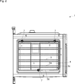
- Figure 1 – is a schematic partial front view of a cooking appliance according to an embodiment of the present invention.
- Figure 2 – is a schematic sectional view of the cooking appliance of Fig. 1, taken along the line A-A;
- Figure 3 – is a schematic perspective enlarged view of a detail of the cooking appliance of Fig. 1;
- Figure 4 – is a schematic perspective exploded view of the side wire rack and a fixing device of the cooking appliance of Fig. 1.
- the cooking appliance (1) comprises: a cavity (2) for cooking food; a pair of side wire racks (3) which are disposed onto the side walls (4) of the cavity (2) respectively, and adapted to support a tray (not shown) at one or more different levels, wherein the side wire racks (3) each comprises one or more wires (5) ; and one or more fixing devices (6) for fixing the side wire racks (3) to the side walls (4) of the cavity (2) (Fig. 1).
- each side wire rack (3) comprises three bending wire sections (7) which are adapted to form-fittingly engage with the fixing devices (6) respectively (Fig. 2 and Fig. 3).
- each side wire rack (3) comprises only three bending wire sections (7) which are adapted to form-fittingly engage with three fixing devices (6) respectively (Fig. 4).
- each fixing device (6) comprises a retaining member (8) which comprises a heat resistant and electrically insulating material, and which is adapted to keep the respective side wire rack (3) at an electrically safe distance from the side wall (4) of the cavity (2) (Fig. 3).
- the retaining member (8) comprises ceramic material.
- each fixing device (6) comprises a groove (9) which is formed into the retaining member (8) and adapted to fit around the respective bending wire section (7) (Fig. 3 and Fig. 4).
- each fixing device (6) comprises: a fastener (10) which is adapted to fasten the retaining member (8) to the respective hole on the side wall (4) ; and a bore (11) which is formed into the retaining member (8) and adapted to receive the fastener (10) (Fig. 3 and Fig. 4).
- the retaining member (8) including the groove (9) and the bore (11) is a single piece (Fig. 4).
- the fastener (10) comprises a threaded bolt (12) (Fig. 4).
- the threaded bolt (12) comprises ceramic material.
- each fixing device (6) comprises a bush (13) which comprises a heat resistant and electrically insulating material and which is adapted to be inserted into the bore (11) of the retaining member (8) and to be fitted around the fastener (10) (Fig. 4).
- the bush (13) comprises ceramic material.
- each fixing device (6) comprises: a rivet (14) which is adapted to be fitted into the respective hole on the side wall (4) ; and a recess (15) which is formed into the rivet (14) and adapted to receive the fastener (10) (Fig. 4).
- the recess (15) of the rivet (14) is adapted to threadably receive the threaded bolt (12) (Fig. 4).
- the cooking appliance (1) further comprises a magnetron (not shown) for generating microwaves inside the cavity (2) .
- each side wire rack (3) comprises: one or more pairs of horizontal wires (5a) which are u-shaped and arranged at different levels, wherein each pair of horizontal wires (5a) is adapted to slidably support and secure the tray; and a frame wire (5b) which is joined to the opposite ends of the pairs of horizontal wires (5a) , wherein the bending wire sections (7) are formed into the frame wire (5b) (Fig. 4).
- each side wire rack (3) further comprises a stopping wire (5c) for blocking the inward movement of the tray (Fig. 4).
- two bending wire sections (7) are formed into the upper part of the frame wire (5b) and adapted to form-fittingly engage with the fixing devices (6) from above respectively; and one bending wire section (7) is formed into the lower part of the frame wire (5b) and adapted to form-fittingly engage with the respective fixing device (6) from below (Fig. 2 and Fig. 4).
- the bending wire sections (7) are semicircular shaped (Fig. 2).
- the grooves (9) are circular shaped (Fig. 4).
- Another major advantageous effect of the present invention is that the side wire racks (3) can be easily manufactured and assembled with the cavity (2).
- the need for the prior art mounting tabs (not shown) has been obviated, and thus the production costs have been decreased both in terms of material and labor.
- Another major advantageous effect of the present invention is that the risk that the side wire racks (3) vibrate or fall out can be eliminated or reduced as much as possible by virtue of the form-fitting engagement between the fixing devices (6) and the side wire racks (3).
- Another major advantageous effect of the present invention is that the side wire racks (3) can be prevented from deformations during the assemblage by virtue of the three-point engagement between side wire racks (3) and the side walls (4). Thereby, the risk that the tray gets stuck in the side wire racks (3) when mounting removing the same can be eliminated or reduced as much as possible.
- Other advantageous effects of the present invention can be taken from the above-described embodiments.
Landscapes
- Engineering & Computer Science (AREA)
- Chemical & Material Sciences (AREA)
- Combustion & Propulsion (AREA)
- Mechanical Engineering (AREA)
- General Engineering & Computer Science (AREA)
- Electric Ovens (AREA)
- Devices For Warming Or Keeping Food Or Tableware Hot (AREA)
Abstract
The present invention relates to a cooking appliance (1) comprising: a cavity (2) for cooking food; a pair of side wire racks (3) which are disposed onto the side walls (4) of the cavity (2) respectively, and adapted to support a tray at one or more different levels, wherein the side wire racks (3) each comprises one or more wires (5); and one or more fixing devices (6) for fixing the side wire racks (3) to the side walls (4) of the cavity (2), wherein each side wire rack (3) comprises three bending wire sections (7) which are adapted to form-fittingly engage with the fixing devices (6) respectively.
Description
The present invention relates to a cooking appliance, in particular to a cooking appliance which has an oven.
Cooking appliances with ovens, in particular with microwave ovens or hybrid ovens with microwave heating functions are commonly known in the art. A cooking appliance generally comprises a cavity for cooking the food; a pair of side wire racks which are disposed onto the side walls of the cavity respectively, and adapted to support a tray at one or more different levels, wherein the side wire racks each comprises one or more wires and mounting tabs welded to the wires; and one or more fixing devices for fixing the mounting tabs to the side walls of the cavity. The user places the food to be cooked onto the tray and mounts it into the cavity by means of the side wire racks.
US 2013/0118471 A1 discloses an oven with a microwave heating function.
A problem with the prior art cooking appliance is that the production of the side wire racks and the assemblage of the side wire racks with the cavity is cost-intensive both in terms of labor and material. Another problem with the prior art cooking appliance is that the side wire racks can easily vibrate during the transportation and fall out. Another problem with the prior art cooking appliance is that the tray can get stuck in the side wire racks when mounting or removing the tray.
An objective of the present invention is to provide a cooking appliance which solves the aforementioned problems of the prior art in a cost-effective way and which enables an improved production and assemblage and an improved usability.
This objective has been achieved by the cooking appliance as defined in claim 1. Further achievements have been attained by the subject-matters respectively defined in the dependent claims.
In the cooking appliance of the present invention each side wire rack comprises three bending wire sections which are adapted to form-fittingly engage with the fixing devices respectively.
A major advantageous effect of the present invention is that the side wire racks can be easily manufactured and assembled with the cavity. In particular, the need for the prior art mounting tabs has been obviated, and thus the production costs have been decreased both in terms of material and labor. Another major advantageous effect of the present invention is that the risk that the side wire racks vibrate or fall out can be eliminated or reduced as much as possible by virtue of the form-fitting engagement between the fixing devices and the side wire racks. Another major advantageous effect of the present invention is that the side wire racks can be prevented from deformations during the assemblage by virtue of the three-point engagement between side wire racks and the side walls. Thereby, the risk that the trays get stuck in the side wire racks when mounting removing the same can be eliminated or reduced as much as possible.
In general, metal objects such as the side wire racks, the trays and the like within the cavity generally pose the risk of spark generation when the microwave heating function is used. Therefore, in an embodiment, each fixing device has a heat resistant and electrically insulating retaining member which keeps the respective side wire rack at an electrically safe distance from the side wall. In another version of this embodiment, the retaining member is manufactured from ceramic. This embodiment is particularly advantageous as the risk of spark generation at the side wire racks within the cavity has been eliminated or reduced as much as possible by virtue of the retaining remember. Thereby, the leakage of the microwave radiation to the outside of the cavity via the side wire racks has been eliminated. Thereby, also the cooking efficiency and the safety of the cooking appliance have been improved.
In another embodiment, the bending wire section is fitted around a groove in the retaining member during the assemblage. In a version of this embodiment, the groove is circular shaped, and the bending wire section is semicircular shaped. This embodiment is particularly advantageous as the side wire racks can be securely kept in place.
In another embodiment, a fastener is inserted into the bore of the retaining member so as to fasten the same to a hole in the side wall. In a version of this embodiment, the fastener is provided as a threaded bold. In another version of this embodiment, the fastener is manufactured from a heat resistant and electrically insulating material. In another version of this embodiment, the fastener is manufactured from ceramic. This embodiment is particularly advantageous as the retaining member can be securely and easily fastened to the side wall.
In another embodiment, the fastener is fitted into a heat resistant and electrically insulating bush that is to be inserted into the bore of the retaining member. In a version of this embodiment, the bush is manufactured from ceramic. This embodiment is particularly advantageous as the fastener can be correctly aligned with the retaining member.
In another embodiment, the fastener is received by the recess in a rivet that is to be fitted into the respective hole on the side wall. In a version of this embodiment, the recess is threaded. This embodiment is particularly advantageous as the fastener can be more securely fastened to the side wall.
In other alternative embodiments, the cooking appliance has a microwave oven or hybrid oven with a microwave heating function.
In another embodiment, each side wire rack is manufactured entirely from wires. In a version of this embodiment, the side wire rack has horizontal wires for slidably supporting the tray, and a frame wire which supports the horizontal wires. In a version of this embodiment, the three bending wire sections are formed into the frame wire. This embodiment is particularly advantageous as the production of the side wire rack is cost-effective both in terms of material and labor.
Additional features and additional advantageous effects of the cooking appliance of the present invention will become more apparent with the detailed description of the embodiments with reference to the accompanying drawings in which:
Figure 1 – is a schematic partial front view of a cooking appliance according to an embodiment of the present invention;
Figure 2 – is a schematic sectional view of the cooking appliance of Fig. 1, taken along the line A-A;
Figure 3 – is a schematic perspective enlarged view of a detail of the cooking appliance of Fig. 1;
Figure 4 – is a schematic perspective exploded view of the side wire rack and a fixing device of the cooking appliance of Fig. 1.
The reference signs appearing on the drawings relate to the following technical features.
- Cooking appliance
- Cavity
- Side wire rack
- Side wall
- Wire
5a. Horizontal wire
5b. Frame wire
5b. Frame wire
5c. Stopping wire
6. Fixing device
7. Bending wire section
8. Retaining member
9. Groove
10. Fastener
11. Bore
12. Threaded bolt
13. Bush
14. Rivet
15. Recess
6. Fixing device
7. Bending wire section
8. Retaining member
9. Groove
10. Fastener
11. Bore
12. Threaded bolt
13. Bush
14. Rivet
15. Recess
The cooking appliance (1) comprises: a cavity (2) for cooking food; a pair of side wire racks (3) which are disposed onto the side walls (4) of the cavity (2) respectively, and adapted to support a tray (not shown) at one or more different levels, wherein the side wire racks (3) each comprises one or more wires (5); and one or more fixing devices (6) for fixing the side wire racks (3) to the side walls (4) of the cavity (2) (Fig. 1).
In the cooking appliance (1) of the present invention, each side wire rack (3) comprises three bending wire sections (7) which are adapted to form-fittingly engage with the fixing devices (6) respectively (Fig. 2 and Fig. 3).
In an embodiment, each side wire rack (3) comprises only three bending wire sections (7) which are adapted to form-fittingly engage with three fixing devices (6) respectively (Fig. 4).
In another embodiment, each fixing device (6) comprises a retaining member (8) which comprises a heat resistant and electrically insulating material, and which is adapted to keep the respective side wire rack (3) at an electrically safe distance from the side wall (4) of the cavity (2) (Fig. 3).
In another embodiment, the retaining member (8) comprises ceramic material.
In another embodiment, each fixing device (6) comprises a groove (9) which is formed into the retaining member (8) and adapted to fit around the respective bending wire section (7) (Fig. 3 and Fig. 4).
In another embodiment, the side walls (4) each comprises three holes (not shown) for the installation of the fixing devices (6) respectively. In this embodiment, each fixing device (6) comprises: a fastener (10) which is adapted to fasten the retaining member (8) to the respective hole on the side wall (4); and a bore (11) which is formed into the retaining member (8) and adapted to receive the fastener (10) (Fig. 3 and Fig. 4).
In another embodiment, the retaining member (8), including the groove (9) and the bore (11) is a single piece (Fig. 4).
In another embodiment, the fastener (10) comprises a threaded bolt (12) (Fig. 4).
In another embodiment, the threaded bolt (12) comprises ceramic material.
In another embodiment, each fixing device (6) comprises a bush (13) which comprises a heat resistant and electrically insulating material and which is adapted to be inserted into the bore (11) of the retaining member (8) and to be fitted around the fastener (10) (Fig. 4).
In another embodiment, the bush (13) comprises ceramic material.
In another embodiment, each fixing device (6) comprises: a rivet (14) which is adapted to be fitted into the respective hole on the side wall (4); and a recess (15) which is formed into the rivet (14) and adapted to receive the fastener (10) (Fig. 4).
In another embodiment, the recess (15) of the rivet (14) is adapted to threadably receive the threaded bolt (12) (Fig. 4).
In another embodiment, the cooking appliance (1) further comprises a magnetron (not shown) for generating microwaves inside the cavity (2).
In another embodiment, each side wire rack (3) comprises: one or more pairs of horizontal wires (5a) which are u-shaped and arranged at different levels, wherein each pair of horizontal wires (5a) is adapted to slidably support and secure the tray; and a frame wire (5b) which is joined to the opposite ends of the pairs of horizontal wires (5a), wherein the bending wire sections (7) are formed into the frame wire (5b) (Fig. 4).
In another embodiment, each side wire rack (3) further comprises a stopping wire (5c) for blocking the inward movement of the tray (Fig. 4).
In another embodiment, two bending wire sections (7) are formed into the upper part of the frame wire (5b) and adapted to form-fittingly engage with the fixing devices (6) from above respectively; and one bending wire section (7) is formed into the lower part of the frame wire (5b) and adapted to form-fittingly engage with the respective fixing device (6) from below (Fig. 2 and Fig. 4).
In another embodiment, the bending wire sections (7) are semicircular shaped (Fig. 2). In this embodiment, the grooves (9) are circular shaped (Fig. 4).
Another major advantageous effect of the present invention is that the side wire racks (3) can be easily manufactured and assembled with the cavity (2). In particular, the need for the prior art mounting tabs (not shown) has been obviated, and thus the production costs have been decreased both in terms of material and labor. Another major advantageous effect of the present invention is that the risk that the side wire racks (3) vibrate or fall out can be eliminated or reduced as much as possible by virtue of the form-fitting engagement between the fixing devices (6) and the side wire racks (3). Another major advantageous effect of the present invention is that the side wire racks (3) can be prevented from deformations during the assemblage by virtue of the three-point engagement between side wire racks (3) and the side walls (4). Thereby, the risk that the tray gets stuck in the side wire racks (3) when mounting removing the same can be eliminated or reduced as much as possible. Other advantageous effects of the present invention can be taken from the above-described embodiments.
Claims (15)
- A cooking appliance (1) comprising: a cavity (2) for cooking food; a pair of side wire racks (3) which are disposed onto the side walls (4) of the cavity (2) respectively, and adapted to support a tray at one or more different levels, wherein the side wire racks (3) each comprises one or more wires (5); and one or more fixing devices (6) for fixing the side wire racks (3) to the side walls (4) of the cavity (2), characterized in that each side wire rack (3) comprises three bending wire sections (7) which are adapted to form-fittingly engage with the fixing devices (6) respectively.
- The cooking appliance (1) according to claim 1, characterized in that each fixing device (6) comprises a retaining member (8) which comprises a heat resistant and electrically insulating material, and which is adapted to keep the respective side wire rack (3) at an electrically safe distance from the side wall (4) of the cavity (2).
- The cooking appliance (1) according to claim 2, characterized in that the retaining member (8) comprises ceramic material.
- The cooking appliance (1) according to claim 2 or 3, characterized in that each fixing device (6) comprises a groove (9) which is formed into the retaining member (8) and adapted to fit around the respective bending wire section (7).
- The cooking appliance (1) according to any one of claims 2 to 4, characterized in that the side walls (4) each comprises three holes for the installation of the fixing devices (6) respectively; and each fixing device (6) comprises: a fastener (10) which is adapted to fasten the retaining member (8) to the respective hole on the side wall (4); and a bore (11) which is formed into the retaining member (8) and adapted to receive the fastener (10).
- The cooking appliance (1) according to claim 5, characterized in that the fastener (10) comprises a threaded bolt (12).
- The cooking appliance (1) according to claim 6, characterized in that the threaded bolt (12) comprises ceramic material.
- The cooking appliance (1) according to any one of claims 5 to 7, characterized in that each fixing device (6) comprises: a bush (13) which comprises a heat resistant and electrically insulating material and which is adapted to be inserted into the bore (11) of the retaining member (8) and to be fitted around the fastener (10).
- The cooking appliance (1) according to claim 8, characterized in that the bush (13) comprises ceramic material.
- The cooking appliance (1) according to any one of claims 5 to 9, characterized in that each fixing device (6) comprises: a rivet (14) which is adapted to be fitted into the respective hole on the side wall (4); and a recess (15) which is formed into the rivet (14) and adapted to receive the fastener (10).
- The cooking appliance (1) according to claim 10, where dependent on claim 6, characterized in that the recess (15) of the rivet (14) is adapted to threadably receive the threaded bolt (12).
- The cooking appliance (1) according to any one of claims 1 to 11, characterized by further comprising a magnetron for generating microwaves inside the cavity (2).
- The cooking appliance (1) according to any one of claims 1 to 12, characterized in that each side wire rack (3) comprises: one or more pairs of horizontal wires (5a) which are u-shaped and arranged at different levels, wherein each pair of horizontal wires (5a) is adapted to slidably support and secure the tray; and a frame wire (5b) which is joined to the opposite ends of the pairs of horizontal wires (5a), wherein the bending wire sections (7) are formed into the frame wire (5b).
- The cooking appliance (1) according to claim 13, characterized in that two bending wire sections (7) are formed into the upper part of the frame wire (5b) and adapted to form-fittingly engage with the fixing devices (6) from above respectively; and one bending wire section (7) is formed into the lower part of the frame wire (5b) and adapted to form-fittingly engage with the respective fixing device (6) from below.
- The cooking appliance (1) according to any one of claims 1 to 13, characterized in that the bending wire sections (7) are semicircular shaped.
Priority Applications (2)
| Application Number | Priority Date | Filing Date | Title |
|---|---|---|---|
| EP17751305.8A EP3494345B1 (en) | 2016-08-03 | 2017-07-26 | Cooking appliance with improved side wire racks |
| PL17751305T PL3494345T3 (en) | 2016-08-03 | 2017-07-26 | Cooking appliance with improved side wire racks |
Applications Claiming Priority (2)
| Application Number | Priority Date | Filing Date | Title |
|---|---|---|---|
| TRA2016/10841 | 2016-08-03 | ||
| TR2016/10841A TR201610841A2 (en) | 2016-08-03 | 2016-08-03 | Cooking appliance with improved side wire racks |
Publications (1)
| Publication Number | Publication Date |
|---|---|
| WO2018024558A1 true WO2018024558A1 (en) | 2018-02-08 |
Family
ID=59581869
Family Applications (1)
| Application Number | Title | Priority Date | Filing Date |
|---|---|---|---|
| PCT/EP2017/068833 Ceased WO2018024558A1 (en) | 2016-08-03 | 2017-07-26 | Cooking appliance with improved side wire racks |
Country Status (4)
| Country | Link |
|---|---|
| EP (1) | EP3494345B1 (en) |
| PL (1) | PL3494345T3 (en) |
| TR (1) | TR201610841A2 (en) |
| WO (1) | WO2018024558A1 (en) |
Cited By (4)
| Publication number | Priority date | Publication date | Assignee | Title |
|---|---|---|---|---|
| US12035845B1 (en) | 2023-04-26 | 2024-07-16 | Sharkninja Operating Llc | Systems and methods for cooking pizza |
| US12372247B2 (en) | 2023-04-26 | 2025-07-29 | Sharkninja Operating Llc | Systems and methods for cooking pizza |
| USD1104596S1 (en) | 2023-05-31 | 2025-12-09 | Sharkninja Operating Llc | Cooking device |
| WO2026027048A1 (en) * | 2024-07-31 | 2026-02-05 | Gorenje, d.o.o. | Holding device for a tray in a cooking compartment of a cooking appliance, cooking appliance and method for attaching a holding device for a tray in a cooking compartment of a cooking appliance |
Families Citing this family (1)
| Publication number | Priority date | Publication date | Assignee | Title |
|---|---|---|---|---|
| DE102023108498A1 (en) * | 2023-04-03 | 2024-10-10 | Rational Aktiengesellschaft | cooking appliance with food carrier frame |
Citations (5)
| Publication number | Priority date | Publication date | Assignee | Title |
|---|---|---|---|---|
| US1013313A (en) * | 1911-07-20 | 1912-01-02 | Ernest Richardson | Oven, refrigerator, and similar receptacle. |
| WO2010076143A2 (en) * | 2008-12-29 | 2010-07-08 | Arcelik Anonim Sirketi | An oven comprising a tray carrying support unit |
| EP2554914A1 (en) * | 2011-08-01 | 2013-02-06 | BSH Bosch und Siemens Hausgeräte GmbH | Side rest for an oven |
| US20130118471A1 (en) | 2011-11-11 | 2013-05-16 | General Electric Company | Extendable rack mounting system for an oven appliance |
| EP2757322A1 (en) * | 2013-01-18 | 2014-07-23 | Electrolux Home Products Corporation N.V. | A side grid system for an oven cavity |
Family Cites Families (1)
| Publication number | Priority date | Publication date | Assignee | Title |
|---|---|---|---|---|
| EP3372054A1 (en) * | 2015-11-06 | 2018-09-12 | Arçelik Anonim Sirketi | Side wire rack fixing device for a cooking appliance with microwave heating function |
-
2016
- 2016-08-03 TR TR2016/10841A patent/TR201610841A2/en unknown
-
2017
- 2017-07-26 EP EP17751305.8A patent/EP3494345B1/en active Active
- 2017-07-26 WO PCT/EP2017/068833 patent/WO2018024558A1/en not_active Ceased
- 2017-07-26 PL PL17751305T patent/PL3494345T3/en unknown
Patent Citations (5)
| Publication number | Priority date | Publication date | Assignee | Title |
|---|---|---|---|---|
| US1013313A (en) * | 1911-07-20 | 1912-01-02 | Ernest Richardson | Oven, refrigerator, and similar receptacle. |
| WO2010076143A2 (en) * | 2008-12-29 | 2010-07-08 | Arcelik Anonim Sirketi | An oven comprising a tray carrying support unit |
| EP2554914A1 (en) * | 2011-08-01 | 2013-02-06 | BSH Bosch und Siemens Hausgeräte GmbH | Side rest for an oven |
| US20130118471A1 (en) | 2011-11-11 | 2013-05-16 | General Electric Company | Extendable rack mounting system for an oven appliance |
| EP2757322A1 (en) * | 2013-01-18 | 2014-07-23 | Electrolux Home Products Corporation N.V. | A side grid system for an oven cavity |
Cited By (5)
| Publication number | Priority date | Publication date | Assignee | Title |
|---|---|---|---|---|
| US12035845B1 (en) | 2023-04-26 | 2024-07-16 | Sharkninja Operating Llc | Systems and methods for cooking pizza |
| US12372247B2 (en) | 2023-04-26 | 2025-07-29 | Sharkninja Operating Llc | Systems and methods for cooking pizza |
| US12408792B2 (en) | 2023-04-26 | 2025-09-09 | Sharkninja Operating Llc | Systems and methods for cooking pizza |
| USD1104596S1 (en) | 2023-05-31 | 2025-12-09 | Sharkninja Operating Llc | Cooking device |
| WO2026027048A1 (en) * | 2024-07-31 | 2026-02-05 | Gorenje, d.o.o. | Holding device for a tray in a cooking compartment of a cooking appliance, cooking appliance and method for attaching a holding device for a tray in a cooking compartment of a cooking appliance |
Also Published As
| Publication number | Publication date |
|---|---|
| EP3494345A1 (en) | 2019-06-12 |
| EP3494345B1 (en) | 2020-12-02 |
| TR201610841A2 (en) | 2018-02-21 |
| PL3494345T3 (en) | 2021-06-14 |
Similar Documents
| Publication | Publication Date | Title |
|---|---|---|
| EP3494345B1 (en) | Cooking appliance with improved side wire racks | |
| US10288296B2 (en) | Cooking appliance | |
| US9072403B2 (en) | Home appliance with improved griddle insulation retainer | |
| US20120160228A1 (en) | Cooking appliance | |
| EP2757322B1 (en) | A side grid system for an oven cavity | |
| US8826898B2 (en) | Metal rack for an oven appliance | |
| US20230383959A1 (en) | Cooking chamber insert with handle zones between an exposed heating body and an edge, and cooking device | |
| US20130118475A1 (en) | Metal rack for an oven appliance | |
| KR100208871B1 (en) | Cooking apparatus, eg ovens with protectors for heating elements | |
| US10616961B2 (en) | Side wire rack fixing device for a cooking appliance with microwave heating function | |
| US20160327276A1 (en) | Cooking appliance | |
| EP2390585B1 (en) | An oven cavity for a cooking oven | |
| KR101238105B1 (en) | Electric oven | |
| WO2018188722A1 (en) | Cooking appliance with improved assemblage | |
| US20110147361A1 (en) | Household appliance | |
| KR101620100B1 (en) | A Aooker | |
| KR19990032462A (en) | Suspension Microwave Support Device | |
| JP2011220590A (en) | Cooker | |
| KR100771629B1 (en) | Electric range | |
| KR100850019B1 (en) | A Mounting Structure Of Rack Shelf for Microwave Oven | |
| KR101756990B1 (en) | Heater unit and cooking appliance comprising the same | |
| US20240392829A1 (en) | Systems for hinge receivers in cooking appliances | |
| WO2017190796A1 (en) | Cooking appliance with a microwave heating function | |
| EP3798519A1 (en) | A cooking device | |
| EP2798275B1 (en) | A cooker |
Legal Events
| Date | Code | Title | Description |
|---|---|---|---|
| 121 | Ep: the epo has been informed by wipo that ep was designated in this application |
Ref document number: 17751305 Country of ref document: EP Kind code of ref document: A1 |
|
| NENP | Non-entry into the national phase |
Ref country code: DE |
|
| ENP | Entry into the national phase |
Ref document number: 2017751305 Country of ref document: EP Effective date: 20190304 |