WO2018025329A1 - Système de surveillance de collecteur de courant - Google Patents
Système de surveillance de collecteur de courant Download PDFInfo
- Publication number
- WO2018025329A1 WO2018025329A1 PCT/JP2016/072668 JP2016072668W WO2018025329A1 WO 2018025329 A1 WO2018025329 A1 WO 2018025329A1 JP 2016072668 W JP2016072668 W JP 2016072668W WO 2018025329 A1 WO2018025329 A1 WO 2018025329A1
- Authority
- WO
- WIPO (PCT)
- Prior art keywords
- current collector
- current
- monitoring system
- state
- event
- Prior art date
- Legal status (The legal status is an assumption and is not a legal conclusion. Google has not performed a legal analysis and makes no representation as to the accuracy of the status listed.)
- Ceased
Links
Images

Classifications
-
- B—PERFORMING OPERATIONS; TRANSPORTING
- B60—VEHICLES IN GENERAL
- B60L—PROPULSION OF ELECTRICALLY-PROPELLED VEHICLES; SUPPLYING ELECTRIC POWER FOR AUXILIARY EQUIPMENT OF ELECTRICALLY-PROPELLED VEHICLES; ELECTRODYNAMIC BRAKE SYSTEMS FOR VEHICLES IN GENERAL; MAGNETIC SUSPENSION OR LEVITATION FOR VEHICLES; MONITORING OPERATING VARIABLES OF ELECTRICALLY-PROPELLED VEHICLES; ELECTRIC SAFETY DEVICES FOR ELECTRICALLY-PROPELLED VEHICLES
- B60L3/00—Electric devices on electrically-propelled vehicles for safety purposes; Monitoring operating variables, e.g. speed, deceleration or energy consumption
- B60L3/12—Recording operating variables ; Monitoring of operating variables
-
- B—PERFORMING OPERATIONS; TRANSPORTING
- B60—VEHICLES IN GENERAL
- B60L—PROPULSION OF ELECTRICALLY-PROPELLED VEHICLES; SUPPLYING ELECTRIC POWER FOR AUXILIARY EQUIPMENT OF ELECTRICALLY-PROPELLED VEHICLES; ELECTRODYNAMIC BRAKE SYSTEMS FOR VEHICLES IN GENERAL; MAGNETIC SUSPENSION OR LEVITATION FOR VEHICLES; MONITORING OPERATING VARIABLES OF ELECTRICALLY-PROPELLED VEHICLES; ELECTRIC SAFETY DEVICES FOR ELECTRICALLY-PROPELLED VEHICLES
- B60L13/00—Electric propulsion for monorail vehicles, suspension vehicles or rack railways; Magnetic suspension or levitation for vehicles
- B60L13/006—Electric propulsion adapted for monorail vehicles, suspension vehicles or rack railways
-
- B—PERFORMING OPERATIONS; TRANSPORTING
- B60—VEHICLES IN GENERAL
- B60L—PROPULSION OF ELECTRICALLY-PROPELLED VEHICLES; SUPPLYING ELECTRIC POWER FOR AUXILIARY EQUIPMENT OF ELECTRICALLY-PROPELLED VEHICLES; ELECTRODYNAMIC BRAKE SYSTEMS FOR VEHICLES IN GENERAL; MAGNETIC SUSPENSION OR LEVITATION FOR VEHICLES; MONITORING OPERATING VARIABLES OF ELECTRICALLY-PROPELLED VEHICLES; ELECTRIC SAFETY DEVICES FOR ELECTRICALLY-PROPELLED VEHICLES
- B60L15/00—Methods, circuits, or devices for controlling the traction-motor speed of electrically-propelled vehicles
- B60L15/002—Methods, circuits, or devices for controlling the traction-motor speed of electrically-propelled vehicles for control of propulsion for monorail vehicles, suspension vehicles or rack railways; for control of magnetic suspension or levitation for vehicles for propulsion purposes
-
- B—PERFORMING OPERATIONS; TRANSPORTING
- B60—VEHICLES IN GENERAL
- B60L—PROPULSION OF ELECTRICALLY-PROPELLED VEHICLES; SUPPLYING ELECTRIC POWER FOR AUXILIARY EQUIPMENT OF ELECTRICALLY-PROPELLED VEHICLES; ELECTRODYNAMIC BRAKE SYSTEMS FOR VEHICLES IN GENERAL; MAGNETIC SUSPENSION OR LEVITATION FOR VEHICLES; MONITORING OPERATING VARIABLES OF ELECTRICALLY-PROPELLED VEHICLES; ELECTRIC SAFETY DEVICES FOR ELECTRICALLY-PROPELLED VEHICLES
- B60L5/00—Current collectors for power supply lines of electrically-propelled vehicles
- B60L5/18—Current collectors for power supply lines of electrically-propelled vehicles using bow-type collectors in contact with trolley wire
-
- G—PHYSICS
- G01—MEASURING; TESTING
- G01H—MEASUREMENT OF MECHANICAL VIBRATIONS OR ULTRASONIC, SONIC OR INFRASONIC WAVES
- G01H1/00—Measuring characteristics of vibrations in solids by using direct conduction to the detector
-
- G—PHYSICS
- G06—COMPUTING OR CALCULATING; COUNTING
- G06T—IMAGE DATA PROCESSING OR GENERATION, IN GENERAL
- G06T7/00—Image analysis
- G06T7/0002—Inspection of images, e.g. flaw detection
-
- G—PHYSICS
- G06—COMPUTING OR CALCULATING; COUNTING
- G06T—IMAGE DATA PROCESSING OR GENERATION, IN GENERAL
- G06T7/00—Image analysis
- G06T7/0002—Inspection of images, e.g. flaw detection
- G06T7/0004—Industrial image inspection
-
- B—PERFORMING OPERATIONS; TRANSPORTING
- B60—VEHICLES IN GENERAL
- B60L—PROPULSION OF ELECTRICALLY-PROPELLED VEHICLES; SUPPLYING ELECTRIC POWER FOR AUXILIARY EQUIPMENT OF ELECTRICALLY-PROPELLED VEHICLES; ELECTRODYNAMIC BRAKE SYSTEMS FOR VEHICLES IN GENERAL; MAGNETIC SUSPENSION OR LEVITATION FOR VEHICLES; MONITORING OPERATING VARIABLES OF ELECTRICALLY-PROPELLED VEHICLES; ELECTRIC SAFETY DEVICES FOR ELECTRICALLY-PROPELLED VEHICLES
- B60L2200/00—Type of vehicles
- B60L2200/30—Trolleys
-
- G—PHYSICS
- G01—MEASURING; TESTING
- G01R—MEASURING ELECTRIC VARIABLES; MEASURING MAGNETIC VARIABLES
- G01R31/00—Arrangements for testing electric properties; Arrangements for locating electric faults; Arrangements for electrical testing characterised by what is being tested not provided for elsewhere
- G01R31/005—Testing of electric installations on transport means
- G01R31/008—Testing of electric installations on transport means on air- or spacecraft, railway rolling stock or sea-going vessels
-
- G—PHYSICS
- G06—COMPUTING OR CALCULATING; COUNTING
- G06T—IMAGE DATA PROCESSING OR GENERATION, IN GENERAL
- G06T2207/00—Indexing scheme for image analysis or image enhancement
- G06T2207/30—Subject of image; Context of image processing
- G06T2207/30248—Vehicle exterior or interior
- G06T2207/30252—Vehicle exterior; Vicinity of vehicle
-
- Y—GENERAL TAGGING OF NEW TECHNOLOGICAL DEVELOPMENTS; GENERAL TAGGING OF CROSS-SECTIONAL TECHNOLOGIES SPANNING OVER SEVERAL SECTIONS OF THE IPC; TECHNICAL SUBJECTS COVERED BY FORMER USPC CROSS-REFERENCE ART COLLECTIONS [XRACs] AND DIGESTS
- Y02—TECHNOLOGIES OR APPLICATIONS FOR MITIGATION OR ADAPTATION AGAINST CLIMATE CHANGE
- Y02T—CLIMATE CHANGE MITIGATION TECHNOLOGIES RELATED TO TRANSPORTATION
- Y02T10/00—Road transport of goods or passengers
- Y02T10/60—Other road transportation technologies with climate change mitigation effect
- Y02T10/64—Electric machine technologies in electromobility
Definitions
- This disclosure relates to a current collector monitoring system.
- the current collector has a structure in which the current collector boat is supported by a current collecting arm.
- the current collector boat includes a boat body and a sliding plate attached to the upper surface of the boat body, and is configured to press the sliding plate against the lower edge of the overhead wire and take in electricity from the overhead wire to the train (Patent Document 1). reference).
- Various abnormalities may occur in the current collector.
- Various abnormalities include, for example, that a bird collides with a current collecting boat, the current collecting boat is deformed, and a foreign object adheres to the current collecting boat. It is desirable that one aspect of the present disclosure can provide a current collector monitoring system that enables early detection of an abnormality related to a current collector.
- a current collecting current measurement unit configured to measure a current collected by a current collector and a state of the current collector are preset.
- a current collecting current state determining unit configured to determine whether or not an abnormal state is satisfied; and a current collecting boat included in the current collecting device when the current collecting current state corresponds to the abnormal state.
- An image acquisition unit configured to acquire an image included in an angle of view; an event recognition unit configured to recognize an event related to the current collector boat in the image; and the event is preset
- An event determination unit configured to determine whether or not the event corresponds to an abnormal event, and a determination result output unit configured to output a signal including a determination result of the event determination unit.
- This current collector monitoring system enables early detection of abnormality related to the current collector.
- the current collector monitoring system acquires an image when the state of the current collection corresponds to an abnormal state. Therefore, it is possible to reduce the burden of processing executed by the current collector monitoring system, as compared with a method of constantly acquiring images.
- a current collector monitoring system corresponds to a vibration measurement unit configured to measure vibration of a current collecting boat included in the current collector, and an abnormal state in which the state of the vibration is set in advance.
- a vibration state determination unit configured to determine whether or not to perform, and when the vibration state corresponds to the abnormal state, the vibration state determination unit is configured to acquire an image including the current collecting boat within an angle of view.
- An event determination unit configured, and a determination result output unit configured to output a signal including a determination result of the event determination unit.
- This current collector monitoring system enables early detection of abnormality related to the current collector.
- the current collector monitoring system acquires an image when the state of vibration in the current collector boat corresponds to an abnormal state. Therefore, it is possible to reduce the burden of processing executed by the current collector monitoring system, as compared with a method of constantly acquiring images.
- vibration measurement unit 55 ... vibration state determination unit, 57 ... image acquisition unit, 59 ... event recognition unit, 61 ... event determination unit, 63 ... determination result output unit, 65 ... vehicle control unit, 67 ... System Result output unit, 69 ... vehicle information acquisition unit
- FIGS. 1 Configuration of Current Collector Monitoring System 1
- the configuration of a current collector monitoring system (hereinafter simply referred to as “monitoring system”) 1 will be described with reference to FIGS.
- the monitoring system 1 is mounted on the railway vehicle 10.
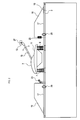
- the railway vehicle 10 includes a plurality of current collectors 3 shown in FIG. In FIG. 2, for simplification of illustration, one of the plurality of current collectors 3 is illustrated.
- the monitoring system 1 is provided for each current collector 3.
- the current collector 3 monitored by the monitoring system 1 may be referred to as the current collector 3 corresponding to the monitoring system 1.
- the current collector 3 is installed on the roof 5 of the railway vehicle 10.
- the current collector 3 includes insulators 7 and 9, a base 11, a current collecting boat 13, and a current collecting arm 15.
- the insulators 7 and 9 fix the base 11 on the roof 5.
- the current collecting arm 15 supports the current collecting boat 13 by extending obliquely upward from one side of the base 11 in the front-rear direction (traveling direction of the railway vehicle 10) to the other side.
- the current collecting arm 15 can swing in the direction of the arrow shown in FIG. 2, and is biased in a direction to push up the current collecting boat 13 by a spring (not shown).
- the current collector boat 13 comes into contact with an overhead line (not shown) and takes electricity into the railway vehicle 10 from this overhead line.
- the electricity taken into the current collector boat 13 is sent to the power distribution cable 17 through a cable (not shown) passing through the current collector 3.
- a windshield 19 for reducing wind noise generated by the current collector 3 is provided on the roof 5.
- the monitoring system 1 includes a control device 21, a first camera 23, a second camera 25, an acceleration sensor 27, a first clamp meter 29, a second clamp meter 31, a vehicle speed sensor 33, A GPS 35, an output current sensor 37, a cab monitor 39, a communication device 41, a vehicle control unit 45, and a storage unit 47 are provided.
- the control device 21 is a known computer including a CPU, RAM, ROM, and the like.
- the control device 21 executes processing to be described later with a program stored in the ROM.
- the control device 21 functionally includes a collected current measurement unit 49, a collected current state determination unit 51, a vibration measurement unit 53, a vibration state determination unit 55, an image acquisition unit 57, an event recognition unit 59, an event determination unit 61, A determination result output unit 63, a vehicle control unit 65, a control result output unit 67, and a vehicle information acquisition unit 69 are provided. The function of each unit will be described later.
- the first camera 23 is installed on the roof 5 as shown in FIG.
- the current collecting boat 13 is included in the angle of view of the first camera 23.
- the first camera 23 has a sensitivity wavelength that is preferable for recognizing the current collecting boat 13 in the captured image.
- the second camera 25 is installed on the roof 5 as shown in FIG.
- the current collecting boat 13 is included in the angle of view of the second camera 25.
- the second camera 25 has a sensitivity wavelength preferable for recognizing arc light generated between the current collecting boat 13 and the overhead line in the photographed image.
- the acceleration sensor 27 is installed in the current collector boat 13 as shown in FIG.
- the acceleration sensor 27 can measure the acceleration of the current collecting boat 13 in the vertical direction, the front-rear direction, and the width direction (direction orthogonal to the paper surface in FIG. 2).
- the first clamp meter 29 measures the value of the collected current (hereinafter referred to as the corresponding collected current) in the power distribution cable 17 connected to the current collector 3 corresponding to the monitoring system 1. To do.
- the second clamp meter 31 measures the value of the collected current (hereinafter referred to as the adjacent collected current) in the power distribution cable 17 connected to the current collector 3 adjacent to the current collector 3 corresponding to the monitoring system 1. To do.
- the vehicle speed sensor 33 measures the speed of the railway vehicle 10.
- the GPS 35 acquires the position of the railway vehicle 10.
- the output current sensor 37 measures the output current value of the railway vehicle 10 (current value of the driving current of the railway vehicle 10).
- the cab monitor 39 is a monitor provided on a cab (not shown) of the railway vehicle 10 and capable of displaying images.
- the communication device 41 is a device that can perform wireless communication with a command center 43 that exists outside the railway vehicle 10.
- the vehicle control unit 45 controls the speed and the like of the railway vehicle 10.
- the storage unit 47 includes a hard disk drive and the like, and can store various information.
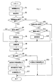
- step 1 of FIG. 3 the collected current measuring unit 49 uses the first clamp meter 29 to measure the value of the corresponding collected current continuously for a predetermined time.
- the collected current measuring unit 49 uses the second clamp meter 31 to measure the value of the adjacent collected current continuously for a predetermined time. The measurement result is stored in the storage unit 47.
- step 2 the vibration measurement unit 53 uses the acceleration sensor 27 to continuously measure the acceleration of the current collecting boat 13 for a predetermined time. As a result, data in which the acceleration of the current collecting boat 13 changes in time series is obtained. This data is data representing the vibration of the current collecting boat 13.
- the vehicle speed sensor 33 is used to measure the speed of the railway vehicle 10. Data in which the acceleration of the current collecting boat 13 changes in time series and the speed of the railway vehicle 10 are stored in the storage unit 47 in association with each other.
- step 3 the collected current state determination unit 51 determines whether or not the collected current state measured in step 1 corresponds to a preset abnormal state.
- the abnormal states include the following states (a1) to (a3).
- ⁇ State (a1) State in which the magnitude of the corresponding collected current is outside the preset normal range.
- the normal range may be a range having an upper limit value and a lower limit value, a range having only an upper limit value, or a range having only a lower limit value.
- ⁇ State (a2) State where the occurrence frequency of the no-current state is equal to or greater than the threshold in the measurement result of the corresponding collected current.
- the no-current state means a state where the value of the corresponding collected current is 0 or a value close thereto.
- the occurrence frequency means the number of occurrences of no-current state per unit time.
- State (a3) A state in which the difference in the current value between the corresponding current collection current and the adjacent current collection current (the deviation in the current collection current between the current collectors) is equal to or greater than the threshold value. If the collected current state corresponds to any one of the states (a1) to (a3), the process proceeds to step 4;
- the collected current state determination unit 51 determines whether or not the degree of the abnormal state is significant. For example, when the current collection current is in the state (a1), if the difference between the magnitude of the corresponding current collection current and the upper limit value or the lower limit value of the normal range exceeds a predetermined value, the degree of abnormal state is significant. In other cases, it is determined that the degree of abnormal state is not significant.
- the degree of the abnormal state is remarkable. In other cases, it is determined that the degree of the abnormal state is not remarkable.
- step 5 the determination result output unit 63 outputs an abnormal signal to the cab monitor 39 and transmits the abnormal signal to the command station 43 using the communication device 41.
- the cab monitor 39 displays a warning image according to the abnormality signal.
- step 6 the image acquisition unit 57 acquires an image using the first camera 23 and the second camera 25.
- the acquired image is stored in the storage unit 47.
- step 7 the event recognition unit 59 recognizes an event related to the current collector boat 13 in the image acquired in step 6.
- Events related to the current collecting boat 13 include the shape of the current collecting boat 13, adhesion of foreign matter to the current collecting boat 13, operation of the current collecting boat 13 (for example, the period of vertical movement, amplitude of vertical movement, etc.), And the arc light generated between the current collecting boat 13 and the overhead wire.
- the shape of the current collecting boat 13, the attachment of foreign matter to the current collecting boat 13, the operation of the current collecting boat 13, and the inclination of the current collecting boat can be recognized in an image acquired using the first camera 23. Further, the arc light generated between the current collecting boat 13 and the overhead wire can be recognized in an image acquired using the second camera 25.
- the event determination unit 61 determines whether or not the event related to the current collector boat 13 recognized in step 7 corresponds to a preset abnormal event.
- the abnormal events include the following events (e1) to (e6).
- Event (e1) The difference (the degree of deformation of the current collecting boat 13) between the shape of the current collecting boat 13 recognized in the image acquired in step 6 and the original shape of the current collecting boat 13 is a predetermined value. Above the threshold.
- Event (e2) A foreign object is attached to the current collecting boat 13, and the size of the foreign object is greater than or equal to a predetermined threshold value.
- Event (e3) The mode of operation of the current collecting boat 13 deviates from the preset normal range. For example, the amplitude and period in the vertical movement of the current collecting boat 13 are out of the normal range.
- Event (e4) The inclination of the current collector boat 13 is equal to or greater than the threshold value.
- Event (e5) The occurrence frequency of arc light is equal to or greater than a threshold value.
- Event (e6) The duration of one arc of light is greater than or equal to the threshold value.
- step 9 the determination result output unit 63 outputs a signal including a determination result that the event related to the current collector boat 13 is an abnormal event (hereinafter referred to as an abnormal event signal) to the cab monitor 39 and the communication device. 41 is transmitted to the command station 43.
- the cab monitor 39 displays an image notifying that an abnormal event has occurred in response to the abnormal event signal.
- the judgment result output unit 63 outputs the vehicle information together with the abnormal event signal to the cab monitor 39 and transmits it to the command station 43.
- the vehicle information is information including the speed of the railway vehicle 10, the position of the railway vehicle 10, and the output current value of the railway vehicle 10.
- the cab monitor 39 displays vehicle information.
- the vehicle information acquisition unit 69 acquires the speed of the railway vehicle 10 using the vehicle speed sensor 33. Further, the position of the railway vehicle 10 is acquired by the vehicle information acquisition unit 69 using the GPS 35. Further, the output current value of the railway vehicle 10 is acquired by the vehicle information acquisition unit 69 using the output current sensor 37.
- the determination result output unit 63 outputs the image acquired in step 6 together with the abnormal event signal and the vehicle information to the cab monitor 39 and transmits it to the command station 43.
- the cab monitor 39 displays the image.
- step 10 the vehicle control unit 65 performs control to reduce the speed of the railway vehicle 10 using the vehicle control unit 45.
- the control for reducing the speed may be control (notch down or notch off) for reducing the driving current of the railway vehicle 10, or may be control for applying a brake.
- step 11 the control result output unit 67 outputs a signal peculiar to the case where the processing of step 10 is performed to the cab monitor 39 and transmits it to the command station 43.
- step 12 the determination result output unit 63 outputs a signal including a determination result that the event related to the current collector boat 13 is not an abnormal event to the cab monitor 39, It transmits to the command center 43.
- step 3 the vibration state determination unit 55 determines whether or not the vibration state of the current collecting boat 13 that appears in the data acquired in step 2 corresponds to a preset abnormal state.
- the abnormal states include the following states (b1) and (b2).
- State (b1) State in which the amplitude of vibration is greater than or equal to the threshold value.
- the first speed and the second speed can be set in advance. Further, the first speed and the second speed can be sections having a certain width with respect to the speed.
- the ratio R is calculated as follows. If the data acquired in the previous step 2 is data acquired at the first speed, the data acquired at the second speed in the past is read from the storage unit 47. Then, the ratio R is calculated from the data acquired in the previous step 2 and the data read from the storage unit 47.
- the data acquired in the previous step 2 is the data acquired at the second speed
- the data acquired in the past at the first speed is read from the storage unit 47.
- the ratio R is calculated from the data acquired in the previous step 2 and the data read from the storage unit 47.
- step 14 the vibration state determination unit 55 determines whether or not the degree of the abnormal state is significant.
- the state (b1) is an abnormal state
- the difference between the amplitude of vibration and the threshold value exceeds a predetermined value, it is determined that the degree of the abnormal state is significant, and otherwise, the abnormal state It is judged that the degree of is not remarkable.
- step 15 the determination result output unit 63 outputs an abnormality signal to the cab monitor 39 and transmits the abnormality signal to the command station 43 using the communication device 41.
- the cab monitor 39 displays a warning image according to the abnormality signal.
- the monitoring system 1 acquires an image including the current collecting boat 13 within the angle of view, recognizes an event related to the current collecting boat 13 in the image, and the recognized event is abnormal. Judge whether it falls under an event. Furthermore, the monitoring system 1 outputs a signal including the determination result. As a result, the crew of the railway vehicle 10 and the staff of the command station 43 can detect an abnormality related to the current collector boat 13 at an early stage.
- the monitoring system 1 acquires an image on the condition that the current collecting current state corresponds to the abnormal state or the vibration state in the current collecting boat corresponds to the abnormal state. Therefore, it is possible to reduce the burden of processing executed by the monitoring system 1 as compared with a method of constantly acquiring images.
- the monitoring system 1 sets states (a1) to (a3) as abnormal states relating to the state of the collected current. As a result, it is possible to more correctly determine whether or not the state of the collected current corresponds to an abnormal state.
- the monitoring system 1 sets states (b1) and (b2) as abnormal states related to the state of vibration in the current collecting boat 13. This makes it possible to more correctly determine whether or not the vibration state corresponds to an abnormal state.
- the monitoring system 1 includes the shape of the current collector boat 13, the adhesion of foreign matter to the current collector boat 13, the operation of the current collector boat 13, the inclination of the current collector boat 13, And arc light generated between the current collecting boat 13 and the overhead wire is recognized. This makes it possible to detect a wide range of abnormalities related to the current collector boat 13.
- the monitoring system 1 reduces the speed of the railway vehicle 10 when an event related to the current collector boat 13 corresponds to an abnormal event. As a result, the safety of the railway vehicle 10 is improved.
- the monitoring system 1 outputs the image data to the cab monitor 39 and transmits it to the command station 43.
- the crew of the railway vehicle 10 and the staff of the command station 43 can easily understand the situation of the current collector 3.
- the monitoring system 1 outputs vehicle information to the cab monitor 39 and transmits it to the command station 43.
- the crew of the railway vehicle 10 and the staff of the command station 43 can easily understand the situation of the railway vehicle 10.
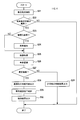
- the monitoring system 1 (especially the control apparatus 21) of this embodiment repeatedly performs the process shown in FIG. 4 with a predetermined period.
- the collected current measuring unit 49 uses the first clamp meter 29 to measure the value of the corresponding collected current continuously for a predetermined time.
- the collected current measuring unit 49 uses the second clamp meter 31 to measure the value of the adjacent collected current continuously for a predetermined time.
- the measurement result is stored in the storage unit 47.
- step 22 the collected current state determination unit 51 determines whether or not the collected current state measured in step 21 corresponds to a preset abnormal state.
- the determination method is the same as in the first embodiment. If the collected current state corresponds to an abnormal state, the process proceeds to step 23, and if not, the process ends.
- step 23 the collected current state determination unit 51 determines whether or not the degree of the abnormal state is remarkable.
- the determination method is the same as in the first embodiment. If the abnormal state is significant, the process proceeds to step 24, and if the abnormal state is not significant, the process proceeds to step 25.
- step 24 the determination result output unit 63 outputs an abnormality signal to the cab monitor 39 and transmits an abnormality signal to the command station 43 using the communication device 41.
- the cab monitor 39 displays a warning image according to the abnormality signal.
- the processing in steps 25 to 31 is the same as the processing in steps 6 to 12 in the first embodiment. According to the second embodiment described in detail above, the following effect (2A) is obtained in addition to the effects (1A), (1C), (1E) to (1I) of the first embodiment described above.
- the monitoring system 1 acquires an image on the condition that the state of the collected current corresponds to an abnormal state. Therefore, it is possible to reduce the burden of processing executed by the monitoring system 1 as compared with a method of constantly acquiring images.
- the basic configuration of the third embodiment is the same as that of the first embodiment, the description of the common configuration will be omitted, and differences will be mainly described.
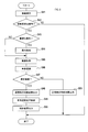
- the monitoring system 1 (especially the control apparatus 21) of this embodiment repeatedly performs the process shown in FIG. 5 with a predetermined period.
- the vibration measurement unit 53 uses the acceleration sensor 27 to continuously measure the acceleration of the current collector boat 13 for a predetermined time. As a result, data in which the acceleration of the current collecting boat 13 changes in time series is obtained. This data is data representing the vibration of the current collecting boat 13.
- the speed of the railway vehicle 10 is also measured using the vehicle speed sensor 33. Data in which the acceleration of the current collecting boat 13 changes in time series and the speed of the railway vehicle 10 are stored in the storage unit 47.
- step 42 the vibration state determination unit 55 determines whether or not the vibration state of the current collecting boat 13 appearing in the data acquired in step 41 corresponds to a preset abnormal state.
- the determination method is the same as in the first embodiment.
- step 43 the vibration state determination unit 55 determines whether or not the degree of the abnormal state is significant. The determination method is the same as in the first embodiment. If the abnormal state is significant, the process proceeds to step 44. If the abnormal state is not significant, the process proceeds to step 45.
- step 44 the determination result output unit 63 outputs an abnormal signal to the cab monitor 39 and transmits the abnormal signal to the command station 43 using the communication device 41.
- the cab monitor 39 displays a warning image according to the abnormality signal.
- the processing in steps 45 to 51 is the same as the processing in steps 6 to 12 in the first embodiment. According to the third embodiment described in detail above, the following effect (3A) is obtained in addition to the effects (1A) and (1D) to (1I) of the first embodiment described above.
- the monitoring system 1 acquires an image on the condition that the state of vibration in the current collecting boat 13 corresponds to an abnormal state. Therefore, it is possible to reduce the burden of processing executed by the monitoring system 1 as compared with a method of constantly acquiring images.
- this indication can take various forms, without being limited to the above-mentioned exemplary embodiment.
- Modified example (1) The abnormal state related to the collected current is not limited to the above-described one, and can be set as appropriate. Moreover, the abnormal state regarding the vibration of the current collecting boat 13 is not limited to the above-mentioned thing, and can be set suitably.
- Modification (2) The events related to the current collecting boat 13 recognized in the image are not limited to those described above, and can be set as appropriate.
- One monitoring system 1 may monitor a plurality of current collectors 3.
Landscapes
- Engineering & Computer Science (AREA)
- Power Engineering (AREA)
- Transportation (AREA)
- Mechanical Engineering (AREA)
- Physics & Mathematics (AREA)
- General Physics & Mathematics (AREA)
- Computer Vision & Pattern Recognition (AREA)
- Quality & Reliability (AREA)
- Theoretical Computer Science (AREA)
- Life Sciences & Earth Sciences (AREA)
- Sustainable Development (AREA)
- Sustainable Energy (AREA)
- Electromagnetism (AREA)
- Current-Collector Devices For Electrically Propelled Vehicles (AREA)
- Electric Propulsion And Braking For Vehicles (AREA)
Abstract
La présente invention concerne un système de surveillance de collecteur de courant comportant, selon un aspect : une unité de mesure de courant collecté ; une unité de détermination d'état de courant collecté ; une unité d'acquisition d'image ; une unité de reconnaissance d'événement ; une unité de détermination d'événement ; et une unité de sortie de résultat de détermination. Lorsque l'état du courant collecté correspond à un état anormal, l'unité d'acquisition d'image acquiert une image comprenant, dans un angle de vue, un sabot collecteur disposé sur un collecteur de courant.
Priority Applications (2)
| Application Number | Priority Date | Filing Date | Title |
|---|---|---|---|
| US16/322,294 US11097619B2 (en) | 2016-08-02 | 2016-08-02 | Current collector monitoring system |
| PCT/JP2016/072668 WO2018025329A1 (fr) | 2016-08-02 | 2016-08-02 | Système de surveillance de collecteur de courant |
Applications Claiming Priority (1)
| Application Number | Priority Date | Filing Date | Title |
|---|---|---|---|
| PCT/JP2016/072668 WO2018025329A1 (fr) | 2016-08-02 | 2016-08-02 | Système de surveillance de collecteur de courant |
Publications (1)
| Publication Number | Publication Date |
|---|---|
| WO2018025329A1 true WO2018025329A1 (fr) | 2018-02-08 |
Family
ID=61072662
Family Applications (1)
| Application Number | Title | Priority Date | Filing Date |
|---|---|---|---|
| PCT/JP2016/072668 Ceased WO2018025329A1 (fr) | 2016-08-02 | 2016-08-02 | Système de surveillance de collecteur de courant |
Country Status (2)
| Country | Link |
|---|---|
| US (1) | US11097619B2 (fr) |
| WO (1) | WO2018025329A1 (fr) |
Cited By (2)
| Publication number | Priority date | Publication date | Assignee | Title |
|---|---|---|---|---|
| US20200369155A1 (en) * | 2017-12-12 | 2020-11-26 | Railway Metrics And Dynamics Sweden Ab | Detection of maintenance status for a pantograph and/or a contact wire |
| EP3847562A4 (fr) * | 2018-09-10 | 2022-06-15 | Pishro Ebtekar Danesh Co. | Système et procédé de surveillance de défaillances de pantographes |
Families Citing this family (3)
| Publication number | Priority date | Publication date | Assignee | Title |
|---|---|---|---|---|
| CN113619646A (zh) * | 2020-06-29 | 2021-11-09 | 株洲中车时代电气股份有限公司 | 一种列车安全出库的控制方法、装置及系统 |
| DE102023204620A1 (de) | 2023-05-17 | 2024-11-21 | Robert Bosch Gesellschaft mit beschränkter Haftung | Verfahren zum Ermitteln einer Zustandsinformation bezüglich eines Zustands eines Stromabnehmers eines Schienenfahrzeugs und/oder einer elektrisch mit dem Schienenfahrzeug verbundenen Oberleitung |
| CN118779630B (zh) * | 2024-06-02 | 2025-05-23 | 苏州智好维科技有限公司 | 一种列车电流曲线特征提取及故障诊断方法 |
Citations (7)
| Publication number | Priority date | Publication date | Assignee | Title |
|---|---|---|---|---|
| JPS63182507A (ja) * | 1987-01-26 | 1988-07-27 | Railway Technical Res Inst | 電気車のパンタグラフ監視装置 |
| JPH05161203A (ja) * | 1991-12-06 | 1993-06-25 | Takaoka Electric Mfg Co Ltd | パンタグラフのアーク検出方法 |
| JP2003319505A (ja) * | 2002-04-19 | 2003-11-07 | Sumitomo Metal Ind Ltd | 複数パンタグラフの異常検出装置 |
| JP2005249503A (ja) * | 2004-03-03 | 2005-09-15 | Hitachi Industries Co Ltd | パンタグラフのすり板検査装置。 |
| JP2010169506A (ja) * | 2009-01-22 | 2010-08-05 | Meidensha Corp | 接触力測定装置及び接触力測定方法 |
| JP2012191778A (ja) * | 2011-03-11 | 2012-10-04 | Railway Technical Research Institute | パンタグラフの動特性の異常検出方法 |
| JP2013205270A (ja) * | 2012-03-29 | 2013-10-07 | Railway Technical Research Institute | パンタグラフの異常検知方法 |
Family Cites Families (1)
| Publication number | Priority date | Publication date | Assignee | Title |
|---|---|---|---|---|
| JP4386253B2 (ja) | 2003-02-18 | 2009-12-16 | 東海旅客鉄道株式会社 | パンタグラフ装置 |
-
2016
- 2016-08-02 US US16/322,294 patent/US11097619B2/en not_active Expired - Fee Related
- 2016-08-02 WO PCT/JP2016/072668 patent/WO2018025329A1/fr not_active Ceased
Patent Citations (7)
| Publication number | Priority date | Publication date | Assignee | Title |
|---|---|---|---|---|
| JPS63182507A (ja) * | 1987-01-26 | 1988-07-27 | Railway Technical Res Inst | 電気車のパンタグラフ監視装置 |
| JPH05161203A (ja) * | 1991-12-06 | 1993-06-25 | Takaoka Electric Mfg Co Ltd | パンタグラフのアーク検出方法 |
| JP2003319505A (ja) * | 2002-04-19 | 2003-11-07 | Sumitomo Metal Ind Ltd | 複数パンタグラフの異常検出装置 |
| JP2005249503A (ja) * | 2004-03-03 | 2005-09-15 | Hitachi Industries Co Ltd | パンタグラフのすり板検査装置。 |
| JP2010169506A (ja) * | 2009-01-22 | 2010-08-05 | Meidensha Corp | 接触力測定装置及び接触力測定方法 |
| JP2012191778A (ja) * | 2011-03-11 | 2012-10-04 | Railway Technical Research Institute | パンタグラフの動特性の異常検出方法 |
| JP2013205270A (ja) * | 2012-03-29 | 2013-10-07 | Railway Technical Research Institute | パンタグラフの異常検知方法 |
Cited By (3)
| Publication number | Priority date | Publication date | Assignee | Title |
|---|---|---|---|---|
| US20200369155A1 (en) * | 2017-12-12 | 2020-11-26 | Railway Metrics And Dynamics Sweden Ab | Detection of maintenance status for a pantograph and/or a contact wire |
| US11571972B2 (en) * | 2017-12-12 | 2023-02-07 | Railway Metrics And Dynamics Sweden Ab | Detection of maintenance status for a pantograph and/or a contact wire |
| EP3847562A4 (fr) * | 2018-09-10 | 2022-06-15 | Pishro Ebtekar Danesh Co. | Système et procédé de surveillance de défaillances de pantographes |
Also Published As
| Publication number | Publication date |
|---|---|
| US11097619B2 (en) | 2021-08-24 |
| US20190160951A1 (en) | 2019-05-30 |
Similar Documents
| Publication | Publication Date | Title |
|---|---|---|
| WO2018025329A1 (fr) | Système de surveillance de collecteur de courant | |
| EP3140777B1 (fr) | Procédé pour effectuer un diagnostic d'un système de caméra d'un véhicule à moteur, système de caméra et véhicule à moteur | |
| CN106192634A (zh) | 一种铁路轨道弹条扣件状态自动检测装置以及方法 | |
| CN108918173B (zh) | 一种检测受电弓或网线故障的方法及系统 | |
| JP5151845B2 (ja) | 画像処理によるパンタグラフの鉛直加速度測定装置および測定方法 | |
| JP7587768B2 (ja) | 有軌道台車システム | |
| CN117957158A (zh) | 用于识别运输系统受损的方法及其控制装置 | |
| JP7028111B2 (ja) | 軸受の異常診断システム及び軸受の異常診断方法 | |
| JP4388532B2 (ja) | 鉄道車両の異常検知装置 | |
| JP6619616B2 (ja) | 集電電流監視装置 | |
| JP5221996B2 (ja) | 集電装置の状態監視装置 | |
| JP6487269B2 (ja) | 集電装置監視システム | |
| US10828988B2 (en) | Collected current monitoring device | |
| TWI805787B (zh) | 集極電流監視裝置 | |
| RU113498U1 (ru) | Система диагностики состояния токоприемников электроподвижного состава | |
| CN118915721A (zh) | 基于嵌入式工控机的车载移动检测系统及方法 | |
| TWI737624B (zh) | 集電裝置監視系統 | |
| US12384433B2 (en) | Method and arrangement for determining the movement state of a rail vehicle wheel | |
| TW202146268A (zh) | 學習系統 | |
| CN119992757A (zh) | 一种基于机器视觉的道路裂缝监测预警方法及系统 | |
| JP2024000244A (ja) | 列車屋根上診断システム | |
| KR20230145614A (ko) | 운전자 안전 모니터링 시스템 및 방법 | |
| CN114544647A (zh) | 一种列车底部转向架的螺丝松动和异物检测方法和系统 | |
| JP2020153856A (ja) | 積雪検知装置、積雪検知方法及び積雪検知システム |
Legal Events
| Date | Code | Title | Description |
|---|---|---|---|
| 121 | Ep: the epo has been informed by wipo that ep was designated in this application |
Ref document number: 16911590 Country of ref document: EP Kind code of ref document: A1 |
|
| NENP | Non-entry into the national phase |
Ref country code: DE |
|
| 122 | Ep: pct application non-entry in european phase |
Ref document number: 16911590 Country of ref document: EP Kind code of ref document: A1 |
|
| NENP | Non-entry into the national phase |
Ref country code: JP |