WO2018029980A1 - 車両用表示制御装置及び車両運転アシストシステム - Google Patents
車両用表示制御装置及び車両運転アシストシステム Download PDFInfo
- Publication number
- WO2018029980A1 WO2018029980A1 PCT/JP2017/022095 JP2017022095W WO2018029980A1 WO 2018029980 A1 WO2018029980 A1 WO 2018029980A1 JP 2017022095 W JP2017022095 W JP 2017022095W WO 2018029980 A1 WO2018029980 A1 WO 2018029980A1
- Authority
- WO
- WIPO (PCT)
- Prior art keywords
- display
- tunnel
- information
- image
- vehicle
- Prior art date
- Legal status (The legal status is an assumption and is not a legal conclusion. Google has not performed a legal analysis and makes no representation as to the accuracy of the status listed.)
- Ceased
Links
Images





Classifications
-
- B—PERFORMING OPERATIONS; TRANSPORTING
- B60—VEHICLES IN GENERAL
- B60K—ARRANGEMENT OR MOUNTING OF PROPULSION UNITS OR OF TRANSMISSIONS IN VEHICLES; ARRANGEMENT OR MOUNTING OF PLURAL DIVERSE PRIME-MOVERS IN VEHICLES; AUXILIARY DRIVES FOR VEHICLES; INSTRUMENTATION OR DASHBOARDS FOR VEHICLES; ARRANGEMENTS IN CONNECTION WITH COOLING, AIR INTAKE, GAS EXHAUST OR FUEL SUPPLY OF PROPULSION UNITS IN VEHICLES
- B60K35/00—Instruments specially adapted for vehicles; Arrangement of instruments in or on vehicles
- B60K35/20—Output arrangements, i.e. from vehicle to user, associated with vehicle functions or specially adapted therefor
- B60K35/29—Instruments characterised by the way in which information is handled, e.g. showing information on plural displays or prioritising information according to driving conditions
-
- B—PERFORMING OPERATIONS; TRANSPORTING
- B60—VEHICLES IN GENERAL
- B60K—ARRANGEMENT OR MOUNTING OF PROPULSION UNITS OR OF TRANSMISSIONS IN VEHICLES; ARRANGEMENT OR MOUNTING OF PLURAL DIVERSE PRIME-MOVERS IN VEHICLES; AUXILIARY DRIVES FOR VEHICLES; INSTRUMENTATION OR DASHBOARDS FOR VEHICLES; ARRANGEMENTS IN CONNECTION WITH COOLING, AIR INTAKE, GAS EXHAUST OR FUEL SUPPLY OF PROPULSION UNITS IN VEHICLES
- B60K35/00—Instruments specially adapted for vehicles; Arrangement of instruments in or on vehicles
- B60K35/20—Output arrangements, i.e. from vehicle to user, associated with vehicle functions or specially adapted therefor
- B60K35/21—Output arrangements, i.e. from vehicle to user, associated with vehicle functions or specially adapted therefor using visual output, e.g. blinking lights or matrix displays
- B60K35/23—Head-up displays [HUD]
-
- B—PERFORMING OPERATIONS; TRANSPORTING
- B60—VEHICLES IN GENERAL
- B60R—VEHICLES, VEHICLE FITTINGS, OR VEHICLE PARTS, NOT OTHERWISE PROVIDED FOR
- B60R16/00—Electric or fluid circuits specially adapted for vehicles and not otherwise provided for; Arrangement of elements of electric or fluid circuits specially adapted for vehicles and not otherwise provided for
- B60R16/02—Electric or fluid circuits specially adapted for vehicles and not otherwise provided for; Arrangement of elements of electric or fluid circuits specially adapted for vehicles and not otherwise provided for electric constitutive elements
-
- G—PHYSICS
- G06—COMPUTING OR CALCULATING; COUNTING
- G06V—IMAGE OR VIDEO RECOGNITION OR UNDERSTANDING
- G06V20/00—Scenes; Scene-specific elements
- G06V20/50—Context or environment of the image
- G06V20/56—Context or environment of the image exterior to a vehicle by using sensors mounted on the vehicle
-
- G—PHYSICS
- G09—EDUCATION; CRYPTOGRAPHY; DISPLAY; ADVERTISING; SEALS
- G09G—ARRANGEMENTS OR CIRCUITS FOR CONTROL OF INDICATING DEVICES USING STATIC MEANS TO PRESENT VARIABLE INFORMATION
- G09G3/00—Control arrangements or circuits, of interest only in connection with visual indicators other than cathode-ray tubes
- G09G3/20—Control arrangements or circuits, of interest only in connection with visual indicators other than cathode-ray tubes for presentation of an assembly of a number of characters, e.g. a page, by composing the assembly by combination of individual elements arranged in a matrix no fixed position being assigned to or needed to be assigned to the individual characters or partial characters
-
- H—ELECTRICITY
- H04—ELECTRIC COMMUNICATION TECHNIQUE
- H04N—PICTORIAL COMMUNICATION, e.g. TELEVISION
- H04N5/00—Details of television systems
- H04N5/66—Transforming electric information into light information
-
- B—PERFORMING OPERATIONS; TRANSPORTING
- B60—VEHICLES IN GENERAL
- B60K—ARRANGEMENT OR MOUNTING OF PROPULSION UNITS OR OF TRANSMISSIONS IN VEHICLES; ARRANGEMENT OR MOUNTING OF PLURAL DIVERSE PRIME-MOVERS IN VEHICLES; AUXILIARY DRIVES FOR VEHICLES; INSTRUMENTATION OR DASHBOARDS FOR VEHICLES; ARRANGEMENTS IN CONNECTION WITH COOLING, AIR INTAKE, GAS EXHAUST OR FUEL SUPPLY OF PROPULSION UNITS IN VEHICLES
- B60K2360/00—Indexing scheme associated with groups B60K35/00 or B60K37/00 relating to details of instruments or dashboards
- B60K2360/18—Information management
- B60K2360/186—Displaying information according to relevancy
- B60K2360/1868—Displaying information according to relevancy according to driving situations
-
- B—PERFORMING OPERATIONS; TRANSPORTING
- B60—VEHICLES IN GENERAL
- B60K—ARRANGEMENT OR MOUNTING OF PROPULSION UNITS OR OF TRANSMISSIONS IN VEHICLES; ARRANGEMENT OR MOUNTING OF PLURAL DIVERSE PRIME-MOVERS IN VEHICLES; AUXILIARY DRIVES FOR VEHICLES; INSTRUMENTATION OR DASHBOARDS FOR VEHICLES; ARRANGEMENTS IN CONNECTION WITH COOLING, AIR INTAKE, GAS EXHAUST OR FUEL SUPPLY OF PROPULSION UNITS IN VEHICLES
- B60K2360/00—Indexing scheme associated with groups B60K35/00 or B60K37/00 relating to details of instruments or dashboards
- B60K2360/20—Optical features of instruments
- B60K2360/33—Illumination features
- B60K2360/334—Projection means
-
- B—PERFORMING OPERATIONS; TRANSPORTING
- B60—VEHICLES IN GENERAL
- B60K—ARRANGEMENT OR MOUNTING OF PROPULSION UNITS OR OF TRANSMISSIONS IN VEHICLES; ARRANGEMENT OR MOUNTING OF PLURAL DIVERSE PRIME-MOVERS IN VEHICLES; AUXILIARY DRIVES FOR VEHICLES; INSTRUMENTATION OR DASHBOARDS FOR VEHICLES; ARRANGEMENTS IN CONNECTION WITH COOLING, AIR INTAKE, GAS EXHAUST OR FUEL SUPPLY OF PROPULSION UNITS IN VEHICLES
- B60K2360/00—Indexing scheme associated with groups B60K35/00 or B60K37/00 relating to details of instruments or dashboards
- B60K2360/20—Optical features of instruments
- B60K2360/33—Illumination features
- B60K2360/349—Adjustment of brightness
-
- B—PERFORMING OPERATIONS; TRANSPORTING
- B60—VEHICLES IN GENERAL
- B60K—ARRANGEMENT OR MOUNTING OF PROPULSION UNITS OR OF TRANSMISSIONS IN VEHICLES; ARRANGEMENT OR MOUNTING OF PLURAL DIVERSE PRIME-MOVERS IN VEHICLES; AUXILIARY DRIVES FOR VEHICLES; INSTRUMENTATION OR DASHBOARDS FOR VEHICLES; ARRANGEMENTS IN CONNECTION WITH COOLING, AIR INTAKE, GAS EXHAUST OR FUEL SUPPLY OF PROPULSION UNITS IN VEHICLES
- B60K35/00—Instruments specially adapted for vehicles; Arrangement of instruments in or on vehicles
- B60K35/10—Input arrangements, i.e. from user to vehicle, associated with vehicle functions or specially adapted therefor
-
- B—PERFORMING OPERATIONS; TRANSPORTING
- B60—VEHICLES IN GENERAL
- B60K—ARRANGEMENT OR MOUNTING OF PROPULSION UNITS OR OF TRANSMISSIONS IN VEHICLES; ARRANGEMENT OR MOUNTING OF PLURAL DIVERSE PRIME-MOVERS IN VEHICLES; AUXILIARY DRIVES FOR VEHICLES; INSTRUMENTATION OR DASHBOARDS FOR VEHICLES; ARRANGEMENTS IN CONNECTION WITH COOLING, AIR INTAKE, GAS EXHAUST OR FUEL SUPPLY OF PROPULSION UNITS IN VEHICLES
- B60K35/00—Instruments specially adapted for vehicles; Arrangement of instruments in or on vehicles
- B60K35/20—Output arrangements, i.e. from vehicle to user, associated with vehicle functions or specially adapted therefor
- B60K35/21—Output arrangements, i.e. from vehicle to user, associated with vehicle functions or specially adapted therefor using visual output, e.g. blinking lights or matrix displays
- B60K35/23—Head-up displays [HUD]
- B60K35/231—Head-up displays [HUD] characterised by their arrangement or structure for integration into vehicles
-
- B—PERFORMING OPERATIONS; TRANSPORTING
- B60—VEHICLES IN GENERAL
- B60K—ARRANGEMENT OR MOUNTING OF PROPULSION UNITS OR OF TRANSMISSIONS IN VEHICLES; ARRANGEMENT OR MOUNTING OF PLURAL DIVERSE PRIME-MOVERS IN VEHICLES; AUXILIARY DRIVES FOR VEHICLES; INSTRUMENTATION OR DASHBOARDS FOR VEHICLES; ARRANGEMENTS IN CONNECTION WITH COOLING, AIR INTAKE, GAS EXHAUST OR FUEL SUPPLY OF PROPULSION UNITS IN VEHICLES
- B60K35/00—Instruments specially adapted for vehicles; Arrangement of instruments in or on vehicles
- B60K35/20—Output arrangements, i.e. from vehicle to user, associated with vehicle functions or specially adapted therefor
- B60K35/28—Output arrangements, i.e. from vehicle to user, associated with vehicle functions or specially adapted therefor characterised by the type of the output information, e.g. video entertainment or vehicle dynamics information; characterised by the purpose of the output information, e.g. for attracting the attention of the driver
-
- B—PERFORMING OPERATIONS; TRANSPORTING
- B60—VEHICLES IN GENERAL
- B60K—ARRANGEMENT OR MOUNTING OF PROPULSION UNITS OR OF TRANSMISSIONS IN VEHICLES; ARRANGEMENT OR MOUNTING OF PLURAL DIVERSE PRIME-MOVERS IN VEHICLES; AUXILIARY DRIVES FOR VEHICLES; INSTRUMENTATION OR DASHBOARDS FOR VEHICLES; ARRANGEMENTS IN CONNECTION WITH COOLING, AIR INTAKE, GAS EXHAUST OR FUEL SUPPLY OF PROPULSION UNITS IN VEHICLES
- B60K35/00—Instruments specially adapted for vehicles; Arrangement of instruments in or on vehicles
- B60K35/80—Arrangements for controlling instruments
- B60K35/81—Arrangements for controlling instruments for controlling displays
-
- B—PERFORMING OPERATIONS; TRANSPORTING
- B60—VEHICLES IN GENERAL
- B60K—ARRANGEMENT OR MOUNTING OF PROPULSION UNITS OR OF TRANSMISSIONS IN VEHICLES; ARRANGEMENT OR MOUNTING OF PLURAL DIVERSE PRIME-MOVERS IN VEHICLES; AUXILIARY DRIVES FOR VEHICLES; INSTRUMENTATION OR DASHBOARDS FOR VEHICLES; ARRANGEMENTS IN CONNECTION WITH COOLING, AIR INTAKE, GAS EXHAUST OR FUEL SUPPLY OF PROPULSION UNITS IN VEHICLES
- B60K35/00—Instruments specially adapted for vehicles; Arrangement of instruments in or on vehicles
- B60K35/90—Calibration of instruments, e.g. setting initial or reference parameters; Testing of instruments, e.g. detecting malfunction
Definitions
- the present disclosure relates to a vehicle display control device and a vehicle driving assist system including the vehicle display control device.
- a head-up display (hereinafter referred to as “HUD”) that projects a display image onto a projection member that transmits the foreground in the host vehicle and displays the display image in a virtual image so as to be visually recognized by a user is conventionally known. ing.
- HUD head-up display
- Such a HUD is widely used, for example, in a vehicle driving assist system that assists the user in driving the host vehicle.
- Patent Document 1 discloses a vehicle display control technique for changing the brightness of a display image based on tunnel information before passing through a tunnel entrance.
- the tunnel information position information and shape information regarding the entrance / exit of the tunnel are employed.
- tunnel information is only map data stored in a navigation device or a server device that can communicate with the host vehicle, and therefore does not reflect the inside / outside situation of the tunnel in a timely and accurate manner. A situation is assumed.
- a display image displayed as a virtual image based on timely and inaccurate tunnel information is referred to as visual readability (hereinafter referred to as “visual readability”) with respect to the foreground as a display background in the host vehicle. ) May be reduced.
- An object of the present disclosure is to provide a vehicle display control device and a vehicle driving assist system that ensure visual legibility of a display image displayed as a virtual image with respect to a foreground inside and outside a tunnel that is a background of display in the host vehicle.
- the virtual image display is performed on the host vehicle equipped with the head-up display that projects the display image onto the projection member that transmits the foreground and displays the display image so that the user can visually recognize the display image.
- a vehicle display control device is provided.
- the vehicle display control device transmits the information inside the tunnel that is transmitted from outside of the host vehicle by wireless communication to represent the internal state of the tunnel at the information acquisition unit that acquires the information at the entrance adjustment timing before the entrance of the tunnel.
- An adjustment unit that adjusts the brightness of the display image in accordance with the tunnel internal information acquired by the acquisition unit.
- the brightness of the display image is adjusted in accordance with the tunnel internal information acquired by the information acquisition unit at the entrance adjustment timing before the entrance of the tunnel.
- the tunnel internal information representing the internal situation of the tunnel is transmitted and acquired by wireless communication from the outside of the own vehicle, the internal situation immediately before the entry of the own vehicle to the tunnel entrance is obtained in a timely and accurate manner. Can be reflected. Therefore, according to the timely and accurate adjustment according to the inside information of the tunnel, the display image of the brightness that can ensure visual legibility with respect to the foreground that is the background of the display in the own vehicle is entered into the tunnel entrance. Accordingly, a virtual image can be displayed.
- a vehicle display control device for controlling display transmits information from the outside of the host vehicle by wireless communication and represents the tunnel external information representing the tunnel external information at the information acquisition unit for acquiring the information and the exit adjustment timing before the tunnel exit.
- An adjustment unit that adjusts the brightness of the display image in accordance with the tunnel external information acquired by the acquisition unit.
- the brightness of the display image is adjusted in accordance with the tunnel external information acquired by the information acquisition unit at the exit adjustment timing before the tunnel exit.
- the tunnel external information representing the external situation of the tunnel is transmitted and acquired by wireless communication from the outside of the own vehicle, the external situation immediately before the exit of the own vehicle at the tunnel exit can be obtained in a timely and accurate manner. Can be reflected. Therefore, according to the timely and accurate adjustment according to the outside information of the tunnel, a display image having a brightness that can ensure visual legibility with respect to the foreground as a display background in the host vehicle is displayed at the tunnel exit. A virtual image can be displayed in response to the exit.
- a vehicle display control device for controlling display is provided.
- the vehicle display control apparatus acquires information on an information acquisition unit that acquires information on the inside and outside of the tunnel that is transmitted from the outside of the host vehicle by wireless communication and represents the inside and outside of the tunnel, and information that is provided to the user by a display image.
- a restriction unit for restricting inside the tunnel to tunnel inside information representing the inside state of the tunnel among the inside and outside information acquired by the unit is provided.
- the information provided by the display image is limited to the tunnel internal information out of the tunnel internal / external information acquired by the information acquisition unit.
- the tunnel internal information representing the internal situation of the tunnel is acquired and transmitted by wireless communication from the outside of the host vehicle as tunnel internal / external information representing the tunnel internal / external situation
- the internal situation when the host vehicle is traveling Can be reflected in a timely and accurate manner. Therefore, according to restrictions on timely and accurate information types, when traveling inside a tunnel, the provided information is narrowed down to the amount of information that can ensure visual legibility for the foreground that is the background of display in the vehicle.
- the display image representing the provided information can be displayed as a virtual image.
- a vehicle driving assist system that assists driving of the host vehicle.
- the vehicle driving assist system includes the vehicle display control device according to any one of the first to third disclosures and a HUD.
- a display image displayed as a virtual image with respect to the foreground inside and outside the tunnel which is the background of display in the host vehicle by the vehicle display control device of any of the first to third disclosures described above. It is possible to ensure the visual legibility of.
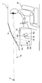
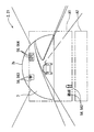
- FIG. 1 is an interior view showing an interior of a host vehicle equipped with a vehicle driving assist system according to an embodiment.
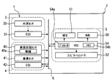
- FIG. 2 is a block diagram illustrating a vehicle driving assist system according to an embodiment.
- FIG. 3 is a structural diagram schematically showing the detailed configuration of the HUD of FIGS.
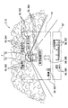
- FIG. 4 is a front view showing a virtual image display state by the HUD of FIGS.
- FIG. 5 is a front view showing a virtual image display state by the HUD of FIGS.
- FIG. 6 is a front view showing a virtual image display state by the HUD of FIGS.
- FIG. 1 is an interior view showing an interior of a host vehicle equipped with a vehicle driving assist system according to an embodiment.
- FIG. 2 is a block diagram illustrating a vehicle driving assist system according to an embodiment.
- FIG. 3 is a structural diagram schematically showing the detailed configuration of the HUD of FIGS.
- FIG. 4 is a front view showing a virtual image display state by the HUD of FIGS.
- FIG. 7 is a front view showing a virtual image display state by the HUD of FIGS.
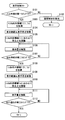
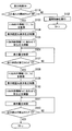
- FIG. 8 is a flowchart showing a display control flow by the HCU of FIG.
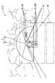
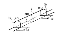
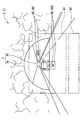
- FIG. 9 is a schematic diagram for explaining the processing contents in S101 and S107 of FIG.
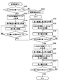
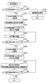
- FIG. 10 is a flowchart showing a modification of FIG.
- FIG. 11 is a flowchart showing a modification of FIG.
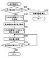
- FIG. 12 is a flowchart showing a modification of FIG.
- FIG. 13 is a flowchart showing a modification of FIG.
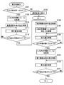
- FIG. 14 is a flowchart showing a modification of FIG.
- FIG. 15 is a flowchart showing a modification of FIG.
- FIG. 16 is a flowchart showing a modification of FIG.
- FIG. 17 is a flowchart showing a modification of FIG.
- FIG. 18 is a front view showing a modification of FIG.
- a vehicle driving assist system 1 according to an embodiment to which the present disclosure is applied is mounted on the host vehicle 2 as shown in FIGS. 1 and 2, and can particularly assist driving of the host vehicle 2 when passing through the tunnel 7. ing.
- the vehicle driving assist system 1 includes a periphery monitoring system 3, a vehicle control system 4, and a display system 5.
- the periphery monitoring system 3, the vehicle control system 4, and the display system 5 are connected to each other via an in-vehicle network 6 such as a LAN (Local Area Network).
- LAN Local Area Network
- the periphery monitoring system 3 includes an external sensor 30 and a periphery monitoring ECU (Electronic Control Unit) 31.
- the external sensor 30 detects obstacles that exist in the external environment of the host vehicle 2 and may collide, such as other vehicles, artificial structures, humans, and animals, and traffic-related objects that exist in the external environment. .
- the external sensor 30 is, for example, one type or plural types of sonar, radar, LIDAR (Light (Detection (and Ranging / Laser Imaging Detection and Ranging), a camera, and the like.
- the sonar is an ultrasonic sensor installed in, for example, the front part or the rear part of the host vehicle 2.
- the sonar detects the obstacle in the detection area by outputting the reflected wave of the ultrasonic wave transmitted to the detection area in the external environment of the host vehicle 2, and outputs a detection signal.
- the radar is a millimeter wave sensor or a laser sensor installed in the front part or the rear part of the host vehicle 2.
- the radar receives the millimeter wave or quasi-millimeter reflected wave transmitted to the detection area in the external environment of the host vehicle 2, thereby detecting an obstacle in the detection area and outputting a detection signal.
- the LIDAR is a laser scanner installed on the roof of the host vehicle 2, for example.
- the LIDAR receives the reflected wave of the laser transmitted to the detection area in the external world of the host vehicle 2, thereby detecting an obstacle in the detection area and outputting a detection signal.
- the camera is a monocular or compound eye camera installed on, for example, a room mirror or a door mirror of the host vehicle 2. The camera captures an image of a detection area in the external environment of the host vehicle 2 to detect an obstacle and a traffic-related object in the detection area and outputs an image signal.
- the periphery monitoring ECU 31 is mainly configured by a microcomputer having a processor and a memory, and is connected to the external sensor 30 and the in-vehicle network 6.
- the surroundings monitoring ECU 31 outputs the obstacle information such as the type of obstacle (here, if the obstacle is another vehicle, including the vehicle type) and the relative position of the obstacle with respect to the host vehicle 2 from the output of the external sensor 30. Acquire based on the signal.
- the periphery monitoring ECU 31 acquires sign information such as speed limit signs and lane signs, travel road information such as white lines and road surface conditions, and tunnel information related to the tunnel 7 based on the output signal of the external sensor 30.
- the vehicle control system 4 includes a vehicle state sensor 40, an occupant sensor 41, and a vehicle control ECU 42.
- the vehicle state sensor 40 is connected to the in-vehicle network 6.
- the vehicle state sensor 40 detects the traveling state of the host vehicle 2.
- the vehicle state sensor 40 is, for example, at least the wireless communication device 40a in the present embodiment among the wireless communication device 40a, the vehicle speed sensor, the rotation speed sensor, the rudder angle sensor, the fuel sensor, the water temperature sensor, and the GPS (Global Positioning System) receiver.
- GPS Global Positioning System
- the wireless communication device 40a is wireless from one or more types of communication devices outside the host vehicle 2, such as other vehicle transmitters or portable terminals for vehicle-to-vehicle communication, and roadside devices for road-to-vehicle communication.
- the wireless communication device 40a includes the tunnel internal information Ii representing the internal status of the tunnel 7 as the tunnel internal / external information I (for example, see FIG. 8) representing the internal / external status of the tunnel 7 through which the host vehicle 2 passes.
- the tunnel external information Io representing the external information of the tunnel 7 is generated.
- As the tunnel internal information Ii at least illuminance information, traffic information, travel route information, and tunnel information are generated.
- at least illuminance information, traffic information, travel route information, and weather information are generated as the tunnel external information Io.
- the illuminance information is physical information representing the external illuminance of the vehicle 2.
- the traffic information includes, for example, obstacle information such as information on the distance between the other vehicle that is an obstacle and the host vehicle 2, traffic information in front of the host vehicle 2, broken vehicle information, accident vehicle information, and fallen object information.
- obstacle information such as information on the distance between the other vehicle that is an obstacle and the host vehicle 2, traffic information in front of the host vehicle 2, broken vehicle information, accident vehicle information, and fallen object information.
- the tunnel information includes, for example, at least the reach distance information among the reach distance information to the entrance 7a and the exit 7b (see, for example, FIGS. 1, 4 to 7 and 9) of the tunnel 7 and the structure information of the entrance 7a and the exit 7b.
- the road information is, for example, one or more types including at least road surface information in the present embodiment among road surface information representing road surface conditions such as a frozen state and shape information representing road shapes such as slopes and curves.
- the weather information includes, for example, weather information representing weather conditions such as sunny weather, rainy weather, cloudy weather, and snowfall, ambient light information representing ambient light conditions such as solar radiation direction, and temperature information representing the outside temperature of the vehicle 2
- weather information representing weather conditions such as sunny weather, rainy weather, cloudy weather, and snowfall
- ambient light information representing ambient light conditions such as solar radiation direction
- temperature information representing the outside temperature of the vehicle 2
- the vehicle speed sensor outputs a vehicle speed signal corresponding to the detection by detecting the vehicle speed of the host vehicle 2.
- the rotation speed sensor detects the engine rotation speed of the internal combustion engine in the host vehicle 2 and outputs a rotation speed signal corresponding to the detection.
- the steering angle sensor detects the steering angle of the host vehicle 2 and outputs a steering angle signal corresponding to the detection.
- the fuel sensor detects the remaining amount of fuel in the fuel tank of the host vehicle 2 and outputs a fuel signal corresponding to the detection.
- the water temperature sensor detects the cooling water temperature of the internal combustion engine in the host vehicle 2 and outputs a water temperature signal corresponding to the detection.
- the GPS receiver acquires position information related to the traveling position of the host vehicle 2 by receiving radio waves transmitted from GPS satellites.
- the passenger sensor 41 is connected to the in-vehicle network 6.
- the occupant sensor 41 detects the state or operation of a user who has boarded the passenger compartment 2a of the host vehicle 2 shown in FIG.
- the occupant sensor 41 is, for example, one type or a plurality of types including at least a power switch among a power switch, a user status monitor, a display setting switch, a turn switch, an automatic control switch, and the like.
- the power switch is operated by the user in the passenger compartment 2a to start the internal combustion engine or the motor generator of the host vehicle 2, and outputs a power signal corresponding to the operation.
- the user state monitor captures the user state on the driver's seat 20 in the passenger compartment 2a with an image sensor, thereby detecting the user state and outputting an image signal.
- the display setting switch is operated by the user to set the display state in the passenger compartment 2a, and outputs a display setting signal corresponding to the operation.
- the turn switch is operated by the user in the passenger compartment 2a to operate the direction indicator of the host vehicle 2, and outputs a turn signal corresponding to the operation.
- the automatic control switch outputs an automatic control signal corresponding to the operation when operated by the user in the passenger compartment 2a in order to instruct automatic control with respect to the traveling state of the host vehicle 2.
- the vehicle control ECU 42 shown in FIG. 2 is mainly composed of a microcomputer having a processor and a memory, and is connected to the in-vehicle network 6.
- the vehicle control ECU 42 is one type or a plurality of types among an engine control ECU, a motor control ECU, a brake control ECU, a steering control ECU, an integrated control ECU, and the like.
- the engine control ECU controls the operation of the throttle actuator and the fuel injection valve of the internal combustion engine according to the operation of the accelerator pedal 26 in the passenger compartment 2a shown in FIG. Accelerate and decelerate.
- the motor control ECU accelerates or decelerates the vehicle speed of the host vehicle 2 by controlling the operation of the motor generator according to the operation of the accelerator pedal 26 in the passenger compartment 2a or automatically.
- the brake control ECU accelerates or decelerates the vehicle speed of the host vehicle 2 by controlling the operation of the brake actuator according to the operation of the brake pedal 27 in the passenger compartment 2a or automatically.
- the steering control ECU adjusts the steering angle of the host vehicle 2 by controlling the operation of the electric power steering according to the operation of the steering handle 24 in the passenger compartment 2a or automatically.
- the integrated control ECU synchronously controls the operations of the other ECUs based on, for example, the output signals of the sensors 40 and 41, the acquisition information of the periphery monitoring ECU 31, and the control information of the ECUs other than itself among the vehicle control ECUs 42.
- the display system 5 is mounted on the host vehicle 2 for visually presenting information.
- the display system 5 includes an HUD 50, an MFD (Multi Function Display) 51, a combination meter 52, and an HCU (Human Machine Interface Control Unit) 54.
- the HUD 50 is installed on the instrument panel 22 in the passenger compartment 2a shown in FIGS.
- the HUD 50 forms a display image 56 representing predetermined information by, for example, a liquid crystal type or scanning type projector 50a.
- the HUD 50 projects the display image 56 formed in this way onto the front windshield 21 as a “projection member” in the host vehicle 2 through an optical system 50 b such as a concave mirror.
- the front windshield 21 is formed of translucent glass, and transmits the foreground 8 existing in front of the host vehicle 2 outside the passenger compartment 2a.
- the light flux of the display image 56 reflected by the front windshield 21 and the light flux from the foreground 8 transmitted through the shield 21 are perceived by the user on the driver seat 20.
- the virtual image of the display image 56 formed at a position ahead of the front windshield 21 is displayed superimposed on a part of the foreground 8 as shown in FIG. Is visible.
- two types of areas A1 and A2 are set in the display area as a range where the virtual image of the display image 56 is displayed.
- the first display area A1 is set in order to superimpose the display image 56 of the virtual image display in association with the specific object in the foreground 8.
- the first display area A1 for the purpose of such association is adjusted by the HUD 50 so that the display image 56 is formed at a far position, for example, about 15 m away from the host vehicle 2 in the foreground 8 forward.
- the second display area A2 is set in order to remove the association with the specific object in the foreground 8 and display the display image 56 in a virtual image.
- the second display area A2 for the purpose of such disassociation is formed from the first display area A1 by the HUD 50 so that the display image 56 is imaged in the foreground 8 forward from the vehicle 2 at a short distance position of about 2 m, for example. Is also adjusted downward and to a small size. That is, in the second display area A2, the display image 56 imaged at a position closer to the host vehicle 2 than in the case of the first display area A1 is displayed as a virtual image.
- the projector 50a and the optical system 50b constituting the HUD 50 may be provided for each of the display areas A1 and A2, respectively. You may provide in common in area
- the first display area A1 as long as at least one type of display image 56 is associated with the specific object in the foreground 8, such disassociated display image 56 may be displayed as a virtual image.
- the second display area A2 as long as at least one type of display image 56 is disassociated from the specific object in the foreground 8, the display image 56 that realizes such association is displayed as a virtual image. May be.
- the display image 56 that the HUD 50 displays as a virtual image in one of the display areas A1 and A2 a plurality of types of images as shown in FIGS. 4 to 7 are prepared in order to assist the user in driving the host vehicle 2.
- the plurality of types of display images 56 include at least an inter-vehicle distance image 560, an exit distance image 561, a road surface image 562, a weather image 563, a temperature image 564, a navigation image 565, a vehicle speed image 566, and a rotation speed image 567. It is.
- the inter-vehicle distance image 560 is displayed in a virtual image in association with another vehicle as a front obstacle in the first display area A1.
- the inter-vehicle distance image 560 represents inter-vehicle distance information with the nearest other vehicle that travels ahead of the host vehicle 2 in the obstacle information as traffic information.
- the inter-vehicle distance image 560 in the standard display state indicates numbers and characters indicating the value and unit of the inter-vehicle distance, characters indicating the meaning of the numbers, and the nearest other vehicle that is the target of the numbers. The figure is made up of.
- the display amount of the inter-vehicle distance image 560 in the simple display state is reduced by omitting the characters indicating the contents.
- the exit distance image 561 is displayed as a virtual image in association with the exit 7b of the tunnel 7 in the first display area A1.
- the exit distance image 561 represents the reach distance information to the nearest exit 7b to which the host vehicle 2 heads among the tunnel information.
- the exit distance image 561 in the standard display state indicates the numbers and characters indicating the value and unit of the reach distance, the characters indicating the meaning of the numbers, and the exit 7b that is the target of the numbers. It consists of figures.
- the exit distance image 561 in the simple display state is reduced in display amount by omitting characters indicating the contents.
- the road surface image 562 is displayed as a virtual image in association with the traveling road ahead of the host vehicle 2 in the first display area A1.
- the road surface image 562 represents road surface information related to the forward traveling road of the host vehicle 2 in the traveling road information.
- a standard display state as shown in FIG. 4 and a simple display state in which the display amount is limited as compared with the standard display state as shown in FIG. 7 are set.
- the road surface image 562 in the standard display state is composed of a figure schematically showing the road surface state and characters showing the contents meant by the figure.
- the display amount of the road image 562 in the simple display state is reduced by omitting the characters indicating the contents.
- the weather image 563 is displayed as a virtual image in the first display area A1 in association with the sky area above the vehicle 2 in front.
- the weather image 563 represents weather information regarding the traveling environment of the host vehicle 2 among the weather information.
- a standard display state as shown in FIG. 4 and a simple display state in which the display amount is limited as compared with the standard display state as shown in FIG. 7 are set.
- the weather image 563 in the standard display state is composed of a figure that schematically shows the weather state and characters that indicate the contents that the figure means.
- the display amount of the weather image 563 in the simple display state is reduced by omitting the characters indicating the contents.
- the temperature image 564 is displayed as a virtual image in the first display area A1 in association with the sky area above the front of the host vehicle 2.
- the temperature image 564 represents temperature information regarding the traveling environment of the host vehicle 2 among the weather information.
- a standard display state as shown in FIG. 4 and a simple display state in which the display amount is limited as compared with the standard display state as shown in FIG. 7 are set.
- the temperature image 564 in the standard display state is composed of numbers and letters indicating the value and unit of the outside air temperature, and letters indicating the contents that the numbers mean.
- the display amount of the temperature image 564 in the simple display state is reduced by omitting characters indicating the contents.
- the navigation image 565 is displayed as a virtual image in association with the traveling road ahead of the host vehicle 2 in the first display area A1.
- the navigation image 565 represents navigation information for guiding a travel route toward the host vehicle 2.
- the navigation image 565 is composed of at least a figure showing the planned travel route of the host vehicle 2 in the navigation information.
- the navigation information can be acquired based on the map information stored in the memory 54b and the output signal of the vehicle state sensor 40 in the HCU 54 described in detail later.
- the vehicle speed image 566 is displayed as a virtual image at a certain location not associated with the specific object in the second display area A2.
- the vehicle speed image 566 represents vehicle speed information based on an output signal from the vehicle speed sensor in the vehicle state sensor 40.
- the vehicle speed image 566 is composed of numbers and characters indicating the value and unit of the vehicle speed, respectively.
- the rotational speed image 567 is displayed as a virtual image along with the vehicle speed image 566 at a fixed location that is not associated with the specific object in the second display area A2.
- the rotational speed image 567 represents engine rotational speed information based on an output signal from the rotational speed sensor of the vehicle state sensor 40.
- the engine speed image 567 is composed of numerals and characters indicating the engine speed value and unit, respectively.
- the display image 56 in addition to the above images 560, 561, 562, 563, 564, 565, 566, 567, for example, music information or video information provided in the passenger compartment 2a of the host vehicle 2 or the like.
- An image or the like related to may be adopted.
- a translucent combiner that is arranged on the instrument panel 22 and transmits the foreground 8 in cooperation with the front windshield 21, a virtual image display can be realized by projecting the display image 56 on the combiner. Is possible.
- the MFD 51 is installed in the center console 23 in the passenger compartment 2a shown in FIG.
- the MFD 51 displays a real image of an image formed so as to show predetermined information on one or a plurality of liquid crystal panels so that it can be visually recognized by a user on the driver's seat 20.
- As the real image display by the MFD 51 display of an image indicating one type or a plurality of types of information among navigation information, music information, video information, and the like is employed.
- the combination meter 52 is installed on the instrument panel 22 in the passenger compartment 2a.
- the combination meter 52 displays vehicle information related to the host vehicle 2 so that the user on the driver's seat 20 can visually recognize the vehicle information.
- the combination meter 52 is a digital meter that displays vehicle information by an image formed on a liquid crystal panel, or an analog meter that displays vehicle information by indicating a scale with a pointer.
- a display indicating one type or a plurality of types of information among information such as a vehicle speed, an engine speed, a remaining fuel amount, a coolant temperature, a turn switch, and an automatic control switch is adopted. .
- the HCU 54 is mainly composed of a microcomputer having a processor 54a and a memory 54b, and is connected to the display elements 50, 51, 52 of the display system 5 and the in-vehicle network 6.
- the HCU 54 synchronously controls the operation of the display elements 50, 51, 52.
- the HCU 54 performs operation control thereof based on, for example, acquisition information or output signals of the ECU 31 and sensors 40 and 41, control information of the ECU 42, storage information of the memory 54b, acquisition information of the HCU 54 itself, and the like.
- the memory 54b of the HCU 54 and the memories of other various ECUs are respectively configured by using one or a plurality of storage media such as a semiconductor memory, a magnetic medium, or an optical medium.
- the HCU 54 of the present embodiment functions as a “vehicle display control device” so as to read the display image 56 stored as data in the memory 54 b and display the virtual image on the HUD 50.
- the HCU 54 functionally realizes each step of the display control flow shown in FIG. 8 by executing a display control program by the processor 54a.
- the display control flow starts in response to an ON operation of a power switch as the occupant sensor 41 and ends in response to an OFF operation of the switch.
- “S” in the display control flow means each step.
- each of the memories of the built-in ECU of the display elements 50, 51, 52 or each of those memories and the memory 54 b of the HCU 54 May be realized by sharing a plurality of memories.
- the timing at which the execution of S ⁇ b> 101 is started is the first timing T ⁇ b> 1 when the traveling position of the host vehicle 2 is before the entrance 7 a of the tunnel 7.
- the first timing T1 is adjusted to the timing when the traveling position of the host vehicle 2 arrives from the entrance 7a to the front by a set distance L1 as shown in FIG.
- the set distance L1 for determining the first timing T1 is based on at least one type or a plurality of types of vehicle speed information, traffic information, tunnel information, travel route information, weather information, and the like of the host vehicle 2, for example. It is variably set to ensure safety.
- the host vehicle 2 when the host vehicle 2 is traveling on a general road having a prescribed legal maximum speed, the host vehicle 2 is traveling on an expressway having a speed of 100 m or higher than the ordinary road.
- the set distance L1 is set to 200 m or the like.
- the process proceeds to S102 to execute normal control of virtual image display in each of the display areas A1 and A2, and then returns to S101.
- the normal control as shown in FIG. 4, as the display image 56, an inter-vehicle distance image 560, an exit distance image 561, a road surface image 562, a weather image 563, a temperature image 564, and a navigation image 565 are displayed in the first display area A1.
- a virtual image is displayed.
- the inter-vehicle distance image 560 and the road surface image 562 are displayed in bright red
- the weather image 563 and the temperature image 564 are displayed in bright yellow
- the navigation image 565 is displayed in bright blue.
- a vehicle speed image 566 and a rotation speed image 567 are displayed as virtual images in the second display area A2 as the display image 56 as shown in FIG.
- the vehicle speed image 566 and the rotation speed image 567 are displayed in white.
- each image 560, 561, 562, 563, 564, 565, 566, 567 can be adjusted by, for example, the RGB gradation value in the projector 50a, the light emission luminance value of the light source in the projector 50a, or the like. It is.
- the virtual image display starts when the host vehicle 2 exceeds the travel position separated from the entrance 7a of the tunnel 7 by a predetermined distance longer than the set distance L1 outside the tunnel 7. ing.
- the process proceeds to S103, whereby the pieces of information Ii and Io that are the tunnel inside / outside information I are acquired from the outside through the wireless communication device 40a.
- the tunnel internal information Ii At this time, at least illuminance information, traffic information, travel route information, and tunnel information regarding the internal state of the forward tunnel 7 are acquired as the tunnel internal information Ii.
- at least illuminance information, traffic information, travel route information, and weather information relating to the external situation before the front tunnel 7 is acquired as the tunnel external information Io.
- the provision information provided to the user inside the tunnel 7 is limited to the tunnel internal information Ii among the tunnel internal / external information I acquired in S103.
- the display range and display color are limited.
- the information provided to the user includes the inter-vehicle distance information and the reaching distance information represented by the inter-vehicle distance image 560 and the exit distance image 561 in the first display area A1 as the tunnel internal information Ii necessary for driving the host vehicle 2, respectively. Limited. Therefore, the information represented by the road surface image 562, the weather image 563, the temperature image 564, and the navigation image 565 in the first display area A1, and the information represented by the vehicle speed image 566 and the rotation speed image 567 in the second display area A2. The information is not provided to the user.
- the timing at which the execution of S104 is started can be assumed as the first timing T1 before the entrance 7a of the tunnel 7. Therefore, the provision information in the first display area A1 is substantially from the first timing T1 to the second timing T2, which will be described later, that is, from before the entrance 7a outside the tunnel 7 to before the exit 7b inside the tunnel 7. It is limited to the inter-vehicle distance information and the reach distance information.
- the restriction process restricts the display range of the display image 56 to only the first display area A1, and the display color of the display image 56 is the display color of the inter-vehicle distance image 560 and the exit distance image 561 (for example, during normal control). This is also the process of limiting to red) of the same system.
- the brightness of the display image 56 representing the tunnel internal information Ii restricted in S104 is adjusted according to the tunnel internal information Ii acquired in S103. Specifically, the inter-vehicle distance image 560 and the exit distance image 561 representing the inter-vehicle distance information and the reaching distance information as the limited tunnel internal information Ii are matched with the illuminance information inside the front tunnel 7 in the tunnel internal information Ii. The brightness is adjusted. At this time, in particular, the brightness of the inter-vehicle distance image 560 and the exit distance image 561 is adjusted to be darker than that in the normal control in S102 in accordance with the illuminance information inside the front tunnel 7. As a result, for example, in the present embodiment, the display color of the inter-vehicle distance image 560 and the exit distance image 561 is dark red.
- the timing at which the execution of S105 is started can also be assumed as the first timing T1 before the entrance 7a of the tunnel 7. Therefore, an image to be displayed in the first display area A1 from the first timing T1 to the second timing T2, which will be described later, that is, from before the entrance 7a outside the tunnel 7 to before the exit 7b inside the tunnel 7.
- the brightness of 560, 561 is adjusted according to the illuminance information. Therefore, in the present embodiment, the first timing T1 corresponds to “entrance adjustment timing”.
- the brightness of the images 560 and 561 can be adjusted by, for example, RGB gradation values in the projector 50a, light emission luminance values of the light source in the projector 50a, and the like.
- the display image 56 of the brightness limited to the information Ii in S104 and adjusted in S105 is displayed by the HUD 50 as a virtual image.
- both the inter-vehicle distance image 560 and the exit distance image 561 whose brightness is suppressed in the first display area A1 as compared with the normal control in S102 are simply displayed as shown in FIGS.
- a virtual image is displayed in the state. In other words, the display amount is limited.
- the virtual image display of the road surface image 562, the weather image 563, the temperature image 564, and the navigation image 565 in the first display area A1 and the virtual image display of the vehicle speed image 566 and the rotation speed image 567 in the second display area A2, Disappear.
- the timing at which the execution of S106 is started can also be assumed as the first timing T1 that is before the entrance 7a of the tunnel 7. Therefore, from the first timing T1 to the second timing T2 to be described later, that is, from before the entrance 7a outside the tunnel 7 to before the exit 7b inside the tunnel 7, the display image 56 is displayed in the first display area A1.
- the display amount by is limited to the display amount by the images 560 and 561 in the simple display state. Therefore, FIG. 5 shows a display state from the first timing T ⁇ b> 1 to the timing when the host vehicle 2 enters the entrance 7 a of the tunnel 7 outside the tunnel 7.
- FIG. 5 shows a display state from the first timing T ⁇ b> 1 to the timing when the host vehicle 2 enters the entrance 7 a of the tunnel 7 outside the tunnel 7.
- the first timing T1 also corresponds to “entrance restriction timing”.
- the process proceeds to S107, and the timing at which the execution of S107 is started is the second timing when the traveling position of the host vehicle 2 is before the exit 7b of the tunnel 7. It is determined whether or not T2.
- the second timing T2 is adjusted to a timing at which the traveling position of the host vehicle 2 arrives from the exit 7b to the front by a set distance L2, as shown in FIG.
- the set distance L2 for determining the second timing T2 is variably set similarly to the set distance L1. Therefore, for example, when the host vehicle 2 is traveling on a general road having a prescribed legal maximum speed, the host vehicle 2 is traveling on an expressway having a speed of 100 m or higher than the ordinary road. In this case, the set distance L2 is set to 200 m or the like.
- the provided information provided to the user before the exit 7b of the tunnel 7 is limited to the tunnel external information Io in the tunnel internal / external information I acquired in S108.
- the display range and display color are limited.
- the information provided to the user includes road surface information and weather information represented as a road surface image 562, a weather image 563, and a temperature image 564 in the first display area A1, as tunnel external information Io necessary for driving the host vehicle 2. And temperature information. Therefore, the information represented by the inter-vehicle distance image 560, the exit distance image 561, and the navigation image 565 in the first display area A1, and the information represented by the vehicle speed image 566 and the rotation speed image 567 in the second display area A2 are transmitted to the user. Is not provided.
- the timing at which the execution of S109 is started can be assumed as the second timing T2 before the exit 7b of the tunnel 7. Therefore, the provision information in the first display area A1 is the road surface information from the second timing T2 until the third timing T3 described later, that is, from before the exit 7b in the tunnel 7 to the exit at the exit 7b. It is limited to weather information and temperature information. Further, the restriction process restricts the display range of the display image 56 to only the first display area A1, and the display color of the display image 56 is the same as the display color of road surface information, weather information, and temperature information (for example, the same as in normal control). It is also a process limited to the system yellow).
- the brightness of the display image 56 representing the tunnel external information Io restricted in S109 is adjusted according to the tunnel external information Io acquired in S108.
- road surface information 562, weather image 563, and temperature image 564 representing road surface information, weather information, and temperature information as restricted tunnel external information Io are illuminance outside the front exit 7b of the tunnel external information Io.
- the brightness is adjusted according to the information and weather information.
- the brightness of the road surface image 562, the weather image 563, and the temperature image 564 is adjusted to be brighter than that at the time of adjustment in S105 according to the illuminance information and weather information outside the front exit 7b.
- the display color of the road surface image 562, the weather image 563, and the temperature image 564 is dark yellow.
- the timing at which the execution of S110 is started can also be assumed as the second timing T2 before the exit 7b of the tunnel 7. Therefore, the image 562 displayed in the first display area A1 from the second timing T2 until the third timing T3 described later, that is, from before the exit 7b in the tunnel 7 to the exit at the exit 7b.
- the brightness of 563 and 564 is adjusted according to the illuminance information and the weather information. Therefore, in the present embodiment, the second timing T2 corresponds to “exit adjustment timing”.
- the brightness of the images 562, 563, and 564 can be adjusted by, for example, RGB gradation values in the projector 50a, light emission luminance values of the light sources in the projector 50a, and the like.
- the display image 56 having the brightness limited to the information Io in S109 and adjusted in S110 is displayed as a virtual image by the HUD 50.
- the road surface image 562, the weather image 563, and the temperature image 564, which are brighter than those during the adjustment in S105 in the first display area A1 are all in a simple display state as shown in FIG. Is displayed as a virtual image. In other words, the display amount is limited.
- the virtual image display of the inter-vehicle distance image 560, the exit distance image 561, and the navigation image 565 in the first display area A1, and the virtual image display of the vehicle speed image 566 and the rotation speed image 567 in the second display area A2 disappear. .
- the timing at which the execution of S111 is started can also be assumed as the second timing T2 before the exit 7b of the tunnel 7. Therefore, from the second timing T2 until a later-described third timing T3, that is, from before the exit 7b in the tunnel 7 to the exit at the exit 7b, display by the display image 56 in the first display area A1.
- the amount is limited to the display amount by the images 562, 563, and 564 in the simple display state.
- the second timing T2 also corresponds to “exit restriction timing”.
- the timing at which the execution of S112 is started by shifting to S112 after the completion of the execution of S111 is the third timing T3 when the host vehicle 2 exits the exit 7b of the tunnel 7. It is determined whether or not. As a result, when a negative determination is made, the process returns to S111, whereas when an affirmative determination is made, the process returns to S101.
- the functional part that executes S103 and S108 corresponds to an “information acquisition unit”
- the functional part that executes S105 and S110 corresponds to an “adjustment unit”
- S104 The functional part that executes 106, S109, and S111 corresponds to a “restriction unit”.
- the brightness of the display image 56 is adjusted in accordance with the tunnel internal information Ii acquired by the HCU 54 at the first timing T1 before the entrance 7a of the tunnel 7.
- the tunnel internal information Ii representing the internal state of the tunnel 7 is transmitted and acquired from outside the host vehicle 2 by wireless communication, the internal state immediately before the host vehicle 2 enters the entrance 7a It can be reflected in a timely and accurate manner. Therefore, according to the timely and accurate adjustment in accordance with the tunnel internal information Ii, the display image 56 having a brightness capable of ensuring visual legibility with respect to the foreground 8 serving as a display background in the host vehicle 2 is displayed at the entrance 7a. A virtual image can be displayed in response to the approach to the vehicle.
- the brightness of the display image 56 is adjusted according to the illuminance information inside the tunnel 7 among the tunnel internal information Ii acquired by the HCU 54.
- the illuminance information is transmitted and acquired by wireless communication from the outside of the host vehicle 2 as the tunnel internal information Ii representing the internal state of the tunnel 7, the external illuminance inside the tunnel 7 immediately before entering the entrance 7a is obtained. , Timely and accurately reflected. Therefore, according to the adjustment according to timely and accurate illuminance information, a display image 56 having a brightness that can ensure visual legibility with respect to the external illuminance inside the tunnel 7 is converted into a virtual image according to the approach to the entrance 7a. It can be displayed.
- the first display area A1 that associates the display image 56 with the specific object in the foreground 8 and the first display area A2 that has been removed from the association are displayed on the first display area A1.
- the brightness of the display image 56 in the area A1 is adjusted. According to this, since the brightness of the display image 56 that is easy for the user to gaze can be adjusted preferentially by associating with the specific object, the visual legibility for the foreground 8 is ensured according to the approach to the entrance 7a. It becomes possible.
- the brightness of the display image 56 is adjusted in accordance with the tunnel external information Io acquired by the HCU 54 at the second timing T2 before the exit 7b of the tunnel 7.
- the tunnel external information Io representing the external situation of the tunnel 7 is transmitted and acquired by wireless communication from the outside of the own vehicle 2, the external situation immediately before the exit of the own vehicle 2 at the exit 7b is obtained. It can be reflected in a timely and accurate manner. Therefore, according to the timely and accurate adjustment in accordance with the tunnel external information Io, the display image 56 having a brightness that can ensure visual legibility with respect to the foreground 8 serving as a display background in the host vehicle 2 is displayed on the exit 7b. It is possible to display a virtual image in response to the exit at.
- the brightness of the display image 56 is adjusted in accordance with the illuminance information outside the tunnel 7 out of the tunnel external information Io acquired by the HCU 54.
- the illuminance information is transmitted and acquired by wireless communication from the outside of the vehicle 2 as the tunnel external information Io representing the external situation of the tunnel 7, the external illuminance outside the tunnel 7 immediately before exiting at the exit 7b is obtained. , Timely and accurately reflected. Therefore, according to the timely and accurate adjustment in accordance with the illuminance information, the display image 56 having a brightness that can ensure visual legibility with respect to the external illuminance outside the tunnel 7 is changed to a virtual image according to the exit at the exit 7b. It can be displayed.
- the brightness of the display image 56 is adjusted in accordance with weather information outside the tunnel 7 out of the tunnel external information Io acquired by the HCU 54.
- the weather information is transmitted and acquired by wireless communication from the outside of the vehicle 2 as the tunnel external information Io representing the external situation of the tunnel 7, the weather condition outside the tunnel 7 immediately before exiting at the exit 7b is obtained.
- Timely and accurately reflected Therefore, according to such adjustment in accordance with timely and accurate weather information, a display image 56 having a brightness that can ensure visual legibility with respect to weather conditions outside the tunnel 7 can be used to exit at the exit 7b. Accordingly, a virtual image can be displayed.
- the first display area A1 for associating the display image 56 with the specific object in the foreground 8 and the second display area A2 for which the association has been removed also at the second timing T2 of the present embodiment.
- the brightness of the display image 56 in the display area A1 is adjusted. According to this, the brightness of the display image 56 that is easy for the user to gaze can be preferentially adjusted by associating with the specific object, so that the visual legibility for the foreground 8 is ensured according to the exit at the exit 7b. It becomes possible.
- the information provided by the display image 56 is limited to the tunnel internal information Ii among the tunnel internal / external information I acquired by the HCU 54.
- the tunnel internal information Ii representing the internal state of the tunnel 7 is transmitted and acquired by wireless communication from the outside of the own vehicle 2 as the tunnel internal / external information I representing the inside / outside state of the tunnel 7, the own vehicle 2
- the internal situation at the time of traveling can be reflected in a timely and accurate manner. Therefore, according to the limitation to the timely and accurate information type, when traveling inside the tunnel 7, the information provided in an amount of information that can ensure visual legibility with respect to the foreground 8 that is the display background in the host vehicle 2.
- the display image 56 representing the provided information can be displayed as a virtual image.
- the information provided by the display image 56 is limited to the tunnel internal information Ii necessary for driving the host vehicle 2 out of the tunnel internal / external information I acquired by the HCU 54.
- the tunnel internal information Ii can be provided within the tunnel 7 where it is difficult for the user to accept the side effect, by narrowing down the amount of information necessary for driving the host vehicle 2. Therefore, it is possible to ensure the legibility of the display image 56 with respect to the foreground 8 while giving the user a sense of security when traveling inside the tunnel 7.
- the restriction to the tunnel internal information Ii is started from the first timing T1 before the entrance 7a of the tunnel 7.
- the information provided by the display image 56 can be reliably limited to the tunnel internal information Ii from the time when the host vehicle 2 enters the entrance 7a inside the tunnel 7, so that the legibility of the foreground 8 can be ensured. It becomes.
- the display image 56 is limited to the tunnel internal information Ii, but also the display color of the display image 56 representing the tunnel internal information Ii is limited. According to these information restrictions and display color restrictions, it is possible to reliably ensure the visual legibility required for the foreground 8 that is required when the user travels inside the tunnel 7 where it is difficult for a user to look aside.
- the provided information by the display image 56 is not limited to the tunnel internal information Ii, but the display range of the display image 56 representing the tunnel internal information Ii is also limited. According to these information restrictions and display range restrictions, it is possible to reliably ensure the visual legibility required for the foreground 8 that is required when traveling inside the tunnel 7 where it is difficult for the user to look aside.
- the information provided by the display image 56 is not limited to the tunnel internal information Ii, but the display amount of the display image 56 representing the tunnel internal information Ii is also limited. . According to these information restrictions and display quantity restrictions, it is possible to reliably ensure the visual legibility required for the foreground 8 that is required when traveling inside the tunnel 7 where it is difficult for the user to look aside.
- the first display among the first display area A1 that associates the display image with the specific object in the foreground 8 and the second display area A2 that has been removed from the association.
- the provided information in the area A1 is limited to the tunnel internal information Ii. According to this, it is possible to preferentially reduce the amount of information provided by the display image 56 that is easy for the user to gaze by associating with the specific object. It can be secured.
- the information provided by the display image 56 is replaced with the tunnel internal information Ii of the tunnel internal / external information I acquired by the HCU 54.
- the tunnel external information Io representing the external situation of the tunnel 7 is acquired and transmitted by wireless communication from the outside of the host vehicle 2 as the tunnel internal / external information I representing the internal / external situation of the tunnel 7.
- the external situation immediately before leaving can be reflected in a timely and accurate manner.
- the provided information is narrowed down to the amount of information that can ensure visual legibility for the foreground 8 that is the background of display in the own vehicle 2, and the provided information is reduced.
- the displayed display image 56 can be displayed as a virtual image in accordance with the exit at the exit 7b.
- the information provided by the display image 56 is limited to the tunnel external information Io necessary for driving the host vehicle 2 out of the tunnel internal / external information I acquired by the HCU 56.
- the tunnel external information Io can be provided by narrowing down the amount of information necessary for driving the host vehicle 2 immediately before exiting at the exit 7b where it is difficult for the user to accept a side look. Therefore, it is possible to ensure the visual legibility of the display image 56 with respect to the foreground 8 while giving the user a sense of security in accordance with the exit at the exit 7b.
- the display color, display range, and display amount of the display image 56 representing the tunnel external information Io are limited in accordance with the processing inside the tunnel 7 described above. Become. Therefore, it is possible to reliably ensure the visual legibility required for the foreground 8 in accordance with the exit at the exit 7b where it is difficult for the user to accept a side look.
- the provided information in the display area A1 is limited to the tunnel external information Io. According to this, it is possible to preferentially reduce the amount of information provided by the display image 56 that is easy for the user to gaze by associating with the specific object, so that the visual legibility for the foreground 8 can be reduced according to the exit at the exit 7b. Can be secured.
- the visual legibility of the display image 56 displayed as a virtual image with respect to the foreground 8 inside and outside the tunnel 7 serving as a display background is improved. It is possible to ensure.
- the brightness of each image 560, 561, 562, 563, 564, 565, 566, 567 is set to S105 by sequentially shifting from S103 to S113, S114. Except for the adjustment according to the above, virtual image display similar to the normal control in S102 may be executed.
- S115 following S114 it is determined whether or not the timing at which the execution of S115 is started is the fourth timing T4 when the host vehicle 2 enters the entrance 7a of the tunnel 7. As a result, when a negative determination is made, the process returns to S114, whereas when an affirmative determination is made, the process proceeds to S104.
- the timing at which the execution of S118 is started by executing S119 instead of S101 is the fourth timing when the host vehicle 2 enters the entrance 7a of the tunnel 7. You may determine whether it is T4. As a result, if a negative determination is made, the process proceeds to S102, whereas if an affirmative determination is made, the process proceeds to S103.
- each image 560, 561, 562, 563, 564, 565, 566, 567 is set according to S110 by sequentially shifting from S108 to S120, S121. Except for the adjustment, virtual image display similar to the normal control in S102 may be executed.
- S122 following S121 it is determined whether or not the timing at which execution of S122 is started is the third timing T3 when the host vehicle 2 exits the exit 7b of the tunnel 7. As a result, when a negative determination is made, the process returns to S121, whereas when an affirmative determination is made, the process returns to S101.
- the timing at which the execution of S 126 is started is the third timing at which the host vehicle 2 exits the exit 7 b of the tunnel 7. You may determine whether it is T3. As a result, when a negative determination is made, the process returns to S106, whereas when an affirmative determination is made, the process proceeds to S101.
- any one of the modification examples 1 to 3 and any one of the modification examples 4 to 6 may be combined.
- FIG. 16 shows Modification 7 in which Modification 1 and Modification 4 are combined
- FIG. 17 shows Modification 7 in which Modification 2 and Modification 5 are combined.
- the characters indicating the unit in the standard display state are used. It may be omitted.
- the brightness adjustment in S105 is performed in addition to or in place of the illuminance information, for example, according to traveling road information (specifically road surface state), external light information (specifically solar radiation direction), or the like. May be executed.
- the brightness adjustment in S110 is performed in addition to or in place of at least one of the illuminance information and the weather information, for example, traveling road information (specifically, road surface state) and external light information (specifically, (Solar radiation direction) etc. may be performed.
- information restricted in S104 of the modification 11 As provided information restricted in S104 of the modification 11, as long as it becomes the tunnel internal information Ii necessary for driving the host vehicle 2, traffic information other than the inter-vehicle distance information and the reach distance information may be adopted. Good. Provided information limited in S109 of the modified example 12 is as long as the tunnel external information Io necessary for driving the host vehicle 2, for example, inter-vehicle distance information or traffic jam information other than road surface information, weather information, and temperature information, etc. May be adopted.
- the display image 56 representing the provided provision information is displayed as a virtual image in S106 or S111.
- At least the latter of the display color and display range of the display image 56 is limited by adopting all the provision information in the display areas A1 and A2 during normal control without being limited in S104. You don't have to.
- As a modified example 16 by restricting at least the latter among the display color and display range of the display image 56 by adopting all the provision information in the display areas A1 and A2 at the time of normal control without being limited in S109. You don't have to.
- the display image 56 representing the provided provision information is displayed as a virtual image in S106 or S111.
- the display amount of the display image 56 may not be limited by adopting the standard display state instead of the simple display state in S106.
- the display amount of the display image 56 may not be limited by adopting the standard display state instead of the simple display state in S111.
- At least one type of provision information in the second display area A2 at the time of normal control is adopted without restriction in S104, and the provision information in the second display area A2 in S105.
- the brightness may be adjusted similarly to the provision information in the first display area A1.
- at least one type of provision information in the second display area A2 at the time of normal control is adopted without restriction in S109, and the provision information in the second display area A2 in S110.
- the brightness may be adjusted similarly to the provision information in the first display area A1.
- the display image 56 representing the provided provision information is displayed as a virtual image in S106 or S111.
- the virtual image display of the display image 56 in the second display area A2 may not be adopted.
- the display image 56 whose information is limited and brightness is adjusted by the display control flow may be displayed as a virtual image in the second display area A2 instead of the first display area A1.
- the virtual image display of the display image 56 in the first display area A1 may not be employed in the modified example 22.
- At least a part of the steps of the display control flow may be realized in hardware by one or a plurality of ICs instead of functionally realized by the HCU 54.
- one type or a plurality of types of the peripheral monitoring ECU 31 and the display control ECUs of the display elements 50, 51 and 52 may function as a “vehicle display control device”. Good.
- each step is expressed as S101, for example. Further, each step can be divided into a plurality of sub-steps, while a plurality of steps can be combined into one step.
- the embodiment, configuration, and aspect of the vehicle driving assist system configured to include the vehicle display control device and the vehicle display control device according to one aspect of the present disclosure have been exemplified, but the embodiment, configuration according to the present disclosure
- the embodiments are not limited to the above-described embodiments, configurations, and aspects.
- embodiments, configurations, and aspects obtained by appropriately combining technical sections disclosed in different embodiments, configurations, and aspects are also included in the scope of the embodiments, configurations, and aspects according to the present disclosure.
Landscapes
- Engineering & Computer Science (AREA)
- Mechanical Engineering (AREA)
- Chemical & Material Sciences (AREA)
- Combustion & Propulsion (AREA)
- Transportation (AREA)
- Physics & Mathematics (AREA)
- General Physics & Mathematics (AREA)
- Multimedia (AREA)
- Theoretical Computer Science (AREA)
- Signal Processing (AREA)
- Computer Hardware Design (AREA)
- Instrument Panels (AREA)
- Transforming Electric Information Into Light Information (AREA)
- Testing, Inspecting, Measuring Of Stereoscopic Televisions And Televisions (AREA)
Abstract
車両用表示制御装置は、前景(8)を透過する投影部材(21)へ表示画像(56)を投影して、表示画像をユーザにより視認可能に虚像表示させるヘッドアップディスプレイ(50)の搭載された自車両(2)において、当該虚像表示を制御する。車両用表示制御装置は、自車両の外部から無線通信により送信されてトンネル(7)の内部状況を表したトンネル内部情報(Ii)を、取得する情報取得ユニット(S103)と、トンネルの入口(7a)手前となる入口調整タイミング(T1)にて、情報取得ユニットにより取得されたトンネル内部情報に合わせて表示画像の明るさを調整する調整ユニット(S105)とを、備える。
Description
本出願は、2016年8月11日に出願された日本国特許出願2016-158319号に基づくものであり、ここにその記載内容を参照により援用する。
本開示は、車両用表示制御装置及びそれを含んで構成される車両運転アシストシステムに、関する。
自車両において前景を透過する投影部材へ表示画像を投影して、当該表示画像をユーザにより視認可能に虚像表示させるヘッドアップディスプレイ(Head-up Display。以下、HUDという。)は、従来より知られている。こうしたHUDは、例えばユーザによる自車両の運転をアシストするような車両運転アシストシステム等に、広く利用されている。
さて、HUDによる虚像表示を制御するために特許文献1には、トンネルの出入口を通過する前に、トンネル情報に基づいて表示画像の明るさを変化させる車両用表示制御技術が、開示されている。ここでトンネル情報としては、トンネルの出入口に関する位置情報及び形状情報が、採用されている。
しかし、特許文献1の開示技術においてトンネル情報は、ナビゲーション装置又は自車両と通信可能なサーバ装置に記憶された地図データに過ぎないため、トンネルの内外状況をタイムリー且つ正確には反映していない事態が想定される。このように、タイムリー且つ正確ではないトンネル情報に基づいて虚像表示される表示画像は、自車両において表示の背景となる前景に対して、視認による判読性(以下、「視認判読性」という。)の低下を招くおそれがあった。
本開示は、自車両において表示の背景となるトンネル内外の前景に対して、虚像表示される表示画像の視認判読性を確保する車両用表示制御装置及び車両運転アシストシステムを、提供することを目的とする。
本開示の第一開示によれば、前景を透過する投影部材へ表示画像を投影して、表示画像をユーザにより視認可能に虚像表示させるヘッドアップディスプレイの搭載された自車両において、当該虚像表示を制御する車両用表示制御装置が提供される。車両用表示制御装置は、自車両の外部から無線通信により送信されてトンネルの内部状況を表したトンネル内部情報を、取得する情報取得ユニットと、トンネルの入口手前となる入口調整タイミングにて、情報取得ユニットにより取得されたトンネル内部情報に合わせて表示画像の明るさを調整する調整ユニットとを、備える。
このような第一開示によると、トンネルの入口手前となる入口調整タイミングには、情報取得ユニットにより取得されたトンネル内部情報に合わせて、表示画像の明るさが調整される。ここで、トンネルの内部状況を表したトンネル内部情報は、自車両の外部から無線通信により送信されて取得されるので、トンネル入口への自車両の進入直前における当該内部状況を、タイムリー且つ正確に反映することができる。故に、タイムリー且つ正確なトンネル内部情報に合わせた調整によれば、自車両において表示の背景となる前景に対して視認判読性を確保可能な明るさの表示画像を、トンネル入口への進入に応じて虚像表示し得るのである。
また、本開示の第二開示によれば、前景を透過する投影部材へ表示画像を投影して、表示画像をユーザにより視認可能に虚像表示させるヘッドアップディスプレイの搭載された自車両において、当該虚像表示を制御する車両用表示制御装置が提供される。車両用表示制御装置は、自車両の外部から無線通信により送信されてトンネルの外部状況を表したトンネル外部情報を、取得する情報取得ユニットと、トンネルの出口手前となる出口調整タイミングにて、情報取得ユニットにより取得されたトンネル外部情報に合わせて表示画像の明るさを調整する調整ユニットとを、備える。
こうした第二開示によると、トンネルの出口手前となる出口調整タイミングには、情報取得ユニットにより取得されたトンネル外部情報に合わせて、表示画像の明るさが調整される。ここで、トンネルの外部状況を表したトンネル外部情報は、自車両の外部から無線通信により送信されて取得されるので、トンネル出口での自車両の退出直前における当該外部状況を、タイムリー且つ正確に反映することができる。故に、タイムリー且つ正確なトンネル外部情報に合わせた調整によれば、自車両において表示の背景となる前景に対して視認判読性を確保可能な明るさの表示画像を、トンネル出口での自車両退出に応じて虚像表示し得るのである。
さらに、本開示の第三開示によれば、前景を透過する投影部材へ表示画像を投影して、表示画像をユーザにより視認可能に虚像表示させるヘッドアップディスプレイの搭載された自車両において、当該虚像表示を制御する車両用表示制御装置が提供される。車両用表示制御装置は、自車両の外部から無線通信により送信されてトンネルの内外状況を表したトンネル内外情報を、取得する情報取得ユニットと、表示画像によりユーザへ提供する提供情報を、情報取得ユニットにより取得されたトンネル内外情報のうち、トンネルの内部状況を表したトンネル内部情報に、トンネルの内部にて制限する制限ユニットとを、備える。
こうした第三開示によると、トンネル内部では、情報取得ユニットにより取得されたトンネル内外情報のうちトンネル内部情報に、表示画像による提供情報が制限される。ここで、トンネルの内部状況を表したトンネル内部情報は、トンネルの内外状況を表したトンネル内外情報として自車両の外部から無線通信により送信されて取得されるので、自車両走行時における当該内部状況を、タイムリー且つ正確に反映することができる。故に、タイムリー且つ正確な情報種類への制限によれば、トンネル内部での走行時には、自車両において表示の背景となる前景に対して視認判読性を確保可能な情報量に提供情報を絞って、当該提供情報を表した表示画像を虚像表示し得るのである。
またさらに、本開示の第四開示によれば、自車両の運転をアシストする車両運転アシストシステムが提供される。車両運転アシストシステムは、第一~第三開示のうちいずれかの車両用表示制御装置と、HUDとを、含んで構成される。
このような第四開示では、上述した第一~第三開示のうちいずれかの車両用表示制御装置により、自車両において表示の背景となるトンネル内外の前景に対して、虚像表示される表示画像の視認判読性を確保可能となる。
本開示についての上記および他の目的、特徴や利点は、添付図面を参照した下記詳細な説明から、より明確になる。添付図面において、
図1は、一実施形態による車両運転アシストシステムを搭載した自車両の車室内を示す内観図であり、
図2は、一実施形態による車両運転アシストシステムを示すブロック図であり、
図3は、図1,2のHUDの詳細構成を模式的に示す構造図であり、
図4は、図1~3のHUDによる虚像表示状態を示す正面図であり、
図5は、図1~3のHUDによる虚像表示状態を示す正面図であり、
図6は、図1~3のHUDによる虚像表示状態を示す正面図であり、
図7は、図1~3のHUDによる虚像表示状態を示す正面図であり、
図8は、図2のHCUによる表示制御フローを示すフローチャートであり、
図9は、図8のS101,S107における処理内容を説明するための模式図であり、
図10は、図8の変形例を示すフローチャートであり、
図11は、図8の変形例を示すフローチャートであり、
図12は、図8の変形例を示すフローチャートであり、
図13は、図8の変形例を示すフローチャートであり、
図14は、図8の変形例を示すフローチャートであり、
図15は、図8の変形例を示すフローチャートであり、
図16は、図8の変形例を示すフローチャートであり、
図17は、図8の変形例を示すフローチャートであり、
図18は、図5の変形例を示す正面図である。
以下、本開示の一実施形態を図面に基づいて説明する。
本開示が適用される一実施形態の車両運転アシストシステム1は、図1,2に示すように自車両2に搭載され、特にトンネル7を通過する際の自車両2の運転をアシスト可能となっている。
図2に示すように車両運転アシストシステム1は、周辺監視系3、車両制御系4及び表示系5を含んで構成されている。周辺監視系3、車両制御系4及び表示系5は、例えばLAN(Local Area Network)等の車内ネットワーク6を介して互いに接続されている。
周辺監視系3は、外界センサ30及び周辺監視ECU(Electronic Control Unit)31を備えている。外界センサ30は、例えば他車両、人工構造物、人間及び動物等といった、自車両2の外界に存在して衝突する可能性のある障害物、並びに外界に存在する交通関連物等を、検知する。外界センサ30は、例えばソナー、レーダ、LIDAR(Light Detection and Ranging / Laser Imaging Detection and Ranging)及びカメラ等のうち、一種類又は複数種類である。
具体的にソナーは、自車両2のうち例えばフロント部又はリア部等に設置される超音波センサである。ソナーは、自車両2の外界のうち検知エリアへと送信した超音波の反射波を受信することで、当該検知エリア内の障害物を検知して検知信号を出力する。レーダは、自車両2のうち例えばフロント部若しくはリア部等に設置されるミリ波センサ、又はレーザセンサである。レーダは、自車両2の外界のうち検知エリアへと送信したミリ波若しくは準ミリ波の反射波を受信することで、当該検知エリア内の障害物を検知して検知信号を出力する。LIDARは、自車両2のうち例えばルーフ部等に設置されるレーザスキャナである。LIDARは、自車両2の外界のうち検知エリアへと送信したレーザの反射波を受信することで、当該検知エリア内の障害物を検知して検知信号を出力する。カメラは、自車両2のうち例えばルームミラー若しくはドアミラー等に設置される単眼式、又は複眼式のカメラである。カメラは、自車両2の外界のうち検知エリアを撮影することで、当該検知エリア内の障害物及び交通関連物を検知して画像信号を出力する。
周辺監視ECU31は、プロセッサ及びメモリを有するマイクロコンピュータを主体として構成され、外界センサ30及び車内ネットワーク6に接続されている。周辺監視ECU31は、例えば障害物の種類(ここで、障害物が他車両の場合は車種を含む。)、及び自車両2に対する障害物の相対位置等といった障害物情報を、外界センサ30の出力信号に基づき取得する。それと共に周辺監視ECU31は、例えば制限速度標識及びレーン標識等といった標識情報、白線及び路面状態等といった走行路情報、並びにトンネル7に関するトンネル情報を、外界センサ30の出力信号に基づき取得する。
車両制御系4は、車両状態センサ40、乗員センサ41及び車両制御ECU42を備えている。車両状態センサ40は、車内ネットワーク6に接続されている。車両状態センサ40は、自車両2の走行状態を検知する。車両状態センサ40は、例えば無線通信機40a、車速センサ、回転数センサ、舵角センサ、燃料センサ、水温センサ及びGPS(Global Positioning System)受信機のうち、本実施形態では無線通信機40aを少なくとも含んだ一種類又は複数種類である。
具体的に無線通信機40aは、例えば車車間通信用の他車両送信機又は携帯端末、及び路車間通信用の路側機等といった自車両2外部の通信装置のうち、一種類又は複数種類から無線通信により送信された電波を受信することで、当該電波の表す各種情報を生成する。特に本実施形態の無線通信機40aは、自車両2が通過するトンネル7の内外状況を表したトンネル内外情報I(例えば図8参照)として、トンネル7の内部状況を表したトンネル内部情報Iiと、トンネル7の外部情報を表したトンネル外部情報Ioとを、生成する。トンネル内部情報Iiとしては、少なくとも照度情報、交通情報、走行路情報及びトンネル情報が生成される。一方、トンネル外部情報Ioとしては、少なくとも照度情報、交通情報、走行路情報及び気象情報が生成される。
ここで照度情報は、自車両2の外界照度を表した物理情報である。交通情報は、例えば障害物である他車両と自車両2との間の車間距離情報等といった障害物情報、並びに自車両2の前方における渋滞情報、故障車情報、事故車情報及び落下物情報のうち、本実施形態では障害物情報を少なくとも含んだ一種類又は複数種類である。トンネル情報は、例えばトンネル7の入口7a及び出口7b(例えば図1,4~7,9参照)までの到達距離情報、並びにそれら入口7a及び出口7bの構造情報等のうち、到達距離情報を少なくとも含んだ一種類又は複数種類である。走行路情報は、例えば凍結状態等の路面状態を表した路面情報、並びに坂道及びカーブ等の道路形状を表した形状情報のうち、本実施形態では路面情報を少なくとも含んだ一種類又は複数種類である。気象情報は、例えば晴天、雨天、曇天及び降雪等の天候状態を表した天候情報、日射方向等の外光状態を表した外光情報、並びに自車両2の外気温を表した気温情報のうち、本実施形態では天候情報及び気温情報を少なくとも含んだ複数種類である。
車速センサは、自車両2の車速を検知することで、当該検知に応じた車速信号を出力する。回転数センサは、自車両2における内燃機関のエンジン回転数を検知することで、当該検知に応じた回転数信号を出力する。舵角センサは、自車両2の舵角を検知することで、当該検知に応じた舵角信号を出力する。燃料センサは、自車両2の燃料タンクにおける燃料残量を検知することで、当該検知に応じた燃料信号を出力する。水温センサは、自車両2における内燃機関の冷却水温度を検知することで、当該検知に応じた水温信号を出力する。GPS受信機は、GPS衛星から送信された電波を受信することで、自車両2の走行位置に関する位置情報を取得する。
乗員センサ41は、車内ネットワーク6に接続されている。乗員センサ41は、図1に示す自車両2の車室2a内に搭乗したユーザの状態又は操作を検知する。乗員センサ41は、例えばパワースイッチ、ユーザ状態モニタ、表示設定スイッチ、ターンスイッチ及び自動制御スイッチ等のうち、本実施形態ではパワースイッチを少なくとも含んだ一種類又は複数種類である。
具体的にパワースイッチは、自車両2の内燃機関又はモータジェネレータを始動させるために車室2a内にてユーザにより操作されることで、当該操作に応じたパワー信号を出力する。ユーザ状態モニタは、車室2a内にて運転席20上のユーザ状態を画像センサにより撮影することで、当該ユーザ状態を検知して画像信号を出力する。表示設定スイッチは、車室2a内にて表示状態を設定するためにユーザにより操作されることで、当該操作に応じた表示設定信号を出力する。ターンスイッチは、自車両2の方向指示器を作動させるために車室2a内にてユーザにより操作されることで、当該操作に応じたターン信号を出力する。自動制御スイッチは、自車両2の走行状態に対する自動制御を指令するために、車室2a内にてユーザにより操作されることで、当該操作に応じた自動制御信号を出力する。
図2に示す車両制御ECU42は、プロセッサ及びメモリを有するマイクロコンピュータを主体として構成され、車内ネットワーク6に接続されている。車両制御ECU42は、エンジン制御ECU、モータ制御ECU、ブレーキ制御ECU、ステアリング制御ECU及び統合制御ECU等のうち、一種類又は複数種類である。
具体的にエンジン制御ECUは、内燃機関のスロットルアクチュエータや燃料噴射弁の作動を、図1に示す車室2a内でのアクセルペダル26の操作に従って又は自動で制御することで、自車両2の車速を加減速する。モータ制御ECUは、モータジェネレータの作動を、車室2a内でのアクセルペダル26の操作に従って又は自動で制御することで、自車両2の車速を加減速する。ブレーキ制御ECUは、ブレーキアクチュエータの作動を、車室2a内でのブレーキペダル27の操作に従って又は自動で制御することで、自車両2の車速を加減速する。ステアリング制御ECUは、電動パワーステアリングの作動を、車室2a内でのステアリングハンドル24の操作に従って又は自動で制御することで、自車両2の舵角を調整する。統合制御ECUは、例えばセンサ40,41の出力信号、周辺監視ECU31の取得情報、及び車両制御ECU42のうち自身以外の他ECUの制御情報等に基づき、当該他ECUの作動を同期制御する。
図1,2に示すように表示系5は、情報を視覚提示するために自車両2に搭載されている。表示系5は、HUD50、MFD(Multi Function Display)51、コンビネーションメータ52及びHCU(Human Machine Interface Control Unit)54を備えている。
HUD50は、図1,3に示す車室2a内にてインストルメントパネル22に設置されている。HUD50は、例えば液晶式又は走査式等のプロジェクタ50aにより、所定情報を表す表示画像56を形成する。こうして形成した表示画像56をHUD50は、自車両2における「投影部材」としてのフロントウインドシールド21に対し、例えば凹面鏡等の光学系50bを通して投影する。ここでフロントウインドシールド21は、透光性ガラスにより形成されることで、車室2a外において自車両2の前方に存在する前景8を透過させる。このときには、フロントウインドシールド21で反射した表示画像56の光束と、同シールド21を透過した前景8からの光束とが、運転席20上のユーザにより知覚される。その結果、フロントウインドシールド21よりも前方位置に結像される表示画像56の虚像は、図1に示すように前景8の一部に重畳して表示されることで、運転席20上のユーザにより視認可能となる。
本実施形態において表示画像56の虚像表示される範囲としての表示領域には、二種類の領域A1,A2が設定されている。まず、第一表示領域A1は、前景8中の特定対象物に関連付けて虚像表示の表示画像56を重畳させるために、設定されている。かかる関連付けを目的とした第一表示領域A1は、前景8において自車両2から前方へ例えば15m程度離間した遠方位置にて表示画像56を結像させるように、HUD50によって調整される。これに対して第二表示領域A2は、前景8中の特定対象物への関連付けを外して表示画像56を虚像表示させるために、設定されている。かかる関連付け外しを目的とした第二表示領域A2は、前景8において自車両2から前方へ例えば2m程度の近距離位置にて表示画像56を結像させるように、HUD50によって第一表示領域A1よりも下方に且つ小サイズに調整される。即ち第二表示領域A2には、第一表示領域A1の場合よりも自車両2に近接した位置に結像される表示画像56が、虚像表示されることとなる。
ここで、HUD50を構成するプロジェクタ50a及び光学系50bについては、図3に示すように、それぞれが各表示領域A1,A2毎に設けられてもよいし、図示はしないが、いずれか一方が表示領域A1,A2に共通に設けられてもよい。また図示はしないが、第一表示領域A1では、少なくとも一種類の表示画像56が前景8中の特定対象物と関連付けられる限りにて、そうした関連付けの外れた表示画像56が虚像表示されてもよい。さらに図示はしないが、第二表示領域A2では、少なくとも一種類の表示画像56が前景8中の特定対象物との関連付けを外される限りにて、そうした関連付けを実現した表示画像56が虚像表示されてもよい。
このように表示領域A1,A2のいずれかにHUD50が虚像表示させる表示画像56としては、ユーザによる自車両2の運転をアシストするために、図4~7に示す如き複数種類の画像が用意されている。具体的に複数種類の表示画像56には、車間距離画像560、出口距離画像561、路面画像562、天候画像563、温度画像564、ナビゲーション画像565、車速画像566及び回転数画像567が、少なくとも含まれている。
図4~6に示すように車間距離画像560は、第一表示領域A1にて前方障害物としての他車両に関連付けて虚像表示される。車間距離画像560は、交通情報としての障害物情報のうち、自車両2の前方を走行する直近他車両との間の車間距離情報を、表す。車間距離画像560には、図4に示す如き標準表示状態と、図5,6に示す如く標準表示状態よりも表示量を制限した簡易表示状態とが、設定されている。ここで標準表示状態の車間距離画像560は、車間距離の値及び単位をそれぞれ示した数字及び文字と、当該数字の意味する内容を示した文字と、当該数字の対象とする直近他車両を指示した図形とから、構成される。一方で簡易表示状態の車間距離画像560は、内容を示した文字を省略されることで、表示量を減らされている。
図4~6に示すように出口距離画像561は、第一表示領域A1にてトンネル7の出口7bに関連付けて虚像表示される。出口距離画像561は、トンネル情報のうち、自車両2が向かう直近出口7bまでの到達距離情報を、表す。出口距離画像561には、図4に示す如き標準表示状態と、図5,6に示す如く標準表示状態よりも表示量を制限した簡易表示状態とが、設定されている。ここで標準表示状態の出口距離画像561は、到達距離の値及び単位をそれぞれ示した数字及び文字と、当該数字の意味する内容を示した文字と、当該数字の対象とする出口7bを指示した図形とから、構成される。一方で簡易表示状態の出口距離画像561は、内容を示した文字を省略されることで、表示量を減らされている。
図4,7に示すように路面画像562は、第一表示領域A1にて自車両2の前方走行路に関連付けて虚像表示される。路面画像562は、走行路情報のうち、自車両2の前方走行路に関する路面情報を、表す。路面画像562には、図4に示す如き標準表示状態と、図7に示す如く標準表示状態よりも表示量を制限した簡易表示状態とが、設定されている。ここで標準表示状態の路面画像562は、路面状態を模式的に示した図形と、当該図形の意味する内容を示した文字とから、構成される。一方で簡易表示状態の路面画像562は、内容を示した文字を省略されることで、表示量を減らされている。
図4,7に示すように天候画像563は、第一表示領域A1にて自車両2の前方上方の上空領域に関連付けて虚像表示される。天候画像563は、気象情報のうち、自車両2の走行環境に関する天候情報を、表す。天候画像563には、図4に示す如き標準表示状態と、図7に示す如く標準表示状態よりも表示量を制限した簡易表示状態とが、設定されている。ここで標準表示状態の天候画像563は、天候状態を模式的に示した図形と、当該図形の意味する内容を示した文字とから、構成される。一方で簡易表示状態の天候画像563は、内容を示した文字を省略されることで、表示量を減らされている。
図4,7に示すように温度画像564は、第一表示領域A1にて自車両2の前方上方の上空領域に関連付けて虚像表示される。温度画像564は、気象情報のうち、自車両2の走行環境に関する温度情報を、表す。温度画像564には、図4に示す如き標準表示状態と、図7に示す如く標準表示状態よりも表示量を制限した簡易表示状態とが、設定されている。ここで標準表示状態の温度画像564は、外気温の値及び単位をそれぞれ示した数字及び文字と、当該数字の意味する内容を示した文字とから、構成される。一方で簡易表示状態の温度画像564は、内容を示した文字を省略されることで、表示量を減らされている。
図4に示すようにナビゲーション画像565は、第一表示領域A1にて自車両2の前方走行路に関連付けて虚像表示される。ナビゲーション画像565は、自車両2の向かう走行経路を案内するためのナビゲーション情報を、表す。ナビゲーション画像565は、ナビゲーション情報のうち、少なくとも自車両2の予定走行経路を示した図形から、構成される。尚、ナビゲーション情報は、後に詳述するHCU54において、メモリ54bに記憶の地図情報と、車両状態センサ40の出力信号とに基づき取得可能である。
図4に示すように車速画像566は、第二表示領域A2にて特定対象物と関連付けされない一定箇所に、虚像表示される。車速画像566は、車両状態センサ40のうち車速センサからの出力信号に基づく車速情報を、表す。車速画像566は、車速の値及び単位をそれぞれ示した数字及び文字から、構成される。
図4に示すように回転数画像567は、第二表示領域A2にて特定対象物との関連付けされない一定箇所に、車速画像566と並んで虚像表示される。回転数画像567は、車両状態センサ40のうち回転数センサからの出力信号に基づくエンジン回転数情報を、表す。回転数画像567は、エンジン回転数の値及び単位をそれぞれ示した数字及び文字から、構成される。
尚、表示画像56としては、以上の画像560,561,562,563,564,565,566,567に追加して、例えば自車両2の車室2a内に提供される音楽情報や映像情報等に関連する画像等が、採用されてもよい。また、インストルメントパネル22に配置されてフロントウインドシールド21と共同して前景8を透過させる透光性コンバイナを用いることで、当該コンバイナに表示画像56を投影することによっても、虚像表示の実現が可能である。
MFD51は、図1に示す車室2a内にてセンターコンソール23に設置される。MFD51は、一つ又は複数の液晶パネルにて所定情報を示すように形成した画像の実像を、運転席20上のユーザにより視認可能に表示する。こうしたMFD51による実像表示としては、ナビゲーション情報、音楽情報及び映像情報及等のうち、一種類又は複数種類の情報を示す画像の表示が採用される。
コンビネーションメータ52は、車室2a内にてインストルメントパネル22に設置される。コンビネーションメータ52は、自車両2に関する車両情報を、運転席20上のユーザにより視認可能に表示する。コンビネーションメータ52は、液晶パネルに形成した画像により車両情報を表示するデジタルメータ、又は指針により目盛を指示して車両情報を表示するアナログメータである。こうしたコンビネーションメータ52による表示としては、例えば車速、エンジン回転数、燃料残量、冷却水温度、ターンスイッチ及び自動制御スイッチ等の情報のうち、一種類又は複数種類の情報を示す表示が採用される。
図2に示すようにHCU54は、プロセッサ54a及びメモリ54bを有するマイクロコンピュータを主体として構成され、表示系5の表示要素50,51,52及び車内ネットワーク6に接続されている。HCU54は、表示要素50,51,52の作動を同期制御する。このときHCU54は、例えばECU31及びセンサ40,41の取得情報又は出力信号、ECU42の制御情報、メモリ54bの記憶情報及びHCU54自身の取得情報等に基づき、それらの作動制御を実行する。尚、HCU54のメモリ54b及び他の各種ECUのメモリは、例えば半導体メモリ、磁気媒体若しくは光学媒体等といった記憶媒体を、一つ又は複数使用してそれぞれ構成される。
ここで本実施形態のHCU54は、データとしてメモリ54bに記憶された表示画像56を読み出してHUD50に虚像表示させるように、「車両用表示制御装置」として機能する。具体的にHCU54は、プロセッサ54aにより表示制御プログラムを実行することで、図8に示す表示制御フローの各ステップを機能的に実現する。尚、表示制御フローは、乗員センサ41としてのパワースイッチのオン操作に応じて開始され、同スイッチのオフ操作に応じて終了する。また、表示制御フロー中の「S」とは、各ステップを意味する。さらに、表示制御フローにて必要な表示画像56を記憶させる画像記憶ユニットとしては、表示要素50,51,52の内蔵ECUの各メモリのうちいずれかにより、又はそれら各メモリとHCU54のメモリ54bとのうち複数メモリの共同により、実現されてもよい。
表示制御状態フローのS101では、同S101の実行が開始されるタイミングは、自車両2の走行位置がトンネル7の入口7a手前となる第一タイミングT1であるか否かを、判定する。このとき第一タイミングT1は、図9に示すように入口7aから設定距離L1だけ手前へ自車両2の走行位置が到達したタイミングに、調整される。ここで第一タイミングT1を決める設定距離L1は、例えば自車両2の車速情報、交通情報、トンネル情報、走行路情報及び気象情報等のうち、少なくとも一種類又は複数種類に基づき、自車両2の安全性を確保するように可変設定される。そこで、例えば法定最高速度が所定速度の一般道を自車両2が走行している場合には100m、又は法定最高速度が当該一般道よりも高い速度の高速道路を自車両2が走行している場合には200m等に、設定距離L1は設定される。
図8に示すようにS101で否定判定が下された場合にはS102へ移行することで、各表示領域A1,A2での虚像表示の通常制御を実行してから、S101へ戻る。具体的に通常制御では、図4に示すように表示画像56として、車間距離画像560、出口距離画像561、路面画像562、天候画像563、温度画像564及びナビゲーション画像565が第一表示領域A1に虚像表示される。このとき例えば本実施形態では、車間距離画像560及び路面画像562は明るめの赤色に表示され、天候画像563及び温度画像564は明るめの黄色に表示され、ナビゲーション画像565は明るめの青色に表示される。また、それと共に通常制御では、図4に示すように表示画像56として、車速画像566及び回転数画像567が第二表示領域A2に虚像表示される。このとき例えば、車速画像566及び回転数画像567は白色に表示される。尚、各画像560,561,562,563,564,565,566,567の明るさは、例えばプロジェクタ50aでのRGBの階調値や、プロジェクタ50aでの光源の発光輝度値等により、調整可能である。尚、出口距離画像561については、トンネル7の外部では設定距離L1よりも長い所定距離だけトンネル7の入口7aから離間した走行位置を自車両2が超えると、虚像表示が開始されるようになっている。
一方、図8に示すようにS101で肯定判定が下された場合にはS103へ移行することで、トンネル内外情報Iである各情報Ii,Ioを、無線通信機40aを通して外部から取得する。このときトンネル内部情報Iiとして、前方トンネル7の内部状況に関する照度情報、交通情報、走行路情報、及びトンネル情報が少なくとも取得される。また、このときトンネル外部情報Ioとして、前方トンネル7手前の外部状況に関する照度情報、交通情報、走行路情報及び気象情報が少なくとも取得される。
続くS104では、トンネル7内部にてユーザへ提供する提供情報を、S103で取得したトンネル内外情報Iのうちトンネル内部情報Iiに、制限する。言い換えると、表示範囲及び表示色を制限する。具体的にユーザへの提供情報は、自車両2の運転に必要なトンネル内部情報Iiとして、第一表示領域A1にて車間距離画像560及び出口距離画像561のそれぞれ表す車間距離情報及び到達距離情報に、制限される。故に、第一表示領域A1にて路面画像562、天候画像563、温度画像564及びナビゲーション画像565の表す情報と、第二表示領域A2にて車速画像566及び回転数画像567の表す情報とは、ユーザへは提供されない情報となる。
ここで、S104の実行が開始されるタイミングは、トンネル7の入口7a手前となる第一タイミングT1として擬制可能である。故に、実質的に第一タイミングT1から後述の第二タイミングT2となるまでは、即ちトンネル7外部の入口7a手前から同トンネル7内部の出口7b手前までは、第一表示領域A1における提供情報が車間距離情報及び到達距離情報に制限されることとなる。また、かかる制限処理は、表示画像56の表示範囲を第一表示領域A1のみに制限すると共に、表示画像56の表示色を車間距離画像560及び出口距離画像561の表示色(例えば通常制御時と同系統の赤色)に制限する処理ともなる。
また続くS105では、S104で制限したトンネル内部情報Iiを表す表示画像56の明るさを、S103で取得したトンネル内部情報Iiに合わせて調整する。具体的に、制限されたトンネル内部情報Iiとしての車間距離情報及び到達距離情報をそれぞれ表す車間距離画像560及び出口距離画像561は、トンネル内部情報Iiのうち前方トンネル7内部での照度情報に合わせた明るさへ調整される。このとき、特に車間距離画像560及び出口距離画像561の明るさは、前方トンネル7内部における照度情報に合わせて、S102での通常制御時よりも暗めに調整される。その結果として例えば本実施形態では、車間距離画像560及び出口距離画像561の表示色が暗めの赤色となる。
ここで、S105の実行が開始されるタイミングも、トンネル7の入口7a手前となる第一タイミングT1として擬制可能である。故に、実質的に第一タイミングT1から後述の第二タイミングT2となるまでは、即ちトンネル7外部の入口7a手前から同トンネル7内部の出口7b手前までは、第一表示領域A1に表示させる画像560,561の明るさが照度情報に合わせて調整されることとなる。このことから本実施形態では、第一タイミングT1が「入口調整タイミング」に相当する。尚、各画像560,561の明るさは、例えばプロジェクタ50aでのRGBの階調値や、プロジェクタ50aでの光源の発光輝度値等により、調整可能である。
さらに続くS106では、S104で情報Iiに制限し且つS105で調整した明るさの表示画像56を、HUD50により虚像表示させる。具体的には、第一表示領域A1にてS102での通常制御時よりも明るさを抑えられた車間距離画像560及び出口距離画像561はいずれも、図5,6に示すように、簡易表示状態にて虚像表示される。言い換えると、表示量を制限する。このとき、第一表示領域A1での路面画像562、天候画像563、温度画像564及びナビゲーション画像565の虚像表示と、第二表示領域A2での車速画像566及び回転数画像567の虚像表示は、消失する。
ここで、S106の実行が開始されるタイミングも、トンネル7の入口7a手前となる第一タイミングT1として擬制可能である。故に、実質的に第一タイミングT1から後述の第二タイミングT2となるまでは、即ちトンネル7外部の入口7a手前から同トンネル7内部の出口7b手前までは、第一表示領域A1において表示画像56による表示量が簡易表示状態での画像560,561による表示量まで制限されることとなる。そこで図5は、トンネル7の外部において、第一タイミングT1から自車両2がトンネル7の入口7aへ進入するタイミングまでの表示状態を示している。一方で図6は、トンネル7の内部において、自車両2がトンネル7の入口7aへ進入したタイミングから第二タイミングT2までの表示状態を示している。ここまでの説明から本実施形態では、第一タイミングT1が「入口制限タイミング」にも相当する。
さて、図8に示すようにS106の実行終了後にはS107へ移行することで、同S107の実行が開始されるタイミングは、自車両2の走行位置がトンネル7の出口7b手前となる第二タイミングT2であるか否かを、判定する。このとき第二タイミングT2は、図9に示すように出口7bから設定距離L2だけ手前へ自車両2の走行位置が到達したタイミングに、調整される。ここで第二タイミングT2を決める設定距離L2は、設定距離L1と同様に可変設定される。そこで、例えば法定最高速度が所定速度の一般道を自車両2が走行している場合には100m、又は法定最高速度が当該一般道よりも高い速度の高速道路を自車両2が走行している場合には200m等に、設定距離L2は設定される。
図8に示すようにS107で否定判定が下された場合にはS106へ戻って、情報制限且つ明るさ調整された表示画像56の虚像表示を継続する。一方、S107で肯定判定が下された場合にはS108へ移行することで、トンネル内外情報Iである各情報Ii,IoをS103と同様に取得する。
続くS109では、トンネル7の出口7b手前にてユーザへ提供する提供情報を、S108で取得したトンネル内外情報Iのうちトンネル外部情報Ioに、制限する。言い換えると、表示範囲及び表示色を制限する。具体的にユーザへの提供情報は、自車両2の運転に必要なトンネル外部情報Ioとして、第一表示領域A1にて路面画像562、天候画像563及び温度画像564のそれぞれ表す路面情報、天候情報及び温度情報に、制限される。故に、第一表示領域A1にて車間距離画像560、出口距離画像561及びナビゲーション画像565の表す情報と、第二表示領域A2にて車速画像566及び回転数画像567の表す情報とは、ユーザへは提供されない情報となる。
ここで、S109の実行が開始されるタイミングは、トンネル7の出口7b手前となる第二タイミングT2として擬制可能である。故に、実質的に第二タイミングT2から後述の第三タイミングT3となるまでは、即ちトンネル7内部の出口7b手前から当該出口7bでの退出までは、第一表示領域A1における提供情報が路面情報、天候情報及び温度情報に制限されることとなる。また、かかる制限処理は、表示画像56の表示範囲を第一表示領域A1のみに制限すると共に、表示画像56の表示色を路面情報、天候情報及び温度情報の表示色(例えば通常制御時と同系統の黄色)に制限する処理ともなる。
また続くS110では、S109で制限したトンネル外部情報Ioを表す表示画像56の明るさを、S108で取得したトンネル外部情報Ioに合わせて調整する。具体的に、制限されたトンネル外部情報Ioとしての路面情報、天候情報及び温度情報をそれぞれ表す路面画像562、天候画像563及び温度画像564は、トンネル外部情報Ioのうち前方出口7b外部での照度情報及び気象情報に合わせた明るさへ調整される。このとき、特に路面画像562、天候画像563及び温度画像564の明るさは、前方出口7b外部での照度情報及び気象情報に合わせて、S105での調整時よりも明るめに調整される。その結果として例えば本実施形態では、路面画像562、天候画像563及び温度画像564の表示色が暗めの黄色となる。
ここで、S110の実行が開始されるタイミングも、トンネル7の出口7b手前となる第二タイミングT2として擬制可能である。故に、実質的に第二タイミングT2から後述の第三タイミングT3となるまでは、即ちトンネル7内部の出口7b手前から当該出口7bでの退出までは、第一表示領域A1に表示させる画像562,563,564の明るさが照度情報及び気象情報に合わせて調整されることとなる。このことから本実施形態では、第二タイミングT2が「出口調整タイミング」に相当する。尚、各画像562,563,564の明るさは、例えばプロジェクタ50aでのRGBの階調値や、プロジェクタ50aでの光源の発光輝度値等により、調整可能である。
さらに続くS111では、S109で情報Ioに制限し且つS110で調整した明るさの表示画像56を、HUD50により虚像表示させる。具体的には、第一表示領域A1にてS105での調整時よりも明るさを高めた路面画像562、天候画像563及び温度画像564はいずれも、図7に示すように、簡易表示状態にて虚像表示される。言い換えると、表示量を制限する。このとき、第一表示領域A1での車間距離画像560、出口距離画像561及びナビゲーション画像565の虚像表示と、第二表示領域A2での車速画像566及び回転数画像567の虚像表示は、消失する。
ここで、S111の実行が開始されるタイミングも、トンネル7の出口7b手前となる第二タイミングT2として擬制可能である。故に、実質的に第二タイミングT2から後述の第三タイミングT3となるまでは、即ちトンネル7内部の出口7b手前から当該出口7bでの退出までは、第一表示領域A1において表示画像56による表示量が簡易表示状態での画像562,563,564による表示量まで制限されることとなる。ここまでの説明から本実施形態では、第二タイミングT2が「出口制限タイミング」にも相当する。
図8に示すように、こうしたS111の実行終了後にはS112へ移行することで、同S112の実行が開始されるタイミングは、自車両2がトンネル7の出口7bを退出した第三タイミングT3であるか否かを、判定する。その結果、否定判定が下された場合にはS111へ戻る一方、肯定判定が下された場合にはS101へ戻るのである。
このように表示制御状態フローを実現するHCU54では、S103,108を実行する機能部分が「情報取得ユニット」に相当し、S105,S110を実行する機能部分が「調整ユニット」に相当し、S104,106,S109,S111を実行する機能部分が「制限ユニット」に相当する。
以上説明した本実施形態として、HCU54及びそれを含んで構成される車両運転アシストシステム1の奏する作用効果の例を、以下に説明する。
まず、本実施形態によると、トンネル7の入口7a手前となる第一タイミングT1には、HCU54により取得されたトンネル内部情報Iiに合わせて、表示画像56の明るさが調整される。ここで、トンネル7の内部状況を表したトンネル内部情報Iiは、自車両2の外部から無線通信により送信されて取得されるので、入口7aへの自車両2の進入直前における当該内部状況を、タイムリー且つ正確に反映することができる。故に、タイムリー且つ正確なトンネル内部情報Iiに合わせた調整によれば、自車両2において表示の背景となる前景8に対して視認判読性を確保可能な明るさの表示画像56を、入口7aへの進入に応じて虚像表示し得るのである。
また、本実施形態の第一タイミングT1には、HCU54により取得されたトンネル内部情報Iiのうち、トンネル7の内部における照度情報に合わせて、表示画像56の明るさが調整される。ここで照度情報は、トンネル7の内部状況を表したトンネル内部情報Iiとして自車両2の外部から無線通信により送信されて取得されるので、入口7aへの進入直前におけるトンネル7内部の外界照度を、タイムリー且つ正確に反映することができる。故に、タイムリー且つ正確な照度情報に合わせた調整によれば、トンネル7内部の外界照度に対して視認判読性を確保可能な明るさの表示画像56を、入口7aへの進入に応じて虚像表示し得るのである。
さらに、本実施形態の第一タイミングT1には、前景8中の特定対象物に表示画像56を関連付ける第一表示領域A1と、当該関連付けを外した第二表示領域A2とのうち、第一表示領域A1における表示画像56の明るさが調整される。これによれば、特定対象物への関連付けによってユーザが注視し易い表示画像56の明るさを優先的に調整することができるので、前景8に対する視認判読性を入口7aへの進入に応じて確保可能となる。
次に、本実施形態によると、トンネル7の出口7b手前となる第二タイミングT2には、HCU54により取得されたトンネル外部情報Ioに合わせて、表示画像56の明るさが調整される。ここで、トンネル7の外部状況を表したトンネル外部情報Ioは、自車両2の外部から無線通信により送信されて取得されるので、出口7bでの自車両2の退出直前における当該外部状況を、タイムリー且つ正確に反映することができる。故に、タイムリー且つ正確なトンネル外部情報Ioに合わせた調整によれば、自車両2において表示の背景となる前景8に対して視認判読性を確保可能な明るさの表示画像56を、出口7bでの退出に応じて虚像表示し得るのである。
また、本実施形態の第二タイミングT2には、HCU54により取得されたトンネル外部情報Ioのうち、トンネル7の外部における照度情報に合わせて、表示画像56の明るさが調整される。ここで照度情報は、トンネル7の外部状況を表したトンネル外部情報Ioとして自車両2の外部から無線通信により送信されて取得されるので、出口7bでの退出直前におけるトンネル7外部の外界照度を、タイムリー且つ正確に反映することができる。故に、タイムリー且つ正確な照度情報に合わせた調整によれば、トンネル7外部の外界照度に対して視認判読性を確保可能な明るさの表示画像56を、出口7bでの退出に応じて虚像表示し得るのである。
さらに、本実施形態の第二タイミングT2には、HCU54により取得されたトンネル外部情報Ioのうち、トンネル7の外部における気象情報に合わせて、表示画像56の明るさが調整される。ここで気象情報は、トンネル7の外部状況を表したトンネル外部情報Ioとして自車両2の外部から無線通信により送信されて取得されるので、出口7bでの退出直前におけるトンネル7外部の気象状態を、タイムリー且つ正確に反映することができる。故に、このようなタイムリー且つ正確な気象情報に合わせた調整によれば、トンネル7外部の気象状態に対して視認判読性を確保可能な明るさの表示画像56を、出口7bでの退出に応じて虚像表示し得るのである。
またさらに、本実施形態の第二タイミングT2にも、前景8中の特定対象物に表示画像56を関連付ける第一表示領域A1と、当該関連付けを外した第二表示領域A2とのうち、第一表示領域A1における表示画像56の明るさが調整される。これによれば、特定対象物への関連付けによってユーザが注視し易い表示画像56の明るさを優先的に調整することができるので、前景8に対する視認判読性を出口7bでの退出に応じて確保可能となる。
さて、本実施形態のトンネル7内部では、HCU54により取得されたトンネル内外情報Iのうちトンネル内部情報Iiに、表示画像56による提供情報が制限される。ここで、トンネル7の内部状況を表したトンネル内部情報Iiは、トンネル7の内外状況を表したトンネル内外情報Iとして自車両2の外部から無線通信により送信されて取得されるので、自車両2の走行時における当該内部状況を、タイムリー且つ正確に反映することができる。故に、タイムリー且つ正確な情報種類への制限によれば、トンネル7内部での走行時には、自車両2において表示の背景となる前景8に対して視認判読性を確保可能な情報量に提供情報を絞って、当該提供情報を表した表示画像56を虚像表示し得るのである。
また、本実施形態のトンネル7内部では、HCU54により取得されたトンネル内外情報Iのうち、自車両2の運転に必要なトンネル内部情報Iiに、表示画像56による提供情報が制限される。これによれば、ユーザには脇見の容認され難いトンネル7内部にて、自車両2の運転に必要な情報量に絞って、トンネル内部情報Iiを提供することができる。故に、トンネル7内部での走行時にはユーザに安心感を与えながらも、前景8に対する表示画像56の視認判読性を確保可能となる。
さらに本実施形態によると、トンネル7の入口7a手前となる第一タイミングT1から、トンネル内部情報Iiへの制限が開始される。これによりトンネル7の内部では、入口7aへの自車両2の進入時から確実に、表示画像56による提供情報をトンネル内部情報Iiに制限することができるので、前景8に対する視認判読性を確保可能となる。
またさらに、本実施形態のトンネル7内部では、表示画像56による提供情報がトンネル内部情報Iiに制限されるだけでなく、当該トンネル内部情報Iiを表した表示画像56の表示色も制限される。これら情報制限且つ表示色制限によれば、ユーザには脇見の容認され難いトンネル7内部での走行時に必要とされる視認判読性を、前景8に対して確実に確保可能となる。
加えて、本実施形態のトンネル7内部では、表示画像56による提供情報がトンネル内部情報Iiに制限されるだけでなく、当該トンネル内部情報Iiを表した表示画像56の表示範囲も制限される。これら情報制限且つ表示範囲制限によれば、ユーザには脇見の容認され難いトンネル7内部での走行時に必要とされる視認判読性を、前景8に対して確実に確保可能となる。
さらに加えて、本実施形態のトンネル7内部では、表示画像56による提供情報がトンネル内部情報Iiに制限されるだけでなく、当該トンネル内部情報Iiを表した表示画像56の表示量も制限される。これら情報制限且つ表示量制限によれば、ユーザには脇見の容認され難いトンネル7内部での走行時に必要とされる視認判読性を、前景8に対して確実に確保可能となる。
またさらに加えて、本実施形態のトンネル7内部では、前景8中の特定対象物に表示画像を関連付ける第一表示領域A1と、当該関連付けを外した第二表示領域A2とのうち、第一表示領域A1における提供情報がトンネル内部情報Iiに制限される。これによれば、特定対象物への関連付けによってユーザが注視し易い表示画像56による提供情報の情報量を優先的に絞ることができるので、トンネル7内部での走行時には前景8に対する視認判読性を確保可能となる。
ここで特に本実施形態によると、トンネル7の出口7b手前となる第二タイミングT2には、表示画像56による提供情報が、HCU54により取得されたトンネル内外情報Iのうちトンネル内部情報Iiに代えて、トンネル外部情報Ioに制限される。ここで、トンネル7の外部状況を表したトンネル外部情報Ioは、トンネル7の内外状況を表したトンネル内外情報Iとして自車両2の外部から無線通信により送信されて取得されるので、出口7bでの退出直前における当該外部状況を、タイムリー且つ正確に反映することができる。故に、タイムリー且つ正確な情報種類への制限によれば、自車両2において表示の背景となる前景8に対して視認判読性を確保可能な情報量に提供情報を絞って、当該提供情報を表した表示画像56を出口7bでの退出に応じて虚像表示し得るのである。
また、本実施形態の第二タイミングT2には、HCU56により取得されたトンネル内外情報Iのうち、自車両2の運転に必要なトンネル外部情報Ioに、表示画像56による提供情報が制限される。これによれば、ユーザには脇見の容認され難い出口7bでの退出直前にて、自車両2の運転に必要な情報量に絞って、トンネル外部情報Ioを提供することができる。故に、出口7bでの退出に応じてユーザに安心感を与えながらも、前景8に対する表示画像56の視認判読性を確保可能となる。
さらに、本実施形態の第二タイミングT2には、トンネル外部情報Ioを表した表示画像56の表示色、表示範囲及び表示量が、上述したトンネル7内部での処理に準じて制限されることとなる。故に、ユーザには脇見の容認され難い出口7bでの退出に応じて必要とされる視認判読性を、前景8に対して確実に確保可能となる。
またさらに、本実施形態の第二タイミングT2には、前景8中の特定対象物に表示画像56を関連付ける第一表示領域A1と、当該関連付けを外した第二表示領域A2とのうち、第一表示領域A1における提供情報がトンネル外部情報Ioに制限される。これによれば、特定対象物への関連付けによってユーザが注視し易い表示画像56による提供情報の情報量を優先的に絞ることができるので、前景8に対する視認判読性を出口7bでの退出に応じて確保可能となる。
以上より、本実施形態のHCU54を含んで構成される車両運転アシストシステム1によれば、表示の背景となるトンネル7内外の前景8に対して、虚像表示される表示画像56の視認判読性を確保することが可能となるのである。
(他の実施形態)
以上、本開示の一実施形態について説明したが、本開示は、当該実施形態に限定して解釈されるものではなく、本開示の要旨を逸脱しない範囲内において種々の実施形態に適用することができる。
以上、本開示の一実施形態について説明したが、本開示は、当該実施形態に限定して解釈されるものではなく、本開示の要旨を逸脱しない範囲内において種々の実施形態に適用することができる。
具体的に変形例1としては、図10に示すように、S103からS113,S114へ順次移行することで、各画像560,561,562,563,564,565,566,567の明るさをS105に準じて調整する以外は、S102での通常制御と同様な虚像表示を実行してもよい。この場合、S114に続くS115では、同S115の実行が開始されるタイミングは、自車両2がトンネル7の入口7aへ進入した第四タイミングT4であるか否かを、判定する。その結果、否定判定が下された場合にはS114へ戻る一方、肯定判定が下された場合にはS104へ移行することとなる。
変形例2としては、図11に示すように、S103からS116,S117へ順次移行することで、S102での通常制御と同様な明るさのまま、S104,S106に準じた制限且つ虚像表示を実行してもよい。この場合、S117に続くS118では、同S118の実行が開始されるタイミングは、自車両2がトンネル7の入口7aへ進入した第四タイミングT4であるか否かを、判定する。その結果、否定判定が下された場合にはS117へ戻る一方、肯定判定が下された場合にはS104へ移行することとなる。S116は、表示範囲及び表示色を制限することに相当し、S117は表示量を制限することに相当する。
変形例3としては、図12に示すように、S101に代えてS119を実行することで、同S118の実行が開始されるタイミングは、自車両2がトンネル7の入口7aへ進入した第四タイミングT4であるか否かを、判定してもよい。その結果、否定判定が下された場合にはS102へ移行する一方、肯定判定が下れた場合にはS103へ移行することとなる。
変形例4としては、図13に示すように、S108からS120,S121へ順次移行することで、各画像560,561,562,563,564,565,566,567の明るさをS110に準じて調整する以外は、S102での通常制御と同様な虚像表示を実行してもよい。この場合、S121に続くS122では、同S122の実行が開始されるタイミングは、自車両2がトンネル7の出口7bを退出した第三タイミングT3であるか否かを、判定する。その結果、否定判定が下された場合にはS121へ戻る一方、肯定判定が下された場合にはS101へ戻ることとなる。
変形例5としては、図14に示すように、S108からS123,S124へ順次移行することで、S105での調整時と同様な明るさのまま、S109,S111に準じた制限且つ虚像表示を実行してもよい。この場合、S124に続くS125では、同S125の実行が開始されるタイミングは、自車両2がトンネル7の出口7bを退出した第三タイミングT3であるか否かを、判定する。その結果、否定判定が下された場合にはS124へ戻る一方、肯定判定が下された場合にはS101へ戻ることとなる。言い換えると、S123は表示範囲及び表示色を制限することに相当し、S124は表示量を制限することに相当する。
変形例6としては、図15に示すように、S107に代えてS126を実行することで、同S126の実行が開始されるタイミングは、自車両2がトンネル7の出口7bを退出した第三タイミングT3であるか否かを、判定してもよい。その結果、否定判定が下された場合にはS106へ戻る一方、肯定判定が下れた場合にはS101へ移行することとなる。
変形例7としては、変形例1~3のうちいずれか一つと、変形例4~6のうちいずれか一つとを、組み合わせてもよい。ここで図16は、変形例1と変形例4とを組み合わせた変形例7を示し、また図17は、変形例2と変形例5とを組み合わせた変形例7を示している。変形例8としては、図18に示すように簡易表示状態の画像560,561,564において、標準表示状態では内容を示した文字に加えて又は代えて、標準表示状態では単位を示した文字を省略してもよい。
変形例9としては、S105での明るさ調整を、照度情報に加えて又は代えて、例えば走行路情報(具体的には路面状態)や外光情報(具体的には日射方向)等に合わせて実行してもよい。変形例10としては、S110での明るさ調整を、照度情報及び気象情報の少なくとも一方に加えて又は代えて、例えば走行路情報(具体的には路面状態)や外光情報(具体的には日射方向)等に合わせて実行してもよい。
変形例11のS104にて制限される提供情報としては、自車両2の運転に必要なトンネル内部情報Iiとなる限りで、車間距離情報及び到達距離情報以外の例えば渋滞情報等を採用してもよい。変形例12のS109にて制限される提供情報としては、自車両2の運転に必要なトンネル外部情報Ioとなる限りで、路面情報、天候情報及び温度情報以外の例えば車間距離情報や渋滞情報等を採用してもよい。
変形例13の提供情報としては、S104にてトンネル内部情報Iiに制限する限りで、自車両2の運転に必要な情報に加えて又は代えて、同運転に不要な情報(例えば障害物情報としての車種等)を採用してもよい。変形例14の提供情報としては、S109にてトンネル外部情報Ioに制限する限りで、自車両2の運転に必要な情報に加えて又は代えて、同運転に不要な情報(例えば障害物情報としての車種等)を採用してもよい。尚、これら変形例13,14の場合には、採用した提供情報を表す表示画像56がS106又はS111にて虚像表示されることとなる。
変形例15としては、通常制御時における各表示領域A1,A2での提供情報を、S104にて制限せずに全て採用することで、表示画像56の表示色及び表示範囲のうち少なくとも後者を制限しなくてもよい。変形例16としては、通常制御時における各表示領域A1,A2での提供情報を、S109にて制限せずに全て採用することで、表示画像56の表示色及び表示範囲のうち少なくとも後者を制限しなくてもよい。尚、これら変形例15,16の場合には、採用した提供情報を表す表示画像56がS106又はS111にて虚像表示されることとなる。
変形例17としては、S106にて簡易表示状態ではなく、標準表示状態を採用することで、表示画像56の表示量を制限しなくてもよい。変形例18としては、S111にて簡易表示状態ではなく、標準表示状態を採用することで、表示画像56の表示量を制限しなくてもよい。
変形例19としては、通常制御時における第二表示領域A2での提供情報のうち少なくとも一種類を、S104にて制限することなく採用すると共に、S105にて第二表示領域A2での提供情報の明るさを、第一表示領域A1での提供情報と同様に調整してもよい。変形例20としては、通常制御時における第二表示領域A2での提供情報のうち少なくとも一種類を、S109にて制限することなく採用すると共に、S110にて第二表示領域A2での提供情報の明るさを、第一表示領域A1での提供情報と同様に調整してもよい。尚、これら変形例19,20の場合には、採用した提供情報を表す表示画像56がS106又はS111にて虚像表示されることとなる。
変形例21としては、第二表示領域A2における表示画像56の虚像表示を採用しなくてもよい。変形例22としては表示制御フローにより情報制限且つ明るさ調整される表示画像56を、第一表示領域A1に代えて第二表示領域A2に虚像表示させてもよい。変形例23としては、変形例22においてさらに、第一表示領域A1における表示画像56の虚像表示を採用しなくてもよい。
変形例24としては、表示制御フローの少なくとも一部のステップを、HCU54により機能的に実現する代わりに、一つ又は複数のIC等によりハードウェア的に実現してもよい。変形例25としては、HCU54に加えて又は代えて、周辺監視ECU31及び表示要素50,51,52の表示制御ECUのうち一種類又は複数種類を、「車両用表示制御装置」として機能させてもよい。
ここで、この出願に記載されるフローチャート、あるいは、フローチャートの処理は、複数のステップ(あるいはセクションと言及される)から構成され、各ステップは、たとえば、S101と表現される。さらに、各ステップは、複数のサブステップに分割されることができる、一方、複数のステップが合わさって一つのステップにすることも可能である。
以上、本開示の一態様に係る車両用表示制御装置及び車両用表示制御装置を含んで構成される車両運転アシストシステムの実施形態、構成、態様を例示したが、本開示に係る実施形態、構成、態様は、上述した各実施形態、各構成、各態様に限定されるものではない。例えば、異なる実施形態、構成、態様にそれぞれ開示された技術的部を適宜組み合わせて得られる実施形態、構成、態様についても本開示に係る実施形態、構成、態様の範囲に含まれる。
Claims (19)
- 前景(8)を透過する投影部材(21)へ表示画像(56)を投影して、前記表示画像をユーザにより視認可能に虚像表示させるヘッドアップディスプレイ(50)の搭載された自車両(2)において、当該虚像表示を制御する車両用表示制御装置であって、
前記自車両の外部から無線通信により送信されてトンネル(7)の内部状況を表したトンネル内部情報(Ii)を、取得する情報取得ユニット(S103)と、
前記トンネルの入口(7a)手前となる入口調整タイミング(T1)にて、前記情報取得ユニットにより取得された前記トンネル内部情報に合わせて前記表示画像の明るさを調整する調整ユニット(S105)とを、備える車両用表示制御装置。 - 前記情報取得ユニットは、前記トンネルの内部における照度情報を含んだ前記トンネル内部情報を取得し、
前記入口調整タイミングにて前記調整ユニットは、前記情報取得ユニットにより取得された前記トンネル内部情報のうち、少なくとも前記照度情報に合わせて前記表示画像の明るさを調整する請求項1に記載の車両用表示制御装置。 - 前記前景中の特定対象物に前記表示画像を関連付ける第一表示領域(A1)での虚像表示と、当該関連付けを外した第二表示領域(A2)での虚像表示とを、制御する車両用表示制御装置(54)において、
前記調整ユニットは、前記第一表示領域における前記表示画像の明るさを、前記入口調整タイミングにて調整する請求項1又は2に記載の車両用表示制御装置。 - 前記情報取得ユニット(S108)は、前記自車両の外部から無線通信により送信されて前記トンネルの外部状況を表したトンネル外部情報(Io)を、取得し、
前記調整ユニット(S110)は、前記トンネルの出口(7b)手前となる出口調整タイミング(T2)にて、前記情報取得ユニットにより取得された前記トンネル外部情報に合わせて前記表示画像の明るさを調整する請求項1~3のいずれか一項に記載の車両用表示制御装置。 - 前景(8)を透過する投影部材(21)へ表示画像(56)を投影して、前記表示画像をユーザにより視認可能に虚像表示させるヘッドアップディスプレイ(50)の搭載された自車両(2)において、当該虚像表示を制御する車両用表示制御装置であって、
前記自車両の外部から無線通信により送信されてトンネル(7)の外部状況を表したトンネル外部情報(Io)を、取得する情報取得ユニット(S108)と、
前記トンネルの出口(7b)手前となる出口調整タイミング(T2)にて、前記情報取得ユニットにより取得された前記トンネル外部情報に合わせて前記表示画像の明るさを調整する調整ユニット(S110)とを、備える車両用表示制御装置。 - 前記情報取得ユニットは、前記トンネルの外部における照度情報を含んだ前記トンネル外部情報を取得し、
前記出口調整タイミングにて前記調整ユニットは、前記情報取得ユニットにより取得された前記トンネル外部情報のうち、少なくとも前記照度情報に合わせて前記表示画像の明るさを調整する請求項4又は5に記載の車両用表示制御装置。 - 前記情報取得ユニットは、前記トンネルの外部における気象情報を前記トンネル外部情報を取得し、
前記出口調整タイミングにて前記調整ユニットは、前記情報取得ユニットにより取得された前記トンネル外部情報のうち、少なくとも前記気象情報に合わせて前記表示画像の明るさを調整する請求項4~6のいずれか一項に記載の車両用表示制御装置。 - 前記前景中の特定対象物に前記表示画像を関連付ける第一表示領域(A1)での虚像表示と、当該関連付けを外した第二表示領域(A2)での虚像表示とを、制御する車両用表示制御装置(54)において、
前記調整ユニットは、前記第一表示領域における前記表示画像の明るさを、前記出口調整タイミングにて調整する請求項4~7のいずれか一項に記載の車両用表示制御装置。 - 前景(8)を透過する投影部材(21)へ表示画像(56)を投影して、前記表示画像をユーザにより視認可能に虚像表示させるヘッドアップディスプレイ(50)の搭載された自車両(2)において、当該虚像表示を制御する車両用表示制御装置であって、
前記自車両の外部から無線通信により送信されてトンネル(7)の内外状況を表したトンネル内外情報(I)を、取得する情報取得ユニット(S103)と、
前記表示画像により前記ユーザへ提供する提供情報を、前記情報取得ユニットにより取得された前記トンネル内外情報のうち、前記トンネルの内部状況を表したトンネル内部情報(Ii)に、前記トンネルの内部にて制限する制限ユニット(S104,S106)とを、備える車両用表示制御装置。 - 前記制限ユニットは、前記トンネルの内部における前記提供情報を、前記自車両の運転に必要な前記トンネル内部情報に制限する請求項9に記載の車両用表示制御装置。
- 前記制限ユニットは、前記トンネルの入口(7a)手前となる入口制限タイミング(T1)から、前記トンネル内部情報への制限を開始する請求項9又は10に記載の車両用表示制御装置。
- 前記制限ユニットは、前記トンネル内部情報を表した前記表示画像の表示色を、前記トンネルの内部にて制限する請求項9~11のいずれか一項に記載の車両用表示制御装置。
- 前記制限ユニットは、前記トンネル内部情報を表した前記表示画像の表示範囲を、前記トンネルの内部にて制限する請求項9~12のいずれか一項に記載の車両用表示制御装置。
- 前記制限ユニットは、前記トンネル内部情報を表した前記表示画像の表示量を、前記トンネルの内部にて制限する請求項9~13のいずれか一項に記載の車両用表示制御装置。
- 前記前景中の特定対象物に前記表示画像を関連付ける第一表示領域(A1)での虚像表示と、当該関連付けを外した第二表示領域(A2)での虚像表示とを、制御する車両用表示制御装置(54)において、
前記制限ユニットは、前記第一表示領域における前記提供情報を、前記トンネルの内部にて前記トンネル内部情報に制限する請求項9~14のいずれか一項に記載の車両用表示制御装置。 - 前記制限ユニット(S109,S111)は、前記トンネルの出口(7b)手前となる出口制限タイミング(T2)にて前記提供情報を、前記情報取得ユニット(S108)により取得された前記トンネル内外情報のうち、前記トンネルの外部状況を表したトンネル外部情報(Io)に制限する請求項9~15のいずれか一項に記載の車両用表示制御装置。
- 前記制限ユニットは、前記出口制限タイミングにて前記提供情報を、前記ユーザによる前記自車両の運転に必要な前記トンネル外部情報に制限する請求項16に記載の車両用表示制御装置。
- 前記前景中の特定対象物に前記表示画像を関連付ける第一表示領域(A1)での虚像表示と、当該関連付けを外した第二表示領域(A2)での虚像表示とを、制御する車両用表示制御装置において、
前記制限ユニットは、前記第一表示領域における前記提供情報を、前記出口制限タイミングにて前記トンネル外部情報に制限する請求項16又は17に記載の車両用表示制御装置。 - 自車両の運転をアシストする車両運転アシストシステムであって、
請求項1~18のいずれか一項に記載の車両用表示制御装置(54)と、
前記ヘッドアップディスプレイ(50)とを、含んで構成される車両運転アシストシステム。
Priority Applications (2)
| Application Number | Priority Date | Filing Date | Title |
|---|---|---|---|
| EP17839055.5A EP3499876A4 (en) | 2016-08-11 | 2017-06-15 | VEHICLE DISPLAY CONTROL DEVICE AND VEHICLE ASSISTANCE SYSTEM |
| US16/269,645 US20190168610A1 (en) | 2016-08-11 | 2019-02-07 | Vehicular display control apparatus and vehicle driving assistance system |
Applications Claiming Priority (2)
| Application Number | Priority Date | Filing Date | Title |
|---|---|---|---|
| JP2016-158319 | 2016-08-11 | ||
| JP2016158319A JP6705335B2 (ja) | 2016-08-11 | 2016-08-11 | 車両用表示制御装置及び車両運転アシストシステム |
Related Child Applications (1)
| Application Number | Title | Priority Date | Filing Date |
|---|---|---|---|
| US16/269,645 Continuation US20190168610A1 (en) | 2016-08-11 | 2019-02-07 | Vehicular display control apparatus and vehicle driving assistance system |
Publications (1)
| Publication Number | Publication Date |
|---|---|
| WO2018029980A1 true WO2018029980A1 (ja) | 2018-02-15 |
Family
ID=61162107
Family Applications (1)
| Application Number | Title | Priority Date | Filing Date |
|---|---|---|---|
| PCT/JP2017/022095 Ceased WO2018029980A1 (ja) | 2016-08-11 | 2017-06-15 | 車両用表示制御装置及び車両運転アシストシステム |
Country Status (4)
| Country | Link |
|---|---|
| US (1) | US20190168610A1 (ja) |
| EP (1) | EP3499876A4 (ja) |
| JP (1) | JP6705335B2 (ja) |
| WO (1) | WO2018029980A1 (ja) |
Cited By (1)
| Publication number | Priority date | Publication date | Assignee | Title |
|---|---|---|---|---|
| WO2024127923A1 (ja) * | 2022-12-16 | 2024-06-20 | 株式会社デンソー | 虚像表示装置 |
Families Citing this family (10)
| Publication number | Priority date | Publication date | Assignee | Title |
|---|---|---|---|---|
| JP6726674B2 (ja) * | 2015-10-15 | 2020-07-22 | マクセル株式会社 | 情報表示装置 |
| JP6737242B2 (ja) * | 2017-06-20 | 2020-08-05 | 株式会社Jvcケンウッド | 輝度制御装置、ヘッドアップディスプレイ装置、輝度制御方法およびプログラム |
| US10748426B2 (en) * | 2017-10-18 | 2020-08-18 | Toyota Research Institute, Inc. | Systems and methods for detection and presentation of occluded objects |
| FR3077885B1 (fr) * | 2018-02-15 | 2020-08-28 | Delphi Tech Llc | Systeme et methode de detection de tunnel pour vehicule automobile |
| JP7125893B2 (ja) * | 2018-11-26 | 2022-08-25 | 本田技研工業株式会社 | 走行制御装置、制御方法およびプログラム |
| US11505181B2 (en) * | 2019-01-04 | 2022-11-22 | Toyota Motor Engineering & Manufacturing North America, Inc. | System, method, and computer-readable storage medium for vehicle collision avoidance on the highway |
| JP7767738B2 (ja) * | 2021-06-01 | 2025-11-12 | マツダ株式会社 | ヘッドアップディスプレイ装置 |
| CN116343698A (zh) * | 2021-12-23 | 2023-06-27 | 华为技术有限公司 | 一种显示方法、装置及系统 |
| CN116901844B (zh) * | 2023-08-17 | 2026-03-17 | 重庆赛力斯凤凰智创科技有限公司 | 一种隧道界限处理方法、装置、电子设备及存储介质 |
| CN119150027B (zh) * | 2024-11-11 | 2025-03-14 | 云南云岭高速公路交通科技有限公司 | 一种隧道亮度控制动态优化方法、系统、终端及介质 |
Citations (7)
| Publication number | Priority date | Publication date | Assignee | Title |
|---|---|---|---|---|
| JP2003123186A (ja) * | 2001-10-16 | 2003-04-25 | Toshiba Corp | 路車間通信を利用した配光制御システム |
| JP2004182006A (ja) * | 2002-11-29 | 2004-07-02 | Denso Corp | 車両の走行安全装置、プログラム |
| JP2004230934A (ja) * | 2003-01-28 | 2004-08-19 | Matsushita Electric Ind Co Ltd | ヘッドライト制御システム |
| WO2013088511A1 (ja) * | 2011-12-13 | 2013-06-20 | パイオニア株式会社 | 表示装置、表示方法、ヘッドアップディスプレイ及び検出装置 |
| JP2015003544A (ja) * | 2013-06-19 | 2015-01-08 | 三菱電機株式会社 | 車載用表示装置 |
| JP2015127170A (ja) * | 2013-12-27 | 2015-07-09 | パイオニア株式会社 | ヘッドアップディスプレイ、制御方法、プログラム、及び記憶媒体 |
| JP2015178297A (ja) * | 2014-03-19 | 2015-10-08 | アイシン・エィ・ダブリュ株式会社 | ヘッドアップディスプレイ装置 |
Family Cites Families (3)
| Publication number | Priority date | Publication date | Assignee | Title |
|---|---|---|---|---|
| JPH10100739A (ja) * | 1996-09-27 | 1998-04-21 | Fujitsu Ten Ltd | ヘッドアップディスプレイ装置 |
| JPH10250472A (ja) * | 1997-03-11 | 1998-09-22 | Toyota Motor Corp | 車両用表示装置 |
| JP4496964B2 (ja) * | 2005-01-14 | 2010-07-07 | 株式会社デンソー | 車両用トンネル検出装置および車両用ライト制御装置 |
-
2016
- 2016-08-11 JP JP2016158319A patent/JP6705335B2/ja not_active Expired - Fee Related
-
2017
- 2017-06-15 EP EP17839055.5A patent/EP3499876A4/en not_active Withdrawn
- 2017-06-15 WO PCT/JP2017/022095 patent/WO2018029980A1/ja not_active Ceased
-
2019
- 2019-02-07 US US16/269,645 patent/US20190168610A1/en not_active Abandoned
Patent Citations (7)
| Publication number | Priority date | Publication date | Assignee | Title |
|---|---|---|---|---|
| JP2003123186A (ja) * | 2001-10-16 | 2003-04-25 | Toshiba Corp | 路車間通信を利用した配光制御システム |
| JP2004182006A (ja) * | 2002-11-29 | 2004-07-02 | Denso Corp | 車両の走行安全装置、プログラム |
| JP2004230934A (ja) * | 2003-01-28 | 2004-08-19 | Matsushita Electric Ind Co Ltd | ヘッドライト制御システム |
| WO2013088511A1 (ja) * | 2011-12-13 | 2013-06-20 | パイオニア株式会社 | 表示装置、表示方法、ヘッドアップディスプレイ及び検出装置 |
| JP2015003544A (ja) * | 2013-06-19 | 2015-01-08 | 三菱電機株式会社 | 車載用表示装置 |
| JP2015127170A (ja) * | 2013-12-27 | 2015-07-09 | パイオニア株式会社 | ヘッドアップディスプレイ、制御方法、プログラム、及び記憶媒体 |
| JP2015178297A (ja) * | 2014-03-19 | 2015-10-08 | アイシン・エィ・ダブリュ株式会社 | ヘッドアップディスプレイ装置 |
Non-Patent Citations (1)
| Title |
|---|
| See also references of EP3499876A4 * |
Cited By (1)
| Publication number | Priority date | Publication date | Assignee | Title |
|---|---|---|---|---|
| WO2024127923A1 (ja) * | 2022-12-16 | 2024-06-20 | 株式会社デンソー | 虚像表示装置 |
Also Published As
| Publication number | Publication date |
|---|---|
| JP6705335B2 (ja) | 2020-06-03 |
| US20190168610A1 (en) | 2019-06-06 |
| JP2018024363A (ja) | 2018-02-15 |
| EP3499876A4 (en) | 2019-09-25 |
| EP3499876A1 (en) | 2019-06-19 |
Similar Documents
| Publication | Publication Date | Title |
|---|---|---|
| JP6705335B2 (ja) | 車両用表示制御装置及び車両運転アシストシステム | |
| US10663315B2 (en) | Vehicle display control device and vehicle display control method | |
| JP7056569B2 (ja) | 車両制御装置、車両制御方法、移動体、および車両制御システム | |
| US11897499B2 (en) | Autonomous driving vehicle information presentation device | |
| CN111667687B (zh) | 显示装置、显示控制方法、及存储介质 | |
| JP6969509B2 (ja) | 車両用表示制御装置、車両用表示制御方法、及び制御プログラム | |
| US11710429B2 (en) | Display control device and non-transitory computer readable storage medium for display control by head-up display | |
| WO2018139139A1 (ja) | 車両用表示装置 | |
| CN115210099B (zh) | 信息处理装置、车辆及信息处理方法 | |
| JP7255429B2 (ja) | 表示制御装置および表示制御プログラム | |
| JP2018200626A (ja) | 車両用表示制御装置及び表示制御プログラム | |
| WO2020189238A1 (ja) | 車両用表示制御装置、車両用表示制御方法、車両用表示制御プログラム | |
| JP2024169579A (ja) | 車両用表示制御装置、方法、プログラムおよび車両用表示システム | |
| JP7024619B2 (ja) | 移動体用表示制御装置、移動体用表示制御方法、及び制御プログラム | |
| JP2017040773A (ja) | 頭部装着型表示装置 | |
| JP6589775B2 (ja) | 車両用表示制御装置及び車両用表示システム | |
| CN111216631B (zh) | 行驶控制装置、控制方法以及存储程序的存储介质 | |
| US20250333080A1 (en) | Vehicle control device and vehicle control method | |
| JP7255443B2 (ja) | 表示制御装置及び表示制御プログラム | |
| WO2025192300A1 (ja) | 表示制御装置、表示制御方法 | |
| WO2021075402A1 (ja) | 表示制御装置 |
Legal Events
| Date | Code | Title | Description |
|---|---|---|---|
| 121 | Ep: the epo has been informed by wipo that ep was designated in this application |
Ref document number: 17839055 Country of ref document: EP Kind code of ref document: A1 |
|
| NENP | Non-entry into the national phase |
Ref country code: DE |
|
| ENP | Entry into the national phase |
Ref document number: 2017839055 Country of ref document: EP Effective date: 20190311 |