WO2018037732A1 - 数値制御プログラムの生成方法、要素作成方法、生成システム及び生成プログラム - Google Patents
数値制御プログラムの生成方法、要素作成方法、生成システム及び生成プログラム Download PDFInfo
- Publication number
- WO2018037732A1 WO2018037732A1 PCT/JP2017/024850 JP2017024850W WO2018037732A1 WO 2018037732 A1 WO2018037732 A1 WO 2018037732A1 JP 2017024850 W JP2017024850 W JP 2017024850W WO 2018037732 A1 WO2018037732 A1 WO 2018037732A1
- Authority
- WO
- WIPO (PCT)
- Prior art keywords
- flange
- processing
- main plate
- height
- numerical control
- Prior art date
- Legal status (The legal status is an assumption and is not a legal conclusion. Google has not performed a legal analysis and makes no representation as to the accuracy of the status listed.)
- Ceased
Links
Images


Classifications
-
- G—PHYSICS
- G05—CONTROLLING; REGULATING
- G05B—CONTROL OR REGULATING SYSTEMS IN GENERAL; FUNCTIONAL ELEMENTS OF SUCH SYSTEMS; MONITORING OR TESTING ARRANGEMENTS FOR SUCH SYSTEMS OR ELEMENTS
- G05B19/00—Program-control systems
- G05B19/02—Program-control systems electric
- G05B19/18—Numerical control [NC], i.e. automatically operating machines, in particular machine tools, e.g. in a manufacturing environment, so as to execute positioning, movement or co-ordinated operations by means of program data in numerical form
- G05B19/4093—Numerical control [NC], i.e. automatically operating machines, in particular machine tools, e.g. in a manufacturing environment, so as to execute positioning, movement or co-ordinated operations by means of program data in numerical form characterised by part programming, e.g. entry of geometrical information as taken from a technical drawing, combining this with machining and material information to obtain control information, named part program, for the NC machine
- G05B19/40937—Numerical control [NC], i.e. automatically operating machines, in particular machine tools, e.g. in a manufacturing environment, so as to execute positioning, movement or co-ordinated operations by means of program data in numerical form characterised by part programming, e.g. entry of geometrical information as taken from a technical drawing, combining this with machining and material information to obtain control information, named part program, for the NC machine concerning programming of machining or material parameters, pocket machining
- G05B19/40938—Tool management
-
- B—PERFORMING OPERATIONS; TRANSPORTING
- B23—MACHINE TOOLS; METAL-WORKING NOT OTHERWISE PROVIDED FOR
- B23Q—DETAILS, COMPONENTS, OR ACCESSORIES FOR MACHINE TOOLS, e.g. ARRANGEMENTS FOR COPYING OR CONTROLLING; MACHINE TOOLS IN GENERAL CHARACTERISED BY THE CONSTRUCTION OF PARTICULAR DETAILS OR COMPONENTS; COMBINATIONS OR ASSOCIATIONS OF METAL-WORKING MACHINES, NOT DIRECTED TO A PARTICULAR RESULT
- B23Q15/00—Automatic control or regulation of feed movement, cutting velocity or position of tool or work
-
- G—PHYSICS
- G05—CONTROLLING; REGULATING
- G05B—CONTROL OR REGULATING SYSTEMS IN GENERAL; FUNCTIONAL ELEMENTS OF SUCH SYSTEMS; MONITORING OR TESTING ARRANGEMENTS FOR SUCH SYSTEMS OR ELEMENTS
- G05B19/00—Program-control systems
- G05B19/02—Program-control systems electric
- G05B19/18—Numerical control [NC], i.e. automatically operating machines, in particular machine tools, e.g. in a manufacturing environment, so as to execute positioning, movement or co-ordinated operations by means of program data in numerical form
- G05B19/408—Numerical control [NC], i.e. automatically operating machines, in particular machine tools, e.g. in a manufacturing environment, so as to execute positioning, movement or co-ordinated operations by means of program data in numerical form characterised by data handling or data format, e.g. reading, buffering or conversion of data
-
- G—PHYSICS
- G05—CONTROLLING; REGULATING
- G05B—CONTROL OR REGULATING SYSTEMS IN GENERAL; FUNCTIONAL ELEMENTS OF SUCH SYSTEMS; MONITORING OR TESTING ARRANGEMENTS FOR SUCH SYSTEMS OR ELEMENTS
- G05B19/00—Program-control systems
- G05B19/02—Program-control systems electric
- G05B19/18—Numerical control [NC], i.e. automatically operating machines, in particular machine tools, e.g. in a manufacturing environment, so as to execute positioning, movement or co-ordinated operations by means of program data in numerical form
- G05B19/4093—Numerical control [NC], i.e. automatically operating machines, in particular machine tools, e.g. in a manufacturing environment, so as to execute positioning, movement or co-ordinated operations by means of program data in numerical form characterised by part programming, e.g. entry of geometrical information as taken from a technical drawing, combining this with machining and material information to obtain control information, named part program, for the NC machine
-
- G—PHYSICS
- G05—CONTROLLING; REGULATING
- G05B—CONTROL OR REGULATING SYSTEMS IN GENERAL; FUNCTIONAL ELEMENTS OF SUCH SYSTEMS; MONITORING OR TESTING ARRANGEMENTS FOR SUCH SYSTEMS OR ELEMENTS
- G05B19/00—Program-control systems
- G05B19/02—Program-control systems electric
- G05B19/18—Numerical control [NC], i.e. automatically operating machines, in particular machine tools, e.g. in a manufacturing environment, so as to execute positioning, movement or co-ordinated operations by means of program data in numerical form
- G05B19/4097—Numerical control [NC], i.e. automatically operating machines, in particular machine tools, e.g. in a manufacturing environment, so as to execute positioning, movement or co-ordinated operations by means of program data in numerical form characterised by using design data to control NC machines, e.g. CAD/CAM
- G05B19/4099—Surface or curve machining, making three-dimensional [3D] objects, e.g. desktop manufacturing
-
- G—PHYSICS
- G05—CONTROLLING; REGULATING
- G05B—CONTROL OR REGULATING SYSTEMS IN GENERAL; FUNCTIONAL ELEMENTS OF SUCH SYSTEMS; MONITORING OR TESTING ARRANGEMENTS FOR SUCH SYSTEMS OR ELEMENTS
- G05B19/00—Program-control systems
- G05B19/02—Program-control systems electric
- G05B19/18—Numerical control [NC], i.e. automatically operating machines, in particular machine tools, e.g. in a manufacturing environment, so as to execute positioning, movement or co-ordinated operations by means of program data in numerical form
- G05B19/4097—Numerical control [NC], i.e. automatically operating machines, in particular machine tools, e.g. in a manufacturing environment, so as to execute positioning, movement or co-ordinated operations by means of program data in numerical form characterised by using design data to control NC machines, e.g. CAD/CAM
-
- G—PHYSICS
- G05—CONTROLLING; REGULATING
- G05B—CONTROL OR REGULATING SYSTEMS IN GENERAL; FUNCTIONAL ELEMENTS OF SUCH SYSTEMS; MONITORING OR TESTING ARRANGEMENTS FOR SUCH SYSTEMS OR ELEMENTS
- G05B2219/00—Program-control systems
- G05B2219/30—Nc systems
- G05B2219/35—Nc in input of data, input till input file format
- G05B2219/35097—Generation of cutter path, offset curve
-
- G—PHYSICS
- G05—CONTROLLING; REGULATING
- G05B—CONTROL OR REGULATING SYSTEMS IN GENERAL; FUNCTIONAL ELEMENTS OF SUCH SYSTEMS; MONITORING OR TESTING ARRANGEMENTS FOR SUCH SYSTEMS OR ELEMENTS
- G05B2219/00—Program-control systems
- G05B2219/30—Nc systems
- G05B2219/35—Nc in input of data, input till input file format
- G05B2219/35159—With nominal blank and model in memory define tool path and machine workpiece
-
- G—PHYSICS
- G05—CONTROLLING; REGULATING
- G05B—CONTROL OR REGULATING SYSTEMS IN GENERAL; FUNCTIONAL ELEMENTS OF SUCH SYSTEMS; MONITORING OR TESTING ARRANGEMENTS FOR SUCH SYSTEMS OR ELEMENTS
- G05B2219/00—Program-control systems
- G05B2219/30—Nc systems
- G05B2219/35—Nc in input of data, input till input file format
- G05B2219/35216—Program, generate nc program, code from cad data
-
- G—PHYSICS
- G05—CONTROLLING; REGULATING
- G05B—CONTROL OR REGULATING SYSTEMS IN GENERAL; FUNCTIONAL ELEMENTS OF SUCH SYSTEMS; MONITORING OR TESTING ARRANGEMENTS FOR SUCH SYSTEMS OR ELEMENTS
- G05B2219/00—Program-control systems
- G05B2219/30—Nc systems
- G05B2219/36—Nc in input of data, input key till input tape
- G05B2219/36283—Select, enter machining, cutting conditions, material file, tool file
-
- Y—GENERAL TAGGING OF NEW TECHNOLOGICAL DEVELOPMENTS; GENERAL TAGGING OF CROSS-SECTIONAL TECHNOLOGIES SPANNING OVER SEVERAL SECTIONS OF THE IPC; TECHNICAL SUBJECTS COVERED BY FORMER USPC CROSS-REFERENCE ART COLLECTIONS [XRACs] AND DIGESTS
- Y02—TECHNOLOGIES OR APPLICATIONS FOR MITIGATION OR ADAPTATION AGAINST CLIMATE CHANGE
- Y02P—CLIMATE CHANGE MITIGATION TECHNOLOGIES IN THE PRODUCTION OR PROCESSING OF GOODS
- Y02P90/00—Enabling technologies with a potential contribution to greenhouse gas [GHG] emissions mitigation
- Y02P90/02—Total factory control, e.g. smart factories, flexible manufacturing systems [FMS] or integrated manufacturing systems [IMS]
Definitions
- the present invention relates to a method of generating a numerical control program, an element generating method, a generation system of a numerical control program, and a generation program of a numerical control program.
- NC program A numerical control program (NC program) is used to control the machining operation of machining that is performed when processing materials.
- the numerical control program is created by performing programming one point for each material.
- a numerical control program for materials having many similar parts is created using a template program created for general materials (see Patent Document 1).
- the present invention has been made in view of the above, and can set processing conditions according to the processing shape, and create a tool path in which a path of processing operation is coded according to the processing shape. It is an object of the present invention to provide a method of generating a numerical control program, an element generating method, a numerical control program generation system, and a numerical control program generation program.
- a method of generating a numerical control program is a method of generating a numerical control program for controlling a machining operation of machining performed at the time of material processing,
- An element creating step of creating an element relating to the shape of the material based on a material design model which is a design model of the material by executing the computer aided design program, and computer-aided manufacturing the element created by the computer aided design program An element reading step of reading by a program; a tool path creating step of executing the computer-aided manufacturing program to create a tool path in which a path of the processing operation is coded for each read-in element; Execute and connect the created tool path Characterized in that it comprises a tool path connecting step of creating a numerical control program, the Te.
- the element relating to the shape of the material created in the element creating step is used in the tool path creating step for creating a tool path coding the path of the machining operation through the element reading step.
- the processing conditions can be set, and a tool path can be created in which the path of the processing operation is coded according to the processing shape.
- a similar material design model closest to the material design model among the previously prepared design models of the existing material is compared with the material design model, and the material design model is compared.
- the element is created, and in the element reading step, similarities and differences are made for the parts made to correspond to each other in the element creating step.
- a tool path corresponding to the element including the similar point uses a tool path created based on the similar material design model, and a tool corresponding to the element including the difference point The path is changed according to the difference with respect to the tool path created based on the similar material design model
- it is preferable. According to this configuration it is possible to create a numerical control program for processing of a material having many similar shapes in particular with high precision.
- the similar material design model is selected based on the degree of change in thickness and / or the presence or absence of a mouse hole. According to this configuration, the similar material design model can be selected with high accuracy.
- the surface element contained in the material is extracted, and the surface element including the straight line of the distance between the longest two points of the surface elements is set as the first reference surface.
- Setting the surface element including the straight line of the distance between the longest two points among the surface elements along the direction orthogonal to the first reference surface as a second reference surface; and A coordinate axis is created with the X-axis as the line of intersection with the second reference plane and with the Z axis as any one straight line orthogonal to the first reference plane, and the element of the material is used as a reference with the created coordinate axis It is preferable to create. According to this configuration, elements can be created automatically and precisely.
- a face element, an end element, and an intersection part element in which two or more face elements intersect are set, and part of the face elements affected by the rigidity of the material
- a processing condition setting element which is an element for setting the processing operation condition.
- the processing conditions can be efficiently set only for the elements that require the setting of the processing conditions according to the processing shape.
- a power ratio which is a ratio of a cutting power of a tool used for the machining to an estimated value of static rigidity of the element It is preferable that the processing condition is generated based on an amount of inclination which is a ratio of the cutting force of the tool and the estimated value of the static rigidity. According to this configuration, it is possible to accurately set the processing conditions only for the elements that require the setting of the processing conditions according to the processing shape.
- the tool paths corresponding to the elements near the tool path corresponding to the elements far from the gripping portion gripped when processing the material be connected in the order of the tool paths . According to this configuration, it is possible to generate a numerical control program with a high yield of material processing.
- the method further includes a numerical control program verification step, and in the numerical control program verification step, when the created numerical control program is operated after the tool path connection step, the material, and the material It is preferable to verify whether or not the gripping members for gripping and the tools for processing the material physically interfere with each other. According to this configuration, it can be verified whether the numerical control program is preferably used before it is used for processing of the material.
- the element creation method is an element creation method for creating an element of a design model of material, and extracts all plane elements, and among the plane elements
- the planar element including the straight line of the distance between the longest two points is set as a first reference plane, and the straight line of the distance between the longest two points of the planar elements along the direction orthogonal to the first reference plane
- the planar element including the second reference surface, the intersection line between the first reference surface and the second reference surface being an X-axis, and any one orthogonal to the first reference surface
- a coordinate axis is created with a straight line as a Z axis, and an element of the material is created based on the created coordinate axis. According to this configuration, the elements of the material can be created automatically and precisely.
- a numerical control program generation system is a numerical control program generation system for controlling machining operation of machining performed on a material
- a control unit which is executed by a computer-aided design program to create an element related to the shape of the material based on the design model of the material; and the computer-aided design program created by the computer-aided design program
- An element reading step of reading an element by a computer-aided manufacturing program a tool path generating step of executing the computer-aided manufacturing program to create a tool path in which a path of the processing operation is coded for each read element; Run the computer aided manufacturing program to create the Toolpath connection step of creating a combined numerical control program connect the Rupasu, and executes the steps comprising.
- the element relating to the shape of the material created in the element creating step is used in the tool path creating step for creating a tool path coding the path of the machining operation through the element reading step.
- the processing conditions can be set, and a tool path can be created in which the path of the processing operation is coded according to the processing shape.
- a numerical control program generation program causes a computer to generate a numerical control program for controlling a machining operation of machining performed on a material.
- a generation program of a program wherein the computer generates an element relating to the shape of the material based on the design model of the material by executing the computer-aided design program on the computer; An element reading step of reading the element by the computer-aided manufacturing program; and a tool path generating step of executing the computer-aided manufacturing program to generate a tool path coding the processing path for each read element.
- Said computer assistance Run the forming program, wherein the executing the tool path connection step of creating a combined numerical control program connecting the tool path created, a.
- the element relating to the shape of the material created in the element creating step is used in the tool path creating step for creating a tool path coding the path of the machining operation through the element reading step.
- the processing conditions can be set, and a tool path can be created in which the path of the processing operation is coded according to the processing shape.
- processing conditions can be set according to the processing shape, and a method of generating a numerical control program capable of creating a tool path in which a path of processing operation is coded according to the processing shape, an element A generation method, a numerical control program generation system, and a numerical control program generation program can be provided.
- FIG. 1 is a schematic block diagram showing an example of a material processing system including an embodiment of the present invention.
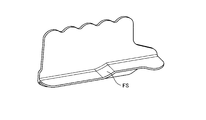
- FIG. 2 is a side view showing an example of a material obtained by processing of the material processing system.
- FIG. 3 is a side view showing an example of a material obtained by processing of the material processing system.
- FIG. 4 is a side view showing an example of a material obtained by processing of the material processing system.
- FIG. 5 is a side view showing an example of a material obtained by processing of the material processing system.
- FIG. 6 is a side view showing an example of a material obtained by processing of the material processing system.
- FIG. 7 is a side view showing an example of a material obtained by processing of the material processing system.
- FIG. 1 is a schematic block diagram showing an example of a material processing system including an embodiment of the present invention.
- FIG. 2 is a side view showing an example of a material obtained by processing of the material processing system.
- FIG. 3 is a side view showing an example of a material obtained
- FIG. 8 is a side view showing an example of a material obtained by processing of the material processing system.
- FIG. 9 is a side view showing an example of a material obtained by processing of the material processing system.
- FIG. 10 is a side view showing an example of the material obtained by the processing of the material processing system.
- FIG. 11 is a cross-sectional view showing an example of the curved surface portion.
- FIG. 12 is a cross-sectional view showing an example of the tapered portion.
- FIG. 13 is a cross-sectional view showing an example of the stepped portion.
- FIG. 14 is a cross-sectional view showing an example of the step portion.
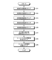
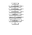
- FIG. 15 is a flowchart showing an example of the flow of the method of determining the material shape.
- FIG. 15 is a flowchart showing an example of the flow of the method of determining the material shape.
- FIG. 16 is a flowchart showing an example of the detailed flow of the flange classification step.
- FIG. 17 is a flowchart showing an example of a detailed flow of the grip setting step.
- FIG. 18 is a flowchart showing an example of the detailed flow of the material shape calculation step.
- FIG. 19 is a side view showing an example of the material determined by the method of determining the material shape.
- FIG. 20 is a side view showing an example of the material determined by the method of determining the material shape.
- FIG. 21 is a side view showing an example of the material determined by the method of determining the material shape.
- FIG. 22 is a side view showing an example of the material determined by the method of determining the material shape.
- FIG. 23 is a side view showing an example of the material determined by the method of determining the material shape.
- FIG. 24 is a side view showing an example of the material determined by the method of determining the material shape.
- FIG. 25 is a side view showing an example of the material determined by the method of determining the material shape.
- FIG. 26 is a side view showing an example of the material determined by the method of determining the material shape.
- FIG. 27 is a side view showing an example of the material determined by the method of determining the material shape.
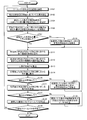
- FIG. 28 is a flowchart illustrating an example of a flow of a method of generating a numerical control program.
- FIG. 29 is a flowchart showing an example of the detailed flow of the element creating step.
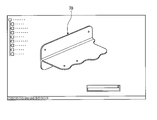
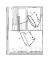
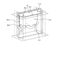
- FIG. 30 is a perspective view showing a material design model which is an example of the material shape.
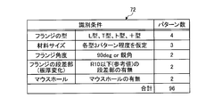
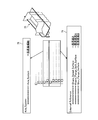
- FIG. 31 is a diagram showing an example of identification conditions of the material design model.
- FIG. 32 is a cross-sectional view showing an example of a 90 degree flange angle.
- FIG. 33 is a cross-sectional view showing an example of an acute flange angle.
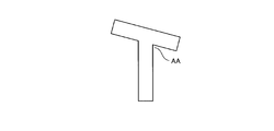
- FIG. 34 is a perspective view showing an example of the stepped portion in the flange.
- FIG. 35 is a perspective view showing an example of a mouse hole.
- FIG. 36 is an example of the existing material design model, and is a perspective view showing a similar material design model closest to the material shape.
- FIG. 37 is a flowchart showing an example of a detailed flow of the material element identification step.
- FIG. 38 is a flow chart showing an example of a detailed flow of automatically identifying an element of a material design model.
- FIG. 39 is a diagram showing an example of automatic identification when automatic identification is made from model element names.
- FIG. 40 is a diagram showing an example of reference element selection in the case of semi-automatic identification from reference element selection.
- FIG. 41 is a diagram showing an example of a material design model.
- FIG. 42 is a diagram showing an example of the element division method in the material design model.
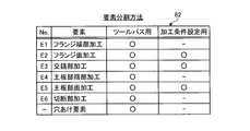
- FIG. 43 is a diagram showing an example of processing condition setting elements.
- FIG. 44 is a diagram showing an example of a tool path creation element.
- FIG. 45 is a flowchart showing an example of a detailed flow of the tool path creation step.
- FIG. 46 is a diagram showing an example of the stable area of the tool.
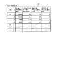
- FIG. 47 is a view showing a roughing tool condition which is an example of a combination of the spindle rotational speed of the tool and the feed amount per blade in roughing.
- FIG. 48 is a view showing a finishing tool condition which is an example of a combination of a spindle rotational speed of a tool and a feed amount per blade at the time of finishing.
- FIG. 49 is a view showing an example of the order of processing of the main plate material portion.
- FIG. 50 is a view showing an example of the processing order of the flange material portion.
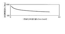
- FIG. 51 is a diagram showing an example of the relationship between the feed amount per blade and the specific cutting resistance.
- FIG. 52 is a diagram showing an example of calculation of processing conditions.
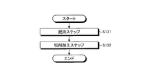
- FIG. 53 is a flowchart showing an example of the flow of the processing method.
- FIG. 54 is a side view showing an example of the gripping step.
- FIG. 55 is a side view showing an example of the gripping step.
- FIG. 56 is a side view showing an example of the gripping step.
- FIG. 57 is a side view showing an example of the gripping step.
- FIG. 58 is a side view showing an example of the gripping step.
- FIG. 59 is a flow chart showing an example of the details of the flow of the cutting step.
- FIG. 60 is a flowchart showing another example of the details of the flow of the cutting step.
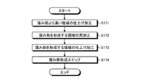
- FIG. 61 is a flowchart showing an example of details of the flow of the processing method including the drilling step.
- FIG. 62 is a diagram showing an example of the order of processing of the main plate material portion including the drilling portion.
- FIG. 63 is a diagram showing an example of the order of processing of the flange material portion including the drilling portion.
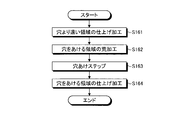
- FIG. 64 is a flow chart showing an example of details of the flow of the processing method including the depression portion forming step.
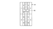
- FIG. 65 is a diagram showing an example of the order of processing of the portion including the depression portion forming portion.
- FIG. 1 is a schematic block diagram showing a material processing system 10 which is an example of a material processing system including an embodiment of the present invention.
- the material processing system 10 includes a material shape determination system 11, a numerical control program generation system 12, and a machining device 13.
- the material shape determination system 11 includes a control unit 11c.
- Control unit 11 c includes a storage unit and a processing unit.
- the storage unit includes, for example, storage devices such as a RAM, a ROM, and a flash memory, and stores software programs processed by the processing unit, data to be referred to by the software programs, and the like.
- the storage unit stores a material shape determination program 15 for causing the processing unit to execute the material shape determination method.
- the storage unit also functions as a storage area in which the processing unit temporarily stores processing results and the like.
- the processing unit reads out the software program and the like from the storage unit and processes the software program and the like to exhibit the function according to the contents of the software program.
- the processing unit executes the method of determining the material shape by reading and processing the material shape determination program 15 stored in the storage unit.
- the material shape determination system 11 is exemplified by a computer.
- the material shape determination program 15 is exemplified by CAD (Computer Aided Design) and a macro function incorporated in CAD.
- CAD Computer Aided Design
- the macro function incorporated in CAD is exemplified by the macro function of CATIA (registered trademark, Computer graphics Aided Three dimensional Interactive Application).
- the numerical control program generation system 12 includes a control unit 12 c.
- Control unit 12 c includes a storage unit and a processing unit.
- the storage unit includes, for example, storage devices such as a RAM, a ROM, and a flash memory, and stores software programs processed by the processing unit, data to be referred to by the software programs, and the like.
- the storage unit stores a numerical control program generation program 16 for causing the processing unit to execute the numerical control program generation method.
- the storage unit also functions as a storage area in which the processing unit temporarily stores processing results and the like.
- the processing unit reads out the software program and the like from the storage unit and processes the software program and the like to exhibit the function according to the contents of the software program.
- the processing unit executes the numerical control program generation method by reading out and processing the numerical control program generation program 16 stored in the storage unit, and the numerical control program (Numerical Control Program, NC Program) 19 is generated.
- the numerical control program generation system 12 is exemplified by a computer.
- the numerical control program generation program 16 includes a computer aided design program 17 and a computer aided manufacturing program 18.
- the computer aided design program 17 is exemplified by CAD (Computer Aided Design) and macro functions incorporated in CAD.
- the macro function incorporated in CAD is exemplified by the macro function of CATIA (registered trademark, Computer graphics Aided Three dimensional Interactive Application).
- the computer aided manufacturing program 18 is exemplified by CAM (Computer Aided Manufacturing).
- the numerical control program 19 is a program for controlling a machining operation of machining performed on a material.
- the control unit 12 c is not limited to an integral one, and has, for example, a first control unit that stores and processes the computer aided design program 17 and a second control unit that stores and processes the computer aided manufacturing program 18. May be That is, the generation program 16 of the numerical control program may be separately stored and executed across a plurality of control units.
- the machining device 13 includes a control unit 13c.
- Control unit 13 c includes a storage unit and a processing unit.
- the storage unit includes, for example, storage devices such as a RAM, a ROM, and a flash memory, and stores software programs processed by the processing unit, data to be referred to by the software programs, and the like.
- the storage unit stores a numerical control program 19 for causing the processing unit to execute a processing method, which is a machining processing operation performed on a material.
- the storage unit also functions as a storage area in which the processing unit temporarily stores processing results and the like.
- the processing unit reads out the software program and the like from the storage unit and processes the software program and the like to exhibit the function according to the contents of the software program.
- the processing unit reads out and processes the numerical control program 19 stored in the storage unit to execute the processing method to process the material.
- the machining device 13 is exemplified by a cutting device.
- FIG. 2 is a side view showing a material 20 which is an example of a material obtained by the processing of the material processing system 10.
- the material 20 has a main plate portion 20w as shown in FIG.
- the main plate portion 20 w is a plate-like portion which is formed extending in the axial direction A and is a portion including a plane element including a straight line of the distance between the longest two points in the material 20.
- the main plate portion 20 w is also referred to as a web because it has a widely-spread shape.
- the height in the plane along the largest surface element that is, the height in the direction orthogonal to the axial direction A is h w .
- the length in the plane along the largest surface element ie, the length in the direction along the axial direction A, is l w .
- the direction of thickness perpendicular to the maximum surface element is a t w.
- the height of the entire material 20, that is, the size of the entire material 20 along the direction of the height of the main plate portion 20w is h.
- the height h of the entire material 20 is equal to the height h w of the main plate portion 20w.
- the length of the entire material 20, that is, the size of the entire material 20 along the direction of the length of the main plate portion 20w is l.
- the entire length l of the material 20 is equal to the length l w of the main plate portion 20w.
- the width of the entire material 20, that is, the size of the entire material 20 along the direction of the thickness of the main plate portion 20w is w. In the case of the material 20, the width w of the entire material 20 is equal to the thickness t w of the main plate portion 20w.
- Material 20 does not have a flange.
- the material 20 is referred to as type I because the shape of the side surface viewed from the direction orthogonal to the axial direction A is similar to the letter I of the alphabet.
- the type I material exemplified as the material 20 is a shape that is a reference of the material obtained by the processing of the material processing system 10.
- the surface element including the straight line of the distance between the longest two points in the material is referred to as the largest surface element.
- the portion which is plate-shaped and extends along the axial direction and which includes the largest surface element in the material is referred to as a main plate portion.
- the height in the plane along the largest surface element, that is, the height in the direction orthogonal to the axial direction is referred to as the height of the main plate portion.
- the length in the plane along the largest surface element, that is, the length in the axial direction is referred to as the length of the main plate portion.
- the thickness in the direction orthogonal to the largest surface element is referred to as the thickness of the main plate portion.
- the size of the entire material along the direction of the height of the main plate is referred to as the height of the entire material.
- the size of the entire material along the direction of the length of the main plate is referred to as the total length of the material.
- the size of the entire material along the direction of the thickness of the main plate portion is referred to as the width of the entire material.
- the main plate portion is also referred to as a web because it has a widely extending shape.
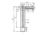
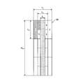
- FIG. 3 is a side view showing a material 22 which is an example of a material obtained by the processing of the material processing system 10.
- the material 22 has a main plate portion 22w, a flange 22f, and an intersecting portion 22m, as shown in FIG.
- the axial direction of the material 22 is in the direction perpendicular to the paper surface of FIG.
- the flange 22 f is formed to extend in the axial direction and is provided to extend from the main plate portion 22 w in a direction intersecting with the largest surface element.
- the crossing portion 22m is a portion where the main plate portion 22w and the flange 22f intersect, and includes a portion having a circular arc shape in a side view orthogonal to the axial direction.
- the height of the main plate portion 22w, the length of the main plate portion 22w, and the plate thickness of the main plate portion 22w in the material 22 are respectively given the same reference numerals as the material 20, and are h w , l w and t w .
- the length l w of the main plate portion 22 w is omitted in FIG.
- the height of the flange 22f which is the distance extending along the surface direction of the flange 22f and along the direction orthogonal to the axial direction, that is, the distance from the main plate 22w to the tip of the flange 22f is h f .
- the length of the flange 22f which is a distance extending along the surface direction of the flange 22f and along the axial direction, is l f . Since l f corresponds to the length l of the main plate portion 22 w and is generally common, it is omitted in FIG.
- the thickness of the flange 22 f which is a distance along the direction orthogonal to the surface direction of the flange 22 f , is t f .
- the flange 22 f is provided at an angle between the main plate portion 22 w and a predetermined surface.
- the angle between the predetermined surfaces formed between the flange 22f and the main plate portion 22w is referred to as the flange angle of the flange 22f.
- the flange 22 f is provided orthogonal to the main plate portion 22 w. That is, the flange angle of the flange 22f is 90 degrees. Further, the flange 22 f is provided on one surface side of the main plate portion 22 w, specifically, on the right side of the paper surface of FIG. 3.
- the flange 22f is provided at one end of the main plate portion 22w, specifically, the upper end of the paper surface of FIG. That is, the flange position which is the position in the main plate portion 22w of the flange 22f is an end.
- the flange position in the material 22 is a center position in the direction of the thickness t f of the flange 22 f in the main plate portion 22 w, and when the flange 22 f is at the end and the flange angle is 90 degrees, the flange The half of the plate thickness t f of the flange 22 f is subtracted from the height h w of the main plate portion 22 w with the end of the main plate portion 22 w on the side not having 22 f, that is, the lower end in the plane of FIG. It is calculated by
- the height h of the entire material 22 is equal to the height h w of the main plate portion 22 w .
- the length l of the entire material 22 is equal to the longer of the length l w of the main plate portion 22 w and the length l f of the flange 22 f .
- the width w of the entire material 22 is equal to the sum of half of the plate thickness t w of the main plate portion 22 w and the height h f of the flange 22 f .
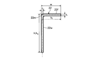
- the material 22 has a flange 22f having a flange angle of 90 degrees on one surface side of one end of the main plate portion 22w. Therefore, the material 22 is referred to as an L-shape because the shape of the side surface viewed from the direction orthogonal to the axial direction is similar to L of the alphabet. Further, the flange 22 f is referred to as an L-shaped flange.
- a portion extending in the axial direction and extending in the direction intersecting with the largest surface element from the main plate portion is a flange It is called.
- a portion including a portion where the main plate portion and the flange intersect and which includes a portion having a circular arc shape in a side view orthogonal to the axial direction is referred to as an intersecting portion.
- the distance extending along the surface direction of the flange and along the direction orthogonal to the axial direction that is, the distance from the main plate to the tip of the flange is referred to as the height of the flange.
- the distance extending along the surface direction of the flange and along the axial direction is referred to as the flange length.
- the distance along the direction orthogonal to the surface direction of the flange is referred to as the flange thickness.
- the angle between a predetermined surface formed between the flange and the main plate portion is referred to as a flange angle.
- the central position of the main plate in the direction of the thickness of the flange is referred to as the flange position.
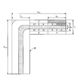
- FIG. 4 is a side view showing a material 24 which is an example of the material obtained by the processing of the material processing system 10.
- the material 24 has a main plate portion 24w, a flange 24f, and an intersecting portion 24m, as shown in FIG.
- the axial direction of the material 24 is in the direction perpendicular to the paper surface of FIG.
- the height of the main plate portion 24w, the length of the main plate portion 24w, and the plate thickness of the main plate portion 24w in the material 24 are the same as those of the material 20 and the material 22, respectively, and h w , l w and t w is there.
- the height of the flange 24f, the length of the flange 24f, and the thickness of the flange 24f in the material 24 are respectively given the same reference numerals as the material 22, and are h f , l f and t f .
- the length l w of the main plate portion 24 w and the length l f of the flange 24 f are omitted in FIG. 4.
- the flange angle of the flange 24 f in the material 24 is (90 + ⁇ ) degrees. However, ⁇ is a value greater than 0 degrees and less than 90 degrees. Further, the flange 24f is provided on one surface side of the main plate portion 24w, specifically, on the right side of the paper surface of FIG. The flange 24f is provided at any one end of the main plate portion 24w, specifically, the upper end of the paper surface of FIG. That is, the flange position of the flange 24f is determined from the height h w of the main plate portion 24w with the end of the main plate portion 24w on the side not having the flange 24f, that is, the lower end of the paper surface of FIG. The value is calculated by subtracting the product of cos ⁇ corresponding to half of the plate thickness t f of 24 f and the sine component of the flange angle.
- the height h of the entire material 24 is the height h w of the main plate portion 24 w and sin ⁇ corresponding to the height h f of the flange 24 f and the cosine of the flange angle It is equal to the product of and the sum of Further, the length l of the entire material 24 is equal to the longer of the length l w of the main plate portion 24 w and the length l f of the flange 24 f .
- the width w of the entire material 24 is half the plate thickness t w of the main plate portion 24 w, the product h f cos ⁇ of cos ⁇ corresponding to the height h f of the flange 24 f and the sine component of the flange angle, and the flange 24 f It is equal to the sum of half the plate thickness t f and the product of sin ⁇ corresponding to the cosine component of the flange angle.
- the material 24 is the one in which the flange angle is changed from 90 degrees to (90 + ⁇ ) degrees with respect to the material 22 and is classified into the L-shape similarly to the material 22. Also, the flange 24 f is classified into an L-shaped flange.
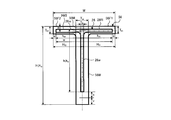
- FIG. 5 is a side view showing a material 26 which is an example of a material obtained by processing of the material processing system 10.
- the material 26 has a main plate portion 26w, a flange 26f1, a flange 26f2, and an intersecting portion 26m.
- the axial direction of the material 26 is in the direction perpendicular to the paper surface of FIG.
- the height of the main plate portion 26w, the length of the main plate portion 26w, and the plate thickness of the main plate portion 26w in the material 26 are respectively given the same reference numerals as the material 20, the material 22 and the material 24; h w , l w and It is t w .
- the height of the flange 26f1, the length of the flange 26f1 and the thickness of the flange 26f1 in the material 26 are h f1 , l f1 and t f1 , respectively.
- the height of the flange 26 f 2, the length of the flange 26 f 2 and the thickness of the flange 26 f 2 in the material 26 are h f 2 , l f 2 and t f 2 respectively.
- the length l w of the main plate portion 26 w , the length l f 1 of the flange 26 f 1 and the length l f 2 of the flange 26 f 2 are omitted in FIG. 5.
- the flange angle of the flange 26f1 in the material 26 is 90 degrees. Further, the flange angle of the flange 26f2 in the material 26 is 90 degrees. Further, the flange 26f1 is provided on one surface side of the main plate portion 26w, specifically, on the right side of the paper surface of FIG. Further, the flange 26f2 is provided on the other surface side of the main plate portion 26w, specifically, on the left side of the paper surface of FIG. That is, when the flange 26f1 and the flange 26f2 are integrally considered in the material 26, the flange 26f1 and the flange 26f2 are provided on both sides of the main plate portion 26w.
- the flange 26f1 and the flange 26f2 are both provided at one end of the main plate portion 26w, specifically, the upper end of the paper surface of FIG. That is, the flange position of the flange 26f1 is the height h w of the main plate 26w with the end of the main plate 26w on the side not having the flange 26f1 and the flange 26f2, that is, the lower end in the drawing of FIG. From the above, a value obtained by subtracting one half of the plate thickness t f1 of the flange 26 f1 is calculated.
- the flange position of the flange 26f2 is the height h w of the main plate portion 26w with the end of the main plate portion 26w on the side not having the flange 26f1 and the flange 26f2, ie, the lower end in the drawing of FIG. From the above, a value obtained by subtracting half of the plate thickness t f2 of the flange 26 f 2 is calculated. When the plate thickness t f1 of the flange 26 f 1 and the plate thickness t f 2 of the flange 26 f 2 are equal, the flange position of the flange 26 f 1 and the flange position of the flange 26 f 2 become the same.
- the height h of the entire material 26 is equal to the height h w of the main plate portion 26 w .
- the length l of the entire material 26 is equal to the longest of the length l w of the main plate portion 26 w , the length l f1 of the flange 26 f 1 and the length l f 2 of the flange 26 f 2 .
- the entire width w of the material 26 is equal to the sum of the height h f1 of the flange 26 f 1 and the height h f 2 of the flange 26 f 2 .
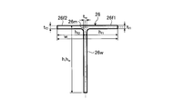
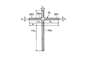
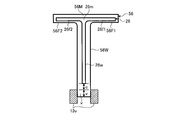
- the material 26 has a flange 26f1 and a flange 26f2 having a flange angle of 90 degrees on both sides of one end of the main plate portion 26w. Therefore, the material 26 is referred to as a T-shape because the shape of the side surface seen from the direction orthogonal to the axial direction is similar to the letter T.
- the flange 26f1 and the flange 26f2 are collectively referred to as a T-shaped flange.
- FIG. 6 is a side view showing a material 28 which is an example of the material obtained by the processing of the material processing system 10.
- the material 28 has a main plate portion 28w, a flange 28f1, a flange 28f2, and an intersecting portion 28m.
- the axial direction of the material 28 is in the direction perpendicular to the paper surface of FIG.
- the main plate portion 28w of the height in the material 28, the thickness of the length and the main plate portion 28w of the main plate portion 28w, respectively, material 20, material 22, are denoted by the same reference numerals as the material 24 and material 26, h w, l w and t w .
- the height of the flange 28f1 in the material 28, the length of the flange 28f1 and the thickness of the flange 28f1 are the same as those of the material 26, respectively, and are h f1 , l f1 and t f1 .
- the height of the flange 28f2 in the material 28, the length of the flange 28f2 and the thickness of the flange 28f2 are the same as those of the material 26, respectively, and are h f2 , l f2 and t f2 .
- the length l w of the main plate portion 28 w , the length l f 1 of the flange 28 f 1 and the length l f 2 of the flange 28 f 2 are omitted in FIG.
- the flange angle of the flange 28f1 in the material 28 is (90 + ⁇ 1) degrees. However, ⁇ 1 is a value greater than 0 degrees and less than 90 degrees.
- the flange angle of the flange 28f2 in the material 28 is (90- ⁇ 2) degrees. However, ⁇ 2 is a value greater than 0 degrees and less than 90 degrees.
- the flange 28f1 is provided on one surface side of the main plate portion 28w, specifically, on the right side of the paper surface of FIG.
- the flange 28f2 is provided on the other surface side of the main plate portion 28w, specifically, on the left side of the paper surface of FIG. That is, when the flange 28f1 and the flange 28f2 are integrally considered in the material 28, the flange 28f1 and the flange 28f2 are provided on both sides of the main plate portion 28w.
- the flange 28f1 and the flange 28f2 are both provided at one end of the main plate portion 28w, specifically, at the upper end of the paper surface of FIG. That is, the flange position of the flange 28f1 is the height h w of the main plate 28w with the end of the main plate 28w on the side not having the flange 28f1 and the flange 28f2, ie, the lower end in the drawing of FIG. From the above, a value obtained by subtracting the product of cos ⁇ 1 corresponding to a half of the plate thickness t f1 of the flange 28 f1 and the sine component of the flange angle is calculated.
- the flange position of the flange 28f2 is the height h w of the main plate 28w with the end of the main plate 28w on the side not having the flange 28f1 and the flange 28f2, that is, the lower end in the drawing of FIG. From the above, a value obtained by subtracting the product of cos ⁇ 2 corresponding to a half of the plate thickness t f2 of the flange 28 f 2 and the sine component of the flange angle is calculated.
- the parameter ⁇ 1 for determining the flange angle of the flange 28 f 1 is equal to the parameter ⁇ 2 for determining the flange angle of the flange 28 f 2
- the flange position of the flange 28f1 and the flange position of the flange 28f2 are the same.
- the height h of the entire material 28 corresponds to the height h w of the main plate portion 28 w , the height h f1 of the flange 28 f 1 and the cosine component of the flange angle It is equal to the product of and the sum of Further, the length l of the entire material 28 is equal to the longest of the length l w of the main plate portion 28 w , the length l f1 of the flange 28 f 1 and the length l f 2 of the flange 28 f 2 .
- the entire width w of the material 28 corresponds to the product of the height h f1 of the flange 28 f 1 and the product of cos ⁇ 1 corresponding to the sine component of the flange angle, the half of the plate thickness t f 1 of the flange 28 f 1 and the cosine component of the flange angle
- Product of sin ⁇ 1 product of height h f 2 of flange 28 f 2 and product of cos ⁇ 2 corresponding to sine component of flange angle
- product of sin ⁇ 2 corresponding to half of plate thickness t f 2 of flange 28 f 2 and cosine component of flange angle It is equal to the sum of and.
- the material 28 is obtained by changing the flange angle of the material 26 from 90 degrees to (90 + ⁇ 1) degrees and (90 ⁇ 2) degrees, respectively, and is classified into a T-shape similarly to the material 26. Further, the flange 28f1 and the flange 28f2 are collectively classified as a T-shaped flange.
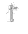
- FIG. 7 is a side view showing a material 32 which is an example of the material obtained by the processing of the material processing system 10.
- the material 32 has a main plate portion 32w, a flange 32f, and crossing portions 32m.
- the axial direction of the material 32 is in the direction perpendicular to the paper surface of FIG.
- the height of the main plate portion 32w, the length of the main plate portion 32w, and the plate thickness of the main plate portion 32w in the material 32 are given the same reference numerals as the material 20, the material 22, the material 24, the material 26 and the material 28, respectively h w , l w and t w .
- the height of the flange 32f, the length of the flange 32f, and the thickness of the flange 32f in the material 32 are the same as those of the material 22 and the material 24, respectively, and are h f , l f and t f .
- the length l w of the main plate portion 32 w and the length l f of the flange 32 f are omitted in FIG. 7.
- the flange angle of the flange 32f in the material 32 is 90 degrees. Further, the flange 32f is provided on one surface side of the main plate portion 32w, specifically, on the right side of the paper surface of FIG. The flange 32 f is provided at a position other than the end of the main plate portion 32 w. That is, the flange position of the flange 32f is smaller than the height h w of the main plate 32w with the end of the main plate 32w far from the flange 32f, that is, the lower end in the plane of FIG. It is calculated.
- the height h of the entire material 32 is equal to the height h w of the main plate portion 32 w .
- the length l of the entire material 32 is equal to the longer one of the length l w of the main plate portion 32 w and the length l f of the flange 32 f .
- the width w of the entire material 32 is equal to the sum of half of the plate thickness t w of the main plate portion 32 w and the height h f of the flange 32 f .
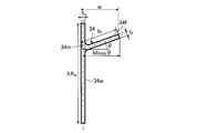
- the material 32 has a flange 32f having a flange angle of 90 degrees on one surface side other than the end of the main plate portion 32w. Therefore, the material 32 is referred to as a letter shape because the shape of the side surface seen from the direction orthogonal to the axial direction is similar to that of Japanese katakana.
- the flange 32f is referred to as a "t-shaped flange”.
- FIG. 8 is a side view showing a material 34 which is an example of the material obtained by the processing of the material processing system 10.
- the material 34 has, as shown in FIG. 8, a main plate portion 34w, a flange 34f, and an intersecting portion 34m.
- the axial direction of the material 34 is in the direction perpendicular to the paper surface of FIG.
- the height of the main plate portion 34w, the length of the main plate portion 34w and the plate thickness of the main plate portion 34w in the material 34 are given the same reference numerals as the material 20, the material 22, the material 24, the material 26, the material 28 and the material 32, respectively H w , l w and t w .
- the height of flange 34f in material 34, the length of flange 34f and the plate thickness of flange 34f are respectively assigned the same reference numerals as material 22, material 24 and material 32, h f , l f and t f is there.
- the length l w of the main plate portion 34 w and the length l f of the flange 34 f are omitted in FIG. 8.
- the flange angle of the flange 34f in the material 34 is (90 + ⁇ ) degrees. Further, the flange 34f is provided on one surface side of the main plate portion 34w, specifically, on the right side of the paper surface of FIG. The flange 34f is provided at a position other than the end of the main plate portion 34w. That is, with respect to the flange position of the flange 34f, the main plate portion 34w takes the end of the main plate portion 34w on the side where the angle formed by the flange 34f with the main plate portion 34w becomes an obtuse angle, that is, the lower end of the sheet of FIG. It is calculated with a value smaller than the height h w of .
- the height h of the entire material 34 is the height h w of the main plate portion 34 w and the height h f of the flange 34 f at the flange position and the cosine component of the flange angle
- the product of the corresponding sin ⁇ and the product of the half of the plate thickness t f of the flange 34 f and the product of cos ⁇ corresponding to the sine component of the flange angle are equal to the larger one.
- the height h of the entire material 34 is equal to the height h w of the main plate portion 34w
- the flange 34f is the main plate portion 34w.
- the product of sin ⁇ corresponding to the height h f of the flange 34 f and the cosine component of the flange angle at the flange position and half the plate thickness t f of the flange 34 f and the flange angle It is equal to the product of cos ⁇ corresponding to the sine component of.
- the entire length l of the material 34 is equal to the longer of the length l w of the main plate portion 34 w and the length l f of the flange 34 f .
- the width w of the entire material 34 is half the plate thickness t w of the main plate portion 34 w, the product h f cos ⁇ of cos ⁇ corresponding to the height h f of the flange 34 f and the sine component of the flange angle It is equal to the sum of half the plate thickness t f and the product of sin ⁇ corresponding to the cosine component of the flange angle.
- the material 34 is obtained by changing the flange angle from 90 degrees to (90 + ⁇ ) degrees with respect to the material 32, and is classified into a gong like the material 32. Further, the flange 34f is classified into a toe-shaped flange.
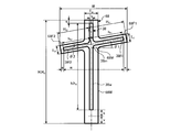
- FIG. 9 is a side view showing a material 36 which is an example of a material obtained by the processing of the material processing system 10.
- the material 36 has, as shown in FIG. 9, a main plate portion 36w, a flange 36f1, a flange 36f2, and an intersecting portion 36m.
- the axial direction of the material 36 is in the direction perpendicular to the paper surface of FIG.
- the height of the main plate portion 36w, the length of the main plate portion 36w, and the plate thickness of the main plate portion 36w in the material 36 are the same as those of the material 20, material 22, material 24, material 26, material 28, material 32, and material 34, respectively. And are h w , l w and t w .
- the height of the flange 36f1 in the material 36, the length and thickness of the flange 36f1 of the flange 36f1, respectively, are denoted by the same reference numerals as the material 26 and material 28 are h f1, l f1 and t f1.
- the height of the flange 36f2, the length of the flange 36f2 and the thickness of the flange 36f2 of the material 36 are the same as those of the material 26 and the material 28, respectively, and are h f2 , l f2 and t f2 .
- the length l w of the main plate portion 36 w , the length l f 1 of the flange 36 f 1 and the length l f 2 of the flange 36 f 2 are omitted in FIG. 9.
- the flange angle of the flange 36f1 in the material 36 is 90 degrees.
- the flange angle of the flange 36f2 in the material 36 is 90 degrees.
- the flange 36f1 is provided on one surface side of the main plate portion 36w, specifically, on the right side of the paper surface of FIG.
- the flange 36f2 is provided on the other surface side of the main plate portion 36w, specifically, on the left side of the paper surface of FIG. That is, when the flange 36f1 and the flange 36f2 are integrally considered in the material 36, the flange 36f1 and the flange 36f2 are provided on both sides of the main plate portion 36w.
- the flange 36f1 and the flange 36f2 are both provided at positions other than the end of the main plate portion 36w. That is, the flange positions of the flanges 36f1 and 36f2 are the same as the flanges 36f1 and 36f2 except for the end of the main plate 36w remote from the flange 36f2, that is, the lower end of the sheet of FIG. It is calculated with a value smaller than the height h w .
- the height h of the entire material 36 is equal to the height h w of the main plate portion 36 w .
- the length l of the entire material 36 is equal to the longest of the length l w of the main plate portion 36 w , the length l f1 of the flange 36 f 1 and the length l f 2 of the flange 36 f 2
- the width w of the entire material 36 is equal to the sum of the height h f1 of the flange 36 f 1 and the height h f 2 of the flange 36 f 2 .
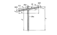
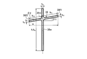
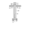
- the material 36 has a flange 36f1 and a flange 36f2 having a flange angle of 90 degrees on both sides of the main plate 36w except for the end. Therefore, the material 36 is referred to as a + type because the shape of the side surface viewed from the direction orthogonal to the axial direction is similar to the + of the operation symbol. Further, the flange 36f1 and the flange 36f2 are collectively referred to as a + type flange.
- FIG. 10 is a side view showing a material 38 which is an example of the material obtained by the processing of the material processing system 10.
- the material 38 has, as shown in FIG. 10, a main plate portion 38w, a flange 38f1, a flange 38f2, and an intersecting portion 38m.
- the axial direction of the material 38 is in the direction perpendicular to the paper surface of FIG.
- the height of the main plate portion 38w, the length of the main plate portion 38w and the plate thickness of the main plate portion 38w in the material 38 are respectively the material 20, the material 22, the material 24, the material 26, the material 28, the material 32, the material 32, the material 34 and the material 36 And h w , l w and t w .
- the height of the flange 38f1 in the material 38, the length of the flange 38f1 and the thickness of the flange 38f1 are the same as those of the material 26, the material 28 and the material 36 respectively, and h f1 , l f1 and t f1 is there.
- the height of the flange 38f2 in the material 38, the length of the flange 38f2 and the thickness of the flange 38f2 are the same as those of the material 26, the material 28 and the material 36 respectively, with h f2 , l f2 and t f2 is there.
- the length l w of the main plate portion 38 w , the length l f 1 of the flange 38 f 1 and the length l f 2 of the flange 38 f 2 are omitted in FIG. 10.
- the flange angle of the flange 38f1 in the material 38 is (90 + ⁇ 1) degrees. However, ⁇ 1 is a value greater than 0 degrees and less than 90 degrees.
- the flange angle of the flange 38f2 in the material 38 is (90- ⁇ 2) degrees. However, ⁇ 2 is a value greater than 0 degrees and less than 90 degrees.
- the flange 38f1 is provided on one surface side of the main plate portion 38w, specifically, on the right side of the paper surface of FIG. Further, the flange 38f2 is provided on the other surface side of the main plate portion 38w, specifically, on the left side of the paper surface of FIG. That is, when the flange 38f1 and the flange 38f2 are integrally considered in the material 38, the flange 38f1 and the flange 38f2 are provided on both sides of the main plate portion 38w.
- the flange 38f1 and the flange 38f2 are both provided at positions other than the end of the main plate portion 38w. That is, the flange positions of the flange 38f1 and the flange 38f2 are the same as those of the main plate 38w with the end of the main plate 38w remote from the flange 38f1 and the flange 38f2, that is, the lower end in the drawing of FIG. It is calculated with a value smaller than the height h w .
- the height h of the material 38 as a whole is such that the flange 38f1 does not protrude one end of the main plate 38w in the height direction, and the flange 38f2 is the main plate When the other end of 38 w is not protruded in the height direction, it is equal to the height h w of the main plate portion 38 w .
- the flange 38f1 protrudes one end of the main plate 38w in the height direction
- the flange 38f2 protrudes the other end of the main plate 38w in the height
- the flange position from the end of the main plate portion 38 w corresponds to the height h f 1 of the flange 38 f 1 and sin ⁇ 1 corresponding to the cosine component of the flange angle It is equal to the product plus the product of half of the plate thickness t f1 of the flange 38 f 1 and cos ⁇ 1 corresponding to the sine component of the flange angle.
- the height h of the material 38 as a whole is such that the flange 38f1 does not project one end of the main plate portion 38w in the height direction, and the flange 38f2 does not protrude the other end of the main plate portion 38w in the height direction
- the product of cos ⁇ 2 corresponding to half of the plate thickness t f 2 of the flange 38 f 2 and the sine component of the flange angle.
- the main plate portion 38w is a portion including a plane element including the straight line of the distance between the longest two points, the flange 38f1 protrudes one end of the main plate portion 38w in the height direction, and the flange If 38f2 protrudes in the height direction from the other end of the main plate 38w, it does not exist.
- the length l of the entire material 38 is equal to the longest of the length l w of the main plate portion 38 w , the length l f1 of the flange 38 f 1 and the length l f 2 of the flange 38 f 2 .
- the entire width w of the material 38 corresponds to the product of the height h f1 of the flange 38 f 1 and the product of cos ⁇ 1 corresponding to the sine component of the flange angle, the half of the plate thickness t f 1 of the flange 38 f 1 and the cosine component of the flange angle
- Product of sin ⁇ 1 product of height h f2 of flange 38 f 2 and product of cos ⁇ 2 corresponding to sine component of flange angle
- product of sin ⁇ 2 corresponding to half of plate thickness t f 2 of flange 38 f 2 and cosine component of flange angle It is equal to the sum of and.
- the material 38 is obtained by changing the flange angle of the material 36 from 90 degrees to (90 + ⁇ 1) degrees and (90 ⁇ 2) degrees, respectively, and is classified into the + type in the same manner as the material 36. Further, the flange 38f1 and the flange 38f2 are collectively classified as a + type flange.
- the material 20, the material 22, the material 24, the material 26, the material 28, the material 32, the material 34, the material 36 as an example of the material obtained by processing of the material processing system 10 using FIGS.
- the material 38 has been described as an example, but the material obtained by the processing of the material processing system 10 is not limited to this, and is formed like a plate and extending along the axial direction, and Also included is any material having a main plate including a face element and at least one or more flanges extending axially and extending from the main plate in a direction intersecting the largest face element.
- FIG. 11 is a cross-sectional view showing a curved surface portion 41 which is an example of the curved surface portion.
- FIG. 12 is a cross-sectional view showing a taper portion 42 which is an example of the taper portion.
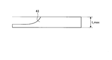
- FIG. 13 is a cross-sectional view showing a stepped portion 43 which is an example of the stepped portion.
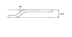
- FIG. 14 is a cross-sectional view showing a stepped portion 44 which is an example of the stepped portion.
- the curved surface portion 41 is a portion where a curve is formed in the plate exemplified by the main plate portion and the flange as shown in FIG. In the curved surface portion 41, the difference between the highest point and the lowest point of the curved portion is t_max. As shown in FIG.
- the tapered portion 42 is a portion in which a region in which the plate thickness gradually changes is formed on the plate exemplified by the main plate portion and the flange.
- the plate thickness of the thickest portion is t_max.
- the stepped portion 43 is a portion in which a region where the plate thickness suddenly changes is formed on the plate exemplified by the main plate portion and the flange.
- the thickness of the thickest portion of the step portion 43 is t_max.
- the step portion 44 is a portion where a sharp bend is formed in the plate exemplified by the main plate portion and the flange.
- the difference between the highest point and the lowest point of the portion where the sharp bending is formed is t_max.
- t_max in the curved surface portion 41 shown in FIG. 11, the tapered portion 42 shown in FIG. 12, the step 43 shown in FIG. 13, and the step 44 shown in FIG. 14 will be referred to as the thickness of the thickest portion.
- the material obtained by the processing of the material processing system 10 includes the curved surface portion 41 shown in FIG. 11, the tapered portion 42 shown in FIG. 12, the step 43 shown in FIG. 13, and the step 44 shown in FIG. Any one or more may be included.
- the material obtained by the processing of the material processing system 10 may also include, for each surface, a change in height in the direction perpendicular to the surface.
- the materials obtained by the processing of the material processing system 10 mentioned above are suitably used for aircraft parts exemplified by stringers, shear ties, frames and the like.
- FIG. 15 is a flowchart showing an example of the flow of the method of determining the material shape.
- the material shape determination method is a processing method that is executed by the control unit 11 c reading out and processing the material shape determination program 15 in the material shape determination system 11.
- the method of determining the material shape will be described with reference to FIG.
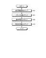
- the material shape determination method includes, as shown in FIG. 15, a material information acquisition step S12, a flange classification step S14, a grip portion setting step S16, and a material shape calculation step S18.
- the material information acquisition step S12, the flange classification step S14, the holding portion setting step S16, and the material shape calculation step S18 will be referred to simply as step S12, step S14, step S16 and step S18, respectively.
- control unit 11c acquires information on the shape of the material (step S12). Specifically, the control unit 11c acquires information of a design model of a three-dimensional design model created for a material by computer aided design software or the like exemplified by CAD (Computer Aided Design).
- CAD Computer Aided Design
- control unit 11c classifies the shape of the flange based on the acquired information on the shape of the material (step S14). Specifically, for example, the control unit 11 c classifies the shape of the flange into the above-described L-shaped flange, T-shaped flange, toe-shaped flange, and + -shaped flange. If there is no flange, the material is automatically classified as I-type in step S14.
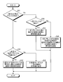
- FIG. 16 is a flowchart showing an example of the detailed flow of the flange classification step S14.
- the flange position discrimination step S21 the flange installation surface side discrimination step S22, the L type flange classification step S23, the T type flange classification step S24, and the flange installation surface side discrimination Step S26, g-type flange classification step S27, and + -type flange classification step S28.
- flange position discrimination step S21 flange installation surface side discrimination step S22, L type flange classification step S23, T type flange classification step S24, flange installation surface side discrimination step S26, g type flange classification step S27, + type flange
- the classification step S28 is appropriately referred to simply as step S21, step S22, step S23, step S24, step S26, step S27 and step S28, respectively.
- the control unit 11c determines whether the flange is at the end (step S21). When the flange to be classified is at the end (Yes in step S21), the control unit 11c determines whether the flange to be classified is provided only on one side of the main plate in the thickness direction of the main plate. It discriminates (step S22). Here, in step S22, the control unit 11c determines that the flange is provided on both sides when the flange position is within a predetermined distance and the flange exists on the opposite side of the classification target flange. Treat these flanges including the flanges to be classified as one flange.
- step S22 when the flange position approaches within a predetermined distance and there is no flange on the opposite side of the classification target flange, the control unit 11c assumes that the classification target flange is provided on only one side. Determine and process.
- the control unit 11c is a flange to be classified. Are classified as L-shaped flanges (step S23). If the flange to be classified is at the end (Yes at step S21) and if the flanges to be classified are provided at both sides (No at step S22), the control unit 11c determines the flanges to be classified. It classifies into T type flange (step S24).
- Step S26 is the same process as step S22.
- the control unit 11c determines the flange to be classified. Are classified as to-shaped flanges (step S27). If the flange to be classified does not exist at the end (No at Step S21) and the flanges to be classified are provided at both sides (No at Step S26), the control unit 11c determines the flanges to be classified. It classifies into + type flange (step S28).
- the control unit 11 c ends the flange classification step S ⁇ b> 14 when classification of the flange shapes is finished for all the flanges included in the acquired material shape information.
- T-type flanges may be regarded as two L-type flanges
- + type flanges may be regarded as two two-type flanges
- only L-type flanges and two-type flanges may be classified. May be classified.
- control unit 11c sets a gripping unit to be gripped in processing the material, based on the acquired information on the shape of the material and the classification information on the flange at the flange classification step S14 (step S16). For example, the control unit 11 c sets the gripping unit at any one end of the main plate. If the material is classified as I-type in step S14, a gripping portion is automatically set at one end of the main plate portion in step S16.
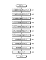
- FIG. 17 is a flowchart showing an example of a detailed flow of the gripping unit setting step S16.
- the holding unit setting step S16 includes a first flange information determining step S31, a second flange information determining step S32, a first holding unit setting step S33, and a second holding unit setting step S34.
- the third flange information determining step S36, the third holding unit setting step S37, and the fourth holding unit setting step S38 are included.
- step S31 the first flange information discrimination step S31, the second flange information discrimination step S32, the first gripping portion setting step S33, the second gripping portion setting step S34, the third flange information discriminating step S36, the third gripping portion setting step
- step S37 and the fourth holding portion setting step S38 will be referred to simply as step S31, step S32, step S33, step S34, step S36, step S37 and step S38, respectively, as appropriate.
- the control portion 11c determines whether or not the flange classification information in the flange classification step S14 has an L-shaped flange or a T-shaped flange (step S31). If there is an L-shaped flange or a T-shaped flange (Yes in step S31), the control unit 11c determines whether the L-shaped flange or the T-shaped flange is provided only at one end of the main plate (step) S32). When there is no L-shaped flange or T-shaped flange (No in step S31), the control unit 11c determines whether or not there is a + -shaped flange (step S36).
- step S31 In the case where there is an L-shaped flange or a T-shaped flange (Yes in step S31) and the L-shaped flange or the T-shaped flange is provided only at one end of the main plate portion (in step S32). Yes) Set the grip on the end of the main plate that does not have an L-shaped flange or T-shaped flange (step S33), and end the grip setting step S16.
- step S31 When there is an L-shaped flange or a T-shaped flange (Yes in step S31), and the L-shaped flange or the T-shaped flange is provided on both ends of the main plate portion (No in step S32).
- step S34 it may be determined, based on the shape of the L-shaped flange or the T-shaped flange provided at each end, for example, at which end the gripping portion is to be set.
- step S31 If there is no L-shaped flange or T-shaped flange (No in step S31) and there is a positive-type flange (Yes in step S36), the control unit 11c is located at the end of the main plate remote from the positive-type flange.
- the gripping part is set (step S37), and the gripping part setting step S16 is ended.
- the controller 11c determines that the angle formed by the g-shaped flange with the main plate is a right angle or The grip portion is set at the end of the main plate portion at the obtuse angle (step S38), and the grip portion setting step S16 is ended.
- the control unit 11c selects a material necessary for processing the material based on the acquired information on the shape of the material, the classification information on the flange at the flange classification step S14, and the setting information on the holding unit at the holding unit setting step S16.
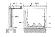
- the shape is calculated (step S18). Specifically, with respect to the shape of the material, the control unit 11 c has an extra thickness which is an outer peripheral machining allowance, a gripping portion for gripping, a material obtained by processing of the material processing system 10 and a gripping portion v.
- the shape of the material is determined by setting a cutting portion which is a portion for cutting a gap.
- FIG. 18 is a flowchart showing an example of the detailed flow of the material shape calculation step S18.
- Material shape calculation step S18 as shown in FIG. 18, main plate portion material height calculation step S41, main plate portion material length calculation step S42, main plate portion material plate thickness calculation step S43, and flange material height calculation step S45, flange material length calculation step S46, flange material plate thickness calculation step S47, flange material plate thickness correction step S48, material height calculation step S51, material length calculation step S52, material width calculation step And S53 and a correction step S55.
- the thickness calculation step S47, the flange material plate thickness correction step S48, the material height calculation step S51, the material length calculation step S52, the material width calculation step S53 and the correction step S55 are simply simply respectively performed as steps S41, S42 and S43.
- Step S45, step S46, step S47, step S48, step S51, step S52, step S53 and step S55 are simply simply respectively performed as steps S41, S42 and S43.
- the control unit 11c is included in the material, and in the main plate material portion before being processed into the main plate portion, the main plate portion material height which is a size along the height direction of the main plate portion It calculates (step S41). Specifically, the control unit 11 c calculates the height of the main plate material based on the height h w of the main plate, the size of the excess thickness, the height of the grip, and the height of the cut portion. For example, the control unit 11c calculates the height of the main plate material by the sum of the height h w of the main plate, the size of the excess thickness, the height of the grip, and the height of the cut portion.
- the control unit 11c calculates the main plate portion material length which is a size along the length direction of the main plate portion (step S42). Specifically, the control unit 11 c calculates the main plate portion material length based on the length l w of the main plate portion and the size of the excess thickness. For example, the control unit 11c sets the main plate portion material length to the length l w of the main plate portion, the excess thickness provided on one of the main plate portion in the length direction, and the excess thickness provided on the other of the main plate portion in the length direction. It is calculated by the sum of the meat, that is, the sum of the length l w of the main plate portion and twice the size of the extra meat.
- the control unit 11c calculates the main plate portion material plate thickness which is a size along the plate thickness direction of the main plate portion (step S43). Specifically, the control unit 11c calculates the main plate portion material plate thickness based on the main plate portion material height calculated in step S41, the height of the grip portion, and the parameter based on the material. For example, the control unit 11c calculates the main plate portion material plate thickness to a length equal to or greater than the product of the value obtained by subtracting the height of the grip portion from the main plate portion material height and the parameter based on the material.
- the parameter based on the material is a value previously determined according to the rigidity of the material, and for example, 1/5 is exemplified in the case of aluminum suitably used for aircraft parts.
- Steps S41, S42 and S43 are all processes for calculating the size of the main plate material portion.
- the processing is performed in the order of step S41, step S42 and step S43, but the present invention is not limited to this, and the processing may be performed in order of step S42, step S41 and step S43, The processing may be performed in the order of step S41, step S43 and step S42.
- step S43 is a process using the main-plate part raw material height calculated by step S41, it is performed after step S41.
- the control unit 11c calculates the flange material height which is a size along the height direction of the flange in the flange material portion before being processed into the flange, which is included in the material (step S45). Specifically, the control unit 11 c calculates the flange material height based on the height h f of the flange, the size of the excess thickness, and the flange angle. For example, the control unit 11c calculates the flange material height by the sum of the flange height h f and the product of cos ⁇ or the like corresponding to the size of the excess thickness and the sine component of the flange angle.
- the control unit 11c calculates a flange material length which is a size along the length direction of the flange in the flange material portion (step S46). Specifically, the control unit 11c calculates the flange material length based on the flange length l f and the size of the excess thickness. For example, the control unit 11c may set the flange material length to the flange length l f , the extra thickness provided on one side in the longitudinal direction of the flange, and the extra thickness provided on the other side in the longitudinal direction of the flange Calculated as the sum, that is, the sum of the length l f of the flange and twice the size of the excess thickness.
- the control unit 11c calculates the flange material plate thickness which is a size along the plate thickness direction of the flange in the flange material portion (step S47). Specifically, based on the flange material height calculated in step S45, the main plate portion material plate thickness calculated in step S43, the flange angle, and the parameter based on the material, control unit 11c determines the flange material thickness. Calculate For example, from the flange material height calculated in step S45, the control unit 11c calculates the product of cos ⁇ or the like corresponding to a half of the main plate portion material thickness calculated in step S43 and the sine of the flange angle. Calculate the length more than the product of the value obtained by subtracting and the parameter based on the material.
- the control unit 11c corrects the flange material plate thickness which is a size along the plate thickness direction of the flange in the flange material portion (step S48). Specifically, when the control unit 11c calculates the size of the flange material portion for the flange classified as the L-shaped flange in step S23 or the flange classified as the T-shaped flange in step S24, the flange material portion In the above, the peripheral machining allowance on the end side of the main plate portion is corrected to the size of the excess thickness, and the flange material plate thickness calculated in step S47 is corrected according to this, so that the end portion side of the main plate portion has excess. Secure the meat.
- Steps S45, S46, S47, and S48 are all processes for calculating the size of the flange material portion.
- the processing is performed in the order of step S45, step S46, step S47 and step S48, but the present invention is not limited to this, and the order of step S45, step S47 and step S48 is maintained
- step S46 may be processed in any order.
- step S47 and step S48 are performed after step S43, the order of the processing may be switched as appropriate to step S41, step S42 and step S43.
- the control unit 11c calculates the material height which is the size along the height direction of the main plate (step S51). Specifically, the control unit 11c calculates in step S47 the flange position determined in step S21, the flange angle, the main plate portion material height calculated in step S41, the flange material height calculated in step S45, and the step The material height is calculated based on the flange material plate thickness corrected in S48. For example, when the flanges do not protrude both ends of the main plate in the height direction, the control unit 11c calculates the material height to a value equal to the main plate material height.
- the control portion 11c sets the material height to the flange position, the cosine of the main plate portion material height and the flange angle
- control unit 11c is configured such that the height of the raw material is about each flange that protrudes most to one end side and the other end side Calculate the sum of the product of the flange position and the product of sin ⁇ corresponding to the component height of the main plate material and the cosine of the flange angle, and the product of cos ⁇ corresponding to the component of the sine of the flange material thickness and flange angle Then, the main plate portion material height is subtracted from the sum, and the height of the grip portion and the height of the cut portion are added and calculated.
- the control unit 11c calculates a material length that is a size along the length direction of the main plate portion (step S52). Specifically, the control unit 11c calculates the material length based on the main plate portion material length calculated in step S42 and the flange material length calculated in step S46. For example, the control unit 11c calculates the material length as the larger one of the main plate portion material length and the flange material length.
- the control unit 11c calculates a material width that is a size along the thickness direction of the main plate portion (step S53). Specifically, the control unit 11c calculates the flange material thickness calculated at step S47 and the flange material thickness calculated at step S47, and the flange material height calculated at step S45 and the flange angle calculated at step S43.
- the material width is calculated based on and. For example, when the control unit 11c is provided on only one side of the main plate portion with respect to the main plate portion with respect to the main plate portion, the material width corresponds to a component of the flange material height and the sine of the flange angle.
- the largest flange among the sum of the product such as cos ⁇ and the product of sin ⁇ or the like corresponding to the flange material plate thickness and the cosine component of the flange angle, ie, the flange projecting most in the plate thickness direction of the main plate portion Calculate the value by adding half the main plate thickness. Further, when the flanges are provided on both sides of the main plate portion in the plate thickness direction with respect to the main plate portion, the control portion 11c sets the material width to one side and the other side of the main plate portion in the plate thickness direction.
- Steps S51, S52 and S53 are all processes for calculating the size of the material.
- the processing is performed in the order of step S51, step S52 and step S53, but the present invention is not limited to this.
- step S51 is performed after step S41, step S45, step S47 and step S48.
- step S52 is performed after steps S42 and S46.
- Step S53 is performed after steps S43, S45, S47 and S48.
- the control portion 11c includes one or more of a main plate portion or a flange including a curved surface portion 41 shown in FIG. 11, a tapered portion 42 shown in FIG. 12, a step portion 43 shown in FIG. If so, correct the plate thickness t w of the corresponding main plate portion or the plate thickness t f of the flange, and correct the corresponding plate thickness of the main plate portion of the main plate portion or the flange material thickness of the flange portion. Then, the size and shape of the material are corrected (step S55).
- control unit 11c sets the thickness t_max of the thickest portion of the main plate portion or the flange including one or more of the curved surface portion 41, the tapered portion 42, the step portion 43 and the step portion 44
- the size and shape of the material are corrected as the plate thickness t w of the part or the plate thickness t f of the flange.
- Step S55 is performed last in the material shape calculation step S18 in the present embodiment, but is not limited thereto, and the row is appropriately performed in the main plate portion material plate thickness calculation step S43 or the flange material plate thickness calculation step S47. It may be properly performed when calculating the size and shape of the material.
- the material shape determination program 15, and the method of determining the material shape to be processed by them performs the flange classification step S14 and the grip portion setting step S16 Execute and set the grip on the end of the main plate according to the flange. Therefore, the material shape determination system 11, the material shape determination program 15, and the method of determining the material shape to be processed by them are as small as possible of the material shape necessary to process the material, as compared with the prior art. It is possible to provide material shapes that can be provided, i.e. to process materials at low cost.
- the material shape determination system 11 according to the present embodiment, the material shape determination program 15, and the method of determining the material shape to be processed by them set the grips at the end of the main plate farthest from the flange. As compared to the prior art, it is possible to provide the smallest possible gripping part necessary to process the material. Therefore, the material shape determination system 11, the material shape determination program 15, and the method of determining the material shape to be processed by them are substantially reduced in residual stress accumulated in the material when the material is processed. A shape can be provided. Therefore, the material shape determination system 11, the material shape determination program 15, and the method of determining the material shape to be processed by them can provide a material shape that enables the material to be processed with high accuracy.
- the control unit 11c executes the flange classification step S14 to obtain an L-shaped flange, a T-shaped It is classified into flanges, toe flanges, and + flanges. Therefore, the material shape determination system 11, the material shape determination program 15, and the method of determining the material shape to be processed by them can set the gripping portions more accurately in the subsequent gripping portion setting step S16. Therefore, the material shape determination system 11, the material shape determination program 15, and the method of determining the material shape to be processed by them can provide the material shape for processing the material at low cost.
- the material shape determination system 11, the material shape determination program 15, and the method of determining the material shape to be processed by them significantly reduce the residual stress accumulated in the material when the material is processed, A material shape can be provided, and a material shape can be provided that allows the material to be processed with higher precision.
- the material shape determination system 11 executes the holding portion setting step S16, and the main plate portion farthest from the flange Set the grip at the end. Therefore, the material shape determination system 11, the material shape determination program 15, and the method of determining the material shape to be processed by them further significantly reduce the residual stress accumulated in the material when the material is processed, Since the material shape can be provided, it is possible to provide a material shape that enables the material to be processed with higher accuracy.
- the material shape determination program 15, and the method of determining the material shape to be processed by them the size of the main plate material portion is calculated in the material shape calculation step S18.
- the size of the flange material portion is calculated, and the size of the material is calculated. Therefore, it is possible to accurately calculate the shape of the material preferable for processing the material.
- the material shape determination system 11 uses parameters based on the material predetermined according to the rigidity of the material.
- the thickness of the main plate material portion and the thickness of the flange material portion are calculated. Therefore, even when the grip portion gripped in processing is small, it is possible to accurately provide a material shape in which a material or a material is stably processed.
- Material shape determination system 11 material shape determination program based on information on the shapes of the material 20, material 22, material 26, material 28, material 32, material 34, material 36 and material 38 The shape of the material calculated and determined by the method of determining the shape of the material to be processed by them and the method 15 will be described below.
- FIG. 19 is a side view showing a material 50 which is an example of the material determined by the method of determining the material shape.
- the material 50 is calculated and determined based on the information of the shape of the material 20.
- the material 50 has a main plate material portion 50W as shown in FIG.
- the main plate material portion 50W is a portion to be processed into the main plate portion 20w.
- the height H w of the main plate material portion 50W is a main board material portion height calculated by the main plate portion material height calculation step S41, the height h w of the main plate portion 20 w, and the magnitude of the excess thickness e, gripper It is the sum of the height of v and the height of the cut portion c, and is equal to the material height H calculated in the material height calculation step S51.
- the length L w of the main plate material portion 50W is the main plate portion material length calculated in the main plate portion material length calculating step S42, and the length l w of the main plate portion 20 w and twice the size of the excess thickness e And is equal to the material length L calculated in the material length calculation step S52.
- Thickness T w of the main plate material portion 50W is a main plate material thickness, which is calculated by the main plate portion material thickness calculation step S43, by subtracting the height of the gripper v from the height H w of the main plate material portion 50W
- the length is equal to or greater than the product of the value and the parameter based on the material, and is equal to the material width W calculated in the material width calculation step S53.
- the height H w of the main plate material portion is the height of the main plate portion material calculated in the main plate portion material height calculating step S41
- the length L w of the main plate material unit is a main plate material length is calculated by the main plate portion material length calculation step S42
- the plate thickness T w of the main plate material part is calculated by the main plate portion material thickness calculation step S43 Main plate portion material thickness.
- the material height H is calculated in the material height calculation step S51
- the material length L is calculated in the material length calculation step S52
- the material width W is the material width. Calculation is performed in calculation step S53.
- FIG. 20 is a side view showing a material 52 which is an example of the material determined by the method of determining the material shape.
- the material 52 is calculated and determined based on the information on the shape of the material 22.
- the material 52 includes, as shown in FIG. 20, a main plate material portion 52W, a flange material portion 52F, and an intersecting material portion 52M.
- the main plate material portion 52W is a portion to be processed into the main plate portion 22w.
- the flange material portion 52F is a portion to be processed into the flange 22f.
- the crossing material portion 52M is a portion to be processed into the crossing portion 22m.
- the height H w of the main plate material portion 52W is the sum of the height h w of the main plate portion 22 w , the size of the excess thickness e, the height of the grip portion v, and the height of the cut portion c.
- the length L w of the main plate material portion 52W which is omitted in FIG. 20, is the sum of the length l w of the main plate portion 22 w and twice the size of the excess thickness e.
- Thickness T w of the main plate material portion 52W is a value obtained by subtracting the height of the gripper v from the height H w of the main plate material portion 52W, a parameter based on the material, the more the product of length.
- the height H f of the flange material portion 52F is a flange material height calculated by the flange material height calculation step S45, the height h f of the flange 22f, and the magnitude of the excess thickness e, which is the sum of.
- the length L f of the flange material portion 52F is the flange material length calculated in the flange material length calculation step S46 and is omitted in FIG. 20, but the length l f of the flange 22 f and the excess thickness e It is the sum of twice the size of.
- the plate thickness Tf of the flange material portion 52F is the flange material plate thickness calculated at the flange material plate thickness calculating step S47 and corrected at the flange material plate thickness correcting step S48 as necessary, and the height of the flange material portion 52F is high. from the H f, a value obtained by subtracting the half of the thickness T w of the main plate material portion 52W, a parameter based on the material, the length of the above product.
- the flange thickness f of the flange material portion 52F is such that the flange 22f is provided at the end portion of the main plate portion 22w, so an extra thickness e is secured on the end portion side of the main plate portion 22w.
- the shape of the intersecting material portion 52M is such that the size and shape of the main plate material portion 52W and the size and shape of the flange material portion 52F are smoothly connected.
- the height H of the material 52 is equal to the height H w of the main plate material portion 52W because the flanges 22f do not protrude in the height direction at both ends of the main plate portion 22w.
- the length L of the material 52 has been omitted in FIG. 20, is the larger of the length L w and length L f of the flange material portion 52F of the main plate blank portion 52W. Width W of the material 52, the flange 22f is against the main plate portion 22w, since is provided only in the direction of one side of the plate thickness t w of the main plate portion 22w, the height H f of the flange material portion 52F, the main plate It is the sum with a half value of the plate thickness T w of the material portion 52W.
- the height H f of the flange material portion is a flange material height calculated by the flange material height calculation step S45
- the flange material The part length L f is the flange material length calculated in the flange material length calculation step S46
- the plate thickness T f of the flange material part is calculated in the flange material plate thickness calculation step S47, if necessary Is the flange material thickness corrected in the flange material thickness correction step S48.
- FIG. 21 is a side view showing a material 54 which is an example of the material determined by the method of determining the material shape.
- the material 54 is calculated and determined based on the information on the shape of the material 24.
- the material 54 has, as shown in FIG. 21, a main plate material portion 54W, a flange material portion 54F, and an intersecting material portion 54M.
- the main plate material portion 54W is a portion to be processed into the main plate portion 24w.
- the flange material portion 54F is a portion to be processed into the flange 24f.
- the crossing material portion 54M is a portion to be processed into the crossing portion 24m.
- the height H w of the main plate material portion 54W is the sum of the height h w of the main plate portion 24 w , the size of the excess thickness e, the height of the grip portion v, and the height of the cut portion c.
- the length L w of the main plate material portion 54W which is omitted in FIG. 21, is the sum of the length l w of the main plate portion 24 w and twice the size of the excess thickness e.
- Thickness T w of the main plate material portion 54W is a value obtained by subtracting the height of the gripper v from the height H w of the main plate material portion 54W, a parameter based on the material, the more the product of length.
- the height H f of the flange material portion 54F is the sum of the height h f of the flange 24 f and the product of cos ⁇ corresponding to the size of the excess thickness e and the sine component of the flange angle.
- the length L f of the flange material portion 54F which is omitted in FIG. 21, is the sum of the length l f of the flange 24 f and twice the size of the excess thickness e.
- Thickness T f of the flange material portion 54F from the height H f of the flange material portion 54F, by subtracting the product of cos ⁇ corresponding to the sine component half and flange angle of the plate thickness T w of the main plate material portion 54W value And a parameter based on the material, the length is equal to or greater than the product. Thickness T f of the flange material portion 54F, since the flange 24f is provided at an end portion of the main plate portion 24w, the excess thickness e on the end of the main plate portion 24w is ensured.
- the shape of the intersecting material portion 54M is such that the size and shape of the main plate material portion 54W and the size and shape of the flange material portion 54F are connected smoothly.
- the height H of the material 54 is a component of the flange position, the height H w of the main plate material portion 54 W, and the cosine of the flange angle since the flange 24 f protrudes in the height direction at one end of the main plate portion 24 w.
- the height of the grip v and the height of the cut c are added to the sum of the product of the corresponding sin ⁇ and the product of the plate thickness T f of the flange material 54 F and cos ⁇ corresponding to the sine component of the flange angle. Value.
- the length L of the material 54 has been omitted in FIG. 21, is the larger of the length L w and length L f of the flange material portion 54F of the main plate blank portion 54W.
- the width W of the material 54 is provided on only one side of the main plate portion 24w in the plate thickness t w direction with respect to the main plate portion 24w, the height H f of the flange material portion 54F and the flange angle
- the product of cos ⁇ corresponding to the sine component, the product of the plate thickness T f of the flange material 54 F and the product of sin ⁇ corresponding to the cosine component of the flange angle, and half the value of the plate thickness T w of the main plate material Is the sum of
- FIG. 22 is a side view showing a material 56 which is an example of the material determined by the method of determining the material shape.
- the material 56 is calculated and determined based on the information on the shape of the material 26.
- the material 56 includes, as shown in FIG. 22, a main plate material portion 56W, a flange material portion 56F1, a flange material portion 56F2, and an intersecting material portion 56M.
- the main plate material portion 56W is a portion to be processed into the main plate portion 26w.
- the flange material portion 56F1 is a portion to be processed into the flange 26f1.
- the flange material portion 56F2 is a portion to be processed into the flange 26f2.
- the crossing material portion 56M is a portion to be processed into the crossing portion 26m.
- the height H w of the main plate material portion 56W is the sum of the height h w of the main plate portion 26 w , the size of the excess thickness e, the height of the grip portion v, and the height of the cut portion c.
- the length L w of the main plate material portion 56W which is omitted in FIG. 22, is the sum of the length l w of the main plate portion 26 w and twice the size of the excess thickness e.
- Thickness T w of the main plate material portion 56W is a value obtained by subtracting the height of the gripper v from the height H w of the main plate material portion 56W, a parameter based on the material, the more the product of length.
- the height H f1 of the flange material portion 56F1 is the sum of the height h f1 of the flange 26 f1 and the size of the excess thickness e.
- the length L f1 of the flange material portion 56F1 is the sum of the length l f1 of the flange 26 f1 and twice the size of the excess thickness e, which is omitted in FIG.
- Thickness T f1 of the flange material portion 56F1 is from the height H f1 of the flange material portion 56F1, and a value obtained by subtracting the half of the thickness T w of the main plate material portion 56W, a parameter based on the material, the more the product of length It is.
- the flange thickness f1 of the flange material portion 56F1 is such that the flange 26f1 is provided at the end of the main plate 26w, so that the excess thickness e is secured on the end of the main plate 26w.
- the height H f2 of the flange material portion 56F2 is the sum of the height h f2 of the flange 26 f2 and the size of the excess thickness e.
- the length L f2 of the flange material portion 56F2 is omitted in FIG. 22, it is the sum of the length l f2 of the flange 26 f2 and twice the size of the excess thickness e.
- Thickness T f2 of the flange material portion 56F2 is from the height H f2 of the flange material portion 56F2, and a value obtained by subtracting the half of the thickness T w of the main plate material portion 56W, a parameter based on the material, the more the product of length It is.
- the flange thickness f2 of the flange material portion 56F2 is provided with the flange 26f2 at the end portion of the main plate portion 26w, so an extra thickness e is secured on the end portion side of the main plate portion 26w.
- the shape of the intersection material portion 56M is such that the size and shape of the main plate material portion 56W, the size and shape of the flange material portion 56F1, and the size and shape of the flange material portion 56F2 are smoothly connected. And shape.
- the height H of the material 56, since the flange 26f1 and the flange 26f2 does not protrude the ends of both of the main plate portion 26w in the height direction is equal to the height H w of the main plate blank portion 56W.
- the length L of the material 56 is omitted in FIG.
- FIG. 23 is a side view showing a material 58 which is an example of the material determined by the method of determining the material shape.
- the material 58 is calculated and determined based on the information on the shape of the material 28.
- the material 58 has a main plate material portion 58W, a flange material portion 58F1, a flange material portion 58F2, and an intersecting material portion 58M.
- the main plate material portion 58W is a portion to be processed into the main plate portion 28w.
- the flange material portion 58F1 is a portion to be processed into the flange 28f1.
- the flange material portion 58F2 is a portion to be processed into the flange 28f2.
- the crossing material portion 58M is a portion to be processed into the crossing portion 28m.
- the height H w of the main plate material portion 58W is the sum of the height h w of the main plate portion 28 w , the size of the excess thickness e, the height of the grip portion v, and the height of the cut portion c.
- the length L w of the main plate material portion 58W which is omitted in FIG. 23, is the sum of the length l w of the main plate portion 28 w and twice the size of the excess thickness e.
- Thickness T w of the main plate material portion 58W is a value obtained by subtracting the height of the gripper v from the height H w of the main plate material portion 58W, a parameter based on the material, the more the product of length.
- the height H f1 of the flange material portion 58F1 is the sum of the height h f1 of the flange 28 f1 and the product of cos ⁇ 1 corresponding to the size of the excess thickness e and the sine component of the flange angle.
- the length L f1 of the flange material portion 58F1 is the sum of the length l f1 of the flange 28 f1 and twice the size of the excess thickness e, which is omitted in FIG.
- Thickness T f1 of the flange material portion 58F1 is from the height H f1 of the flange material portion 58F1, obtained by subtracting the product of corresponding cos ⁇ 1 sine component half and flange angle of the plate thickness T w of the main plate material portion 58W value And a parameter based on the material, the length is equal to or greater than the product.
- the flange thickness f1 of the flange material portion 58F1 is such that the flange 28f1 is provided at the end of the main plate 28w, so an extra thickness e is secured on the end of the main plate 28w.
- the height H f2 of the flange material portion 58F2 is the sum of the height h f2 of the flange 28 f2 and the product of cos ⁇ 2 corresponding to the size of the excess thickness e and the sine component of the flange angle.
- the length L f2 of the flange material portion 58F2 is the sum of the length l f2 of the flange 28 f2 and twice the size of the excess thickness e, which is omitted in FIG.
- Thickness T f2 of the flange material portion 58F2 is from the height H f2 of the flange material portion 58F2, obtained by subtracting the product of corresponding cos ⁇ 2 sine component half and flange angle of the plate thickness T w of the main plate material portion 58W value And a parameter based on the material, the length is equal to or greater than the product.
- the flange thickness f2 of the flange material portion 58F2 is provided with the flange 28f2 at the end portion of the main plate portion 28w. Therefore, the excess thickness e is secured on the end portion side of the main plate portion 28w.
- the shape of the intersection material portion 58M is such that the size and shape of the main plate material portion 58W, the size and shape of the flange material portion 58F1, and the size and shape of the flange material portion 58F2 are smoothly connected. And shape.
- the flange position of the flange 28f1 and the height H w of the main plate material portion 58W and the cosine of the flange angle The sum of the product of sin ⁇ 1 corresponding to the component of the plate thickness T f1 of the flange material portion 58F1 and the product of cos ⁇ 1 corresponding to the sine component of the flange angle, the height of the grip portion v and the height of the cut portion c Is the value added.
- the length L of the material 58 is omitted in FIG.
- FIG. 24 is a side view showing a material 62 which is an example of the material determined by the method of determining the material shape.
- the material 62 is calculated and determined based on the information on the shape of the material 32.
- the material 62 has, as shown in FIG. 24, a main plate material portion 62W, a flange material portion 62F, and an intersecting material portion 62M.
- the main plate material portion 62W is a portion to be processed into the main plate portion 32w.
- the flange material portion 62F is a portion to be processed into the flange 32f.
- the crossing material portion 62M is a portion to be processed into the crossing portion 32m.
- the height H w of the main plate material portion 62W is the sum of the height h w of the main plate portion 32 w , the size of the excess thickness e, the height of the grip portion v, and the height of the cut portion c.
- the length L w of the main plate material portion 62W which is omitted in FIG. 24, is the sum of the length l w of the main plate portion 32 w and twice the size of the excess thickness e.
- Thickness T w of the main plate material portion 62W is a value obtained by subtracting the height of the gripper v from the height H w of the main plate material portion 62W, a parameter based on the material, the more the product of length.
- the height H f of the flange material portion 62F has a height h f of the flange 32f, and the magnitude of the excess thickness e, which is the sum of.
- the length L f of the flange material portion 62F is the sum of the length l f of the flange 32 f and twice the size of the excess thickness e, which is omitted in FIG.
- the shape of the intersecting material portion 62M is such that the size and shape of the main plate material portion 62W and the size and shape of the flange material portion 62F are connected smoothly.
- the height H of the material 62 is equal to the height H w of the main plate material portion 62W because the flanges 32f do not protrude in the height direction at both ends of the main plate portion 32w.
- the length L of the material 62 is the larger one of the length L w of the main plate material portion 62 W and the length L f of the flange material portion 62 F , which is omitted in FIG.
- Width W of the material 62, the flange 32f is against the main plate portion 32w, since is provided only in the direction of one side of the plate thickness t w of the main plate portion 32w, the height H f of the flange material portion 62F, the main plate It is the sum with a half value of the plate thickness T w of the material portion 62W.
- FIG. 25 is a side view showing a material 64 which is an example of the material determined by the method of determining the material shape.
- the material 64 is calculated and determined based on the information on the shape of the material 34.
- the material 64 has a main plate material portion 64W, a flange material portion 64F, and an intersecting material portion 64M.
- the main plate material portion 64W is a portion to be processed into the main plate portion 34w.
- the flange material portion 64F is a portion to be processed into the flange 34f.
- the crossing material portion 64M is a portion to be processed into the crossing portion 34m.
- the height H w of the main plate material portion 64W is the sum of the height h w of the main plate portion 34 w , the size of the excess thickness e, the height of the grip portion v, and the height of the cut portion c.
- the length L w of the main plate material portion 64W, which is omitted in FIG. 25, is the sum of the length l w of the main plate portion 34 w and twice the size of the excess thickness e.
- Thickness T w of the main plate material portion 64W is a value obtained by subtracting the height of the gripper v from the height H w of the main plate material portion 64W, a parameter based on the material, the more the product of length.
- the height H f of the flange material portion 64F has a height h f of the flange 34f, the product of cos ⁇ corresponding to the sine component of the magnitude and flange angle of excess thickness e, which is the sum of.
- the length L f of the flange material portion 64F, which is omitted in FIG. 25, is the sum of the length l f of the flange 34 f and twice the size of the excess thickness e.
- intersection material portion 64M is such that the size and shape of the main plate material portion 64W and the size and shape of the flange material portion 64F are connected smoothly.
- the height H of the material 64 differs depending on whether or not the flange 34 f protrudes in the height direction at both ends of the main plate portion 34 w. Specifically, the height H of the material 64 is equal to the height H w of the main plate material portion 64W when the flanges 34f do not protrude in the height direction at both ends of the main plate portion 34w. On the other hand, when the flange 34f protrudes one end of the main plate portion 34w in the height direction, the height H of the material 64 corresponds to the flange position, the height H w of the main plate material portion 64W, and the cosine of the flange angle.
- the height of the grip portion v and the height of the cut portion c are the sum of the product of sin ⁇ corresponding to the component and the product of the plate thickness T f of the flange material portion 64F and cos ⁇ corresponding to the sine component of the flange angle. Is the value added.
- the length L of the material 64 has been omitted in FIG. 25, is the larger of the length L w and length L f of the flange material portion 64F of the main plate blank portion 64W. Since the width W of the material 64 is provided on only one side of the main plate portion 34w in the direction of the plate thickness t w of the main plate portion 34w, the height H f of the flange material portion 64F and the flange angle.
- the product of cos ⁇ corresponding to the sine component, the product of the plate thickness T f of the flange material portion 64F, and the product of sin ⁇ corresponding to the cosine component of the flange angle, and half value of the plate thickness T w of the main plate material portion 64W Is the sum of
- FIG. 26 is a side view showing a material 66 which is an example of the material determined by the method of determining the material shape.
- the material 66 is calculated and determined based on the information on the shape of the material 36.
- the material 66 has a main plate material part 66W, a flange material part 66F1, a flange material part 66F2, and an intersecting material part 66M.
- the main plate material portion 66W is a portion to be processed into the main plate portion 36w.
- the flange material portion 66F1 is a portion to be processed into the flange 36f1.
- the flange material portion 66F2 is a portion to be processed into the flange 36f2.
- the crossing material portion 66M is a portion to be processed into the crossing portion 36m.
- the height H w of the main plate material portion 66 W is the sum of the height h w of the main plate portion 36 w , the size of the excess thickness e, the height of the grip portion v, and the height of the cut portion c.
- the length L w of the main plate material portion 66W, which is omitted in FIG. 26, is the sum of the length l w of the main plate portion 36 w and twice the size of the excess thickness e.
- Thickness T w of the main plate material portion 66W is a value obtained by subtracting the height of the gripper v from the height H w of the main plate material portion 66W, a parameter based on the material, the more the product of length.
- the height H f1 of the flange material portion 66F1 is the sum of the height h f1 of the flange 36 f1 and the size of the excess thickness e.
- the length L f1 of the flange material portion 66F1 is omitted in FIG. 26, it is the sum of the length l f1 of the flange 36 f1 and twice the size of the excess thickness e.
- Thickness T f1 of the flange material portion 66F1 is from the height H f1 of the flange material portion 66F1, and a value obtained by subtracting the half of the thickness T w of the main plate material portion 66W, a parameter based on the material, the more the product of length It is.
- the height H f2 of the flange material portion 66F2 is the sum of the height h f2 of the flange 36 f2 and the size of the excess thickness e.
- the length L f2 of the flange material portion 66F2 is the sum of the length l f2 of the flange 36 f2 and twice the size of the excess thickness e, which is omitted in FIG.
- Thickness T f2 of the flange material portion 66F2 is from the height H f2 of the flange material portion 66F2, and a value obtained by subtracting the half of the thickness T w of the main plate material portion 66W, a parameter based on the material, the more the product of length It is.
- the shape of the intersecting material portion 66M is such that the size and shape of the main plate material portion 66W, the size and shape of the flange material portion 66F1, and the size and shape of the flange material portion 66F2 are smoothly connected. And shape.
- the height H of the material 66 is equal to the height H w of the main plate material portion 66W because the flanges 36f1 and 36f2 do not protrude in the height direction at both ends of the main plate portion 36w.
- the length L of the material 66 is omitted in FIG.
- FIG. 27 is a side view showing a material 68 which is an example of the material determined by the method of determining the material shape.
- the material 68 is calculated and determined based on the information on the shape of the material 38.
- the material 68 has a main plate material portion 68W, a flange material portion 68F1, a flange material portion 68F2, and an intersecting material portion 68M.
- the main plate material portion 68W is a portion to be processed into the main plate portion 38w.
- the flange material portion 68F1 is a portion to be processed into the flange 38f1.
- the flange material portion 68F2 is a portion to be processed into the flange 38f2.
- the crossing material portion 68M is a portion to be processed into the crossing portion 38m.
- the height H w of the main plate material portion 68 W is the sum of the height h w of the main plate portion 38 w , the size of the excess thickness e, the height of the grip portion v, and the height of the cut portion c.
- the length L w of the main plate material portion 68W which is omitted in FIG. 27, is the sum of the length l w of the main plate portion 38 w and twice the size of the excess thickness e.
- Thickness T w of the main plate material portion 68W is a value obtained by subtracting the height of the gripper v from the height H w of the main plate material portion 68W, a parameter based on the material, the more the product of length.
- the height H f1 of the flange material portion 68F1 is the sum of the height h f1 of the flange 38 f1 and the product of cos ⁇ 1 corresponding to the size of the excess thickness e and the sine component of the flange angle.
- the length L f1 of the flange material portion 68F1 is the sum of the length l f1 of the flange 38 f1 and twice the size of the excess thickness e, which is omitted in FIG.
- Thickness T f1 of the flange material portion 68F1 is from the height H f1 of the flange material portion 68F1, obtained by subtracting the product of corresponding cos ⁇ 1 sine component half and flange angle of the plate thickness T w of the main plate material portion 68W value And a parameter based on the material, the length is equal to or greater than the product.
- the height H f2 of the flange material portion 68F2 is the sum of the height h f2 of the flange 38 f2 and the product of cos ⁇ 2 corresponding to the size of the excess thickness e and the sine component of the flange angle.
- the length L f2 of the flange material portion 68F2 is the sum of the length l f2 of the flange 38 f2 and twice the size of the excess thickness e, which is omitted in FIG.
- Thickness T f2 of the flange material portion 68F2 is from the height H f2 of the flange material portion 68F2, obtained by subtracting the product of corresponding cos ⁇ 2 sine component half and flange angle of the plate thickness T w of the main plate material portion 68W value And a parameter based on the material, the length is equal to or greater than the product.
- the shape of the intersection material portion 68M is such that the size and shape of the main plate material portion 68W, the size and shape of the flange material portion 68F1, and the size and shape of the flange material portion 68F2 are smoothly connected. And shape.
- the height H of the material 68 differs depending on whether the flanges 38f1 and 38f2 protrude in the height direction at both ends of the main plate portion 38w. Specifically, the height H of the material 68 is equal to the height H w of the main plate material portion 68 W when the flanges 38 f 1 and 38 f 2 do not protrude in the height direction at both ends of the main plate portion 38 w . On the other hand, when the flanges 38f1 and 38f2 project one end of the main plate 38w in the height direction, the height H of the material 68 is, for example, as shown in FIG.
- the flange 38f1 is one of the main plates 38w
- the product of the position of the flange 38f1 and the product sin ⁇ 1 corresponding to the height H w of the main plate material 68W and the cosine component of the flange angle, and the plate thickness of the flange material 68F1 It is a value obtained by adding the height of the grip portion v and the height of the cut portion c to the sum of T f1 and the product of cos ⁇ 1 corresponding to the sine component of the flange angle.
- the length L of the material 68 is omitted in FIG. 27, but the length L w of the main plate material portion 68W, the length L f1 of the flange material portion 68F1, and the length L f2 of the flange material portion 68F2; Is the largest of Since the width W of the material 68 is provided on both sides of the flange 38f1 and the flange 38f2 with respect to the main plate portion 38w in the direction of the plate thickness t w of the main plate portion 38w, the height H f1 of the flange material portion 68F1 and the width H
- FIG. 28 is a flowchart illustrating an example of a flow of a method of generating a numerical control program.
- the numerical control program generation method is a processing method executed by the numerical control program generation system 12 in which the control unit 12 c reads out and processes the numerical control program generation program 16.
- a method of generating a numerical control program will be described with reference to FIG.
- the method of generating a numerical control program includes an element creating step S62, an element reading step S64, a tool path creating step S66, a tool path connecting step S67, and a numerical control program verifying step S69. Including.
- step S62 the element creating step S62, the element reading step S64, the tool path creating step S66, the tool path connecting step S67, and the numerical control program verifying step S69 are simply simply respectively performed in steps S62, S64, S66, S67 and S67. It is called step S69.
- the control unit 12c creates an element related to the shape of the material based on the information on the shape of the material (step S62).
- the elements relating to the shape of the material include an element for setting processing conditions which is an element for setting processing conditions, and an element for creating a tool path which is an element for creating a tool path. An element is generated for each surface element included in the shape of the material.
- FIG. 29 is a flowchart showing an example of the detailed flow of the element creation step S62.
- Element creation step S62 includes material shape acquisition step S71, material shape identification step S72, material element identification step S73, material shape acquisition step S74, material element identification step S75, and processing conditions.
- the setting element extraction step S77, the tool path generation element generation step S78, and the tool path element classification step S79 are included.
- step S71 material shape acquisition step S71, material shape identification step S72, material element identification step S73, material shape acquisition step S74, material element identification step S75, processing condition setting element extraction step S77, tool path creation element generation step
- step S 78 and the tool path element classification step S 79 will be referred to simply as step S 71, step S 72, step S 73, step S 74, step S 75, step S 77, step S 78 and step S 79, respectively.
- FIG. 30 is a perspective view showing a material design model 70 which is an example of the material shape.
- the material design model 70 is a three-dimensional design model created for the material.
- the control unit 12c acquires information on the shape of the material as in step S12 described above (step S71). Specifically, the control unit 12c executes the computer aided design program 17 to acquire a three-dimensional design model created for the material, for example, data of the material design model 70 shown in FIG.
- a three-dimensional design model created for the material for example, data of the material design model 70 shown in FIG.
- FIG. 31 is a diagram showing a discrimination condition 72 which is an example of the discrimination condition of the material design model 70.
- the control unit 12c identifies the shape of the material based on the information on the shape of the material acquired in step S71 (step S72). Specifically, the control unit 12c identifies the material design model 70 according to the identification condition 72 shown in FIG.
- FIG. 32 is a cross-sectional view showing a flange angle RA which is an example of a 90 degree flange angle.
- FIG. 33 is a cross-sectional view showing a flange angle AA which is an example of a sharp flange angle.
- FIG. 34 is a perspective view showing a flange step portion FS which is an example of the step portion in the flange.
- FIG. 35 is a perspective view showing a mouse hole MH which is an example of a mouse hole.
- the identification condition 72 includes the type of flange, the size of the material, the flange angle, the presence or absence of the stepped portion of the flange, and the presence or absence of the mouse hole.
- the types of flanges include, for example, four types of L-type flanges, T-type flanges, toe-type flanges and + -type flanges classified in step S14 described above.
- the size of the material includes, for example, about three types.
- the flange angle includes, for example, two types: a flange angle RA whose flange angle is 90 degrees shown in FIG. 32 and a flange angle AA whose flange angle shown in FIG. 33 is acute or obtuse.
- the presence or absence of the stepped portion of the flange includes, for example, two types, a case having the flange stepped portion FS of a predetermined size, for example, R10 or less shown in FIG.
- the presence or absence of the step portion of the flange may be regarded as the presence or absence of a thickness change.
- the presence or absence of the mouse hole includes, for example, two types, the case of having the mouse hole MH shown in FIG. 35 and the case of not having the mouse hole MH.
- the identification condition 72 includes a total of 96 identification conditions. Specifically, in step S72, the control unit 12c performs the material design model 70 illustrated in FIG.
- the flange type is a T-type flange, the material size is medium, and the flange angle is 90 degrees; It distinguishes into the kind which is a case where it does not have a level
- step S73 the control unit 12c identifies an element of the material design model 70 (step S73).
- FIG. 36 is an example of the existing material design model, and is a perspective view showing a similar material design model 74 of the same type as the material shape, ie, the same type as the material design model 70.
- the control unit 12c compares the elements of the material design model 70 with the elements of the similar material design model 74, and applies corresponding portions of the material design model 70 and the similar material design model 74. They are identified by setting correspondences in correspondence with each other.
- step S73 is not limited to this, Another method, such as a method which does not use the similar material design model 74, can also be used.
- FIG. 37 is a flowchart showing an example of a detailed flow of the material element identification step S73.
- the material element identification step S73 is, as shown in FIG. 37, an automatic identification possibility determination step S81, an automatic identification step S82, a model element name identification availability determination step S84, a model element name identification step S85, and a semi-automatic identification step S87.
- the automatic identification step S81, the automatic identification step S82, the model element name identification step S84, the model element name identification step S85 and the semi-automatic identification step S87 are simply referred to as steps S81, S82 and S84, respectively. , Step S85 and step S87.
- the control unit 12c performs processing of a part of the automatic identification step S82 on the material design model 70 and the similar material design model 74 to automatically identify the elements of the material design model 70. It is judged whether or not (step S81). If the control unit 12 c determines that the elements of the material design model 70 can be automatically identified (Yes in step S 81), the control unit 12 c executes the remaining automatic identification step S 82 on the material design model 70, The elements of the material design model 70 are automatically identified (step S82). On the other hand, when the control unit 12c determines that the elements of the material design model 70 can not be identified automatically (No in step S81), the process of the automatic identification step S82 for the material design model 70 is stopped and the process is performed. Proceed to step S84.
- FIG. 38 is a flow chart showing an example of a detailed flow of automatically identifying an element of the material design model 70.
- the automatic identification step S82 includes a surface element extraction step S91, a first reference surface setting step S92, a second reference surface setting step S93, a coordinate axis creation step S94, and a surface edge line automatic detection step. S96 and an automatic contrast detection step S98 are included.
- the surface element extraction step S91, the first reference surface setting step S92, the second reference surface setting step S93, the coordinate axis creation step S94, the surface edge line automatic detection step S96, and the automatic comparison detection step S98 are respectively simply and appropriately.
- the steps are called step S91, step S92, step S93, step S94, step S96 and step S98.
- step S91 the control unit 12c extracts all surface elements of the material design model 70 and the similar material design model 74 (step S91).
- step S91 for example, the reference of whether or not it is regarded as one surface element is that the change in height in the direction perpendicular to the curved surface 41, the tapered portion 42, the stepped portion 43, the stepped portion 44 or the surface has a predetermined threshold value. It is whether it is the following or not.
- control unit 12c causes each of the material design model 70 and the similar material design model 74 to select a plane element including the straight line of the distance between the longest two points among all the extracted plane elements. , And the first reference plane (step S92).
- the control unit 12c sets, as the first reference surface 76, a surface element that satisfies the above conditions as shown in FIG.
- the control unit 12c causes the material design model 70 and the similar material design model 74 to select one of the longest two of the surface elements along the direction orthogonal to the first reference plane set in step S92.
- a surface element including a straight line of the distance between points is set as a second reference surface (step S93).
- the control unit 12c sets the surface element satisfying the above conditions to the second reference surface 77.
- step S94 the control unit 12c controls the first reference plane set in step S92 and the second reference plane set in step S93.
- a coordinate axis is created with the intersection line as the X axis and any one straight line orthogonal to the first reference plane as the Z axis (step S94).
- the control unit 12c sets an intersection line between the first reference surface 76 and the second reference surface 77 as an X axis, and sets the first reference surface 76 to the first reference surface 76.
- a coordinate axis 78 is created as shown in FIG. 36 with any one straight line orthogonal to the Z axis.
- control unit 12c automatically detects an edge line which is a boundary between the surface element and the surface element in each of the material design model 70 and the similar material design model 74 (step S96). At that time, the control unit 12c detects the information of the coordinates of the surface element and the edge line together.
- the control unit 12c compares the material design model 70 with the similar material design model 74, and automatically detects the surface elements and edge lines of the material design model 70 and the similar material design model 74 detected in step S96. The correspondence between the surface element and the edge line is detected and set (step S98). At this time, based on the coordinate axes of the material design model 70 and the similar material design model 74, the control unit 12c determines that there is a high possibility that parts having close coordinate information correspond to each other. To detect
- control unit 12c can process smoothly from step S91 to step S98 and can set the correspondence between the material design model 70 and the similar material design model 74, the elements of the material design model 70 are automatically identified. It is possible to judge that it is possible (Yes in step S81), and elements of the material design model 70 to be identified can be identified for each plane element (step S82).
- step S91 to step S98 determines that the elements of the material design model 70 can not be automatically identified (No in step S81), and automatically identifies the material design model 70.
- step S82 is stopped, and the process proceeds to step S84.
- FIG. 39 is a diagram showing an example of automatic identification when automatic identification is made from model element names.
- the control unit 12c proceeds to step S84, it determines whether or not the element of the material design model 70 can be automatically identified from the model element name 79 shown in FIG. 39 in the material design model 70 (step S84). ). If the model element name 79 used in the material design model 70 matches the model element name used in the similar material design model 74, the control unit 12c determines, for example, the reference coordinate axes shown in FIG. When model element names 79 such as face A, reference element A, and reference element B are commonly used in material design model 70 and similar material design model 74, material design is performed from model element name 79 in material design model 70.
- step S84 It is determined that the elements of the model 70 can be automatically identified (Yes in step S84). If the control unit 12 c determines that the element of the material design model 70 can be automatically identified from the model element name 79 in the material design model 70 (Yes in step S 84), the model element name 79 in the material design model 70 is The correspondence between the surface elements and edge lines of the material design model 70 and the surface elements and edge lines of the similar material design model 74 is detected by setting the correspondence between model element names in the similar material design model 74. , Setting (step S85).
- step S84 If the controller 12c can not automatically identify the elements of the material design model 70, and the model element name 79 used in the material design model 70 and the model element used in the similar material design model 74. If the names do not match, it is determined from the model element name 79 in the material design model 70 that the elements of the material design model 70 can not be automatically identified (No in step S84), and the process proceeds to step S87.
- FIG. 40 is a diagram showing an example of reference element selection in the case of semi-automatic identification from reference element selection.
- control unit 12c temporarily suspends the process of automatically identifying the element of material design model 70, and receives the input of the correspondence between material design model 70 and similar material design model 74. .
- control unit 12c uses information such as coordinate axes and positional relationships of each other based on the input correspondence.
- the remaining correspondence between the material design model 70 and the similar material design model 74 can be detected automatically. Thereby, the control unit 12c detects and sets the correspondence between the surface elements and edge lines of the material design model 70 and the surface elements and edge lines of the similar material design model 74 (step S87).
- the control unit 12c corresponds between the surface elements and edge lines of the material design model 70 and the surface elements and edge lines of the similar material design model 74 in the automatic identification step S82, the model element name identification step S85 and the semi-automatic identification step S87. Detect and set up relationships. That is, the control unit 12c matches the material design model 70 with the similar material design model 74 in the automatic identification step S82, the model element name identification step S85, and the semi-automatic identification step S87. Specifically, the control unit 12c corresponds to the information in which the surface elements and the edge lines of the material design model 70 correspond to the surface elements and the edge lines of the similar material design model 74, that is, the corresponding information.
- the control unit 12c performs the division process into elements from the corresponding information, and the information of the similarities and differences of the corresponding parts. Accordingly, the control unit 12c ends the process of the material element identification step S73, and advances the process to the material shape acquisition step S74.
- FIG. 41 is a diagram showing a material design model 80 which is an example of a material design model.
- the control unit 12c acquires, from the material shape determination system 11, a material design model 80 as shown in FIG. 41 including information on the shape of the target material.
- the control unit 12c thereby acquires information on the shape of the material corresponding to the shape at the start of processing as the material design model 80, and the information on the shape of the material corresponding to the shape at the end of processing is material design It will be in the state acquired as a model 70.
- the control unit 12c is based on the material correspondence information generated in step S73, the information of the similarities and differences of the corresponding parts, and the information of the material design model 80 acquired in step S74. , And identify elements of the material design model 80 (step S75). Specifically, first, the control unit 12c uses the information of the correspondence relationship of each element between the material and the material included in the information of the material design model 80, the elements of the material design model 80, and the material design model. The correspondence between 70 surface elements and edge lines is set. Next, the control unit 12c uses the material correspondence information and the information of the similarities and differences of the corresponding parts, and uses the elements of the material design model 80, and the surface elements and edge lines of the similar material design model 74. The correspondence between the two is set, and the elements of the material design model 80 are identified for each type of processing condition based on the information about the processing conditions preset for the surface elements and edge lines of the similar material design model 74.
- FIG. 42 is a diagram showing an element division method 82 which is an example of the element division method in the material design model.
- the flange end machining element E1 the flange surface machining element E2, the intersection portion machining element E3, and the main plate end portion by the process of step S75.
- a machining element E4, a main plate part machining element E5, a cutting part machining element E6 and a number of drilling elements are identified. Since all of these processing elements have tool path creation elements created, “o” is attached to the tool path column in all the processing elements in the element division method 82 shown in FIG.
- the flange surface processing element E2 Since the flange surface processing element E2, the intersection portion processing element E3 and the main plate surface processing element E5 are affected by the rigidity of the material or material during processing, it is necessary to create a processing condition setting element.
- "o" is attached to the column for setting processing conditions in these processing elements.
- the flange end processing element E1 the main plate end processing element E4, the cutting portion processing element E6 and some drilling elements are not affected by the rigidity of the material or material during processing, the processing conditions are set.
- "-" is attached to the section for setting processing conditions in these processing elements, because it is not necessary to create an element for this purpose.
- step S77 the control unit 12c extracts a processing condition setting element for processing the material shown in the material design model 70 from the material shown in the material design model 80 (step S77).
- step S77 specifically, the control unit 12c extracts various values necessary for easily calculating the static rigidity of the material or the material at the time of processing in order to set the processing conditions.
- FIG. 43 is a diagram showing an example of processing condition setting elements.
- the processing condition setting elements extracted by the control unit 12c in step S77 are the height h w and the thickness t w of the main plate portion in the material design model 70 shown in FIG. 43, and the flange in the material design model 70 shown in FIG.
- the length l w of the main plate portion in the material design model 70 and the length l f of the flange, and the height H w of the main plate material portion in the material design model 80 T w , height H f and thickness T f of flange material portion in material design model 80, length L w of main plate material portion in material design model 80, length L f of flange material portion, material of material and material The parameters based on the material previously determined according to the Young's modulus E of and the rigidity of the material and the material of the material are exemplified.
- the control unit 12c creates a tool path creation element for processing the material shown in the material design model 70 from the material shown in the material design model 80 (step S78).
- the control unit 12c creates, for each of the elements identified in step S75, an element for creating a tool path, which is an element for creating a tool path obtained by coding the path of the processing operation.
- the control unit 12c sets a face element, an end element, and an intersecting part element in which two or more face elements cross each other, and a part of the face elements affected by the rigidity of the material or the material Intersection elements are set as elements for creating a tool path using the processing condition setting elements.
- the tool path creation element created in step S78 is the flange outer periphery finishing element EL1, the flange surface machining element EL2, the flange drilling element EL3, and the longitudinal direction end portion machining element It includes EL4, a main plate portion surface machining element EL5, a main plate portion drilling element EL6, and a cutting element EL7.
- Each element includes information on the order of processing and information on setting of processing conditions.
- the processing order is processing of the end surfaces of both axial directions Since it is set after the longitudinal direction end processing element EL4 corresponding to the above and it is not the processing of the surface element or the crossing part, a tool path of processing at once without using the processing condition setting element is created It is set to the element.
- the processing order is set next to the flange peripheral finishing element EL1. Since it is processing of a surface element and an intersection part, it is set as an element which creates a tool path which divides processing into rough processing and finish processing, and processes it in multiple times using an element for processing condition setting. Since the flange drilling element EL3 is a drilling element, as described later, the order of processing is after a predetermined roughing in the flange surface processing element EL2 and before a predetermined finishing in the flange surface processing element EL2. , And is set as an element for creating a tool path for processing based on a predetermined drilling processing method without using a processing condition setting element.
- Roughing is a process in which the number of rotations of the tool is relatively large, the machining allowance which is the depth to be machined by the tool is large, and the machining pitch which is the area to be machined by the tool is large.
- the processing speed is given priority over the reduction of the material and the influence on the material.
- Roughing is processing for bringing the material close to the shape of the material, for example, cutting.
- finishing is a process in which the number of rotations of the tool is smaller than roughing, the machining allowance which is the depth to be machined by the tool is small, and the machining pitch which is the area to be machined by the tool is small.
- the priority is given to the processing accuracy and the reduction of the material and the influence on the material during the processing rather than the speed of.
- the finishing process is a process for finishing the material into the shape of the material, for example, a cutting process. Therefore, it is not necessary to consider the processing accuracy so much in the processing of the end faces in the axial direction and the processing of the planar element orthogonal to the height direction, and also the material and the influence on the material in the processing Roughing is suitable because it is not necessary.
- processing of surface elements along the axial direction and height direction needs to consider the processing accuracy, and also needs to consider the influence on the material and the material during processing, so the finishing process Is suitable. Therefore, in the processing of surface elements along the axial direction and height direction, roughing is used to the stage where it is not necessary to consider the processing accuracy and the influence on the material and material during processing, and the subsequent steps. It is preferable to use finish processing.
- the processing order is initially set, and it is not the processing of the surface element or the crossing portion, so the processing condition setting elements It is set as an element that creates a tool path to process at once without using it.
- the main plate portion surface processing element EL5 is a surface element along the axial direction and the height direction of the flange, which is located near the grip portion v, so that the processing order is the flange outer peripheral finishing element EL1, the flange surface processing element EL2 And because it is set after flange drilling element EL3 and is processing of surface element and crossing part, it is divided into rough processing and finish processing using the processing condition setting element, and the tool path of processing in multiple times Is set to the element to create.
- the order of processing is predetermined finishing of the main plate surface facing element EL5 after predetermined roughing of the main plate surface facing element EL5 Is set, and is set as an element for creating a tool path for processing based on a predetermined drilling processing method without using a processing condition setting element.
- the cutting processing element EL7 is processing for separating the material and the gripping portion v at the cutting portion c, the order of processing is set at the end, and a plurality of tab shapes corresponding to the shape of the cutout so as to be easily separated. It is set as an element to create a tool path to process.
- the control unit 12c classifies the tool path creation element created in step S78 (step S79). Specifically, the control unit 12c divides the hierarchy in processing for each tool path creation element created in step S78. For example, the control unit 12c divides the layer for each of the tool path creation elements created in step S78, and divides the color to be displayed on the display or the like. Thereby, the control unit 12c ends the process of the element creating step S62 shown in FIG. 28 and advances the process to the element reading step S64.
- control unit 12c is generated for each of the elements related to the shape of the material created in step S62, that is, each plane element included in the shape of the material, A process is performed to read the elements to be included from the area where the computer aided design program 17 is executed into the area where the computer aided manufacturing program 18 is executed (step S64). The processing of the control unit 12c after step S64 is performed by executing the computer-aided manufacturing program 18.
- the control unit 12c creates a tool path for each of the elements read in step S64 (step S66).
- a processing condition setting element for example, the flange outer peripheral finishing element EL1, the flange drilling element EL3, the longitudinal direction end processing element EL4 in the above example
- the control unit 12c selects a tool to be used for machining based on the tool path creating element set for these elements.
- a tool path is created by appropriately selecting a tool path created from values of a database of tools or predetermined processing conditions defined by the computer-aided manufacturing program 18.
- the control unit 12 c is based on the similar material design model 74 for an element that completely matches between the material design model 70 and the similar material design model 74 even when creating a tool path using the processing condition setting element. You can use the tool path already created as it is.
- the control unit 12c creates a tool path using the processing condition setting element, similar material design is performed for an element having similarities and differences between the material design model 70 and the similar material design model 74. It is preferable to create a tool path that has been changed according to the difference with respect to a tool path already created based on the model 74. Therefore, in the present embodiment, the control unit 12c refers to the tool path already created based on the similar material design model 74 at the tool path creation step S66 in the case of creating the tool path using the processing condition setting element. Perform the processing of each step.
- FIG. 45 is a flowchart showing an example of the detailed flow of the tool path creation step S66 in this case.
- the tool path creation step S66 includes, as shown in FIG. 45, a tool path creation area selection step S101, a tool selection step S102, a tool rotation speed feed amount provisionally setting step S104, and a cutting depth provisionally setting step S105.
- Cutting amount tool specification determination step S107 temporary setting cutting amount correction step S108, machining area shape calculation step S111, machining area static rigidity calculation step S112, tool cutting force calculation step S113, falling amount calculation step S114
- the fall amount threshold judgment step S116 the temporary setting feed amount infeed amount correction step S117, the power ratio calculation step S121, the power ratio threshold judgment step S122, the tool temporary setting change step S123, and the selection area tool path creation Step S125 and the whole area tool path creation format It includes a step S126, the.
- tool path creation area selection step S101, tool selection step S102, tool rotation number feed amount temporary setting step S104, machining infeed amount temporary setting step S105, infeed amount tool specification determination step S107, temporary setting infeed amount correction Step S108, machining area shape calculating step S111, machining area static rigidity calculating step S112, tool cutting force calculating step S113, falling amount calculating step S114, falling amount threshold judgment step S116, temporary setting feed amount infeed amount correcting step S117, power Ratio calculation step S121, power ratio threshold value determination step S122, tool temporary setting change step S123, selected area tool path creation step S125, and all area tool path creation determination step S126 are simply simply step S101, step respectively.
- step S108 step S111, step S112, step S113, step S114, step S116, step S117, the step S121, step S122, step S123, step S125 and step S126.
- step S66 in the case of creating a tool path using the processing condition setting element, first, the control unit 12c selects an area for creating a tool path (step S101). Specifically, among the elements read in step S64, the control unit 12c selects the elements for which the tool path is to be created, using the processing condition setting elements, one by one from the first.
- the control unit 12c selects a tool to be used for machining based on the shape of the material design model 70 or the material design model 80 included in the processing condition setting element and the material (step S102). Specifically, using the database of the combination of the shape of the material design model 70 or the material design model 80, the material, and the preferred tool, the control unit 12c uses the shape of the material design model 70 or the material design model 80 and , Select the preferred tool for the combination with the material. In step S102, it is preferable to select to use the same tool in roughing and finishing performed on the same element. Moreover, in step S102, it is preferable to select to use the same tool for all elements. If it is determined in step S102 that the same tool is to be used, it is not necessary to change the tool for the selected part, which enables quick processing.
- FIG. 46 is a diagram showing an example of the stable area of the tool.
- the curve LL1 is a boundary line between the area where the tool becomes stable and the area where the tool becomes unstable during machining, as shown in FIG.
- the area below curve LL1 is the area where the tool is stable during machining
- the area above curve LL1 is the area where the tool is unstable during machining It is.
- the stable region below the curve LL1 has a region referred to as a stable pocket in which the upper limit of the amount of axial incisions is large according to the spindle rotational speed.
- the curve LL1 is obtained by solving a matrix equation consisting of a matrix component of cutting force during machining and a transfer function with a tool or material or material.
- the measurement of the transfer function on the tool side and the calculation of the matrix component of the cutting force can be performed by using a dedicated program.
- the measurement of the transfer function on the material side or material side and the calculation of the matrix component of the cutting force when the shape on the material side or material side is complex, the rigidity and weight on the material side or material side change during processing It is difficult to change the natural frequency.
- the straight line LL2 that does not depend on the spindle rotational speed and indicates the unconditional stability limit is used.
- the region below straight line LL2 is a region where the tool becomes stable during machining regardless of the spindle rotational speed, and the region above straight line LL2 is dependent on the spindle rotational speed Is an area where the tool may become unstable during machining.
- the calculation of the straight line LL2 of the unconditional stability limit needs to be analytically obtained from the maximum negative real part of the above transfer function.
- the cutting power of the tool and the cutting force calculated from the processing conditions and the rough value of the static rigidity on the material side or the material side are obtained, and the cutting power of the tool and the static rigidity on the material side or the material side
- the power ratio which is the ratio to the approximate value of
- the amount of collapse which is the ratio of the cutting force of the tool to the estimated value of the static rigidity on the material side or the material side
- FIG. 47 is a view showing a roughing tool condition 83 which is an example of a combination of the spindle rotational speed of the tool and the feed amount per blade in roughing.
- FIG. 48 is a diagram showing a finishing tool condition 84 which is an example of a combination of the spindle rotational speed of the tool and the feed amount per blade at the time of finishing.
- Roughing tool conditions 83 are, as shown in FIG. 47, the type of tool during roughing, condition serial number n, spindle rotational speed S (unit: min ⁇ 1 ), feed amount per blade fz (unit; mm) There are a plurality of combinations of axial depth (Ad) (unit; mm) and radial depth Rd (unit: mm). As shown in FIG.
- the finishing tool conditions 84 are the type of tool for roughing, condition serial number n, spindle rotational speed S (unit: min -1 ), feed amount per blade fz (unit; mm) There are a plurality of combinations of axial depth (Ad) (unit; mm) and radial depth Rd (unit: mm).
- the type of tool is a symbol attached to the tool, such as A, B,..., And is included in the combination of the roughing tool condition 83 and the finishing tool condition 84.
- the condition serial number n is a serial number assigned to each condition, such as 1, 2, 3, 4,.
- the condition serial numbers n are assigned in the order of the large spindle rotational speed S in the same tool type.
- the spindle rotational speed S is the rotational speed of the spindle of the tool per minute.
- the spindle rotational speed S is set to a prescribed value including a stable pocket in the roughing tool condition 83 and the finishing tool condition 84 from the viewpoint of machining stability.
- the spindle rotational speed S is set to each value obtained by dividing 30000 min -1 by an integer of 2 or more in the roughing tool condition 83 and the finishing tool condition 84.
- the feed amount fz per blade is the radial feed amount of the tool from when one blade contacts the material or material until the next blade contacts the material or material.
- the axial cut amount Ad is a processing amount (processing length) in a direction along the axial direction of the tool in one processing.
- the radial direction cutting amount Rd is a processing amount (processing length) in a direction along the radial direction of the tool in one processing.
- the control unit 12c temporarily sets a combination of the spindle rotational speed S of the tool used in the machining selected in step S102 and the feed amount fz per blade for each of roughing and finishing (step S104). . Specifically, when the tool A is selected in step S102, the control unit 12c temporarily sets, for example, the combination of the spindle rotation number S and the feed amount fz per blade to the combination having the smallest condition serial number n.
- the control unit 12c When using the roughing tool condition 83 and the finishing tool condition 84, the control unit 12c combines the condition serial number n with 1, that is, the spindle rotation speed S is 15000 min -1 and the feed amount fz per blade is 0. Temporarily set to a combination of 1 mm / tooth.
- step S104 the control unit 12c performs roughing and finishing at the time of roughing and finishing using information on the shape of the material design model 70 or the material design model 80 included in the processing condition setting element and the material information.
- the axial infeed amount Ad and the radial infeed amount Rd in the above are temporarily set (step S105).
- the method of temporarily setting the axial direction incision amount Ad and the radial direction incision amount Rd will be described in detail below, taking an example of processing the material design model 80.
- FIG. 49 is a diagram showing an example of the order of processing of the main plate material part in the material design model 80.
- FIG. 50 is a diagram showing an example of the processing order of the flange material portion in the material design model 80.
- FIG. 49 is a diagram showing an example of the order of processing of the main plate material part in the material design model 80.
- the lower side of the drawing is the grip v.
- the control unit 12c moves from the upper side to the lower side of the sheet of the drawing from the side far from the holding portion v so that the numbers shown in FIG. 49 become the processing order of the main plate material portion for processing the main plate material portion.
- the processing order is temporarily set so that the processing process is performed in the order of heading.
- the control unit 12c performs processing on the flange material portion such that the numbers shown in FIG. 50 indicate the processing order of the flange material portion, that is, from the far side from the main plate portion toward the near side, that is, from the tip side of the flange material portion
- the processing order is temporarily set so that the processing is performed in the order of the end.
- the control portion 12c performs roughing on both sides of the main plate material portion as shown in No. 1 and No. 2 in FIG.
- the processing order is temporarily set so that the finishing process is divided into two steps from the far side to the near side from the grip part v on both sides of the main plate material part Do.
- the control part 12c also applies the same conditions and order as those of No. 1 to No. 6 in FIG. 49 on the side closer to the gripping part v than No. 1 to No. 6 in FIG.
- the processing order is tentatively set so that roughing and finishing can be performed. As shown in FIG.
- the control unit 12c sets the axial cut amount Ad in roughing to the height h wr in the direction along the height direction of the main plate material portion.
- the radial cutting depth Rd during roughing is temporarily set to a thickness ((T w ⁇ t wr ) / 2) along the thickness direction of the main plate material portion.
- the control portion 12c measures the axial incision amount Ad at the time of finish processing to the height h wr / 2 in the direction along the height direction of the main plate material portion.
- the radial cutting depth Rd at the time of finishing is set temporarily to the thickness ((t wr -t w ) / 2) along the thickness direction of the main plate material portion.
- the control unit 12 c processes the main plate material portion of the material design model 80 and temporarily sets a tool path to make the same as the thickness t w of the main plate portion of the material design model 70.
- control unit 12c processes the main plate material portion of the material design model 80 in two steps of roughing and finishing as shown in FIG. 49 in the direction along the thickness direction of the main plate material portion.
- the plate thickness of the main plate material portion after separation and roughing is temporarily set to the plate thickness t wr , without being limited to this, the plate thickness may be separated into three or more stages.
- the control unit 12 c has a thickness ((T w ⁇ t wr ) / 2) which is a radial direction cutting amount Rd at the time of roughing and a radial direction cutting at the time of finishing
- the thickness t wr is temporarily set so that the ratio to the thickness ((t wr -t w ) / 2), which is the amount Rd, is the reciprocal of the parameter based on the material predetermined according to the rigidity of the material. It is preferable to do.
- the control unit 12c when the material is aluminum, the thickness ((T w -t wr) / 2) between the thickness ((t wr -t w) / 2) the inverse of the ratio 1/5 of the It is preferable to temporarily set the plate thickness t wr so as to be 5. In this case, the yield of the processing can be increased, and the processing can be made quick.
- control unit 12c separates the processing of the main plate material portion of the material design model 80 into three stages in the direction along the main plate material portion as shown in FIG. 49, but is limited thereto It does not need to separate, it may separate into 2 steps, and may separate into 4 steps or more.
- control unit 12c follows the thickness direction of the main plate material portion in the processing region after roughing and the height h wr which is the height in the direction along the main plate material portion in the processing region during roughing Temporarily set the height h wr and the thickness t wr so that the ratio to the thickness t wr which is the thickness in the direction is the reciprocal of the parameter based on the material previously determined according to the rigidity of the material Is preferred.
- control unit 12c has a height h wr / 2, which is a height along the main plate material portion in the processing area at the time of finish processing, and a thickness in the direction along the thickness direction of the main sheet material portion in the processing area at the finish processing It is preferable to temporarily set the height h wr so that the ratio to the thickness t w , which is the length, is an inverse number of a parameter based on the material predetermined according to the rigidity of the material.
- the control unit 12c sets the ratio of the thickness ((T w -t wr ) / 2) to the thickness ((t wr -t w ) / 2) It is preferable to temporarily set the plate thickness t wr so as to be 5 which is the reciprocal of 1 ⁇ 5. In this case, the yield of the processing can be increased, and the processing can be made quick.
- the control unit 12c has a height h which is the height in the direction along the main plate material portion in the finishing process.
- the ratio of wr / X to the plate thickness t w which is the thickness in the direction along the thickness direction of the main plate material portion in the processing area after finishing is a parameter based on the material previously determined according to the rigidity of the material It is preferable to temporarily set X so as to be a reciprocal.
- the control unit 12c sets the ratio of the thickness ((T w -t wr ) / 2) to the thickness ((t wr -t w ) / 2) It is preferable to temporarily set X so as to be 5 which is the reciprocal of 1/5. In this case, the yield of the processing can be increased, and the processing can be made quick.
- the control unit 12c performs roughing on both sides of the flange material portion in the flange material portion of the material design model 80 as shown in No. 1 and No. 2 in FIG. 50, and then performs No. As shown in No. 5 and No. 6, the processing order is temporarily set so that the finish processing is performed twice on each side of the flange material portion from the side far from the main plate material portion toward the side closer to the side. Further, in the flange material part of the material design model 80, the control part 12c is a side closer to the main plate material part than numbers 1 to 6 in FIG. 50, for example, 7 to 12 in FIG. The processing order is tentatively set so that roughing and finishing may be performed under the same conditions and order as No.6. As shown in FIG.
- the control unit 12c provisionally sets the axial incision amount Ad during roughing to the height h fr in the direction along the height direction of the flange material portion.
- the radial cutting amount Rd in roughing is temporarily set to a thickness ((T f ⁇ t fr ) / 2) along the plate thickness direction of the flange material portion. As shown in FIG.
- the control portion 12c in the flange material portion of the material design model 80, the control portion 12c has a depth h in the direction along the height direction of the flange material portion h fr / 2 in the axial direction cut amount Ad at the finish processing
- the radial cutting amount Rd at the time of finish processing is temporarily set to the thickness ((t fr -t f ) / 2) along the plate thickness direction of the flange material portion.
- the control unit 12 c temporarily processes the flange material portion of the material design model 80 to temporarily set a tool path to make the same as the plate thickness t f of the flange of the material design model 70.
- control unit 12c performs processing of the flange material portion of the material design model 80 in two steps of roughing and finishing as shown in FIG. 50 in the direction along the plate thickness direction of the flange material portion. separated, although temporarily set the thickness of the flange material portion after roughing the plate thickness t fr, without being limited thereto, may be separated into three or more stages.
- the control unit 12 c has a thickness ((T f ⁇ t fr ) / 2) which is a radial direction cut amount Rd at the time of roughing and a radial direction cut at the time of finishing
- the thickness t fr is temporarily set so that the ratio to the thickness ((t fr -t f ) / 2), which is the amount Rd, is the reciprocal of the parameter based on the material predetermined according to the rigidity of the material. It is preferable to do.
- the control unit 12c is a reciprocal of 1/5 the ratio of the thickness ((T f -t fr ) / 2) to the thickness ((t fr -t f ) / 2). It is preferable to temporarily set the plate thickness t fr so as to be 5. In this case, the yield of the processing can be increased, and the processing can be made quick.
- control unit 12c separates the processing of the flange material portion of the material design model 80 into two steps in the direction along the flange material portion as shown in FIG. 50, but is limited thereto It is not necessary to separate them, or they may be separated into three or more stages.
- control unit 12c has a height h fr which is a height along the flange material portion in the processing area during roughing, and a direction along the thickness direction of the flange material part in the processing area after roughing Temporarily setting the height h fr and the thickness t fr so that the ratio to the thickness t fr , which is the thickness of the thickness, is the reciprocal of the parameter based on the material determined in advance according to the rigidity of the material preferable.
- control unit 12c has a height h fr / 2, which is the height along the flange material portion in the processing area at the finish processing, and the thickness in the direction along the thickness direction of the flange material part in the processing area at the finish processing It is preferable to temporarily set the height h fr so that the ratio to the thickness t f , which is the length, is an inverse number of a parameter based on the material predetermined according to the rigidity of the material.
- the control unit 12c sets the ratio of the thickness ((T f -t fr ) / 2) to the thickness ((t fr -t f ) / 2) It is preferable to temporarily set the board thickness t fr and X so as to be 5 which is the reciprocal of 1 ⁇ 5. In this case, the yield of the processing can be increased, and the processing can be made quick.
- the height h in the direction along the flange material portion in the finishing process is h
- the ratio of fr / X to the plate thickness t f which is the thickness in the direction along the thickness direction of the flange material portion in the processing area after finishing, is a parameter based on the material predetermined according to the rigidity of the material It is preferable to temporarily set X so as to be a reciprocal.
- the control unit 12c sets the ratio of the thickness ((T f -t fr ) / 2) to the thickness ((t fr -t f ) / 2) It is preferable to temporarily set X so as to be 5 which is the reciprocal of 1/5. In this case, the yield of the processing can be increased, and the processing can be made quick.
- the control unit 12c determines whether or not the axial cutting amount Ad and the radial cutting amount Rd temporarily set in step S105 are within the specifications of the tool temporarily set in step S104 (step S107). Specifically, the controller 12c controls the spindle rotational speed of the tool temporarily set in step S104 in the axial direction cutting amount Ad and the radial direction cutting amount Rd in rough machining and finish machining temporarily set in step S105. It is determined whether or not it is equal to or smaller than the axial cutting amount Ad combined with the S and the feed amount fz per blade, and the radial cutting amount Rd.
- Control part 12c advances processing to Step S111, when axial direction cut amount Ad and radial direction cut amount Rd which were set up temporarily are in specification of a tool (it is Yes at Step S107).
- the control unit 12c temporarily sets the axial cutting amount Ad and the radial cutting.
- the amount Rd is corrected to a value within the specification of the tool (step S108), and the process proceeds to step S111.
- the control unit 12c corrects the temporarily set axial cutting amount Ad and radial cutting amount Rd to values within the specifications of the tool by increasing the number of steps for separating the machining. Good.
- the control unit 12c controls the information on the shape of the material design model 70 or the material design model 80 included in the processing condition setting element and the information on the material in the rough machining tool path and the finishing machining tool path temporarily set in step S105.
- the shape of the processing area at each roughing process and each finishing process is calculated (step S111). Specifically, when the processing region is included in the main plate material portion, the control unit 12c calculates the height in the direction along the main plate material portion from the tip of the processing region to the gripping portion v. For example, when one of the first, second, third, and fourth numbers shown in FIG. 49 is the processing area, the control unit 12c calculates H wR corresponding to the height.
- the control unit 12c calculates the height in the direction along the flange material portion from the tip of the processing region to the end opposite to the processing region of the main plate material portion. For example, when one of the first, second, third, and fourth numbers shown in FIG. 50 is the processing area, the control unit 12c calculates the H fR corresponding to the height.
- the control unit 12c After the process of step S111, the control unit 12c performs the material design model 70 or the material design included in the processing condition setting element based on the shape of the processing area at each rough processing and each finish processing calculated at step S111. Using the information on the shape of the model 80 and the information on the material, approximate values of static rigidity at each roughing and finishing, that is, approximate values of static rigidity of the material or material at the time of processing the processing area It calculates (step S112). In the process of step S112, the control unit 12c calculates an approximate value of the static rigidity of an element that may be affected during processing of the material or material when processing the processing area.
- the second moment of inertia I wr in the axial direction during roughing corresponds to the length l of the main plate portion of the material design model 70 and the material design model thickness of the main plate material portion 80 by using the T w, is determined as in equation 1 below.
- the second moment of area I wf in the axial direction at the time of finish processing is the length l of the main plate portion of the material design model 70 and the material design model It is calculated
- the estimated value k wf of the static rigidity at the time of finish processing is the Young's modulus E of the material, H wR calculated in step S111, and step S105 Using h wr set in the above, the cross-sectional second moment I wr obtained by the equation 1, and the second cross-sectional moment I wf obtained by the equation 3, the following equation 4 is obtained.
- the moment of inertia I fw of the cross section of the material of the main plate material portion during roughing and finishing is the same as that of the main plate portion of the material design model 70.
- the following equation 5 is obtained.
- step S111 When machining the first machining region of the material design model 80 shown in FIG. 50, estimate k fr of static rigidity during roughing, the Young's modulus E of the material, and H wR calculated in step S111, step S111 Using the H fR calculated in the above, the second moment of area I fw determined by the equation 5, and the second moment of area I fr determined by the equation 6, the following equation 7 is obtained.
- the second moment of inertia I ff of the flange material portion in the axial direction at the time of finish processing corresponds to the length l of the main plate portion of the material design model 70.
- the sheet thickness t fr of the flange material portion after roughing of the material design model 80 is obtained as shown in the following equation 8.
- the estimated value k ff of the static rigidity at the time of finish processing is the Young's modulus E of the material, the H wR calculated in step S111, and and H fR the calculated in a h fr set in step S105, the second moment I fw obtained by equation 5, the second moment I fr obtained by equation 6, the secondary cross-section obtained by equation 8 It is calculated
- the control unit 12c calculates the rough value k wr of the static rigidity at the time of roughing and the time of finishing at the time of processing the first processing region of the material design model 80 shown in FIG. and approximate k wf of static rigidity, the first estimate of the static rigidity of at approximate k fr and finishing static rigidity during roughing case of processing a machining area of the material design model 80 shown in FIG. 50 k ff can be calculated.
- the control unit 12c uses the same method as this, and in the process of step S112, estimates of the static rigidity at the time of roughing and all the processing areas included in the area for creating the tool path selected in step S101. Calculate the estimated value of static rigidity at the time of finish processing.
- control unit 12c causes the spindle rotational speed S and the feed amount fz per blade of the tool temporarily set in step S104, and the axial cut amount Ad and radius temporarily set in step S105 or step S108.
- the cutting force is calculated based on the direction infeed amount Rd (step S113). The details of the method of calculating the cutting force in the process of step S113 will be described below.
- the cutting power Pc necessary for calculation of the cutting force Fc is the axial cutting amount Ad temporarily set in step S105 or step S108, the radial cutting amount Rd temporarily set in step S105 or step S108, and the feed amount F of the tool.
- the specific cutting resistance Kc it is obtained as shown in the following equation 10.
- the tool feed amount F is calculated using the spindle rotational speed S of the tool temporarily set in step S104, the feed amount fz per blade of the tool temporarily set in step S104, and the number N of tool blades , It is represented like the following formula 11.
- FIG. 51 is a view showing an example of the relationship between the feed amount fz per blade and the specific cutting resistance Kc.
- the specific cutting resistance Kc has a relationship in which it attenuates in accordance with the feed amount fz per blade.
- the relationship between the specific cutting resistance Kc and the feed amount fz per blade is determined by the combination of the tool and the material or material.
- a typical relationship can be used for the relationship between this specific cutting resistance Kc and the feed amount fz per blade.
- the control unit 12c has data of a relationship determined by a combination of a tool and a material or material
- the specific cutting resistance Kc is determined based on the feed amount fz per blade using the relationship. Can be calculated.
- control unit 12c uses the relationship most suitable for the combination of the tool and the material or the material among the representative relationships.
- the specific cutting resistance Kc can be calculated based on the feed amount fz per blade.
- the cutting force Fc is calculated using the cutting power Pc expressed by Equation 10 and the cutting speed Vc.
- the cutting speed Vc is expressed by the following equation 12 using the tool diameter, that is, the tool diameter Da and the spindle speed S of the tool.
- the cutting force Fc is obtained as shown in the following equation 13 using the cutting force Pc represented by the equation 10 and the cutting speed Vc represented by the equation 12.
- control unit 12c can calculate the cutting force Fc of the tool.
- the control unit 12c determines the amount of fall ⁇ based on the estimated values of static rigidity at roughing and finishing at step S112 and the cutting force Fc calculated at step S113. Is calculated (step S114). Specifically, when all kinds of estimated values of static rigidity are collectively described as k, the control unit 12c uses the fall amount ⁇ (unit: ⁇ m) as the estimated value k of the static rigidity and the cutting force Fc. It calculates using Formula 14 below.
- the falling amount ⁇ is a ratio of the cutting force Fc to the estimated value k of the static rigidity.
- the control unit 12c determines whether the amount of inclination ⁇ is within the threshold (step S116).
- the control unit 12c determines whether the falling amount ⁇ during roughing is equal to or less than a threshold value ⁇ r of the falling amount during roughing.
- the controller 12c determines the amount of fall ⁇ at the time of finishing, the amount of fall ⁇ at the time of finishing is equal to or less than the threshold ⁇ f of the amount of fall at a different finish Determine if it is.
- the threshold ⁇ r of the amount of falling during roughing is larger than the threshold ⁇ f of the amount of falling during finishing.
- the control unit 12c may set the ratio of the threshold ⁇ r of the amount of falling during roughing to the threshold ⁇ f of the amount of falling during finishing at a reciprocal of a parameter based on the material predetermined according to the rigidity of the material.
- the control unit 12c sets the ratio of the threshold ⁇ r of the amount of fall during roughing to the threshold ⁇ f of the amount of fall during finishing to 5 which is the reciprocal of 1/5. Is preferred. In this case, the yield of the processing can be increased, and the processing can be made quick.
- 100 ⁇ m and 20 ⁇ m are preferably exemplified as the threshold ⁇ r of the amount of falling during roughing and the threshold ⁇ f of the amount of falling during finishing.
- the control unit 12c separately determines roughing and finishing.
- step S116 If the falling amount ⁇ is within the threshold (Yes in step S116), the control unit 12c advances the process to step S121. On the other hand, if the fall amount ⁇ is not within the threshold (No in step S116), the control unit 12c performs correction to decrease the temporarily set feed amount fz per blade, axial direction cut amount Ad, and radial direction cut amount Rd. The processing from step S111 to step S116 is performed based on the corrected feed amount fz per blade, the axial direction infeed amount Ad and the radial direction infeed amount Rd.
- step S116 If only one amount of falling ⁇ in roughing and finishing is within the threshold (Yes in step S116) and only the other amount ⁇ of falling is not in the threshold (No in step S116)
- the process proceeds to step S121 only when the fall amount ⁇ is within the threshold, and the process of step S117 and the process from step S111 to step S116 are performed only for the one where the fall amount ⁇ is not within the threshold.
- the control unit 12c repeatedly performs the process of step S117 and the processes from step S111 to step S116 until it is determined that the amount of fall ⁇ is within the threshold.
- the control unit 12c calculates the rough values of the static rigidity and the cutting power calculated in step S113.
- the power ratio ⁇ is calculated based on Pc (step S121). Specifically, assuming that the estimated values of all kinds of static rigidity are collectively described as k, the control unit 12c uses the power ratio ⁇ as the estimated value of the static rigidity k and the cutting power Pc to obtain the following equation Calculated using 15.
- the power ratio ⁇ is a ratio of the cutting power Pc to the estimated value k of static rigidity.
- control unit 12c determines whether or not power ratio ⁇ is within the threshold (step S122).
- the control unit 12c determines whether the power ratio ⁇ at the time of roughing is equal to or less than the threshold ⁇ r of the power ratio at the time of roughing.
- the control unit 12c determines the power ratio ⁇ at the time of finishing, the power ratio ⁇ at the time of finishing is not more than the threshold ⁇ f of the power ratio at the time of finishing different from the threshold ⁇ r of the power ratio at the time of roughing Determine if it is.
- the power ratio threshold ⁇ r during roughing is larger than the power ratio threshold ⁇ f during finishing.
- the control unit 12c may set the ratio between the threshold ⁇ r of the power ratio during roughing and the threshold ⁇ f of the power ratio during finishing to a reciprocal of the parameter based on the material predetermined according to the rigidity of the material.
- the control unit 12c sets the ratio of the power ratio threshold ⁇ r during roughing to the power ratio threshold ⁇ f during finishing at 5 which is the reciprocal of 1/5. Is preferred. In this case, the yield of the processing can be increased, and the processing can be made quick.
- the threshold ⁇ r of the power ratio at the time of roughing and the threshold ⁇ f of the power ratio at the finishing are preferably exemplified as 0.6 and 0.12, respectively. In the process of step S122, the control unit 12c separately determines roughing and finishing.
- control unit 12c creates a tool path for the area selected in step S101 based on the temporarily set conditions (step S125), and performs processing Proceed to S126.
- control unit 12c sets the condition serial number n attached to the combination of spindle rotation number S of the selected tool and feed amount fz per blade to one. Are corrected (step S123), and the processing from step S111 to step S122 is performed based on the combination of the corrected spindle rotational speed S and the feed amount fz per blade.
- step S122 If only one power ratio ⁇ in roughing and finishing is within the threshold (Yes in step S122) and only the other power ratio ⁇ is not in the threshold (No in step S122) The process proceeds to step S125 only for the power ratio ⁇ being within the threshold, and the processing of step S123 and the processes from step S111 to step S122 are performed only for the power ratio ⁇ not being within the threshold.
- the control unit 12c repeatedly performs the process of step S123 and the processes from step S111 to step S122 until it is determined that the power ratio ⁇ is within the threshold.
- FIG. 52 is a diagram showing an example of calculation of processing conditions.
- the control unit 12c determines the axial direction cutting amount Ad and the radial direction cutting amount Rd for roughing and finishing, as shown in FIG. 52.
- step S126 determines whether a tool path has been created in the entire area. Specifically, the control unit 12c determines whether or not the tool path has been created for all the elements for which the tool path is created using the processing condition setting element among the elements read in step S64.
- the control unit 12c ends the process of the tool path creation step S66 and advances the process to the tool path connection step S67 shown in FIG.
- the control unit 12c advances the process to step S101, selects an area in which the tool path is not created (step S101).
- the process from step S102 to step S125 is performed on the selected area as described above, and then the process of step S126 is performed.
- the control unit 12c repeats the processing from step S101 to step S126 until the tool path is created in the entire area.
- the control unit 12c connects the tool paths created for each element in step S66 to create the numerical control program 19 (step S67). Specifically, based on the order of processing included in the tool path creation elements created in step S78, the control unit 12c connects the tool paths created for each element in step S66, and the numerical control program 19 is performed. Create That is, the control unit 12c connects the tool paths corresponding to the elements far from the gripping portion v in the order of the tool paths corresponding to the near elements. Further, the control unit 12c connects the tool path corresponding to the element including the flange, the tool path corresponding to the element including the intersection, and the tool path corresponding to the element including the main plate in this order.
- control unit 12c connects the tool path corresponding to the element including the end face along the direction orthogonal to the axial direction and the tool path corresponding to the element including the surface along the axial direction in order.
- the control unit 13c corresponds to each element in order from the side away from the gripping portion v in all of them. You may combine in order of the tool path to
- step S69 when the control unit 12c operates the numerical control program 19 created in step S67 by the control unit 13c of the machining device 13, the material or material and the gripping member for gripping the material or material And it is verified whether the material or the tool for processing the material physically interferes (step S69).
- the control unit 12c corrects the numerical control program 19 so that the physical interference does not occur. If it is determined that the physical interference does not occur in the process of step S69, the control unit 12c does not modify the numerical control program 19, and makes it verified that the physical interference does not occur.
- control unit 12c After the processing of step S69, the control unit 12c performs post processing, which is processing enabling the numerical control program 19 to be operated by the control unit 13c of the machining device 13, The control unit 13c acquires the operable numerical control program 19. Thus, the control unit 12c ends the flow of the series of numerical control program generation methods.
- the numerical control program generation system 12 according to the present embodiment, the numerical control program generation program 16, and the numerical control program generation method processed by them relate to the shape of the material generated by the control unit 12c in the element generation step S62.
- the element is used in a tool path creating step S66 for creating a tool path in which the path of the machining operation is coded through an element reading step S64. Therefore, the numerical control program generation system 12 according to the present embodiment, the numerical control program generation program 16, and the numerical control program generation method processed by them can set the processing conditions according to the processing shape, Depending on the processing shape, it is possible to create a tool path coding the path of the processing operation.
- the control unit 12c performs the element design step 70 with the material design model 70
- Elements are created by comparing the similar material design model 74 with the corresponding parts of the material design model 70 and the similar material design model 74 to create elements, and in the element reading step S64, the elements are created in the element creating step S62.
- the toolpath creation step S66 use the toolpaths created based on the similar material design model 74 for the toolpaths corresponding to the elements including the similarities, Tool paths corresponding to elements including points are based on the similar material design model 74.
- the numerical control program generation system 12 it is possible to create a tool path has been changed in accordance with the differences relative to the created tool path. Therefore, the numerical control program generation system 12 according to the present embodiment, the numerical control program generation program 16 and the numerical control program generation method processed by them are particularly numerical control program 19 related to processing of materials having many similar shapes. Can be created precisely.
- the control unit 12c uses the material used for the material in the element generation step S62. Based on at least one of the shape type and size of the material design model 70, the angle of the flange provided in the material design model 70, the degree of change of the flange thickness t f , and the presence or absence of the mouse hole MH. A similar material design model 74 can be selected. Therefore, the numerical control program generation system 12 according to the present embodiment, the numerical control program generation program 16, and the numerical control program generation method processed by them can select the similar material design model 74 with high accuracy.
- the numerical control program generation system 12 the numerical control program generation program 16, and the numerical control program generation method processed by the numerical control program, the control unit 12c is included in the material or material at the element creation step S62.
- a surface element including the straight line of the distance between the longest two points of the surface elements is set as the first reference surface 76, and the surface elements along the direction orthogonal to the first reference surface 76
- the plane element including the straight line of the distance between the longest two points is set as the second reference plane 77, the intersection line between the first reference plane 76 and the second reference plane 77 is taken as the X axis, and the first
- the coordinate axis 78 can be created with any one straight line orthogonal to the reference plane 76 as the Z axis, and the material or the element of the material can be created automatically with reference to the created coordinate axis 78. Therefore, the numerical control program generation system 12 according to the present embodiment, the numerical control program generation program 16, and the numerical control program generation method processed by them can automatically generate the elements with high precision.
- the control unit 12c controls the surface element and the end in the element generation step S62.
- the numerical control program generation system 12 according to the present embodiment, the numerical control program generation program 16, and the numerical control program generation method processed by them are elements that require setting of processing conditions according to the processing shape. The processing conditions can only be set efficiently.
- the numerical control program generation program 16 and the numerical control program generation method to be processed by the control unit 12c at the element reading step S64, the processing condition setting element Load information on whether or not the tool path is set as an element to create a tool path, and in the tool path creation step S66, process the element set to the process condition setting element based on the process condition setting element It is possible to create conditions and create toolpaths that satisfy machining conditions. Therefore, the numerical control program generation system 12 according to the present embodiment, the numerical control program generation program 16, and the numerical control program generation method processed by them are elements that require setting of processing conditions according to the processing shape. The processing conditions can only be set efficiently.
- the control unit 12c uses it for machining at the tool path generation step S66. Based on the power ratio ⁇ which is the ratio of the cutting power Pc of the tool to the estimated value k of the static rigidity of the element and the falling amount ⁇ which is the ratio of the cutting force Fc of the tool to the estimated value k of the static rigidity Can be generated. Therefore, the numerical control program generation system 12 according to the present embodiment, the numerical control program generation program 16, and the numerical control program generation method processed by them are elements that require setting of processing conditions according to the processing shape. The machining conditions can be set with high accuracy. Further, the numerical control program generation system 12 according to the present embodiment, the numerical control program generation program 16, and the numerical control program generation method processed by them can set processing conditions with high yield, and Quick processing conditions can be set.
- the control unit 12c performs processing at the tool path connection step S67. It is possible to join together in the order of the tool path corresponding to the element near to the tool path corresponding to the element far from the gripping part v gripped in processing. Therefore, the numerical control program generation system 12 according to the present embodiment, the numerical control program generation program 16, and the numerical control program generation method processed by them generate the numerical control program 19 having a high material processing yield. be able to.
- the numerical control program generation program 16 and the numerical control program generation method processed by them performs tool path connection in numerical control program verification step S69. If the created numerical control program 19 is operated after step S67, whether or not the material or material physically interferes with the material or material and the gripping member gripping the material or material and the tool for processing the material or material It can be verified. Therefore, it can be verified whether the numerical control program 19 is preferably used before it is used for processing of the material or material.
- the element creating method performed in the element creating step S62 according to the present embodiment extracts all plane elements, and a plane element including a straight line of the distance between the longest two points of the plane elements is a first reference plane 76. Setting the second reference surface 77 to a plane element including the straight line of the distance between the longest two points of the plane elements along the direction orthogonal to the first reference plane 76, the first reference plane 76 A coordinate axis 78 is created with the X-axis as the line of intersection of the second reference surface 77 and the Z-axis with any one straight line orthogonal to the first reference surface 76, and the created coordinate axis 78 is used as a reference You can create elements. Therefore, the element creating method performed in the element creating step S62 according to the present embodiment can automatically create the element of the material with high precision.
- FIG. 53 is a flowchart showing an example of the flow of the processing method.
- the processing method is a processing method that is executed by the control unit 13 c reading and processing the numerical control program 19 in the machining device 13.
- the processing method will be described with reference to FIG.
- the processing method includes a gripping step S131 and a cutting step S132.
- the gripping step S131 and the cutting step S132 will be referred to simply as step S131 and step S132, respectively, as appropriate.
- FIG. 54 is a side view showing a state in which the material 50 which is an example of the holding step S131 is held.
- FIG. 55 is a side view showing a state in which the material 52, which is an example of the holding step S131, is held.
- FIG. 56 is a side view showing a state in which the material 56 which is an example of the holding step S131 is held.
- FIG. 57 is a side view showing a state in which the material 62 which is an example of the gripping step S131 is gripped.
- FIG. 58 is a side view showing a state in which the material 66 which is an example of the holding step S131 is held.
- the material 50, the material 52, the material 56, the material 62, and the material 66 are, as shown in FIG. 54, FIG. 55, FIG. 56, FIG. 57 and FIG. It is grasped so as to be sandwiched in the thickness direction of the main plate portion.
- the control unit 13c controls the material shape determined by the material shape determination method to be executed by the control unit 11c reading out and processing the material shape determination program 15 in the material shape determination system 11 using
- the holding member 13v of the processing device 13 holds the main plate material portion so as to hold it in the thickness direction (step S131).
- the main plate material portion of the material gripped by the gripping member 13v is directed in the direction along the upper side in the vertical direction with respect to the gripping portion v.
- the holding portion v held by the holding member 13v is a fixed end of the material, and the main plate material portion and the flange material portion of the material not held by the holding member 13v are free ends of the material. Therefore, even if the material thus held is subjected to processing, no residual stress is accumulated in the material, so the residual stress accumulated in the material obtained by processing is significantly reduced.
- control unit 13c causes the machining device 13 to cut the material held by the holding member 13v of the machining device 13 (step S132).
- the control unit 13 c causes the machining device 13 to cut the material in the order of the tool path incorporated in the numerical control program 19.
- FIG. 59 is a flow chart showing an example of the flow of the cutting step S132 in detail.
- the cutting step S132 includes a flange processing step S141, an intersection portion processing step S142, and a main plate portion processing step S143.
- the flange processing step S141, the intersection portion processing step S142 and the main plate portion processing step S143 will be referred to simply as step S141, step S142 and step S143, respectively, as appropriate.
- the control unit 13c causes the machining device 13 to cut the flange material portion of the material to form a flange (step S141).
- the control unit 13c causes the machining device 13 to cut in order from the flange material portion related to the flange whose flange position is separated from the gripping portion v. Further, the control unit 13c causes the machining device 13 to perform cutting processing sequentially from the tip end portion of the flange material portion that is apart from the main plate material portion.
- control unit 13c causes the machining device 13 to cut the cross material portion of the material to form the cross portion (step S142).
- the control unit 13c causes the machining device 13 to perform cutting processing sequentially from the intersecting material portion in which the flanges whose flange positions are separated from the gripping portion v intersect.
- control unit 13c causes the machining device 13 to perform cutting in order from the side of the intersecting material portion away from the main plate material portion.
- control unit 13c causes the machining device 13 to cut the main plate material portion of the material to form the main plate portion (step S143).
- the control unit 13c causes the machining device 13 to cut in order from the side away from the holding portion v of the main plate material portion. Note that the control unit 13c may cause the machining device 13 to cut in order from the side away from the gripping portion v in the processing of the intersecting material portion and the processing of the main plate material portion as a whole.
- FIG. 60 is a flowchart showing another example of the details of the flow of the cutting step S132.
- the cutting step S132 includes an end face cutting step S151 and a face cutting step S152.
- the end face cutting step S151 and the face cutting step S152 will be referred to simply as step S151 and step S152, respectively, as appropriate.
- the control unit 13c causes the machining device 13 to cut the end faces in the axial direction of the material (step S151).
- the control unit 13c controls the machining device 13 to include the end surfaces of both ends in the axial direction of the flange material portion, the end surfaces of both ends in the axial direction of the intersecting material portion, and the end surfaces of both ends in the axial direction of the main plate Cutting may be performed separately, or cutting may be performed once.
- the control unit 13c causes the machining device 13 to cut the surface element and the like along the axial direction of the material (step S152).
- the control unit 13c with respect to the machining device 13, includes surface elements on both sides along the axial direction of the flange material portion, complex curved surface elements on both sides along the axial direction of the intersecting material portion, and an axial direction of the main plate material portion.
- the surface elements at both ends along the edge can be cut in the order of step S141, step S142 and step S143 described above.
- the control unit 13c processes the cut portion of the material into a plurality of tab shapes corresponding to the shape of the cutout so as to be easily separated, and then between the material and the grip portion v Cut and process.
- the material is processed from the material by the processing method which is a processing method executed by the control unit 13c reading and processing the numerical control program 19.
- the machining device 13 according to the present embodiment, the numerical control program 19 and the processing method processed by them are the material shape determination system 11 according to the present embodiment, the material shape determination program 15 and the material processed by them Processing is performed to process the material determined by the shape determination method to obtain the material. Further, in the machining device 13 according to the present embodiment, the numerical control program 19 and the processing method processed by them, the numerical control program 19 corresponds to the numerical control program generation system 12 according to the present embodiment, generation of the numerical control program It is generated by the program 16 and a method of generating a numerical control program processed by them. Therefore, the machining device 13 according to the present embodiment, the numerical control program 19, and the processing method to be processed by them are accumulated in the material or the material from the smallest possible material shape according to the processing shape. Since processing with reduced residual stress can be performed, processing can be performed efficiently, accurately, quickly, and with a high yield.
- the machining device 13 according to the present embodiment, the numerical control program 19, and the processing method processed by them are performed in the order of the flange processing step S141, the intersection portion processing step S142, and the main plate portion processing step S143. Since processing is performed in order from the side far from v to the side closer, the estimated value of the static rigidity closer to the grip v than the processing area does not decrease during processing, so processing with a higher yield can be performed it can.
- the machining device 13 according to the present embodiment, the numerical control program 19, and the machining method processed by them are performed in the order of the end face cutting step S151 and the face cutting step S152, so they are more efficient and more efficient. It can be processed quickly.
- the machining device 13 according to the present embodiment, the numerical control program 19, and the processing method to be processed by them are either incorporated in the numerical control program 19 in the flange processing step S141 and the cross section processing step S142. Also, during processing, the ratio of the height of the flange material portion or the main plate material portion to the plate thickness of the flange material portion or the main plate material portion is equal to or less than the reciprocal of the parameter based on the material predetermined according When the material is aluminum, processing is performed so as to be 5 or less, which is the reciprocal of parameter 1/5. Therefore, the machining device 13 according to the present embodiment, the numerical control program 19, and the processing method to be processed by them can perform processing with higher yield and a faster yield.
- the machining device 13 according to the present embodiment, the numerical control program 19 and the processing method processed by them are incorporated into the numerical control program 19, the flange processing step S141, the cross section processing step S142, the main plate portion In any of the processing step S143, roughing which is cutting for bringing the material close to the shape of the material is performed, and after roughing, finishing which is cutting for finishing the material to the shape of the material is performed . Therefore, the machining device 13 according to the present embodiment, the numerical control program 19, and the processing method processed by them can perform processing more efficiently, more quickly, and with higher accuracy.
- the machining device 13 according to the present embodiment, the numerical control program 19 and the machining method processed by them are, as incorporated in the numerical control program 19, a rough machining allowance, a finishing allowance and a machining allowance.
- the ratio is less than or equal to the reciprocal of the parameter based on the material previously determined according to the rigidity of the material, eg, 5 or less which is the reciprocal of the parameter 1/5 when the material is aluminum It will be. Therefore, the machining device 13 according to the present embodiment, the numerical control program 19, and the processing method processed by them can perform processing more efficiently, more quickly, and with higher accuracy.
- FIG. 61 is a flowchart showing an example of details of the flow of the machining method including the drilling step S163.
- the processing method in the case of including a drilling element includes a pre-drilling finishing step S161, a drilling area roughing step S162, a drilling step S163, and a drilling area finishing step S164.
- step S161 the pre-drilling finishing step S161, the drilling area roughing step S162, the drilling step S163, and the drilling area finishing step S164 will be appropriately referred to simply as step S161, step S162, step S163 and step S164, respectively.
- FIG. 62 is a view showing an example of the order of processing of the main plate material portion 91 including the drilling portion 92.
- FIG. 63 is a view showing an example of the order of processing of the flange material portion 94 including the drilling portion 95.
- the lower side of the drawing is the grip v.
- the control unit 13c causes the main plate material portion 91 to move from the upper side to the lower side of the drawing sheet in the order of the numbers shown in FIG. Cut it.
- the control unit 13c cuts the flange material portion 94 in the order of the numbers shown in FIG. 63, that is, in the order from the side far from the main plate portion to the side closer to the machining device 13.
- step S161 the machining area is finished by the machining device 13 (step S161).
- the control unit 13c omits the process of step S161 when there is no processing area on the sheet surface of FIG. 62 above the main plate material 91 shown in FIG. You may.
- step S161 the control unit 13c causes the machining device 13 to roughly machine the area including the drilling portion 92, that is, the first and second areas illustrated in FIG. 62 (step S162).
- step S162 when there is a region farther from the grip portion v than the drilling site 92, ie, the third and fourth regions shown in FIG. The areas 3 and 4 are finished.
- the control unit 13c causes the machining device 13 to perform the drilling process on the drilling site 92, that is, the area No. 5 illustrated in FIG. 62 (step S163).
- step S164 the control unit 13c causes the machining device 13 to finish the area including the drilling area, that is, the sixth and seventh areas illustrated in FIG. 62 (step S164).
- step S164 the control unit 13c causes the machining device 13 to process steps 8 to 13 shown in FIG. 62 in the same manner as the above-described processing.
- control unit 13c is a region farther from main plate portion and grip portion v than drilling portion 95, ie, FIG. If there is a processing area on the right side of the paper surface of FIG. 63 than the flange material portion 94 shown in FIG. 6, the processing area is finished by the machining device 13 (step S161). If there is no processing area on the paper surface of FIG. 63 in the area farther from the main plate section and the grip section v than the drilling site 95, ie, the flange material section 94 shown in FIG. The processing may be omitted.
- step S161 the control unit 13c causes the machining device 13 to roughly machine the region including the drilling portion 95, that is, the first and second regions illustrated in FIG. 63 (step S162).
- step S162 when there is a region farther from the main plate portion and the grip portion v than the hole forming portion 95, that is, the third and fourth regions shown in FIG. In contrast to this, the third and fourth areas are finished.
- the control unit 13c causes the machining device 13 to drill the drilling site 95, that is, the area No. 5 illustrated in FIG. 63 (step S163).
- step S164 the control unit 13c causes the machining device 13 to finish the area including the drilling area, that is, the sixth and seventh areas illustrated in FIG. 63 (step S164).
- step S164 the control unit 13c causes the machining device 13 to process steps 8 to 13 shown in FIG. 63 as in the above-described processing.
- the drilling area finishing step S164 which is finishing of the area to be bored is performed. Before it is done, the drilling step S163 is performed. Therefore, it is not necessary to perform drilling to the roughing area in the drilling step S163, and a surface that may be roughened in the drilling step S163 can be finished to a desired shape in the drilling area finishing step S164. Therefore, the processing method in the case of including this drilling element can perform drilling processing quickly and accurately.
- the drilling process is a finishing process of the area to be drilled after the pre-drilling finishing step S161 which is a finishing process of the area farther from the gripping portion than the drilling area is performed.
- a drilling step S163 is performed before the area finishing step S164 is performed. Therefore, in the drilling step S163, it is possible to prevent the static rigidity from being reduced at the pre-drilling finishing step S161. Therefore, according to the processing method in the case of including the drilling element, the processing can be performed quickly and accurately also for the processing of the area farther from the grip portion than the area to be drilled.
- FIG. 64 is a flowchart showing an example of details of the flow of the processing method including the depression portion forming step S174.
- the processing method in the case of including the recessed portion forming processing element is, as shown in FIG. 64, a finishing processing step before recessed portion formation, a recessed portion forming area roughing processing step S172, and a recessed portion forming area finishing processing step S173; And a recess forming step S174.
- the pre-depression portion formation finishing process step S171, the depression portion formation area roughing step S172, the depression portion formation area finishing process step S173 and the depression portion formation step S174 are respectively simply and simply step S171, step S172 and step S173. And step S174.
- FIG. 65 is a view showing an example of the order of processing of the main plate material portion 97 including the depression portion forming portion 98. As shown in FIG. In FIG. 65, the lower side of the paper surface is a grip v.
- the control unit 13c causes the main plate material portion 97 to move from the upper side to the lower side of the drawing sheet in the order of the numbers shown in FIG. Cut it.
- the control unit 13c is a region farther from the grip v than the depression forming portion 98, that is, in the plane of FIG. 65 than the main plate material 97 shown in FIG. If there is a processing area on the upper side, the machining area 13 is finished by the machining device 13 (step S171). If there is no processing area on the paper surface of FIG. 65 in the area farther from the holding part v than the depression forming part 98, ie, the main plate material part 97 shown in FIG. 65, the control part 13c performs the process of step S171. You may omit it.
- control unit 13c causes the machining device 13 to rough-cut a part of the area including the depression portion forming region 98, that is, the first and second areas illustrated in FIG. Step S172).
- the control unit 13c causes the machining device 13 to finish-process this region.
- control unit 13c finishes machining a part of the region including depression forming portion 98, that is, the third, fourth, fifth and sixth regions shown in FIG. 65 with respect to machining device 13. (Step S173).
- control unit 13c causes the machining device 13 to form a recess in the part of the recess forming portion 98, that is, the seventh area illustrated in FIG. 65 (step S174). . It is not necessary for the control unit 13c to form, in a single step, a recess portion forming process on a part of the recess portion forming portion 98, that is, the seventh region shown in FIG.
- the depressions may be formed and separated in stages.
- step S172 the control unit 13c returns to step S172 again to form a depression with respect to the machining device 13.
- the control unit 13c causes the machining device 13 to finish-process this region. After that, the control unit 13c finishes the machining device 13 with a part of the area including the recess forming portion 98, that is, the areas 10, 11, 12 and 13 shown in FIG.
- Step S173 After the process of step S173, the control unit 13c sequentially forms, in the machining device 13, a portion of the depression portion forming portion 98, that is, the 12th and 15th regions shown in FIG. It is processed (step S174). It is not necessary for the control unit 13c to cause the machining device 13 to form a recess in a part of the recess forming portion 98, that is, the 12th and 15th regions shown in FIG. 65 in two steps. , And may be divided into three or more steps to form a recess.
- the processing pitch of finish processing of the region including the recess forming portion 98 that is, the processing pitch of No. 3 to No. 6 and No. 10 to No. 14 shown in FIG.
- the depression portion formation step S174 is sequentially performed. Therefore, it is possible to prevent the reduction in static rigidity in the depression portion forming step S174 before the depression portion formation finishing step S171, the depression portion forming region roughing step S172 and the depression portion forming region finishing step S173. . Therefore, according to the processing method in the case of including the depression portion forming processing element, the processing can be performed quickly and accurately also in the processing of the region farther from the grip portion than the region where the depression portion is formed.
Landscapes
- Engineering & Computer Science (AREA)
- Physics & Mathematics (AREA)
- Manufacturing & Machinery (AREA)
- Human Computer Interaction (AREA)
- General Physics & Mathematics (AREA)
- Automation & Control Theory (AREA)
- Geometry (AREA)
- Mechanical Engineering (AREA)
- Numerical Control (AREA)
Abstract
加工形状に応じた加工条件を設定することができ、加工形状に応じて、加工動作の道筋をコード化したツールパスを作成することができる数値制御プログラムの生成方法、要素作成方法、数値制御プログラムの生成システム及び数値制御プログラムの生成プログラムを提供する。数値制御プログラムの生成方法は、ステップS62と、ステップS64と、ステップS66と、ステップS67と、を含む。ステップS62では、材料の形状の情報に基づいて、材料の形状に関する要素を作成する。ステップS64では、ステップS62で作成した材料の形状に関する要素を、ステップS66の処理が行われる領域に読み込む処理をする。ステップS66では、ステップS64で読み込んだ要素ごとに、ツールパスを作成する。ステップS67では、ステップS66で要素ごとに作成したツールパスを繋ぎ合わせる。
Description
本発明は、数値制御プログラムの生成方法、要素作成方法、数値制御プログラムの生成システム及び数値制御プログラムの生成プログラムに関する。
材料の加工の際に行われる機械加工の加工動作を制御するために、数値制御プログラム(Numerical Control Program、NCプログラム)が用いられている。数値制御プログラムは、材料ごとに1点ずつ、プログラミングを実施することで、作成されている。類似部品が多い材料に対する数値制御プログラムは、一般的な材料に対して作成された雛形プログラムを活用して、作成されている(特許文献1参照)。
特許文献1に記載の方法では、材料の3次元データから加工形状を抽出する工程において、加工形状の変化に応じた加工形状認識技術が用いられている。しかしながら、特許文献1に記載の方法では、加工形状を抽出することは可能であるものの、加工形状に応じた加工条件を設定することができず、別途、加工条件を設定する必要がある。そのため、特許文献1に記載の方法では、加工形状に応じて、加工動作の道筋をコード化したツールパスを作成することが困難である。
本発明は、上記に鑑みてなされたものであって、加工形状に応じた加工条件を設定することができ、加工形状に応じて、加工動作の道筋をコード化したツールパスを作成することができる数値制御プログラムの生成方法、要素作成方法、数値制御プログラムの生成システム及び数値制御プログラムの生成プログラムを提供することを目的とする。
上述した課題を解決し、目的を達成するために、数値制御プログラムの生成方法は、材料の加工の際に行われる機械加工の加工動作を制御するための数値制御プログラムの生成方法であって、コンピュータ支援設計プログラムで実行して、前記材料の設計モデルである材料設計モデルに基づいて前記材料の形状に関する要素を作成する要素作成ステップと、前記コンピュータ支援設計プログラムで作成した前記要素をコンピュータ支援製造プログラムで読み込む要素読み込みステップと、前記コンピュータ支援製造プログラムを実行して、読み込んだ前記要素ごとに前記加工動作の道筋をコード化したツールパスを作成するツールパス作成ステップと、前記コンピュータ支援製造プログラムを実行して、作成した前記ツールパスを繋ぎ合わせて数値制御プログラムを作成するツールパス接続ステップと、を含むことを特徴とする。
この構成によれば、要素作成ステップで作成した材料の形状に関する要素を、要素読み込みステップを介して加工動作の道筋をコード化したツールパスを作成するツールパス作成ステップに用いるので、加工形状に応じた加工条件を設定することができ、加工形状に応じて、加工動作の道筋をコード化したツールパスを作成することができる。
この構成において、前記要素作成ステップでは、予め準備された既存の材料の設計モデルのうち、前記材料設計モデルに最も形状が近い類似材料設計モデルを、前記材料設計モデルと対比させ、前記材料設計モデルと前記類似材料設計モデルとの該当する部分同士を互いに対応させることで、前記要素を作成し、前記要素読み込みステップでは、前記要素作成ステップで互いに対応させた部分について、類似点と差異点とを読み込み、前記ツールパス作成ステップでは、前記類似点を含む前記要素に対応するツールパスは、前記類似材料設計モデルに基づいて作成されたツールパスを用い、前記差異点を含む前記要素に対応するツールパスは、前記類似材料設計モデルに基づいて作成されたツールパスに対して前記差異点に応じて変更したツールパスを作成する、ことが好ましい。この構成によれば、特に類似の形状が多い材料の加工に関する数値制御プログラムを精度よく作成することができる。
上記類似設計モデルを用いる構成において、前記要素作成ステップでは、前記材料に用いられる素材、前記材料設計モデルの形状の型、大きさ、前記材料設計モデルに設けられたフランジの角度、前記フランジの板厚の変化の程度、及びマウスホールの有無の少なくともいずれかに基づいて、前記類似材料設計モデルを選択することが好ましい。この構成によれば、類似材料設計モデルを精度よく選択することができる。
これらの構成において、前記要素作成ステップでは、前記材料に含まれる面要素を抽出し、前記面要素のうち最長の2点間の距離の直線を含む前記面要素を第1の基準面に設定し、前記第1の基準面に直交する方向に沿う前記面要素のうち最長の2点間の距離の直線を含む前記面要素を第2の基準面に設定し、前記第1の基準面と前記第2の基準面との交線をX軸とし、前記第1の基準面に直交するいずれか1つの直線をZ軸として座標軸を作成し、作成した前記座標軸を基準として、前記材料の要素を作成することが好ましい。この構成によれば、要素を自動的に精度よく作成することができる。
これらの構成において、前記要素作成ステップでは、面要素と、端部要素と、2以上の面要素が交錯する交錯部要素とを設定し、前記材料の剛性の影響を受ける一部の前記面要素と、前記交錯部要素と、を前記加工動作の条件を設定するための要素である加工条件設定用要素を用いて前記ツールパスを作成する前記要素に設定することが好ましい。この構成によれば、加工形状に応じて加工条件の設定が必要な要素にのみ効率よく加工条件を設定することができる。
面要素と、端部要素と、交錯部要素とを設定する構成において、前記要素読み込みステップでは、前記加工条件設定用要素に設定されているか否かの情報を読み込み、前記ツールパス作成ステップでは、前記加工条件設定用要素を用いてツールパスを作成する要素に設定されている要素について、加工条件設定用要素に基づいて加工条件を作成し、前記加工条件を満たすツールパスを作成することが好ましい。この構成によれば、加工形状に応じて加工条件の設定が必要な要素にのみ効率よく加工条件を設定することができる。
加工条件設定用要素に基づいて加工条件を作成する構成において、前記ツールパス作成ステップでは、前記機械加工に用いられる工具の切削動力と前記要素の静剛性の概算値との比である動力比及び前記工具の切削力と前記静剛性の概算値との比である倒れ量に基づいて、前記加工条件が生成されることが好ましい。この構成によれば、加工形状に応じて加工条件の設定が必要な要素にのみ、精度よく加工条件を設定することができる。
これらの構成において、前記ツールパス接続ステップでは、前記材料を加工する際に把持する把持部から遠い前記要素に対応する前記ツールパスから近い前記要素に対応する前記ツールパスの順に繋ぎ合わせることが好ましい。この構成によれば、材料の加工の歩留まりが高い数値制御プログラムを生成することができる。
これらの構成において、数値制御プログラム検証ステップと、をさらに有し、数値制御プログラム検証ステップでは、前記ツールパス接続ステップの後に、作成された数値制御プログラムを作動させた場合、前記材料と、前記材料を把持する把持部材及び前記材料を加工する工具とが物理的に干渉するか否かを検証することが好ましい。この構成によれば、材料の加工に用いる前に数値制御プログラムが好ましく用いられるかどうかを検証することができる。
また、上述した課題を解決し、目的を達成するために、要素作成方法は、材料の設計モデルの要素を作成する要素作成方法であって、全ての平面要素を抽出し、前記平面要素のうち最長の2点間の距離の直線を含む前記平面要素を第1の基準面に設定し、前記第1の基準面に直交する方向に沿う前記平面要素のうち最長の2点間の距離の直線を含む前記平面要素を第2の基準面に設定し、前記第1の基準面と前記第2の基準面との交線をX軸とし、前記第1の基準面に直交するいずれか1つの直線をZ軸として座標軸を作成し、作成した前記座標軸を基準として、前記材料の要素を作成することを特徴とする。この構成によれば、材料の要素を自動的に精度よく作成することができる。
また、上述した課題を解決し、目的を達成するために、数値制御プログラムの生成システムは、材料に対して行われる機械加工の加工動作を制御するための数値制御プログラムの生成システムであって、制御部を含み、前記制御部は、コンピュータ支援設計プログラムで実行して、前記材料の設計モデルに基づいて前記材料の形状に関する要素を作成する要素作成ステップと、前記コンピュータ支援設計プログラムで作成した前記要素をコンピュータ支援製造プログラムで読み込む要素読み込みステップと、前記コンピュータ支援製造プログラムを実行して、読み込んだ前記要素ごとに前記加工動作の道筋をコード化したツールパスを作成するツールパス作成ステップと、前記コンピュータ支援製造プログラムを実行して、作成した前記ツールパスを繋ぎ合わせて数値制御プログラムを作成するツールパス接続ステップと、を含む各ステップを実行することを特徴とする。この構成によれば、要素作成ステップで作成した材料の形状に関する要素を、要素読み込みステップを介して加工動作の道筋をコード化したツールパスを作成するツールパス作成ステップに用いるので、加工形状に応じた加工条件を設定することができ、加工形状に応じて、加工動作の道筋をコード化したツールパスを作成することができる。
また、上述した課題を解決し、目的を達成するために、数値制御プログラムの生成プログラムは、材料に対して行われる機械加工の加工動作を制御するための数値制御プログラムをコンピュータに生成させる数値制御プログラムの生成プログラムであって、前記コンピュータに、コンピュータ支援設計プログラムで実行して、前記材料の設計モデルに基づいて前記材料の形状に関する要素を作成する要素作成ステップと、前記コンピュータ支援設計プログラムで作成した前記要素をコンピュータ支援製造プログラムで読み込む要素読み込みステップと、前記コンピュータ支援製造プログラムを実行して、読み込んだ前記要素ごとに前記加工動作の道筋をコード化したツールパスを作成するツールパス作成ステップと、前記コンピュータ支援製造プログラムを実行して、作成した前記ツールパスを繋ぎ合わせて数値制御プログラムを作成するツールパス接続ステップと、を実行させることを特徴とする。この構成によれば、要素作成ステップで作成した材料の形状に関する要素を、要素読み込みステップを介して加工動作の道筋をコード化したツールパスを作成するツールパス作成ステップに用いるので、加工形状に応じた加工条件を設定することができ、加工形状に応じて、加工動作の道筋をコード化したツールパスを作成することができる。
本発明によれば、加工形状に応じた加工条件を設定することができ、加工形状に応じて、加工動作の道筋をコード化したツールパスを作成することができる数値制御プログラムの生成方法、要素作成方法、数値制御プログラムの生成システム及び数値制御プログラムの生成プログラムを提供することができる。
以下に、本発明に係る実施形態を図面に基づいて詳細に説明する。なお、この実施形態によりこの発明が限定されるものではない。また、実施形態における構成要素には、当業者が置換可能かつ容易なもの、あるいは実質的に同一のものが含まれる。さらに、以下に記載した構成要素は適宜組み合わせることが可能である。
[実施形態]
図1は、本発明の実施形態を含む材料加工システムの一例である材料加工システム10を示す概略構成図である。材料加工システム10は、図1に示すように、素材形状決定システム11と、数値制御プログラム生成システム12と、機械加工装置13と、を含む。
図1は、本発明の実施形態を含む材料加工システムの一例である材料加工システム10を示す概略構成図である。材料加工システム10は、図1に示すように、素材形状決定システム11と、数値制御プログラム生成システム12と、機械加工装置13と、を含む。
素材形状決定システム11は、制御部11cを備える。制御部11cは、記憶部と処理部とを含む。記憶部は、例えばRAM、ROM及びフラッシュメモリー等の記憶装置を有し、処理部により処理されるソフトウェア・プログラム及びこのソフトウェア・プログラムにより参照されるデータ等を記憶する。具体的には、記憶部は、処理部に素材形状の決定方法を実行させるための素材形状の決定プログラム15を記憶する。また、記憶部は、処理部が処理結果等を一時的に記憶する記憶領域としても機能する。処理部は、記憶部からソフトウェア・プログラム等を読み出して処理することで、ソフトウェア・プログラムの内容に応じた機能を発揮する。具体的には、処理部は、記憶部に記憶された素材形状の決定プログラム15を読み出して処理することで、素材形状の決定方法を実行する。素材形状決定システム11は、コンピュータが例示される。
素材形状の決定プログラム15は、CAD(Computer Aided Design)及びCADに組み込まれたマクロ機能が例示される。CADに組み込まれたマクロ機能は、CATIA(登録商標、Computer graphics Aided Three dimensional Interactive Application)のマクロ機能が例示される。
数値制御プログラム生成システム12は、制御部12cを備える。制御部12cは、記憶部と処理部とを含む。記憶部は、例えばRAM、ROM及びフラッシュメモリー等の記憶装置を有し、処理部により処理されるソフトウェア・プログラム及びこのソフトウェア・プログラムにより参照されるデータ等を記憶する。具体的には、記憶部は、処理部に数値制御プログラムの生成方法を実行させるための数値制御プログラムの生成プログラム16を記憶する。また、記憶部は、処理部が処理結果等を一時的に記憶する記憶領域としても機能する。処理部は、記憶部からソフトウェア・プログラム等を読み出して処理することで、ソフトウェア・プログラムの内容に応じた機能を発揮する。具体的には、処理部は、記憶部に記憶された数値制御プログラムの生成プログラム16を読み出して処理することで、数値制御プログラムの生成方法を実行して、数値制御プログラム(Numerical Control Program、NCプログラム)19を生成する。数値制御プログラム生成システム12は、コンピュータが例示される。
数値制御プログラムの生成プログラム16は、コンピュータ支援設計プログラム17と、コンピュータ支援製造プログラム18とを含む。コンピュータ支援設計プログラム17は、CAD(Computer Aided Design)及びCADに組み込まれたマクロ機能が例示される。CADに組み込まれたマクロ機能は、CATIA(登録商標、Computer graphics Aided Three dimensional Interactive Application)のマクロ機能が例示される。コンピュータ支援製造プログラム18は、CAM(Computer Aided Manufacturing)が例示される。数値制御プログラム19は、材料に対して行われる機械加工の加工動作を制御するためのプログラムである。
制御部12cは、一体のものに限定されず、例えば、コンピュータ支援設計プログラム17を記憶及び処理する第1制御部と、コンピュータ支援製造プログラム18を記憶及び処理する第2制御部と、を有していても良い。すなわち、数値制御プログラムの生成プログラム16は、複数の制御部にまたがって分離して記憶及び実行されてもよい。
機械加工装置13は、制御部13cを備える。制御部13cは、記憶部と処理部とを含む。記憶部は、例えばRAM、ROM及びフラッシュメモリー等の記憶装置を有し、処理部により処理されるソフトウェア・プログラム及びこのソフトウェア・プログラムにより参照されるデータ等を記憶する。具体的には、記憶部は、処理部に、材料に対して行われる機械加工の加工動作である加工方法を実行させるための数値制御プログラム19を記憶する。また、記憶部は、処理部が処理結果等を一時的に記憶する記憶領域としても機能する。処理部は、記憶部からソフトウェア・プログラム等を読み出して処理することで、ソフトウェア・プログラムの内容に応じた機能を発揮する。具体的には、処理部は、記憶部に記憶された数値制御プログラム19を読み出して処理することで、加工方法を実行して、材料を加工する。機械加工装置13は、切削加工装置が例示される。
材料加工システム10の加工で得られる材料について、例示して以下に説明する。図2は、材料加工システム10の加工で得られる材料の一例である材料20を示す側面図である。材料20は、図2に示すように、主板部20wを有する。主板部20wは、板状であり軸方向Aに沿って延びて形成され、材料20において最長の2点間の距離の直線を含む面要素を含む部分である。主板部20wは、広く伸びる形状から、ウェブとも称される。
主板部20wにおいて、最大面要素に沿う面内における高さ、すなわち軸方向Aに直交する方向の高さは、hwである。主板部20wにおいて、最大面要素に沿う面内における長さ、すなわち軸方向Aに沿う方向の長さは、lwである。主板部20wにおいて、最大面要素と直交する方向の板厚は、twである。
材料20全体の高さ、すなわち主板部20wの高さの方向に沿う材料20全体の大きさは、hである。材料20の場合、材料20全体の高さhは、主板部20wの高さhwと等しい。材料20全体の長さ、すなわち主板部20wの長さの方向に沿う材料20全体の大きさは、lである。材料20の場合、材料20全体の長さlは、主板部20wの長さlwと等しい。材料20全体の幅、すなわち主板部20wの板厚の方向に沿う材料20全体の大きさは、wである。材料20の場合、材料20全体の幅wは、主板部20wの板厚twと等しい。
材料20は、フランジを有さない。材料20は、軸方向Aと直交する方向から見た側面の形状がアルファベットのIに類似するため、I型と称される。材料20に例示されるI型の材料は、材料加工システム10の加工で得られる材料の基準となる形状である。
なお、図2に示す材料20の他、以下において挙げられる全ての材料において、材料において最長の2点間の距離の直線を含む面要素を、最大面要素と称する。同様に、板状であり軸方向に沿って延びて形成され、その材料において最大面要素を含む部分を、主板部と称する。同様に、主板部において、最大面要素に沿う面内における高さ、すなわち軸方向に直交する方向の高さのことを、主板部の高さと称する。同様に、主板部において、最大面要素に沿う面内における長さ、すなわち軸方向に沿う方向の長さのことを、主板部の長さと称する。同様に、主板部において、最大面要素と直交する方向の板厚のことを、主板部の板厚と称する。同様に、主板部の高さの方向に沿う材料全体の大きさのことを、材料全体の高さと称する。同様に、主板部の長さの方向に沿う材料全体の大きさのことを、材料全体の長さと称する。同様に、主板部の板厚の方向に沿う材料全体の大きさのことを、材料全体の幅と称する。同様に、主板部は、広く伸びる形状から、ウェブとも称される。
図3は、材料加工システム10の加工で得られる材料の一例である材料22を示す側面図である。材料22は、図3に示すように、主板部22wと、フランジ22fと、交錯部22mと、を有する。材料22における軸方向は、図3の紙面と直交する方向に沿っている。フランジ22fは、軸方向に延びて形成され、主板部22wから最大面要素に対して交差する方向に延びて設けられた部分である。交錯部22mは、主板部22wとフランジ22fとが交差している部分であり、軸方向と直交する側面図において円弧状となっている部分を含む。
材料22における主板部22wの高さ、主板部22wの長さ及び主板部22wの板厚は、それぞれ、材料20と同じ符号が付されており、hw、lw及びtwである。なお、主板部22wの長さlwについては、図3では省略されている。
フランジ22fにおいて、フランジ22fの面方向に沿って、かつ、軸方向と直交する方向に沿って延びる距離、すなわち主板部22wからフランジ22fの先端部までの距離であるフランジ22fの高さは、hfである。フランジ22fにおいて、フランジ22fの面方向に沿って、かつ、軸方向に沿って延びる距離であるフランジ22fの長さは、lfである。lfは、主板部22wの長さlと対応し、概ね共通するため、図3では省略されている。フランジ22fにおいて、フランジ22fの面方向と直交する方向に沿う距離であるフランジ22fの板厚は、tfである。
フランジ22fは、主板部22wとの間で所定の面間の角度を形成して設けられている。フランジ22fと主板部22wとの間で形成するこの所定の面間の角度を、フランジ22fのフランジ角度と称する。フランジ22fは、主板部22wと直交して設けられている。すなわち、フランジ22fのフランジ角度は、90度である。また、フランジ22fは、主板部22wの一方の面側、具体的には、図3の紙面の右側に設けられている。
フランジ22fは、主板部22wのいずれか一方の端部、具体的には、図3の紙面の上側の端部に設けられている。すなわち、フランジ22fの主板部22wにおける位置であるフランジ位置は、端部である。材料22におけるフランジ位置は、具体的には、主板部22wにおけるフランジ22fの板厚tfの方向の中心の位置であり、フランジ22fが端部にあり、フランジ角度が90度である場合、フランジ22fを有さない側の主板部22wの端部、すなわち図3の紙面の下側の端部を原点として、主板部22wの高さhwから、フランジ22fの板厚tfの半分を差し引いた値で算出される。
材料22は、以上のような構成を有するため、材料22全体の高さhは、主板部22wの高さhwと等しい。また、材料22全体の長さlは、主板部22wの長さlwとフランジ22fの長さlfとのうち長い方と等しい。また、材料22全体の幅wは、主板部22wの板厚twの半分と、フランジ22fの高さhfとの和と等しい。
材料22は、主板部22wの一方の端部の一方の面側に、フランジ角度が90度のフランジ22fを有する。そのため、材料22は、軸方向と直交する方向から見た側面の形状がアルファベットのLに類似するため、L型と称される。また、フランジ22fは、L型フランジと称される。
なお、図3に示す材料22の他、以下において挙げられる全ての材料において、軸方向に延びて形成され、主板部から最大面要素に対して交差する方向に延びて設けられた部分を、フランジと称する。同様に、主板部とフランジとが交差している部分であり、軸方向と直交する側面図において円弧状となっている部分を含む部分を、交錯部と称する。同様に、フランジにおいて、フランジの面方向に沿って、かつ、軸方向と直交する方向に沿って延びる距離、すなわち主板部からフランジの先端部までの距離のことを、フランジの高さと称する。同様に、フランジにおいて、フランジの面方向に沿って、かつ、軸方向に沿って延びる距離のことを、フランジの長さと称する。同様に、フランジにおいて、フランジの面方向と直交する方向に沿う距離のことを、フランジの板厚と称する。同様に、フランジと主板部との間で形成する所定の面間の角度のことを、フランジ角度と称する。同様に、主板部におけるフランジの板厚の方向の中心の位置のことを、フランジ位置と称する。
図4は、材料加工システム10の加工で得られる材料の一例である材料24を示す側面図である。材料24は、図4に示すように、主板部24wと、フランジ24fと、交錯部24mと、を有する。材料24における軸方向は、図4の紙面と直交する方向に沿っている。材料24における主板部24wの高さ、主板部24wの長さ及び主板部24wの板厚は、それぞれ、材料20及び材料22と同じ符号が付されており、hw、lw及びtwである。材料24におけるフランジ24fの高さ、フランジ24fの長さ及びフランジ24fの板厚は、それぞれ、材料22と同じ符号が付されており、hf、lf及びtfである。なお、主板部24wの長さlwと、フランジ24fの長さlfとについては、図4では省略されている。
材料24におけるフランジ24fのフランジ角度は、(90+θ)度である。ただし、θは、0度より大きく、90度未満の値である。また、フランジ24fは、主板部24wの一方の面側、具体的には、図4の紙面の右側に設けられている。フランジ24fは、主板部24wのいずれか一方の端部、具体的には、図4の紙面の上側の端部に設けられている。すなわち、フランジ24fのフランジ位置は、フランジ24fを有さない側の主板部24wの端部、すなわち図4の紙面の下側の端部を原点として、主板部24wの高さhwから、フランジ24fの板厚tfの半分及びフランジ角度の正弦の成分に相当するcosθの積を差し引いた値で算出される。
材料24は、以上のような構成を有するため、材料24全体の高さhは、主板部24wの高さhwと、フランジ24fの高さhf及びフランジ角度の余弦の成分に相当するsinθの積と、の和に等しい。また、材料24全体の長さlは、主板部24wの長さlwとフランジ24fの長さlfとのうち長い方と等しい。また、材料24全体の幅wは、主板部24wの板厚twの半分と、フランジ24fの高さhf及びフランジ角度の正弦の成分に相当するcosθの積hfcosθと、フランジ24fの板厚tfの半分及びフランジ角度の余弦の成分に相当するsinθの積と、の和に等しい。
材料24は、材料22に対してフランジ角度を90度から(90+θ)度に変更したものであり、材料22と同様にL型に分類される。また、フランジ24fは、L型フランジに分類される。
図5は、材料加工システム10の加工で得られる材料の一例である材料26を示す側面図である。材料26は、図5に示すように、主板部26wと、フランジ26f1と、フランジ26f2と、交錯部26mと、を有する。材料26における軸方向は、図5の紙面と直交する方向に沿っている。材料26における主板部26wの高さ、主板部26wの長さ及び主板部26wの板厚は、それぞれ、材料20、材料22及び材料24と同じ符号が付されており、hw、lw及びtwである。材料26におけるフランジ26f1の高さ、フランジ26f1の長さ及びフランジ26f1の板厚は、それぞれ、hf1、lf1及びtf1である。材料26におけるフランジ26f2の高さ、フランジ26f2の長さ及びフランジ26f2の板厚は、それぞれ、hf2、lf2及びtf2である。なお、主板部26wの長さlwと、フランジ26f1の長さlf1と、フランジ26f2の長さlf2と、については、図5では省略されている。
材料26におけるフランジ26f1のフランジ角度は、90度である。また、材料26におけるフランジ26f2のフランジ角度は、90度である。また、フランジ26f1は、主板部26wの一方の面側、具体的には、図5の紙面の右側に設けられている。また、フランジ26f2は、主板部26wの他方の面側、具体的には、図5の紙面の左側に設けられている。すなわち、材料26においてフランジ26f1及びフランジ26f2を一体としてみた場合、フランジ26f1及びフランジ26f2は、主板部26wの両方の面側に設けられている。
フランジ26f1及びフランジ26f2は、ともに、主板部26wのいずれか一方の端部、具体的には、図5の紙面の上側の端部に設けられている。すなわち、フランジ26f1のフランジ位置は、フランジ26f1及びフランジ26f2を有さない側の主板部26wの端部、すなわち図5の紙面の下側の端部を原点として、主板部26wの高さhwから、フランジ26f1の板厚tf1の半分を差し引いた値で算出される。また、フランジ26f2のフランジ位置は、フランジ26f1及びフランジ26f2を有さない側の主板部26wの端部、すなわち図5の紙面の下側の端部を原点として、主板部26wの高さhwから、フランジ26f2の板厚tf2の半分を差し引いた値で算出される。フランジ26f1の板厚tf1と、フランジ26f2の板厚tf2とが等しい場合、フランジ26f1のフランジ位置と、フランジ26f2のフランジ位置とは、同じとなる。
材料26は、以上のような構成を有するため、材料26全体の高さhは、主板部26wの高さhwに等しい。また、材料26全体の長さlは、主板部26wの長さlwと、フランジ26f1の長さlf1と、フランジ26f2の長さlf2と、のうち最も長いものと等しい。また、材料26全体の幅wは、フランジ26f1の高さhf1と、フランジ26f2の高さhf2との和に等しい。
材料26は、主板部26wの一方の端部の両方の面側に、フランジ角度が90度のフランジ26f1及びフランジ26f2を有する。そのため、材料26は、軸方向と直交する方向から見た側面の形状がアルファベットのTに類似するため、T型と称される。また、フランジ26f1及びフランジ26f2は、合わせてT型フランジと称される。
図6は、材料加工システム10の加工で得られる材料の一例である材料28を示す側面図である。材料28は、図6に示すように、主板部28wと、フランジ28f1と、フランジ28f2と、交錯部28mと、を有する。材料28における軸方向は、図6の紙面と直交する方向に沿っている。材料28における主板部28wの高さ、主板部28wの長さ及び主板部28wの板厚は、それぞれ、材料20、材料22、材料24及び材料26と同じ符号が付されており、hw、lw及びtwである。材料28におけるフランジ28f1の高さ、フランジ28f1の長さ及びフランジ28f1の板厚は、それぞれ、材料26と同じ符号が付されており、hf1、lf1及びtf1である。材料28におけるフランジ28f2の高さ、フランジ28f2の長さ及びフランジ28f2の板厚は、それぞれ、材料26と同じ符号が付されており、hf2、lf2及びtf2である。なお、主板部28wの長さlwと、フランジ28f1の長さlf1と、フランジ28f2の長さlf2と、については、図6では省略されている。
材料28におけるフランジ28f1のフランジ角度は、(90+θ1)度である。ただし、θ1は、0度より大きく、90度未満の値である。材料28におけるフランジ28f2のフランジ角度は、(90-θ2)度である。ただし、θ2は、0度より大きく、90度未満の値である。また、フランジ28f1は、主板部28wの一方の面側、具体的には、図6の紙面の右側に設けられている。また、フランジ28f2は、主板部28wの他方の面側、具体的には、図6の紙面の左側に設けられている。すなわち、材料28においてフランジ28f1及びフランジ28f2を一体としてみた場合、フランジ28f1及びフランジ28f2は、主板部28wの両方の面側に設けられている。
フランジ28f1及びフランジ28f2は、ともに、主板部28wのいずれか一方の端部、具体的には、図6の紙面の上側の端部に設けられている。すなわち、フランジ28f1のフランジ位置は、フランジ28f1及びフランジ28f2を有さない側の主板部28wの端部、すなわち図6の紙面の下側の端部を原点として、主板部28wの高さhwから、フランジ28f1の板厚tf1の半分及びフランジ角度の正弦の成分に相当するcosθ1の積を差し引いた値で算出される。また、フランジ28f2のフランジ位置は、フランジ28f1及びフランジ28f2を有さない側の主板部28wの端部、すなわち図6の紙面の下側の端部を原点として、主板部28wの高さhwから、フランジ28f2の板厚tf2の半分及びフランジ角度の正弦の成分に相当するcosθ2の積を差し引いた値で算出される。フランジ28f1の板厚tf1と、フランジ28f2の板厚tf2とが等しい場合、かつ、フランジ28f1のフランジ角度を決めるパラメータであるθ1と、フランジ28f2のフランジ角度を決めるパラメータであるθ2とが等しい場合、フランジ28f1のフランジ位置と、フランジ28f2のフランジ位置とは、同じとなる。
材料28は、以上のような構成を有するため、材料28全体の高さhは、主板部28wの高さhwと、フランジ28f1の高さhf1及びフランジ角度の余弦の成分に相当するsinθ1の積と、の和に等しい。また、材料28全体の長さlは、主板部28wの長さlwと、フランジ28f1の長さlf1と、フランジ28f2の長さlf2と、のうち最も長いものと等しい。また、材料28全体の幅wは、フランジ28f1の高さhf1及びフランジ角度の正弦の成分に相当するcosθ1の積と、フランジ28f1の板厚tf1の半分及びフランジ角度の余弦の成分に相当するsinθ1の積と、フランジ28f2の高さhf2及びフランジ角度の正弦の成分に相当するcosθ2の積と、フランジ28f2の板厚tf2の半分及びフランジ角度の余弦の成分に相当するsinθ2の積と、の和に等しい。
材料28は、材料26に対してフランジ角度を90度からそれぞれ(90+θ1)度及び(90-θ2)度に変更したものであり、材料26と同様にT型に分類される。また、フランジ28f1及びフランジ28f2は、合わせてT型フランジに分類される。
図7は、材料加工システム10の加工で得られる材料の一例である材料32を示す側面図である。材料32は、図7に示すように、主板部32wと、フランジ32fと、交錯部32mと、を有する。材料32における軸方向は、図7の紙面と直交する方向に沿っている。材料32における主板部32wの高さ、主板部32wの長さ及び主板部32wの板厚は、それぞれ、材料20、材料22、材料24、材料26及び材料28と同じ符号が付されており、hw、lw及びtwである。材料32におけるフランジ32fの高さ、フランジ32fの長さ及びフランジ32fの板厚は、それぞれ、材料22及び材料24と同じ符号が付されており、hf、lf及びtfである。なお、主板部32wの長さlwと、フランジ32fの長さlfと、については、図7では省略されている。
材料32におけるフランジ32fのフランジ角度は、90度である。また、フランジ32fは、主板部32wの一方の面側、具体的には、図7の紙面の右側に設けられている。フランジ32fは、主板部32wの端部以外の位置に設けられている。すなわち、フランジ32fのフランジ位置は、フランジ32fから遠い側の主板部32wの端部、すなわち図7の紙面の下側の端部を原点として、主板部32wの高さhwよりも小さい値で算出される。
材料32は、以上のような構成を有するため、材料32全体の高さhは、主板部32wの高さhwに等しい。また、材料32全体の長さlは、主板部32wの長さlwと、フランジ32fの長さlfと、のうち長い方と等しい。また、材料32全体の幅wは、主板部32wの板厚twの半分と、フランジ32fの高さhfとの和に等しい。
材料32は、主板部32wの端部以外の一方の面側に、フランジ角度が90度のフランジ32fを有する。そのため、材料32は、軸方向と直交する方向から見た側面の形状が日本語のカタカナのトに類似するため、ト型と称される。フランジ32fは、ト型フランジと称される。
図8は、材料加工システム10の加工で得られる材料の一例である材料34を示す側面図である。材料34は、図8に示すように、主板部34wと、フランジ34fと、交錯部34mと、を有する。材料34における軸方向は、図8の紙面と直交する方向に沿っている。材料34における主板部34wの高さ、主板部34wの長さ及び主板部34wの板厚は、それぞれ、材料20、材料22、材料24、材料26、材料28及び材料32と同じ符号が付されており、hw、lw及びtwである。材料34におけるフランジ34fの高さ、フランジ34fの長さ及びフランジ34fの板厚は、それぞれ、材料22、材料24及び材料32と同じ符号が付されており、hf、lf及びtfである。なお、主板部34wの長さlwと、フランジ34fの長さlfと、については、図8では省略されている。
材料34におけるフランジ34fのフランジ角度は、(90+θ)度である。また、フランジ34fは、主板部34wの一方の面側、具体的には、図8の紙面の右側に設けられている。フランジ34fは、主板部34wの端部以外の位置に設けられている。すなわち、フランジ34fのフランジ位置は、フランジ34fが主板部34wと形成する角度が鈍角となる側の主板部34wの端部、すなわち図8の紙面の下側の端部を原点として、主板部34wの高さhwよりも小さい値で算出される。
材料34は、以上のような構成を有するため、材料34全体の高さhは、主板部34wの高さhwと、フランジ位置にフランジ34fの高さhf及びフランジ角度の余弦の成分に相当するsinθの積並びにフランジ34fの板厚tfの半分及びフランジ角度の正弦の成分に相当するcosθの積を加えた値と、のうち大きい方と等しい。すなわち、材料34全体の高さhは、フランジ34fが主板部34wの一方の端部を高さ方向に突き出していない場合、主板部34wの高さhwと等しく、フランジ34fが主板部34wの一方の端部を高さ方向に突き出している場合、フランジ位置にフランジ34fの高さhf及びフランジ角度の余弦の成分に相当するsinθの積並びにフランジ34fの板厚tfの半分及びフランジ角度の正弦の成分に相当するcosθの積を加えた値と等しい。
材料34全体の長さlは、主板部34wの長さlwと、フランジ34fの長さlfと、のうち長い方と等しい。また、材料34全体の幅wは、主板部34wの板厚twの半分と、フランジ34fの高さhf及びフランジ角度の正弦の成分に相当するcosθの積hfcosθと、フランジ34fの板厚tfの半分及びフランジ角度の余弦の成分に相当するsinθの積と、の和に等しい。
材料34は、材料32に対してフランジ角度を90度から(90+θ)度に変更したものであり、材料32と同様にト型に分類される。また、フランジ34fは、ト型フランジに分類される。
図9は、材料加工システム10の加工で得られる材料の一例である材料36を示す側面図である。材料36は、図9に示すように、主板部36wと、フランジ36f1と、フランジ36f2と、交錯部36mと、を有する。材料36における軸方向は、図9の紙面と直交する方向に沿っている。材料36における主板部36wの高さ、主板部36wの長さ及び主板部36wの板厚は、それぞれ、材料20、材料22、材料24、材料26、材料28、材料32及び材料34と同じ符号が付されており、hw、lw及びtwである。材料36におけるフランジ36f1の高さ、フランジ36f1の長さ及びフランジ36f1の板厚は、それぞれ、材料26及び材料28と同じ符号が付されており、hf1、lf1及びtf1である。材料36におけるフランジ36f2の高さ、フランジ36f2の長さ及びフランジ36f2の板厚は、それぞれ、材料26及び材料28と同じ符号が付されており、hf2、lf2及びtf2である。なお、主板部36wの長さlwと、フランジ36f1の長さlf1と、フランジ36f2の長さlf2と、については、図9では省略されている。
材料36におけるフランジ36f1のフランジ角度は、90度である。また、材料36におけるフランジ36f2のフランジ角度は、90度である。また、フランジ36f1は、主板部36wの一方の面側、具体的には、図9の紙面の右側に設けられている。また、フランジ36f2は、主板部36wの他方の面側、具体的には、図9の紙面の左側に設けられている。すなわち、材料36においてフランジ36f1及びフランジ36f2を一体としてみた場合、フランジ36f1及びフランジ36f2は、主板部36wの両方の面側に設けられている。
フランジ36f1及びフランジ36f2は、ともに、主板部36wの端部以外の位置に設けられている。すなわち、フランジ36f1及びフランジ36f2のフランジ位置は、いずれも、フランジ36f1及びフランジ36f2から遠い側の主板部36wの端部、すなわち図9の紙面の下側の端部を原点として、主板部36wの高さhwよりも小さい値で算出される。
材料36は、以上のような構成を有するため、材料36全体の高さhは、主板部36wの高さhwに等しい。また、材料36全体の長さlは、主板部36wの長さlwと、フランジ36f1の長さlf1と、フランジ36f2の長さlf2と、のうち最も長いものと等しい。また、材料36全体の幅wは、フランジ36f1の高さhf1と、フランジ36f2の高さhf2との和に等しい。
材料36は、主板部36wの端部以外の両方の面側に、フランジ角度が90度のフランジ36f1及びフランジ36f2を有する。そのため、材料36は、軸方向と直交する方向から見た側面の形状が演算記号の+に類似するため、+型と称される。また、フランジ36f1及びフランジ36f2は、合わせて+型フランジと称される。
図10は、材料加工システム10の加工で得られる材料の一例である材料38を示す側面図である。材料38は、図10に示すように、主板部38wと、フランジ38f1と、フランジ38f2と、交錯部38mと、を有する。材料38における軸方向は、図8の紙面と直交する方向に沿っている。材料38における主板部38wの高さ、主板部38wの長さ及び主板部38wの板厚は、それぞれ、材料20、材料22、材料24、材料26、材料28、材料32、材料34及び材料36と同じ符号が付されており、hw、lw及びtwである。材料38におけるフランジ38f1の高さ、フランジ38f1の長さ及びフランジ38f1の板厚は、それぞれ、材料26、材料28及び材料36と同じ符号が付されており、hf1、lf1及びtf1である。材料38におけるフランジ38f2の高さ、フランジ38f2の長さ及びフランジ38f2の板厚は、それぞれ、材料26、材料28及び材料36と同じ符号が付されており、hf2、lf2及びtf2である。なお、主板部38wの長さlwと、フランジ38f1の長さlf1と、フランジ38f2の長さlf2と、については、図10では省略されている。
材料38におけるフランジ38f1のフランジ角度は、(90+θ1)度である。ただし、θ1は、0度より大きく、90度未満の値である。材料38におけるフランジ38f2のフランジ角度は、(90-θ2)度である。ただし、θ2は、0度より大きく、90度未満の値である。また、フランジ38f1は、主板部38wの一方の面側、具体的には、図10の紙面の右側に設けられている。また、フランジ38f2は、主板部38wの他方の面側、具体的には、図10の紙面の左側に設けられている。すなわち、材料38においてフランジ38f1及びフランジ38f2を一体としてみた場合、フランジ38f1及びフランジ38f2は、主板部38wの両方の面側に設けられている。
フランジ38f1及びフランジ38f2は、ともに、主板部38wの端部以外の位置に設けられている。すなわち、フランジ38f1及びフランジ38f2のフランジ位置は、いずれも、フランジ38f1及びフランジ38f2から遠い側の主板部38wの端部、すなわち図10の紙面の下側の端部を原点として、主板部38wの高さhwよりも小さい値で算出される。
材料38は、以上のような構成を有するため、材料38全体の高さhは、フランジ38f1が主板部38wの一方の端部を高さ方向に突き出しておらず、かつ、フランジ38f2が主板部38wの他方の端部を高さ方向に突き出していない場合、主板部38wの高さhwと等しい。また、材料38全体の高さhは、フランジ38f1が主板部38wの一方の端部を高さ方向に突き出しており、かつ、フランジ38f2が主板部38wの他方の端部を高さ方向に突き出していない場合、フランジ38f1が主板部38wと形成する角度が鈍角となる側の主板部38wの端部からのフランジ位置にフランジ38f1の高さhf1及びフランジ角度の余弦の成分に相当するsinθ1の積並びにフランジ38f1の板厚tf1の半分及びフランジ角度の正弦の成分に相当するcosθ1の積を加えた値と等しい。また、材料38全体の高さhは、フランジ38f1が主板部38wの一方の端部を高さ方向に突き出しておらず、かつ、フランジ38f2が主板部38wの他方の端部を高さ方向に突き出している場合、フランジ38f2が主板部38wと形成する角度が鈍角となる側の主板部38wの端部からのフランジ位置にフランジ38f2の高さhf2及びフランジ角度の余弦の成分に相当するsinθ2の積並びにフランジ38f2の板厚tf2の半分及びフランジ角度の正弦の成分に相当するcosθ2の積を加えた値と等しい。なお、主板部38wは、最長の2点間の距離の直線を含む面要素を含む部分であるので、フランジ38f1が主板部38wの一方の端部を高さ方向に突き出しており、かつ、フランジ38f2が主板部38wの他方の端部を高さ方向に突き出している場合は、存在しない。
また、材料38全体の長さlは、主板部38wの長さlwと、フランジ38f1の長さlf1と、フランジ38f2の長さlf2と、のうち最も長いものと等しい。また、材料38全体の幅wは、フランジ38f1の高さhf1及びフランジ角度の正弦の成分に相当するcosθ1の積と、フランジ38f1の板厚tf1の半分及びフランジ角度の余弦の成分に相当するsinθ1の積と、フランジ38f2の高さhf2及びフランジ角度の正弦の成分に相当するcosθ2の積と、フランジ38f2の板厚tf2の半分及びフランジ角度の余弦の成分に相当するsinθ2の積と、の和に等しい。
材料38は、材料36に対してフランジ角度を90度からそれぞれ(90+θ1)度及び(90-θ2)度に変更したものであり、材料36と同様に+型に分類される。また、フランジ38f1及びフランジ38f2は、合わせて+型フランジに分類される。
以上のように、図2から図10を用いて、材料加工システム10の加工で得られる材料の例として材料20、材料22、材料24、材料26、材料28、材料32、材料34、材料36及び材料38を例示して説明したが、材料加工システム10の加工で得られる材料は、これに限定されることはなく、板状であり軸方向に沿って延びて形成され、その材料において最大面要素を含む主板部と、軸方向に延びて形成され、主板部から最大面要素に対して交差する方向に延びて設けられた少なくとも1つ以上のフランジとを有するいかなる材料も含まれる。
図11は、曲面部の一例である曲面部41を示す断面図である。図12は、テーパ部の一例であるテーパ部42を示す断面図である。図13は、段差部の一例である段差部43を示す断面図である。図14は、段差部の一例である段差部44を示す断面図である。曲面部41は、図11に示すように、主板部及びフランジに例示される板に湾曲が形成されている部分である。曲面部41は、湾曲が形成されている部分の最も高い点と最も低い点との差が、t_maxである。テーパ部42は、図12に示すように、主板部及びフランジに例示される板に板厚が徐々に変化する領域が形成されている部分である。テーパ部42は、最も厚い部分の板厚が、t_maxである。段差部43は、図13に示すように、主板部及びフランジに例示される板に板厚が急に変化する領域が形成されている部分である。段差部43は、最も厚い部分の板厚が、t_maxである。段差部44は、図14に示すように、主板部及びフランジに例示される板に急な折り曲げが形成されている部分である。段差部44は、急な折り曲げが形成されている部分の最も高い点と最も低い点との差が、t_maxである。以下において、図11に示す曲面部41、図12に示すテーパ部42、図13に示す段差部43、及び図14に示す段差部44におけるt_maxを、最厚部の厚さと称する。材料加工システム10の加工で得られる材料は、上記に加えて、図11に示す曲面部41、図12に示すテーパ部42、図13に示す段差部43、及び図14に示す段差部44のいずれか又は複数を含んでも良い。材料加工システム10の加工で得られる材料は、他にも、各面について、当該面に垂直な方向の高さの変化を含んでいても良い。
以上に挙げた材料加工システム10の加工で得られる材料は、いずれも、ストリンガー、シアタイ、及びフレーム等に例示される航空機部品に好適に用いられる。
素材形状決定システム11及び素材形状の決定プログラム15の作用について、以下に説明する。図15は、素材形状の決定方法のフローの一例を示すフローチャートである。素材形状の決定方法は、素材形状決定システム11において、制御部11cが素材形状の決定プログラム15を読み出して処理することで実行される処理方法である。素材形状の決定方法について、図15を用いて説明する。素材形状の決定方法は、図15に示すように、材料情報取得ステップS12と、フランジ分類ステップS14と、把持部設定ステップS16と、素材形状算出ステップS18と、を含む。以下においては、材料情報取得ステップS12、フランジ分類ステップS14、把持部設定ステップS16及び素材形状算出ステップS18を適宜、それぞれ単に、ステップS12、ステップS14、ステップS16及びステップS18と称する。
まず、制御部11cは、材料の形状の情報を取得する(ステップS12)。具体的には、制御部11cは、CAD(Computer Aided Design)に例示されるコンピュータ支援設計ソフトウェア等によって、材料について作成された3次元設計モデルの設計モデルの情報を取得する。
次に、制御部11cは、取得した材料の形状の情報に基づいて、フランジの形状を分類する(ステップS14)。具体的には、例えば、制御部11cは、フランジの形状を、上述のL型フランジ、T型フランジ、ト型フランジ、+型フランジに分類する。なお、フランジがない場合は、ステップS14で自動的に材料がI型であると分類される。
フランジ分類ステップS14について、詳細を以下に説明する。図16は、フランジ分類ステップS14の詳細なフローの一例を示すフローチャートである。フランジ分類ステップS14は、図16に示すように、フランジ位置判別ステップS21と、フランジ設置面側判別ステップS22と、L型フランジ分類ステップS23と、T型フランジ分類ステップS24と、フランジ設置面側判別ステップS26と、ト型フランジ分類ステップS27と、+型フランジ分類ステップS28と、を含む。以下においては、フランジ位置判別ステップS21、フランジ設置面側判別ステップS22、L型フランジ分類ステップS23、T型フランジ分類ステップS24、フランジ設置面側判別ステップS26、ト型フランジ分類ステップS27、+型フランジ分類ステップS28を適宜、それぞれ単に、ステップS21、ステップS22、ステップS23、ステップS24、ステップS26、ステップS27及びステップS28と称する。
フランジ分類ステップS14において、まず、制御部11cは、取得した材料の形状の情報に含まれる各フランジについて、フランジが端部にあるか否かを判別する(ステップS21)。制御部11cは、分類対象のフランジが端部にある場合(ステップS21でYes)、分類対象のフランジが主板部に対して、主板部の板厚方向の片側のみに設けられているか否かを判別する(ステップS22)。ここで、制御部11cは、ステップS22では、分類対象のフランジの反対側に、フランジ位置が所定の距離以内に接近してフランジが存在する場合、フランジが両側に設けられていると判別し、分類対象のフランジを含むこれらのフランジを1つのフランジとみなして処理をする。一方、制御部11cは、ステップS22では、分類対象のフランジの反対側に、フランジ位置が所定の距離以内に接近してフランジが存在しない場合、分類対象のフランジが片側のみに設けられていると判別して処理をする。
制御部11cは、分類対象のフランジが端部にある場合(ステップS21でYes)、かつ、分類対象のフランジが片側のみに設けられている場合(ステップS22でYes)、この分類対象としているフランジをL型フランジに分類する(ステップS23)。制御部11cは、分類対象のフランジが端部にある場合(ステップS21でYes)、かつ、分類対象のフランジが両側に設けられている場合(ステップS22でNo)、この分類対象としているフランジをT型フランジに分類する(ステップS24)。
制御部11cは、分類対象のフランジが端部にない場合(ステップS21でNo)、分類対象のフランジが片側のみに設けられているか否かを判別する(ステップS26)。ステップS26は、ステップS22と同じ処理である。
制御部11cは、分類対象のフランジが端部にない場合(ステップS21でNo)、かつ、分類対象のフランジが片側のみに設けられている場合(ステップS26でYes)、この分類対象としているフランジをト型フランジに分類する(ステップS27)。制御部11cは、分類対象のフランジが端部にない場合(ステップS21でNo)、かつ、分類対象のフランジが両側に設けられている場合(ステップS26でNo)、この分類対象としているフランジを+型フランジに分類する(ステップS28)。
制御部11cは、取得した材料の形状の情報に含まれるすべてのフランジについて、フランジの形状の分類を終わると、フランジ分類ステップS14を終了する。
なお、図16に示すフランジ分類ステップS14の詳細は、一例であり、その他の分類方法を用いても良い。例えば、T型フランジをL型フランジ2つとみなし、+型フランジをト型フランジ2つとみなして、L型フランジとト型フランジとにのみ分類してもよいし、その他の型のフランジを別途設けて分類してもよい。
次に、制御部11cは、取得した材料の形状の情報及びフランジ分類ステップS14によるフランジの分類情報に基づいて、材料の加工の際に把持する把持部を設定する(ステップS16)。例えば、制御部11cは、把持部を、主板部のいずれか一方の端部に設定する。なお、ステップS14で材料がI型であると分類された場合、ステップS16で、自動的に主板部の一方の端部に把持部が設定される。
把持部設定ステップS16について、詳細を以下に説明する。図17は、把持部設定ステップS16の詳細なフローの一例を示すフローチャートである。把持部設定ステップS16は、図17に示すように、第1フランジ情報判別ステップS31と、第2フランジ情報判別ステップS32と、第1把持部設定ステップS33と、第2把持部設定ステップS34と、第3フランジ情報判別ステップS36と、第3把持部設定ステップS37と、第4把持部設定ステップS38と、を含む。以下においては、第1フランジ情報判別ステップS31、第2フランジ情報判別ステップS32、第1把持部設定ステップS33、第2把持部設定ステップS34、第3フランジ情報判別ステップS36、第3把持部設定ステップS37及び第4把持部設定ステップS38を適宜、それぞれ単に、ステップS31、ステップS32、ステップS33、ステップS34、ステップS36、ステップS37及びステップS38と称する。
把持部設定ステップS16において、まず、制御部11cは、フランジ分類ステップS14によるフランジの分類情報について、L型フランジ又はT型フランジを有するか否かを判別する(ステップS31)。制御部11cは、L型フランジ又はT型フランジがある場合(ステップS31でYes)、L型フランジ又はT型フランジが主板部の片方の端部のみに設けられているか否かを判別する(ステップS32)。制御部11cは、L型フランジ又はT型フランジがない場合(ステップS31でNo)、+型フランジを有するか否かを判別する(ステップS36)。
制御部11cは、L型フランジ又はT型フランジがある場合(ステップS31でYes)、かつ、L型フランジ又はT型フランジが主板部の片方の端部のみに設けられている場合(ステップS32でYes)、L型フランジ又はT型フランジを有さない側の主板部の端部に把持部を設定して(ステップS33)、把持部設定ステップS16を終了する。制御部11cは、L型フランジ又はT型フランジがある場合(ステップS31でYes)、かつ、L型フランジ又はT型フランジが主板部の両方の端部に設けられている場合(ステップS32でNo)、主板部のいずれか一方の端部に把持部を設定して(ステップS34)、把持部設定ステップS16を終了する。ステップS34では、例えば、それぞれの端部に設けられているL型フランジ又はT型フランジの形状に基づいて、いずれの端部に把持部を設定するかを決めてもよい。
制御部11cは、L型フランジ又はT型フランジがない場合(ステップS31でNo)、かつ、+型フランジがある場合(ステップS36でYes)、+型フランジから遠い側の主板部の端部に把持部を設定して(ステップS37)、把持部設定ステップS16を終了する。制御部11cは、L型フランジ又はT型フランジがない場合(ステップS31でNo)、かつ、+型フランジがない場合(ステップS36でNo)、ト型フランジが主板部と形成する角度が直角又は鈍角となる側の主板部の端部に把持部を設定して(ステップS38)、把持部設定ステップS16を終了する。
次に、制御部11cは、取得した材料の形状の情報、フランジ分類ステップS14によるフランジの分類情報、及び把持部設定ステップS16による把持部の設定情報に基づいて、材料の加工に必要な素材の形状を算出する(ステップS18)。具体的には、制御部11cは、材料の形状に対して、外周加工代である余肉と、把持するための把持部と、材料加工システム10の加工で得られる材料と把持部vとの間を切断するための部分である切断部と、を設定して、素材の形状を決定する。
素材形状算出ステップS18について、詳細を以下に説明する。図18は、素材形状算出ステップS18の詳細なフローの一例を示すフローチャートである。素材形状算出ステップS18は、図18に示すように、主板部素材高さ算出ステップS41と、主板部素材長さ算出ステップS42と、主板部素材板厚算出ステップS43と、フランジ素材高さ算出ステップS45と、フランジ素材長さ算出ステップS46と、フランジ素材板厚算出ステップS47と、フランジ素材板厚補正ステップS48と、素材高さ算出ステップS51と、素材長さ算出ステップS52と、素材幅算出ステップS53と、補正ステップS55と、を含む。以下においては、主板部素材高さ算出ステップS41、主板部素材長さ算出ステップS42、主板部素材板厚算出ステップS43、フランジ素材高さ算出ステップS45、フランジ素材長さ算出ステップS46、フランジ素材板厚算出ステップS47、フランジ素材板厚補正ステップS48、素材高さ算出ステップS51、素材長さ算出ステップS52、素材幅算出ステップS53及び補正ステップS55を適宜、それぞれ単に、ステップS41、ステップS42、ステップS43、ステップS45、ステップS46、ステップS47、ステップS48、ステップS51、ステップS52、ステップS53及びステップS55と称する。
素材形状算出ステップS18において、まず、制御部11cは、素材に含まれ、主板部に加工される前の主板素材部において、主板部の高さ方向に沿う大きさである主板部素材高さを算出する(ステップS41)。具体的には、制御部11cは、主板部の高さhwと、余肉の大きさと、把持部の高さと、切断部の高さとに基づいて、主板部素材高さを算出する。例えば、制御部11cは、主板部素材高さを、主板部の高さhwと、余肉の大きさと、把持部の高さと、切断部の高さと、の和で算出する。
制御部11cは、主板素材部において、主板部の長さ方向に沿う大きさである主板部素材長さを算出する(ステップS42)。具体的には、制御部11cは、主板部の長さlwと、余肉の大きさと、に基づいて、主板部素材長さを算出する。例えば、制御部11cは、主板部素材長さを、主板部の長さlwと、主板部の長さ方向の一方に設けられる余肉と、主板部の長さ方向の他方に設けられる余肉と、の和、すなわち、主板部の長さlwと、余肉の大きさの2倍と、の和で算出する。
制御部11cは、主板素材部において、主板部の板厚方向に沿う大きさである主板部素材板厚を算出する(ステップS43)。具体的には、制御部11cは、ステップS41で算出した主板部素材高さと、把持部の高さと、材質に基づくパラメータと、に基づいて、主板部素材板厚を算出する。例えば、制御部11cは、主板部素材板厚を、主板部素材高さから把持部の高さを減じた値と、材質に基づくパラメータと、の積以上の長さに算出する。ここで、材質に基づくパラメータは、材質の剛性に応じてあらかじめ定められた値であり、例えば航空機部品に好適に用いられるアルミニウムであれば、1/5が例示される。
ステップS41、ステップS42及びステップS43は、いずれも主板素材部の大きさを算出する処理である。本実施形態では、ステップS41、ステップS42及びステップS43の順に処理が施されているが、これに限定されることはなく、ステップS42、ステップS41及びステップS43の順に処理が施されてもよく、ステップS41、ステップS43及びステップS42の順に処理が施されても良い。ただし、ステップS43は、ステップS41で算出した主板部素材高さを用いる処理であるため、ステップS41の後に行われる。
制御部11cは、素材に含まれ、フランジに加工される前のフランジ素材部において、フランジの高さ方向に沿う大きさであるフランジ素材高さを算出する(ステップS45)。具体的には、制御部11cは、フランジの高さhfと、余肉の大きさと、フランジ角度とに基づいて、フランジ素材高さを算出する。例えば、制御部11cは、フランジ素材高さを、フランジの高さhfと、余肉の大きさ及びフランジ角度の正弦の成分に相当するcosθ等の積と、の和で算出する。
制御部11cは、フランジ素材部において、フランジの長さ方向に沿う大きさであるフランジ素材長さを算出する(ステップS46)。具体的には、制御部11cは、フランジの長さlfと、余肉の大きさと、に基づいて、フランジ素材長さを算出する。例えば、制御部11cは、フランジ素材長さを、フランジの長さlfと、フランジの長さ方向の一方に設けられる余肉と、フランジの長さ方向の他方に設けられる余肉と、の和、すなわち、フランジの長さlfと、余肉の大きさの2倍と、の和で算出する。
制御部11cは、フランジ素材部において、フランジの板厚方向に沿う大きさであるフランジ素材板厚を算出する(ステップS47)。具体的には、制御部11cは、ステップS45で算出したフランジ素材高さと、ステップS43で算出した主板部素材板厚と、フランジ角度と、材質に基づくパラメータと、に基づいて、フランジ素材板厚を算出する。例えば、制御部11cは、フランジ素材板厚を、ステップS45で算出したフランジ素材高さから、ステップS43で算出した主板部素材板厚の半分及びフランジ角度の正弦の成分に相当するcosθ等の積を減じた値と、材質に基づくパラメータと、の積以上の長さに算出する。
制御部11cは、フランジ素材部において、フランジの板厚方向に沿う大きさであるフランジ素材板厚を補正する(ステップS48)。具体的には、制御部11cは、ステップS23でL型フランジに分類したフランジ、又は、ステップS24でT型フランジに分類したフランジについてフランジ素材部の大きさを算出している場合、フランジ素材部において、主板部の端部側の外周加工代を余肉の大きさに補正して、これに合わせてステップS47で算出したフランジ素材板厚を補正することで、主板部の端部側に余肉を確保する。
ステップS45、ステップS46、ステップS47及びステップS48は、いずれもフランジ素材部の大きさを算出する処理である。本実施形態では、ステップS45、ステップS46、ステップS47及びステップS48の順に処理が施されているが、これに限定されることはなく、ステップS45、ステップS47及びステップS48の順さえ守られていれば、ステップS46はどこの順で処理されても良い。また、ステップS47及びステップS48が上記のステップS43より後に行われれば、ステップS41、ステップS42及びステップS43と適宜処理の順を入れ替えても良い。
また、素材に含まれ、交錯部に加工される前の交錯素材部については、制御部11cにより、算出した主板素材部の大きさ及び形状と、算出したフランジ素材部の大きさ及び形状とに基づいて、主板素材部及びフランジ素材部を滑らかに接続するような大きさ及び形状となるように適宜算出される。
制御部11cは、素材において、主板部の高さ方向に沿う大きさである素材高さを算出する(ステップS51)。具体的には、制御部11cは、ステップS21で判別したフランジ位置と、フランジ角度と、ステップS41で算出した主板部素材高さと、ステップS45で算出したフランジ素材高さと、ステップS47で算出しステップS48で補正したフランジ素材板厚と、に基づいて、素材高さを算出する。例えば、制御部11cは、フランジが主板部の両方の端部を高さ方向に突き出していない場合、素材高さを、主板部素材高さと等しい値に算出する。また、制御部11cは、フランジ素材部が主板素材部のいずれか一方の端部を高さ方向に突き出している場合、素材高さを、フランジ位置と、主板部素材高さ及びフランジ角度の余弦の成分に相当するsinθ等の積と、フランジ素材板厚及びフランジ角度の正弦の成分に相当するcosθ等の積と、の和のうち最大となるフランジ、すなわち最も突き出しているフランジについての値に、把持部の高さ及び切断部の高さを加えて算出する。また、制御部11cは、フランジが主板部の両方の端部を高さ方向に突き出している場合、素材高さを、一方の端部側及び他方の端部側に最も突き出している各フランジについて、フランジ位置と、主板部素材高さ及びフランジ角度の余弦の成分に相当するsinθ等の積と、フランジ素材板厚及びフランジ角度の正弦の成分に相当するcosθ等の積と、の和を算出し、これらの和から主板部素材高さを差し引き、把持部の高さ及び切断部の高さを加えて算出する。
制御部11cは、素材において、主板部の長さ方向に沿う大きさである素材長さを算出する(ステップS52)。具体的には、制御部11cは、ステップS42で算出した主板部素材長さと、ステップS46で算出したフランジ素材長さと、に基づいて、素材長さを算出する。例えば、制御部11cは、素材長さを、主板部素材長さとフランジ素材長さとのうち大きい方として算出する。
制御部11cは、素材において、主板部の板厚方向に沿う大きさである素材幅を算出する(ステップS53)。具体的には、制御部11cは、フランジ角度と、ステップS43で算出した主板部素材板厚と、ステップS45で算出したフランジ素材高さと、ステップS47で算出しステップS48で補正したフランジ素材板厚と、に基づいて、素材幅を算出する。例えば、制御部11cは、フランジが、主板部に対して、主板部の板厚方向の片側のみに設けられている場合、素材幅を、フランジ素材高さ及びフランジ角度の正弦の成分に相当するcosθ等の積と、フランジ素材板厚及びフランジ角度の余弦の成分に相当するsinθ等の積と、の和のうち最大となるフランジ、すなわち最も主板部の板厚方向に突き出しているフランジについての値に、主板部素材板厚の半分の値を加えて算出する。また、制御部11cは、フランジが、主板部に対して、主板部の板厚方向の両側に設けられている場合、素材幅を、主板部の板厚方向の一方の側及び他方の側の端部に最も突き出している各フランジについて、フランジ素材高さ及びフランジ角度の正弦の成分に相当するcosθ等の積と、フランジ素材板厚及びフランジ角度の余弦の成分に相当するsinθ等の積と、の和を算出して、これらの和で算出する。
ステップS51、ステップS52及びステップS53は、いずれも素材の大きさを算出する処理である。本実施形態では、ステップS51、ステップS52及びステップS53の順に処理が施されているが、これに限定されることはなく、これら3つの処理については、いかなる順で処理されても良い。ただし、ステップS51は、ステップS41、ステップS45、ステップS47及びステップS48の後に行われる。また、ステップS52は、ステップS42及びステップS46の後に行われる。また、ステップS53は、ステップS43、ステップS45、ステップS47及びステップS48の後に行われる。
制御部11cは、主板部又はフランジが、図11に示す曲面部41、図12に示すテーパ部42、図13に示す段差部43、及び図14に示す段差部44のいずれか又は複数を含んでいる場合、それに対応する主板部の板厚tw又はフランジの板厚tfを補正し、それに対応する主板素材部の主板部素材板厚又はフランジ素材部のフランジ素材板厚を補正することで、素材の大きさ及び形状を補正する(ステップS55)。具体的には、制御部11cは、曲面部41、テーパ部42、段差部43及び段差部44のいずれか又は複数を含む主板部又はフランジの最厚部の厚さt_maxを、それに対応する主板部の板厚tw又はフランジの板厚tfとして、素材の大きさ及び形状を補正する。ステップS55の処理が施されると、素材形状算出ステップS18が終了し、一連の素材形状の決定方法のフローが終了する。
ステップS55は、本実施形態では素材形状算出ステップS18における最後に行われているが、これに限定されることはなく、主板部素材板厚算出ステップS43又はフランジ素材板厚算出ステップS47において適宜行われてもよいし、素材の大きさ及び形状を算出する際に適宜行われても良い。
本実施形態に係る素材形状決定システム11、素材形状の決定プログラム15、及びそれらによって処理される素材形状の決定方法は、制御部11cが、フランジ分類ステップS14と、把持部設定ステップS16と、を実行し、フランジに応じて主板部の端部に把持部を設定する。そのため、素材形状決定システム11、素材形状の決定プログラム15、及びそれらによって処理される素材形状の決定方法は、従来と比較して、材料を加工するために必要な、可能な限り小さい素材形状を提供することができる、すなわち、材料を低コストで加工する素材形状を提供することができる。
また、本実施形態に係る素材形状決定システム11、素材形状の決定プログラム15、及びそれらによって処理される素材形状の決定方法は、フランジから最も離れた主板部の端部に把持部を設定するので、従来と比較して、材料を加工するために必要な、可能な限り小さい1箇所の把持部を提供することができる。そのため、素材形状決定システム11、素材形状の決定プログラム15、及びそれらによって処理される素材形状の決定方法は、材料を加工する際に、材料内に蓄積する残留応力が大幅に低減された、素材形状を提供することができる。よって、素材形状決定システム11、素材形状の決定プログラム15、及びそれらによって処理される素材形状の決定方法は、材料を高い精度で加工することを可能にする素材形状を提供することができる。
本実施形態に係る素材形状決定システム11、素材形状の決定プログラム15、及びそれらによって処理される素材形状の決定方法は、制御部11cが、フランジ分類ステップS14を実行し、L型フランジ、T型フランジ、ト型フランジ、及び+型フランジに分類する。そのため、素材形状決定システム11、素材形状の決定プログラム15、及びそれらによって処理される素材形状の決定方法は、その後の把持部設定ステップS16で把持部をより正確に設定することができる。よって、素材形状決定システム11、素材形状の決定プログラム15、及びそれらによって処理される素材形状の決定方法は、材料を低コストで加工する素材形状を提供することができる。また、素材形状決定システム11、素材形状の決定プログラム15、及びそれらによって処理される素材形状の決定方法は、材料を加工する際に、材料内に蓄積する残留応力がより大幅に低減された、素材形状を提供することができ、材料をより高い精度で加工することを可能にする素材形状を提供することができる。
また、本実施形態に係る素材形状決定システム11、素材形状の決定プログラム15、及びそれらによって処理される素材形状の決定方法は、把持部設定ステップS16を実行し、フランジから最も離れた主板部の端部に把持部を設定する。そのため、素材形状決定システム11、素材形状の決定プログラム15、及びそれらによって処理される素材形状の決定方法は、材料を加工する際に、材料内に蓄積する残留応力がさらに大幅に低減された、素材形状を提供することができるので、材料をさらに高い精度で加工することを可能にする素材形状を提供することができる。
また、本実施形態に係る素材形状決定システム11、素材形状の決定プログラム15、及びそれらによって処理される素材形状の決定方法は、素材形状算出ステップS18で、主板素材部の大きさを算出し、フランジ素材部の大きさを算出し、素材の大きさを算出する。そのため、材料の加工に好ましい素材形状を精度よく算出することができる。
また、本実施形態に係る素材形状決定システム11、素材形状の決定プログラム15、及びそれらによって処理される素材形状の決定方法は、材質の剛性に応じてあらかじめ定められた材質に基づくパラメータを用いて、主板素材部の板厚及びフランジ素材部の板厚を算出する。そのため、加工の際に把持される把持部が小さい場合でも、材料や素材が安定して加工される素材形状を精度よく提供することができる。
材料20、材料22、材料24、材料26、材料28、材料32、材料34、材料36及び材料38の形状の情報に基づいて、本実施形態に係る素材形状決定システム11、素材形状の決定プログラム15、及びそれらによって処理される素材形状の決定方法によって算出されて決定される素材の形状について、以下に説明する。
図19は、素材形状の決定方法で決定される素材の一例である素材50を示す側面図である。素材50は、材料20の形状の情報に基づいて算出されて決定されたものである。素材50は、図19に示すように、主板素材部50Wを有する。主板素材部50Wは、主板部20wに加工される部分である。主板素材部50Wの高さHwは、主板部素材高さ算出ステップS41で算出される主板素材部高さであり、主板部20wの高さhwと、余肉eの大きさと、把持部vの高さと、切断部cの高さと、の和であり、素材高さ算出ステップS51で算出される素材高さHと等しい。主板素材部50Wの長さLwは、主板部素材長さ算出ステップS42で算出される主板部素材長さであり、主板部20wの長さlwと、余肉eの大きさの2倍と、の和であり、素材長さ算出ステップS52で算出される素材長さLと等しい。主板素材部50Wの板厚Twは、主板部素材板厚算出ステップS43で算出される主板部素材板厚であり、主板素材部50Wの高さHwから把持部vの高さを減じた値と、材質に基づくパラメータとの積以上の長さであり、素材幅算出ステップS53で算出される素材幅Wと等しい。
なお、図19に示す素材50の他、以下において挙げられる全ての素材において、主板素材部の高さHwは、主板部素材高さ算出ステップS41で算出される主板部素材高さであり、主板素材部の長さLwは、主板部素材長さ算出ステップS42で算出される主板部素材長さであり、主板素材部の板厚Twは、主板部素材板厚算出ステップS43で算出される主板部素材板厚である。同様に、素材高さHは、素材高さ算出ステップS51で算出されるものであり、素材長さLは、素材長さ算出ステップS52で算出されるものであり、素材幅Wは、素材幅算出ステップS53で算出されるものである。
図20は、素材形状の決定方法で決定される素材の一例である素材52を示す側面図である。素材52は、材料22の形状の情報に基づいて算出されて決定されたものである。素材52は、図20に示すように、主板素材部52Wと、フランジ素材部52Fと、交錯素材部52Mと、を有する。主板素材部52Wは、主板部22wに加工される部分である。フランジ素材部52Fは、フランジ22fに加工される部分である。交錯素材部52Mは、交錯部22mに加工される部分である。
主板素材部52Wの高さHwは、主板部22wの高さhwと、余肉eの大きさと、把持部vの高さと、切断部cの高さと、の和である。主板素材部52Wの長さLwは、図20では省略されているが、主板部22wの長さlwと、余肉eの大きさの2倍と、の和である。主板素材部52Wの板厚Twは、主板素材部52Wの高さHwから把持部vの高さを減じた値と、材質に基づくパラメータと、の積以上の長さである。
フランジ素材部52Fの高さHfは、フランジ素材高さ算出ステップS45で算出されるフランジ素材高さであり、フランジ22fの高さhfと、余肉eの大きさと、の和である。フランジ素材部52Fの長さLfは、フランジ素材長さ算出ステップS46で算出されるフランジ素材長さであり、図20では省略されているが、フランジ22fの長さlfと、余肉eの大きさの2倍と、の和である。フランジ素材部52Fの板厚Tfは、フランジ素材板厚算出ステップS47で算出され、必要に応じてフランジ素材板厚補正ステップS48で補正されたフランジ素材板厚であり、フランジ素材部52Fの高さHfから、主板素材部52Wの板厚Twの半分を減じた値と、材質に基づくパラメータと、の積以上の長さである。フランジ素材部52Fの板厚Tfは、フランジ22fが主板部22wの端部に設けられているので、主板部22wの端部側に余肉eが確保されている。
交錯素材部52Mの形状は、主板素材部52Wの大きさ及び形状と、フランジ素材部52Fの大きさ及び形状とが滑らかに接続するような大きさ及び形状である。
素材52の高さHは、フランジ22fが主板部22wの両方の端部を高さ方向に突き出していないので、主板素材部52Wの高さHwと等しい。素材52の長さLは、図20では省略されているが、主板素材部52Wの長さLwとフランジ素材部52Fの長さLfとのうち大きい方である。素材52の幅Wは、フランジ22fが、主板部22wに対して、主板部22wの板厚twの方向の片側のみに設けられているので、フランジ素材部52Fの高さHfと、主板素材部52Wの板厚Twの半分の値との和である。
なお、図20に示す素材52の他、以下において挙げられる全ての素材において、フランジ素材部の高さHfは、フランジ素材高さ算出ステップS45で算出されるフランジ素材高さであり、フランジ素材部の長さLfは、フランジ素材長さ算出ステップS46で算出されるフランジ素材長さであり、フランジ素材部の板厚Tfは、フランジ素材板厚算出ステップS47で算出され、必要に応じてフランジ素材板厚補正ステップS48で補正されたフランジ素材板厚である。
図21は、素材形状の決定方法で決定される素材の一例である素材54を示す側面図である。素材54は、材料24の形状の情報に基づいて算出されて決定されたものである。素材54は、図21に示すように、主板素材部54Wと、フランジ素材部54Fと、交錯素材部54Mと、を有する。主板素材部54Wは、主板部24wに加工される部分である。フランジ素材部54Fは、フランジ24fに加工される部分である。交錯素材部54Mは、交錯部24mに加工される部分である。
主板素材部54Wの高さHwは、主板部24wの高さhwと、余肉eの大きさと、把持部vの高さと、切断部cの高さと、の和である。主板素材部54Wの長さLwは、図21では省略されているが、主板部24wの長さlwと、余肉eの大きさの2倍と、の和である。主板素材部54Wの板厚Twは、主板素材部54Wの高さHwから把持部vの高さを減じた値と、材質に基づくパラメータと、の積以上の長さである。
フランジ素材部54Fの高さHfは、フランジ24fの高さhfと、余肉eの大きさ及びフランジ角度の正弦の成分に相当するcosθの積と、の和である。フランジ素材部54Fの長さLfは、図21では省略されているが、フランジ24fの長さlfと、余肉eの大きさの2倍と、の和である。フランジ素材部54Fの板厚Tfは、フランジ素材部54Fの高さHfから、主板素材部54Wの板厚Twの半分及びフランジ角度の正弦の成分に相当するcosθの積を減じた値と、材質に基づくパラメータと、の積以上の長さである。フランジ素材部54Fの板厚Tfは、フランジ24fが主板部24wの端部に設けられているので、主板部24wの端部側に余肉eが確保されている。
交錯素材部54Mの形状は、主板素材部54Wの大きさ及び形状と、フランジ素材部54Fの大きさ及び形状とが滑らかに接続するような大きさ及び形状である。
素材54の高さHは、フランジ24fが主板部24wの一方の端部を高さ方向に突き出しているので、フランジ位置と、主板素材部54Wの高さHw及びフランジ角度の余弦の成分に相当するsinθの積と、フランジ素材部54Fの板厚Tf及びフランジ角度の正弦の成分に相当するcosθの積と、の和に、把持部vの高さ及び切断部cの高さを加えた値である。素材54の長さLは、図21では省略されているが、主板素材部54Wの長さLwとフランジ素材部54Fの長さLfとのうち大きい方である。素材54の幅Wは、フランジ24fが、主板部24wに対して、主板部24wの板厚twの方向の片側のみに設けられているので、フランジ素材部54Fの高さHf及びフランジ角度の正弦の成分に相当するcosθの積と、フランジ素材部54Fの板厚Tf及びフランジ角度の余弦の成分に相当するsinθの積と、主板素材部54Wの板厚Twの半分の値と、の和である。
図22は、素材形状の決定方法で決定される素材の一例である素材56を示す側面図である。素材56は、材料26の形状の情報に基づいて算出されて決定されたものである。素材56は、図22に示すように、主板素材部56Wと、フランジ素材部56F1と、フランジ素材部56F2と、交錯素材部56Mと、を有する。主板素材部56Wは、主板部26wに加工される部分である。フランジ素材部56F1は、フランジ26f1に加工される部分である。フランジ素材部56F2は、フランジ26f2に加工される部分である。交錯素材部56Mは、交錯部26mに加工される部分である。
主板素材部56Wの高さHwは、主板部26wの高さhwと、余肉eの大きさと、把持部vの高さと、切断部cの高さと、の和である。主板素材部56Wの長さLwは、図22では省略されているが、主板部26wの長さlwと、余肉eの大きさの2倍と、の和である。主板素材部56Wの板厚Twは、主板素材部56Wの高さHwから把持部vの高さを減じた値と、材質に基づくパラメータと、の積以上の長さである。
フランジ素材部56F1の高さHf1は、フランジ26f1の高さhf1と、余肉eの大きさと、の和である。フランジ素材部56F1の長さLf1は、図22では省略されているが、フランジ26f1の長さlf1と、余肉eの大きさの2倍と、の和である。フランジ素材部56F1の板厚Tf1は、フランジ素材部56F1の高さHf1から、主板素材部56Wの板厚Twの半分を減じた値と、材質に基づくパラメータと、の積以上の長さである。フランジ素材部56F1の板厚Tf1は、フランジ26f1が主板部26wの端部に設けられているので、主板部26wの端部側に余肉eが確保されている。
フランジ素材部56F2の高さHf2は、フランジ26f2の高さhf2と、余肉eの大きさと、の和である。フランジ素材部56F2の長さLf2は、図22では省略されているが、フランジ26f2の長さlf2と、余肉eの大きさの2倍と、の和である。フランジ素材部56F2の板厚Tf2は、フランジ素材部56F2の高さHf2から、主板素材部56Wの板厚Twの半分を減じた値と、材質に基づくパラメータと、の積以上の長さである。フランジ素材部56F2の板厚Tf2は、フランジ26f2が主板部26wの端部に設けられているので、主板部26wの端部側に余肉eが確保されている。
交錯素材部56Mの形状は、主板素材部56Wの大きさ及び形状と、フランジ素材部56F1の大きさ及び形状と、フランジ素材部56F2の大きさ及び形状と、が滑らかに接続するような大きさ及び形状である。
素材56の高さHは、フランジ26f1及びフランジ26f2が主板部26wの両方の端部を高さ方向に突き出していないので、主板素材部56Wの高さHwと等しい。素材56の長さLは、図22では省略されているが、主板素材部56Wの長さLwと、フランジ素材部56F1の長さLf1と、フランジ素材部56F2の長さLf2と、のうち最大のものである。素材56の幅Wは、フランジ26f1及びフランジ26f2が、主板部22wに対して、主板部22wの板厚twの方向の両側に設けられているので、フランジ素材部56F1の高さHf1と、フランジ素材部56F2の高さHf2と、の和である。
図23は、素材形状の決定方法で決定される素材の一例である素材58を示す側面図である。素材58は、材料28の形状の情報に基づいて算出されて決定されたものである。素材58は、図23に示すように、主板素材部58Wと、フランジ素材部58F1と、フランジ素材部58F2と、交錯素材部58Mと、を有する。主板素材部58Wは、主板部28wに加工される部分である。フランジ素材部58F1は、フランジ28f1に加工される部分である。フランジ素材部58F2は、フランジ28f2に加工される部分である。交錯素材部58Mは、交錯部28mに加工される部分である。
主板素材部58Wの高さHwは、主板部28wの高さhwと、余肉eの大きさと、把持部vの高さと、切断部cの高さと、の和である。主板素材部58Wの長さLwは、図23では省略されているが、主板部28wの長さlwと、余肉eの大きさの2倍と、の和である。主板素材部58Wの板厚Twは、主板素材部58Wの高さHwから把持部vの高さを減じた値と、材質に基づくパラメータと、の積以上の長さである。
フランジ素材部58F1の高さHf1は、フランジ28f1の高さhf1と、余肉eの大きさ及びフランジ角度の正弦の成分に相当するcosθ1の積と、の和である。フランジ素材部58F1の長さLf1は、図23では省略されているが、フランジ28f1の長さlf1と、余肉eの大きさの2倍と、の和である。フランジ素材部58F1の板厚Tf1は、フランジ素材部58F1の高さHf1から、主板素材部58Wの板厚Twの半分及びフランジ角度の正弦の成分に相当するcosθ1の積を減じた値と、材質に基づくパラメータと、の積以上の長さである。フランジ素材部58F1の板厚Tf1は、フランジ28f1が主板部28wの端部に設けられているので、主板部28wの端部側に余肉eが確保されている。
フランジ素材部58F2の高さHf2は、フランジ28f2の高さhf2と、余肉eの大きさ及びフランジ角度の正弦の成分に相当するcosθ2の積と、の和である。フランジ素材部58F2の長さLf2は、図23では省略されているが、フランジ28f2の長さlf2と、余肉eの大きさの2倍と、の和である。フランジ素材部58F2の板厚Tf2は、フランジ素材部58F2の高さHf2から、主板素材部58Wの板厚Twの半分及びフランジ角度の正弦の成分に相当するcosθ2の積を減じた値と、材質に基づくパラメータと、の積以上の長さである。フランジ素材部58F2の板厚Tf2は、フランジ28f2が主板部28wの端部に設けられているので、主板部28wの端部側に余肉eが確保されている。
交錯素材部58Mの形状は、主板素材部58Wの大きさ及び形状と、フランジ素材部58F1の大きさ及び形状と、フランジ素材部58F2の大きさ及び形状と、が滑らかに接続するような大きさ及び形状である。
素材58の高さHは、フランジ28f1が主板部28wの一方の端部を高さ方向に突き出しているので、フランジ28f1のフランジ位置と、主板素材部58Wの高さHw及びフランジ角度の余弦の成分に相当するsinθ1の積と、フランジ素材部58F1の板厚Tf1及びフランジ角度の正弦の成分に相当するcosθ1の積と、の和に、把持部vの高さ及び切断部cの高さを加えた値である。素材58の長さLは、図23では省略されているが、主板素材部58Wの長さLwと、フランジ素材部58F1の長さLf1と、フランジ素材部58F2の長さLf2と、のうち最大のものである。素材58の幅Wは、フランジ28f1及びフランジ28f2が、主板部28wに対して、主板部28wの板厚twの方向の両側に設けられているので、フランジ素材部58F1の高さHf1及びフランジ角度の正弦の成分に相当するcosθ1の積と、フランジ素材部58F1の板厚Tf1及びフランジ角度の余弦の成分に相当するsinθ1の積と、フランジ素材部58F2の高さHf2及びフランジ角度の正弦の成分に相当するcosθ2の積と、フランジ素材部58F2の板厚Tf2及びフランジ角度の余弦の成分に相当するsinθ2の積と、の和である。
図24は、素材形状の決定方法で決定される素材の一例である素材62を示す側面図である。素材62は、材料32の形状の情報に基づいて算出されて決定されたものである。素材62は、図24に示すように、主板素材部62Wと、フランジ素材部62Fと、交錯素材部62Mと、を有する。主板素材部62Wは、主板部32wに加工される部分である。フランジ素材部62Fは、フランジ32fに加工される部分である。交錯素材部62Mは、交錯部32mに加工される部分である。
主板素材部62Wの高さHwは、主板部32wの高さhwと、余肉eの大きさと、把持部vの高さと、切断部cの高さと、の和である。主板素材部62Wの長さLwは、図24では省略されているが、主板部32wの長さlwと、余肉eの大きさの2倍と、の和である。主板素材部62Wの板厚Twは、主板素材部62Wの高さHwから把持部vの高さを減じた値と、材質に基づくパラメータと、の積以上の長さである。
フランジ素材部62Fの高さHfは、フランジ32fの高さhfと、余肉eの大きさと、の和である。フランジ素材部62Fの長さLfは、図24では省略されているが、フランジ32fの長さlfと、余肉eの大きさの2倍と、の和である。フランジ素材部62Fの板厚Tfは、フランジ素材部62Fの高さHfから、主板素材部62Wの板厚Twの半分を減じた値と、材質に基づくパラメータと、の積以上の長さである。
交錯素材部62Mの形状は、主板素材部62Wの大きさ及び形状と、フランジ素材部62Fの大きさ及び形状とが滑らかに接続するような大きさ及び形状である。
素材62の高さHは、フランジ32fが主板部32wの両方の端部を高さ方向に突き出していないので、主板素材部62Wの高さHwと等しい。素材62の長さLは、図24では省略されているが、主板素材部62Wの長さLwとフランジ素材部62Fの長さLfとのうち大きい方である。素材62の幅Wは、フランジ32fが、主板部32wに対して、主板部32wの板厚twの方向の片側のみに設けられているので、フランジ素材部62Fの高さHfと、主板素材部62Wの板厚Twの半分の値との和である。
図25は、素材形状の決定方法で決定される素材の一例である素材64を示す側面図である。素材64は、材料34の形状の情報に基づいて算出されて決定されたものである。素材64は、図25に示すように、主板素材部64Wと、フランジ素材部64Fと、交錯素材部64Mと、を有する。主板素材部64Wは、主板部34wに加工される部分である。フランジ素材部64Fは、フランジ34fに加工される部分である。交錯素材部64Mは、交錯部34mに加工される部分である。
主板素材部64Wの高さHwは、主板部34wの高さhwと、余肉eの大きさと、把持部vの高さと、切断部cの高さと、の和である。主板素材部64Wの長さLwは、図25では省略されているが、主板部34wの長さlwと、余肉eの大きさの2倍と、の和である。主板素材部64Wの板厚Twは、主板素材部64Wの高さHwから把持部vの高さを減じた値と、材質に基づくパラメータと、の積以上の長さである。
フランジ素材部64Fの高さHfは、フランジ34fの高さhfと、余肉eの大きさ及びフランジ角度の正弦の成分に相当するcosθの積と、の和である。フランジ素材部64Fの長さLfは、図25では省略されているが、フランジ34fの長さlfと、余肉eの大きさの2倍と、の和である。フランジ素材部64Fの板厚Tfは、フランジ素材部64Fの高さHfから、主板素材部64Wの板厚Twの半分及びフランジ角度の正弦の成分に相当するcosθの積を減じた値と、材質に基づくパラメータと、の積以上の長さである。
交錯素材部64Mの形状は、主板素材部64Wの大きさ及び形状と、フランジ素材部64Fの大きさ及び形状とが滑らかに接続するような大きさ及び形状である。
素材64の高さHは、フランジ34fが主板部34wの両方の端部を高さ方向に突き出しているか否かによって、異なる。具体的には、素材64の高さHは、フランジ34fが主板部34wの両方の端部を高さ方向に突き出していない場合、主板素材部64Wの高さHwと等しい。一方、素材64の高さHは、フランジ34fが主板部34wの一方の端部を高さ方向に突き出している場合、フランジ位置と、主板素材部64Wの高さHw及びフランジ角度の余弦の成分に相当するsinθの積と、フランジ素材部64Fの板厚Tf及びフランジ角度の正弦の成分に相当するcosθの積と、の和に、把持部vの高さ及び切断部cの高さを加えた値である。
素材64の長さLは、図25では省略されているが、主板素材部64Wの長さLwとフランジ素材部64Fの長さLfとのうち大きい方である。素材64の幅Wは、フランジ34fが、主板部34wに対して、主板部34wの板厚twの方向の片側のみに設けられているので、フランジ素材部64Fの高さHf及びフランジ角度の正弦の成分に相当するcosθの積と、フランジ素材部64Fの板厚Tf及びフランジ角度の余弦の成分に相当するsinθの積と、主板素材部64Wの板厚Twの半分の値と、の和である。
図26は、素材形状の決定方法で決定される素材の一例である素材66を示す側面図である。素材66は、材料36の形状の情報に基づいて算出されて決定されたものである。素材66は、図26に示すように、主板素材部66Wと、フランジ素材部66F1と、フランジ素材部66F2と、交錯素材部66Mと、を有する。主板素材部66Wは、主板部36wに加工される部分である。フランジ素材部66F1は、フランジ36f1に加工される部分である。フランジ素材部66F2は、フランジ36f2に加工される部分である。交錯素材部66Mは、交錯部36mに加工される部分である。
主板素材部66Wの高さHwは、主板部36wの高さhwと、余肉eの大きさと、把持部vの高さと、切断部cの高さと、の和である。主板素材部66Wの長さLwは、図26では省略されているが、主板部36wの長さlwと、余肉eの大きさの2倍と、の和である。主板素材部66Wの板厚Twは、主板素材部66Wの高さHwから把持部vの高さを減じた値と、材質に基づくパラメータと、の積以上の長さである。
フランジ素材部66F1の高さHf1は、フランジ36f1の高さhf1と、余肉eの大きさと、の和である。フランジ素材部66F1の長さLf1は、図26では省略されているが、フランジ36f1の長さlf1と、余肉eの大きさの2倍と、の和である。フランジ素材部66F1の板厚Tf1は、フランジ素材部66F1の高さHf1から、主板素材部66Wの板厚Twの半分を減じた値と、材質に基づくパラメータと、の積以上の長さである。
フランジ素材部66F2の高さHf2は、フランジ36f2の高さhf2と、余肉eの大きさと、の和である。フランジ素材部66F2の長さLf2は、図26では省略されているが、フランジ36f2の長さlf2と、余肉eの大きさの2倍と、の和である。フランジ素材部66F2の板厚Tf2は、フランジ素材部66F2の高さHf2から、主板素材部66Wの板厚Twの半分を減じた値と、材質に基づくパラメータと、の積以上の長さである。
交錯素材部66Mの形状は、主板素材部66Wの大きさ及び形状と、フランジ素材部66F1の大きさ及び形状と、フランジ素材部66F2の大きさ及び形状と、が滑らかに接続するような大きさ及び形状である。
素材66の高さHは、フランジ36f1及びフランジ36f2が主板部36wの両方の端部を高さ方向に突き出していないので、主板素材部66Wの高さHwと等しい。素材66の長さLは、図26では省略されているが、主板素材部66Wの長さLwと、フランジ素材部66F1の長さLf1と、フランジ素材部66F2の長さLf2と、のうち最大のものである。素材66の幅Wは、フランジ36f1及びフランジ36f2が、主板部36wに対して、主板部36wの板厚twの方向の両側に設けられているので、フランジ素材部66F1の高さHf1と、フランジ素材部66F2の高さHf2と、の和である。
図27は、素材形状の決定方法で決定される素材の一例である素材68を示す側面図である。素材68は、材料38の形状の情報に基づいて算出されて決定されたものである。素材68は、図27に示すように、主板素材部68Wと、フランジ素材部68F1と、フランジ素材部68F2と、交錯素材部68Mと、を有する。主板素材部68Wは、主板部38wに加工される部分である。フランジ素材部68F1は、フランジ38f1に加工される部分である。フランジ素材部68F2は、フランジ38f2に加工される部分である。交錯素材部68Mは、交錯部38mに加工される部分である。
主板素材部68Wの高さHwは、主板部38wの高さhwと、余肉eの大きさと、把持部vの高さと、切断部cの高さと、の和である。主板素材部68Wの長さLwは、図27では省略されているが、主板部38wの長さlwと、余肉eの大きさの2倍と、の和である。主板素材部68Wの板厚Twは、主板素材部68Wの高さHwから把持部vの高さを減じた値と、材質に基づくパラメータと、の積以上の長さである。
フランジ素材部68F1の高さHf1は、フランジ38f1の高さhf1と、余肉eの大きさ及びフランジ角度の正弦の成分に相当するcosθ1の積と、の和である。フランジ素材部68F1の長さLf1は、図27では省略されているが、フランジ38f1の長さlf1と、余肉eの大きさの2倍と、の和である。フランジ素材部68F1の板厚Tf1は、フランジ素材部68F1の高さHf1から、主板素材部68Wの板厚Twの半分及びフランジ角度の正弦の成分に相当するcosθ1の積を減じた値と、材質に基づくパラメータと、の積以上の長さである。
フランジ素材部68F2の高さHf2は、フランジ38f2の高さhf2と、余肉eの大きさ及びフランジ角度の正弦の成分に相当するcosθ2の積と、の和である。フランジ素材部68F2の長さLf2は、図27では省略されているが、フランジ38f2の長さlf2と、余肉eの大きさの2倍と、の和である。フランジ素材部68F2の板厚Tf2は、フランジ素材部68F2の高さHf2から、主板素材部68Wの板厚Twの半分及びフランジ角度の正弦の成分に相当するcosθ2の積を減じた値と、材質に基づくパラメータと、の積以上の長さである。
交錯素材部68Mの形状は、主板素材部68Wの大きさ及び形状と、フランジ素材部68F1の大きさ及び形状と、フランジ素材部68F2の大きさ及び形状と、が滑らかに接続するような大きさ及び形状である。
素材68の高さHは、フランジ38f1及びフランジ38f2が主板部38wの両方の端部を高さ方向に突き出しているか否かによって、異なる。具体的には、素材68の高さHは、フランジ38f1及びフランジ38f2が主板部38wの両方の端部を高さ方向に突き出していない場合、主板素材部68Wの高さHwと等しい。一方、素材68の高さHは、フランジ38f1及びフランジ38f2が主板部38wの一方の端部を高さ方向に突き出している場合、例えば図27に示すようにフランジ38f1が主板部38wの一方の端部を高さ方向に突き出している場合、フランジ38f1のフランジ位置と、主板素材部68Wの高さHw及びフランジ角度の余弦の成分に相当するsinθ1の積と、フランジ素材部68F1の板厚Tf1及びフランジ角度の正弦の成分に相当するcosθ1の積と、の和に、把持部vの高さ及び切断部cの高さを加えた値である。
素材68の長さLは、図27では省略されているが、主板素材部68Wの長さLwと、フランジ素材部68F1の長さLf1と、フランジ素材部68F2の長さLf2と、のうち最大のものである。素材68の幅Wは、フランジ38f1及びフランジ38f2が、主板部38wに対して、主板部38wの板厚twの方向の両側に設けられているので、フランジ素材部68F1の高さHf1及びフランジ角度の正弦の成分に相当するcosθ1の積と、フランジ素材部68F1の板厚Tf1及びフランジ角度の余弦の成分に相当するsinθ1の積と、フランジ素材部68F2の高さHf2及びフランジ角度の正弦の成分に相当するcosθ2の積と、フランジ素材部68F2の板厚Tf2及びフランジ角度の余弦の成分に相当するsinθ2の積と、の和である。
数値制御プログラム生成システム12及び数値制御プログラムの生成プログラム16の作用について、以下に説明する。図28は、数値制御プログラムの生成方法のフローの一例を示すフローチャートである。数値制御プログラムの生成方法は、数値制御プログラム生成システム12において、制御部12cが数値制御プログラムの生成プログラム16を読み出して処理することで実行される処理方法である。数値制御プログラムの生成方法について、図28を用いて説明する。数値制御プログラムの生成方法は、図28に示すように、要素作成ステップS62と、要素読み込みステップS64と、ツールパス作成ステップS66と、ツールパス接続ステップS67と、数値制御プログラム検証ステップS69と、を含む。以下においては、要素作成ステップS62、要素読み込みステップS64、ツールパス作成ステップS66、ツールパス接続ステップS67及び数値制御プログラム検証ステップS69を適宜、それぞれ単に、ステップS62、ステップS64、ステップS66、ステップS67及びステップS69と称する。
まず、制御部12cは、材料の形状の情報に基づいて、材料の形状に関する要素を作成する(ステップS62)。材料の形状に関する要素は、加工条件を設定するための要素である加工条件設定用要素と、ツールパスを作成するための要素であるツールパス作成用要素と、を含む。要素は、材料の形状に含まれる面要素ごとに生成される。
要素作成ステップS62について、詳細を以下に説明する。図29は、要素作成ステップS62の詳細なフローの一例を示すフローチャートである。要素作成ステップS62は、図29に示すように、材料形状取得ステップS71と、材料形状識別ステップS72と、材料要素識別ステップS73と、素材形状取得ステップS74と、素材要素識別ステップS75と、加工条件設定用要素抽出ステップS77と、ツールパス作成用要素作成ステップS78と、ツールパス用要素分類ステップS79と、を含む。以下においては、材料形状取得ステップS71、材料形状識別ステップS72、材料要素識別ステップS73、素材形状取得ステップS74、素材要素識別ステップS75、加工条件設定用要素抽出ステップS77、ツールパス作成用要素作成ステップS78及びツールパス用要素分類ステップS79を適宜、それぞれ単に、ステップS71、ステップS72、ステップS73、ステップS74、ステップS75、ステップS77、ステップS78及びステップS79と称する。
図30は、材料形状の一例である材料設計モデル70を示す斜視図である。材料設計モデル70は、材料について作成された3次元設計モデルである。要素作成ステップS62において、まず、制御部12cは、上記のステップS12と同様に、材料の形状の情報を取得する(ステップS71)。具体的には、制御部12cは、コンピュータ支援設計プログラム17を実行して、材料について作成された3次元設計モデル、例えば図30に示す材料設計モデル70のデータを取得する。以下においては、実施形態として、材料設計モデル70を扱う一例を記載する。
図31は、材料設計モデル70の識別条件の一例である識別条件72を示す図である。ステップS71の後、制御部12cは、ステップS71で取得した材料の形状の情報に基づいて、材料の形状を識別する(ステップS72)。具体的には、制御部12cは、図31に示す識別条件72に従って、材料設計モデル70の識別をする。
図32は、90度のフランジ角度の一例であるフランジ角度RAを示す断面図である。図33は、鋭角のフランジ角度の一例であるフランジ角度AAを示す断面図である。図34は、フランジにおける段差部の一例であるフランジ段差部FSを示す斜視図である。図35は、マウスホールの一例であるマウスホールMHを示す斜視図である。識別条件72は、フランジの型、材料の大きさ、フランジ角度、フランジの段差部の有無及びマウスホールの有無を含む。フランジの型は、例えば、上記のステップS14で分類したL型フランジ、T型フランジ、ト型フランジ及び+型フランジの4種類が含まれる。材料の大きさは、例えば、3種類程度が含まれる。フランジ角度は、例えば、図32に示すフランジ角度が90度であるフランジ角度RAと、図33に示すフランジ角度が鋭角又は鈍角であるフランジ角度AAと、の2種類が含まれる。フランジの段差部の有無は、例えば、所定の大きさ、例えば図34に示すR10以下のフランジ段差部FSを有する場合と、フランジ段差部FSを有さない場合と、の2種類が含まれる。フランジの段差部の有無は、板厚変化の有無とみなしてもよい。マウスホールの有無は、例えば、図35に示すマウスホールMHを有する場合と、マウスホールMHを有さない場合と、の2種類が含まれる。これらの場合、識別条件72は、合計で96種類の識別条件を含む。詳細には、制御部12cは、ステップS72で、図30に示す材料設計モデル70を、フランジの型がT型フランジであり、材料サイズが中程度であり、フランジ角度が90度であり、フランジ段差部を有さない場合であり、マウスホールを有さない場合であるという種類に識別する。
ステップS72の後、制御部12cは、材料設計モデル70の要素を識別する(ステップS73)。図36は、既存の材料設計モデルの一例であり、材料形状と最も形状が近い、すなわち材料設計モデル70と同じ種類の類似材料設計モデル74を示す斜視図である。制御部12cは、ステップS73では、本実施形態では、材料設計モデル70の要素を、類似材料設計モデル74の要素と対比し、材料設計モデル70と類似材料設計モデル74との該当する部分同士を互いに対応させて、対応関係を設定することで、識別する。なお、ステップS73はこれに限定されず、類似材料設計モデル74を用いない方法等、その他の方法を用いることもできる。
類似材料設計モデル74を用いて処理される材料要素識別ステップS73について、詳細を以下に説明する。図37は、材料要素識別ステップS73の詳細なフローの一例を示すフローチャートである。材料要素識別ステップS73は、図37に示すように、自動識別可否判断ステップS81と、自動識別ステップS82と、モデル要素名識別可否判断ステップS84と、モデル要素名識別ステップS85と、半自動識別ステップS87と、を含む。以下においては、自動識別可否判断ステップS81、自動識別ステップS82、モデル要素名識別可否判断ステップS84、モデル要素名識別ステップS85及び半自動識別ステップS87を適宜、それぞれ単に、ステップS81、ステップS82、ステップS84、ステップS85及びステップS87と称する。
材料要素識別ステップS73において、まず、制御部12cは、材料設計モデル70及び類似材料設計モデル74に対して自動識別ステップS82の一部分の処理を実行して、材料設計モデル70の要素を自動で識別が可能か否かを判断する(ステップS81)。制御部12cは、材料設計モデル70の要素を自動で識別が可能であると判断した場合(ステップS81でYes)、材料設計モデル70に対して残りの自動識別ステップS82の処理を実行して、自動で材料設計モデル70の要素を識別する(ステップS82)。一方、制御部12cは、材料設計モデル70の要素を自動で識別が可能ではないと判断した場合(ステップS81でNo)、材料設計モデル70に対する自動識別ステップS82の処理を停止して、処理をステップS84に進める。
自動識別ステップS82について、詳細を以下に説明する。図38は、材料設計モデル70の要素を自動で識別する場合の詳細なフローの一例を示すフローチャートである。自動識別ステップS82は、図38に示すように、面要素抽出ステップS91と、第1基準面設定ステップS92と、第2基準面設定ステップS93と、座標軸作成ステップS94と、面エッジライン自動検出ステップS96と、自動対比検出ステップS98と、を含む。以下においては、面要素抽出ステップS91、第1基準面設定ステップS92、第2基準面設定ステップS93、座標軸作成ステップS94、面エッジライン自動検出ステップS96及び自動対比検出ステップS98を適宜、それぞれ単に、ステップS91、ステップS92、ステップS93、ステップS94、ステップS96及びステップS98と称する。
自動識別ステップS82において、まず、制御部12cは、材料設計モデル70及び類似材料設計モデル74の全ての面要素を抽出する(ステップS91)。ステップS91において、1つの面要素とみなすか否かの基準は、例えば、曲面部41、テーパ部42、段差部43及び段差部44、あるいは面に垂直な方向の高さの変化が所定の閾値以下であるか否かである。
ステップS91の処理の後で、制御部12cは、材料設計モデル70及び類似材料設計モデル74のそれぞれにおいて、抽出した全ての面要素のうち、最長の2点間の距離の直線を含む面要素を、第1の基準面に設定する(ステップS92)。例えば、制御部12cは、類似材料設計モデル74において、図36に示すように上記の条件を満たす面要素を第1の基準面76に設定する。
ステップS92の処理の後で、制御部12cは、材料設計モデル70及び類似材料設計モデル74のそれぞれにおいて、ステップS92で設定した第1の基準面に直交する方向に沿う面要素のうち最長の2点間の距離の直線を含む面要素を、第2の基準面に設定する(ステップS93)。例えば、制御部12cは、類似材料設計モデル74において、図36に示すように上記の条件を満たす面要素を第2の基準面77に設定する。
ステップS93の処理の後で、制御部12cは、材料設計モデル70及び類似材料設計モデル74のそれぞれにおいて、ステップS92で設定した第1の基準面とステップS93で設定した第2の基準面との交線をX軸とし、第1の基準面に直交するいずれか1つの直線をZ軸として、座標軸を作成する(ステップS94)。例えば、制御部12cは、類似材料設計モデル74において、図36に示すように、第1の基準面76と第2の基準面77との交線をX軸とし、第1の基準面76に直交するいずれか1つの直線をZ軸として、図36に示すように座標軸78を作成する。
ステップS94の処理の後で、制御部12cは、材料設計モデル70及び類似材料設計モデル74のそれぞれにおいて、面要素及び面要素の境界となるエッジラインを自動検出する(ステップS96)。その際、制御部12cは、面要素及びエッジラインの座標の情報を合わせて検出する。
ステップS96の処理の後で、制御部12cは、材料設計モデル70と類似材料設計モデル74とを対比し、ステップS96で自動検出した材料設計モデル70の面要素及びエッジラインと類似材料設計モデル74の面要素及びエッジラインとの間で対応関係を検出し、設定する(ステップS98)。この際、制御部12cは、材料設計モデル70と類似材料設計モデル74との各座標軸に基づいて、すなわち、座標の情報が近いもの同士が該当する部分同士である可能性が高いとして、対応関係を検出する。
制御部12cは、ステップS91からステップS98まで円滑に処理できて、材料設計モデル70と類似材料設計モデル74との間で対応関係が設定できた場合、材料設計モデル70の要素を自動で識別が可能であると判断し(ステップS81でYes)、識別対象である材料設計モデル70の要素を、面要素ごとに識別することができる(ステップS82)。
制御部12cは、ステップS91からステップS98まで円滑に処理できなかった場合、材料設計モデル70の要素を自動で識別が可能ではないと判断し(ステップS81でNo)、材料設計モデル70に対する自動識別ステップS82の処理を停止して、処理をステップS84に進める。
図39は、モデル要素名から自動識別をする場合の自動識別の様子の一例を示す図である。制御部12cは、ステップS84に進んだ場合、材料設計モデル70における、図39に示すモデル要素名79から材料設計モデル70の要素を自動で識別が可能であるか否かを判断する(ステップS84)。制御部12cは、材料設計モデル70において使用しているモデル要素名79と、類似材料設計モデル74において使用されているモデル要素名と、が一致する場合、例えば、図39に示す基準座標軸、基準面A、基準要素A、基準要素B等のモデル要素名79が、材料設計モデル70と類似材料設計モデル74とで共通に使用されている場合、材料設計モデル70におけるモデル要素名79から材料設計モデル70の要素を自動で識別が可能であると判断する(ステップS84でYes)。制御部12cは、材料設計モデル70におけるモデル要素名79から材料設計モデル70の要素を自動で識別が可能であると判断した場合(ステップS84でYes)、材料設計モデル70におけるモデル要素名79を、類似材料設計モデル74におけるモデル要素名と対応関係を設定することで、材料設計モデル70の面要素及びエッジラインと類似材料設計モデル74の面要素及びエッジラインとの間で対応関係を検出し、設定する(ステップS85)。
制御部12cは、材料設計モデル70の要素を自動で識別が可能ではない場合、かつ、材料設計モデル70において使用しているモデル要素名79と、類似材料設計モデル74において使用されているモデル要素名と、が一致しない場合、材料設計モデル70におけるモデル要素名79から材料設計モデル70の要素を自動で識別が可能ではないと判断し(ステップS84でNo)、処理をステップS87に進める。
図40は、基準要素選択からの半自動識別をする場合の基準要素選択の様子の一例を示す図である。制御部12cは、処理がステップS87に進んだ場合、材料設計モデル70の要素を自動識別する処理を一旦停止し、材料設計モデル70と類似材料設計モデル74との間の対応関係の入力を受け付ける。図40に示すように、手動で、例えばマウス等で、図40の右側のウインドウで材料設計モデル70の面要素及びエッジラインを選択し、図40の右側を含む全体のウインドウで類似材料設計モデル74の面要素及びエッジラインを選択して、これらの間の対応関係が一部入力されると、制御部12cは、入力された対応関係に基づいて、互いの座標軸及び位置関係等の情報から、材料設計モデル70と類似材料設計モデル74との間の残りの対応関係を自動で検出することができる。これにより、制御部12cは、材料設計モデル70の面要素及びエッジラインと類似材料設計モデル74の面要素及びエッジラインとの間で対応関係を検出し、設定する(ステップS87)。
制御部12cは、自動識別ステップS82、モデル要素名識別ステップS85及び半自動識別ステップS87で、材料設計モデル70の面要素及びエッジラインと類似材料設計モデル74の面要素及びエッジラインとの間で対応関係を検出し、設定する。すなわち、制御部12cは、自動識別ステップS82、モデル要素名識別ステップS85及び半自動識別ステップS87で、材料設計モデル70を、類似材料設計モデル74に合わせ込む。具体的には、制御部12cは、材料設計モデル70の面要素及びエッジラインと、類似材料設計モデル74の面要素及びエッジラインとを対応させた情報、すなわち材料対応情報と、対応させた部分の類似点及び差異点の情報と、を生成する。制御部12cは、この対応させた情報と、対応させた部分の類似点及び差異点の情報から、要素への分割処理を行う。これにより、制御部12cは、材料要素識別ステップS73の処理を終了させて、処理を素材形状取得ステップS74へ進める。
図29に戻って、制御部12cは、対象の材料の形状に基づいて素材形状決定システム11で算出及び決定された素材の形状の情報を取得する(ステップS74)。図41は、素材設計モデルの一例である素材設計モデル80を示す図である。具体的には、制御部12cは、ステップS74で、対象の素材の形状の情報を含む、図41に示すような素材設計モデル80を、素材形状決定システム11から取得する。制御部12cは、これにより、加工処理の開始時点の形状に相当する素材の形状の情報を素材設計モデル80として取得し、加工処理の終了時点の形状に相当する材料の形状の情報を材料設計モデル70として取得している状態となる。
ステップS74の処理の後、制御部12cは、ステップS73で生成した材料対応情報並びに対応させた部分の類似点及び差異点の情報と、ステップS74で取得した素材設計モデル80の情報とに基づいて、素材設計モデル80の要素を識別する(ステップS75)。具体的には、まず、制御部12cは、素材設計モデル80の情報に含まれる材料と素材との間の各要素の対応関係の情報を用いて、素材設計モデル80の要素と、材料設計モデル70の面要素及びエッジラインとの間の対応関係を設定する。次に、制御部12cは、材料対応情報並びに対応させた部分の類似点及び差異点の情報と、を用いて、素材設計モデル80の要素と、類似材料設計モデル74の面要素及びエッジラインとの間の対応関係を設定し、類似材料設計モデル74の面要素及びエッジラインに予め設定された加工条件に関する情報に基づいて、素材設計モデル80の要素を加工条件の種類ごとに識別する。
図42は、素材設計モデルにおける要素分割方法の一例である要素分割方法82を示す図である。素材設計モデル80は、例えば、ステップS75の処理により、図41及び図42に示すように、フランジ端部加工要素E1と、フランジ面加工要素E2と、交錯部加工要素E3と、主板部端部加工要素E4と、主板部面加工要素E5と、切断部加工要素E6と、いくつかの穴あけ加工要素と、に識別される。これらすべての加工要素は、ツールパス作成用要素が作成されるため、図42に示す要素分割方法82において、全ての加工要素におけるツールパス用の欄に「〇」が付されている。フランジ面加工要素E2、交錯部加工要素E3及び主板部面加工要素E5は、加工の際の素材や材料の剛性の影響を受けるので、加工条件設定用要素が作成される必要があるため、要素分割方法82において、これらの加工要素における加工条件設定用の欄に「〇」が付されている。一方、フランジ端部加工要素E1、主板部端部加工要素E4、切断部加工要素E6及びいくつかの穴あけ加工要素は、加工の際の素材や材料の剛性の影響を受けないので、加工条件設定用要素が作成される必要がないため、要素分割方法82において、これらの加工要素における加工条件設定用の欄に「-」が付されている。
図29に戻って、ステップS75の処理の後、制御部12cは、素材設計モデル80に示される素材から材料設計モデル70に示される材料を加工するための加工条件設定用要素を抽出する(ステップS77)。ステップS77では、具体的には、制御部12cは、加工条件を設定するために加工の際の素材又は材料の静剛性を簡易的に算出するために必要な各種の値を抽出する。図43は、加工条件設定用要素の一例を示す図である。制御部12cがステップS77で抽出する加工条件設定用要素は、図43に示される材料設計モデル70における主板部の高さhw及び板厚tw、図43に示される材料設計モデル70におけるフランジの高さhf及び板厚tfに加えて、材料設計モデル70における主板部の長さlw及びフランジの長さlf、素材設計モデル80における主板素材部の高さHw及び板厚Tw、素材設計モデル80におけるフランジ素材部の高さHf及び板厚Tf、素材設計モデル80における主板素材部の長さLw及びフランジ素材部の長さLf、素材及び材料の材質のヤング率E、素材及び材料の材質の剛性に応じてあらかじめ定められた材質に基づくパラメータ、等が例示される。
図29に戻って、ステップS77の処理の後、制御部12cは、素材設計モデル80に示される素材から材料設計モデル70に示される材料を加工するためのツールパス作成用要素を作成する(ステップS78)。ステップS78の処理では、制御部12cは、ステップS75で識別された要素ごとに、加工動作の道筋をコード化したツールパスを作成するための要素であるツールパス作成用要素を作成する。具体的には、制御部12cは、面要素と、端部要素と、2以上の面要素が交錯する交錯部要素とを設定し、素材又は材料の剛性の影響を受ける一部の面要素と交錯部要素とを、加工条件設定用要素を用いてツールパスを作成する要素に設定する。図44は、ツールパス作成用要素の一例を示す図である。例えば、ステップS78で作成されるツールパス作成用要素は、図44に示すように、フランジ外周仕上げ要素EL1と、フランジ面加工要素EL2と、フランジ穴あけ加工要素EL3と、長さ方向端部加工要素EL4と、主板部面加工要素EL5と、主板部穴あけ加工要素EL6と、切断加工要素EL7と、を含む。
この各要素は、加工の順序に関する情報と、加工条件の設定に関する情報とを含む。具体的には、フランジ外周仕上げ要素EL1は、把持部vから最も離れた箇所にあり、フランジの高さ方向に直交する面要素であるため、加工の順序は、軸方向の両端の端面の加工に相当する長さ方向端部加工要素EL4の次に設定されており、面要素や交錯部の加工ではないため、加工条件設定用要素を用いずに1回で加工するというツールパスを作成する要素に設定されている。フランジ面加工要素EL2は、把持部vから最も離れた箇所にあり、軸方向及びフランジの高さ方向に沿った面要素であるため、加工の順序は、フランジ外周仕上げ要素EL1の次に設定されており、面要素や交錯部の加工であるため、加工条件設定用要素を用いて、荒加工と仕上げ加工とに分けて複数回で加工するというツールパスを作成する要素に設定されている。フランジ穴あけ加工要素EL3は、穴あけ加工要素であるため、後述するように、加工の順序は、フランジ面加工要素EL2における所定の荒加工の後、フランジ面加工要素EL2における所定の仕上げ加工の前に、設定されており、加工条件設定用要素を用いずに所定の穴あけ加工処理方法に基づいて加工するというツールパスを作成する要素に設定されている。
荒加工は、比較的、工具の回転数を大きく、工具で加工する深さである加工代を大きく、かつ、工具で加工する領域である加工ピッチを大きくした加工であり、加工の精度並びに加工の際に素材及び材料に与える影響の低減よりも加工の速度が優先された加工である。荒加工は、素材を材料の形状に近づけるための加工、例えば切削加工である。一方、仕上げ加工は、荒加工よりも、工具の回転数を小さく、工具で加工する深さである加工代を小さく、かつ、工具で加工する領域である加工ピッチを小さくした加工であり、加工の速度よりも加工の精度並びに加工の際に素材及び材料に与える影響の低減が優先された加工である。仕上げ加工は、素材を材料の形状に仕上げるための加工、例えば切削加工である。そのため、軸方向の両端の端面の加工及び高さ方向に直交する面要素の加工には、加工の精度をあまり考慮する必要がなく、かつ、加工の際に素材及び材料に与える影響を考慮する必要がないので、荒加工が適している。一方、軸方向及び高さ方向に沿った面要素の加工には、加工の精度を考慮する必要があり、かつ、加工の際に素材及び材料に与える影響を考慮する必要があるので、仕上げ加工が適している。そのため、軸方向及び高さ方向に沿った面要素の加工には、加工の精度並びに加工の際に素材及び材料に与える影響を考慮しなくていい段階まで荒加工を使用し、それ以降の段階で仕上げ加工を使用することが好ましい。
長さ方向端部加工要素EL4は、軸方向の両端の端面の加工であるため、加工の順序は最初に設定されており、面要素や交錯部の加工ではないため、加工条件設定用要素を用いずに1回で加工するというツールパスを作成する要素に設定されている。主板部面加工要素EL5は、把持部vから近い箇所にあり、軸方向及びフランジの高さ方向に沿った面要素であるため、加工の順序は、フランジ外周仕上げ要素EL1、フランジ面加工要素EL2及びフランジ穴あけ加工要素EL3の後に設定されており、面要素や交錯部の加工であるため、加工条件設定用要素を用いて、荒加工と仕上げ加工とに分けて複数回で加工するというツールパスを作成する要素に設定されている。主板部穴あけ加工要素EL6は、穴あけ加工要素であるため、後述するように、加工の順序は、主板部面加工要素EL5における所定の荒加工の後、主板部面加工要素EL5における所定の仕上げ加工の前に、設定されており、加工条件設定用要素を用いずに所定の穴あけ加工処理方法に基づいて加工するというツールパスを作成する要素に設定されている。
切断加工要素EL7は、切断部cで材料と把持部vとを切り離す加工であるため、加工の順序は最後に設定されており、切り離しやすいように、カットアウトの形状に応じた複数のタブ形状の加工をするというツールパスを作成する要素に設定されている。
図29に戻って、ステップS78の処理の後、制御部12cは、ステップS78で作成したツールパス作成用要素を分類する(ステップS79)。具体的には、制御部12cは、ステップS78で作成したツールパス作成用要素ごとに、処理上の階層を分ける。例えば、制御部12cは、ステップS78で作成したツールパス作成用要素ごとに、レイヤーを分け、ディスプレイ等に表示させる色を分ける。これにより、制御部12cは、図28に示す要素作成ステップS62の処理を終了させて、処理を要素読み込みステップS64へ進める。
図28に戻って、制御部12cは、ステップS62で作成した材料の形状に関する要素、すなわち、材料の形状に含まれる面要素ごとに生成され、加工条件設定用要素とツールパス作成用要素とを含む要素を、コンピュータ支援設計プログラム17が実行される領域から、コンピュータ支援製造プログラム18が実行される領域に読み込む処理をする(ステップS64)。ステップS64以降の制御部12cの処理は、コンピュータ支援製造プログラム18を実行して行われる。
制御部12cは、ステップS64の処理の後、ステップS64で読み込んだ要素ごとに、ツールパスを作成する(ステップS66)。加工条件設定用要素を用いることなくツールパスを作成する要素についてツールパスを作成する場合、例えば、上記の例におけるフランジ外周仕上げ要素EL1、フランジ穴あけ加工要素EL3、長さ方向端部加工要素EL4、主板部穴あけ加工要素EL6及び切断加工要素EL7のそれぞれについてツールパスを作成する場合、制御部12cは、これらの要素について設定されたツールパス作成用要素に基づいて、機械加工に用いる工具を選択し、工具のデータベースの値又はコンピュータ支援製造プログラム18で規定された所定の加工条件から作成されたツールパスを適宜選択することで、ツールパスを作成する。
制御部12cは、加工条件設定用要素を用いてツールパスを作成する場合でも、材料設計モデル70と類似材料設計モデル74との間で完全に一致する要素については、類似材料設計モデル74に基づいて既に作成されたツールパスをそのまま用いることができる。また、制御部12cは、加工条件設定用要素を用いてツールパスを作成する場合、材料設計モデル70と類似材料設計モデル74との間で類似点と差異点を有する要素については、類似材料設計モデル74に基づいて既に作成されたツールパスに対して差異点に応じて変更したツールパスを作成することが好ましい。そのため、本実施形態では、制御部12cは、加工条件設定用要素を用いてツールパスを作成する場合のツールパス作成ステップS66について、類似材料設計モデル74に基づいて既に作成されたツールパスを基準として、各ステップの処理を施す。
加工条件設定用要素を用いてツールパスを作成する場合、例えば、上記の例におけるフランジ面加工要素EL2及び主板部面加工要素EL5のそれぞれについてツールパスを作成する場合のツールパス作成ステップS66について、詳細を以下に説明する。図45は、この場合のツールパス作成ステップS66の詳細なフローの一例を示すフローチャートである。ツールパス作成ステップS66は、図45に示すように、ツールパス作成領域選択ステップS101と、工具選定ステップS102と、工具回転数送り量仮設定ステップS104と、加工時切込み量仮設定ステップS105と、切込み量工具仕様内判断ステップS107と、仮設定切込み量修正ステップS108と、加工領域形状算出ステップS111と、加工領域静剛性算出ステップS112と、工具切削力算出ステップS113と、倒れ量算出ステップS114と、倒れ量閾値内判断ステップS116と、仮設定送り量切込み量修正ステップS117と、動力比算出ステップS121と、動力比閾値内判断ステップS122と、工具仮設定変更ステップS123と、選択領域ツールパス作成ステップS125と、全領域ツールパス作成判断ステップS126と、を含む。以下においては、ツールパス作成領域選択ステップS101、工具選定ステップS102、工具回転数送り量仮設定ステップS104、加工時切込み量仮設定ステップS105、切込み量工具仕様内判断ステップS107、仮設定切込み量修正ステップS108、加工領域形状算出ステップS111、加工領域静剛性算出ステップS112、工具切削力算出ステップS113、倒れ量算出ステップS114、倒れ量閾値内判断ステップS116、仮設定送り量切込み量修正ステップS117、動力比算出ステップS121、動力比閾値内判断ステップS122、工具仮設定変更ステップS123、選択領域ツールパス作成ステップS125及び全領域ツールパス作成判断ステップS126を適宜、それぞれ単に、ステップS101、ステップS102、ステップS104、ステップS105、ステップS107、ステップS108、ステップS111、ステップS112、ステップS113、ステップS114、ステップS116、ステップS117、ステップS121、ステップS122、ステップS123、ステップS125及びステップS126と称する。
加工条件設定用要素を用いてツールパスを作成する場合のツールパス作成ステップS66において、まず、制御部12cは、ツールパスを作成する領域を選択する(ステップS101)。具体的には、制御部12cは、ステップS64で読み込んだ要素のうち、加工条件設定用要素を用いてツールパスを作成する要素を1番目から順に1つずつ選択する。
次に、制御部12cは、加工条件設定用要素に含まれる材料設計モデル70又は素材設計モデル80の形状と、材質とに基づいて、機械加工に用いる工具を選定する(ステップS102)。具体的には、制御部12cは、材料設計モデル70又は素材設計モデル80の形状と、材質と、それに好ましい工具との組み合わせのデータベースを用いて、材料設計モデル70又は素材設計モデル80の形状と、材質との組み合わせに好ましい工具を選定する。なお、ステップS102では、同じ要素について行う荒加工と、仕上げ加工とで、同じ工具を用いるように選択することが好ましい。また、ステップS102では、全ての要素について同じ工具を用いるように選択することが好ましい。ステップS102で、同じ工具を用いるように選択した場合、その選択をした部分について、工具の変更を行わなくて済むため、素早い加工処理をすることを可能にする。
好ましい工具との組み合わせのデータベースについて、詳細を以下に説明する。図46は、工具の安定領域の一例を示す図である。曲線LL1は、図46に示すように、加工の際に工具が安定となる領域と不安定となる領域との境界線である。図46に示すように、曲線LL1よりも下側の領域は、加工の際に工具が安定となる領域であり、曲線LL1よりも上側の領域は、加工の際に工具が不安定となる領域である。曲線LL1よりも下側の安定領域は、主軸回転数に応じて軸方向切込み量の上限が大きい安定ポケットと称される領域を有する。曲線LL1は、加工の際の切削力の行列成分と、工具又は素材あるいは材料との伝達関数からなる行列式を解くことで得られる。工具側の伝達関数の測定及び切削力の行列成分の算出は、専用のプログラムを用いることで可能である。一方、素材側あるいは材料側の伝達関数の測定及び切削力の行列成分の算出は、素材側あるいは材料側の形状が複雑である場合、加工中に素材側あるいは材料側の剛性及び重量が変化することにより固有振動数が変化するために困難である。
そこで、本実施形態では、素材側あるいは材料側を簡易的に考慮して、安定して加工できるツールパスを生成するため、主軸回転数に依存しない、無条件安定限界を示す直線LL2を用いる。図46に示すように、直線LL2よりも下側の領域は、主軸回転数に依らず加工の際に工具が安定となる領域であり、直線LL2よりも上の領域は、主軸回転数に依っては加工の際に工具が不安定となる可能性がある領域である。この無条件安定限界の直線LL2の算出は、上記の伝達関数の最大負実部から解析的に求める必要がある。
そのため、本実施形態では、素材側あるいは材料側の静剛性の概算値と、加工条件から算出される工具の切削動力及び切削力を求めて、工具の切削動力と素材側あるいは材料側の静剛性の概算値との比である動力比と、工具の切削力と素材側あるいは材料側の静剛性の概算値との比である倒れ量と、を算出して、動力比及び倒れ量に基づいて加工の際に工具が安定となる条件を設定し、この条件に基づいて加工条件を設定する。
図47は、荒加工の際の工具の主軸回転数及び1刃あたりの送り量の組み合わせの例である荒加工工具条件83を示す図である。図48は、仕上げ加工の際の工具の主軸回転数及び1刃あたりの送り量の組み合わせの例である仕上げ加工工具条件84を示す図である。荒加工工具条件83は、図47に示すように、荒加工の際の工具の種類、条件通し番号n、主軸回転数S(単位;min-1)、1刃あたりの送り量fz(単位;mm/tooth)、軸方向切込み量Ad(単位;mm)、半径方向切込み量Rd(単位;mm)の組み合わせを複数有する。仕上げ加工工具条件84は、図48に示すように、荒加工の際の工具の種類、条件通し番号n、主軸回転数S(単位;min-1)、1刃あたりの送り量fz(単位;mm/tooth)、軸方向切込み量Ad(単位;mm)、半径方向切込み量Rd(単位;mm)の組み合わせを複数有する。
工具の種類は、A,B,・・・等のように、工具に付された記号で、荒加工工具条件83及び仕上げ加工工具条件84の組み合わせに含まれている。条件通し番号nは、1,2,3,4,・・・等のように、各条件に付された通し番号である。条件通し番号nは、同じ工具の種類において、主軸回転数Sが大きい順に付されている。主軸回転数Sは、1分あたりの工具の主軸の回転数である。主軸回転数Sは、加工の安定性の観点から、荒加工工具条件83及び仕上げ加工工具条件84において、安定ポケットを含む規定の値に設定されている。具体的には、主軸回転数Sは、荒加工工具条件83及び仕上げ加工工具条件84において、30000min-1を2以上の整数で割った各値に設定されている。1刃あたりの送り量fzは、1つの刃が素材又は材料と接してから次の刃が素材又は材料と接するまでの工具の半径方向の送り量である。軸方向切込み量Adは、1回の加工における工具の軸方向に沿った方向の加工量(加工長さ)である。半径方向切込み量Rdは、1回の加工における工具の半径方向に沿った方向の加工量(加工長さ)である。
制御部12cは、荒加工時と仕上げ加工時とのそれぞれについて、ステップS102で選定した機械加工に用いる工具の主軸回転数S及び1刃あたりの送り量fzの組み合わせを仮設定する(ステップS104)。具体的には、制御部12cは、ステップS102で工具Aを選定していた場合、例えば、主軸回転数S及び1刃あたりの送り量fzの組み合わせを、条件通し番号nが一番小さい組み合わせに仮設定する。制御部12cは、荒加工工具条件83及び仕上げ加工工具条件84を用いている場合、条件通し番号nが1の組み合わせに、すなわち主軸回転数Sが15000min-1及び1刃あたりの送り量fzが0.1mm/toothの組み合わせに、仮設定する。
ステップS104の処理の後、制御部12cは、加工条件設定用要素に含まれる材料設計モデル70又は素材設計モデル80の形状の情報と、材質の情報とを用いて、荒加工時及び仕上げ加工時における軸方向切込み量Ad及び半径方向切込み量Rdを仮設定する(ステップS105)。具体的な軸方向切込み量Ad及び半径方向切込み量Rdの仮設定の方法について、素材設計モデル80を加工する例を挙げて、詳細を以下に説明する。図49は、素材設計モデル80において、主板素材部の加工の順の一例を示す図である。図50は、素材設計モデル80において、フランジ素材部の加工の順の一例を示す図である。図49及び図50において、図では省略されているが、紙面の下側が把持部vとなっている。制御部12cは、主板素材部の加工について、図49に示す数字が主板素材部の加工順序となるように、把持部vから遠い側から近い側に向かって、すなわち紙面の上側から下側に向かう順に、加工処理が行われるように加工順序を仮設定する。制御部12cは、フランジ素材部の加工について、図50に示す数字がフランジ素材部の加工順序となるように、主板部から遠い側から近い側に向かって、すなわちフランジ素材部の先端側から基端部に向かう順に、加工処理が行われるように加工順序を仮設定する。
詳細には、制御部12cは、素材設計モデル80の主板素材部において、図49の1番及び2番に示すように、荒加工を主板素材部の両面で行ってから、図49の3番、4番、5番及び6番に示すように、仕上げ加工を主板素材部の両面で把持部vから遠い側から近い側に向かって2回ずつに分けて行うように、加工順序を仮設定する。また、制御部12cは、素材設計モデル80の主板素材部において、図49の1番から6番よりも把持部vに近い側についても、図49の1番から6番と同様の条件及び順序で荒加工及び仕上げ加工を行うように、加工順序を仮設定する。制御部12cは、図49に示すように、素材設計モデル80の主板素材部において、荒加工時の軸方向切込み量Adを、主板素材部の高さ方向に沿う方向の高さhwrに設定し、荒加工時の半径方向切込み量Rdを、主板素材部の板厚方向に沿う厚さ((Tw-twr)/2)に仮設定する。制御部12cは、図49に示すように、素材設計モデル80の主板素材部において、仕上げ加工時の軸方向切込み量Adを、主板素材部の高さ方向に沿う方向の高さhwr/2に設定し、仕上げ加工時の半径方向切込み量Rdを、主板素材部の板厚方向に沿う厚さ((twr-tw)/2)に仮設定する。これにより、制御部12cは、素材設計モデル80の主板素材部を加工して、材料設計モデル70の主板部の板厚twと同じにするまでのツールパスを仮設定する。
本実施形態では、制御部12cは、素材設計モデル80の主板素材部の加工を、主板素材部の板厚方向に沿う方向に、図49に示すように荒加工と仕上げ加工との2段階に分離し、荒加工後の主板素材部の板厚を板厚twrに仮設定しているが、これに限定されることなく、3段階以上に分離しても良い。本実施形態のように2段階に分離する場合、制御部12cは、荒加工時の半径方向切込み量Rdである厚さ((Tw-twr)/2)と仕上げ加工時の半径方向切込み量Rdである厚さ((twr-tw)/2)との比を、材質の剛性に応じてあらかじめ定められた材質に基づくパラメータの逆数にするように、板厚twrを仮設定することが好ましい。例えば、制御部12cは、材質がアルミニウムである場合、厚さ((Tw-twr)/2)と厚さ((twr-tw)/2)との比を1/5の逆数である5にするように、板厚twrを仮設定することが好ましい。この場合、加工処理の歩留まりを高くすることができ、かつ、加工処理を素早くすることを可能にする。
本実施形態では、制御部12cは、素材設計モデル80の主板素材部の加工を、主板素材部に沿う方向に、図49に示すように3段階に分離しているが、これに限定されることなく、分離しなくても良いし、2段階に分離しても良いし、4段階以上に分離しても良い。本実施形態の場合、制御部12cは、荒加工時の加工領域における主板素材部に沿う方向の高さである高さhwrと荒加工後の加工領域における主板素材部の板厚方向に沿う方向の厚さである板厚twrとの比を、材質の剛性に応じてあらかじめ定められた材質に基づくパラメータの逆数にするように、高さhwr及び板厚twrを仮設定することが好ましい。また、制御部12cは、仕上げ加工時の加工領域における主板素材部に沿う方向高さである高さhwr/2と仕上げ加工時の加工領域における主板素材部の板厚方向に沿う方向の厚さである板厚twとの比を、材質の剛性に応じてあらかじめ定められた材質に基づくパラメータの逆数にするように、高さhwrを仮設定することが好ましい。この場合においても、例えば、制御部12cは、材質がアルミニウムである場合、厚さ((Tw-twr)/2)と厚さ((twr-tw)/2)との比を1/5の逆数である5にするように、板厚twrを仮設定することが好ましい。この場合、加工処理の歩留まりを高くすることができ、かつ、加工処理を素早くすることを可能にする。
あるいは、制御部12cは、仕上げ加工の荒加工に対する主板素材部に沿う方向の分離段階数をXとしたとき、仕上げ加工時の加工領域における主板素材部に沿う方向の高さである高さhwr/Xと仕上げ加工後の加工領域における主板素材部の板厚方向に沿う方向の厚さである板厚twとの比を、材質の剛性に応じてあらかじめ定められた材質に基づくパラメータの逆数にするように、Xを仮設定することが好ましい。この場合においても、例えば、制御部12cは、材質がアルミニウムである場合、厚さ((Tw-twr)/2)と厚さ((twr-tw)/2)との比を1/5の逆数である5にするように、Xを仮設定することが好ましい。この場合、加工処理の歩留まりを高くすることができ、かつ、加工処理を素早くすることを可能にする。
制御部12cは、素材設計モデル80のフランジ素材部において、図50の1番及び2番に示すように、荒加工をフランジ素材部の両面で行ってから、図50の3番、4番、5番及び6番に示すように、仕上げ加工をフランジ素材部の両面で主板素材部から遠い側から近い側に向かって2回ずつに分けて行うように、加工順序を仮設定する。また、制御部12cは、素材設計モデル80のフランジ素材部において、図50の1番から6番よりも主板素材部に近い側、例えば図50の7番から12番についても、図50の1番から6番と同様の条件及び順序で荒加工及び仕上げ加工を行うように、加工順序を仮設定する。制御部12cは、図50に示すように、素材設計モデル80のフランジ素材部において、荒加工時の軸方向切込み量Adを、フランジ素材部の高さ方向に沿う方向の高さhfrに仮設定し、荒加工時の半径方向切込み量Rdを、フランジ素材部の板厚方向に沿う厚さ((Tf-tfr)/2)に仮設定する。制御部12cは、図50に示すように、素材設計モデル80のフランジ素材部において、仕上げ加工時の軸方向切込み量Adを、フランジ素材部の高さ方向に沿う方向の高さhfr/2に仮設定し、仕上げ加工時の半径方向切込み量Rdを、フランジ素材部の板厚方向に沿う厚さ((tfr-tf)/2)に仮設定する。これにより、制御部12cは、素材設計モデル80のフランジ素材部を加工して、材料設計モデル70のフランジの板厚tfと同じにするまでのツールパスを仮設定する。
本実施形態では、制御部12cは、素材設計モデル80のフランジ素材部の加工を、フランジ素材部の板厚方向に沿う方向に、図50に示すように荒加工と仕上げ加工との2段階に分離し、荒加工後のフランジ素材部の板厚を板厚tfrに仮設定しているが、これに限定されることなく、3段階以上に分離しても良い。本実施形態のように2段階に分離する場合、制御部12cは、荒加工時の半径方向切込み量Rdである厚さ((Tf-tfr)/2)と仕上げ加工時の半径方向切込み量Rdである厚さ((tfr-tf)/2)との比を、材質の剛性に応じてあらかじめ定められた材質に基づくパラメータの逆数にするように、板厚tfrを仮設定することが好ましい。例えば、制御部12cは、材質がアルミニウムである場合、厚さ((Tf-tfr)/2)と厚さ((tfr-tf)/2)との比を1/5の逆数である5にするように、板厚tfrを仮設定することが好ましい。この場合、加工処理の歩留まりを高くすることができ、かつ、加工処理を素早くすることを可能にする。
本実施形態では、制御部12cは、素材設計モデル80のフランジ素材部の加工を、フランジ素材部に沿う方向に、図50に示すように2段階に分離しているが、これに限定されることなく、分離しなくても良いし、3段階以上に分離しても良い。本実施形態の場合、制御部12cは、荒加工時の加工領域におけるフランジ素材部に沿う方向高さである高さhfrと荒加工後の加工領域におけるフランジ素材部の板厚方向に沿う方向の厚さである板厚tfrとの比を、材質の剛性に応じてあらかじめ定められた材質に基づくパラメータの逆数にするように、高さhfr及び板厚tfrを仮設定することが好ましい。また、制御部12cは、仕上げ加工時の加工領域におけるフランジ素材部に沿う方向高さである高さhfr/2と仕上げ加工時の加工領域におけるフランジ素材部の板厚方向に沿う方向の厚さである板厚tfとの比を、材質の剛性に応じてあらかじめ定められた材質に基づくパラメータの逆数にするように、高さhfrを仮設定することが好ましい。この場合においても、例えば、制御部12cは、材質がアルミニウムである場合、厚さ((Tf-tfr)/2)と厚さ((tfr-tf)/2)との比を1/5の逆数である5にするように、板厚tfr及びXを仮設定することが好ましい。この場合、加工処理の歩留まりを高くすることができ、かつ、加工処理を素早くすることを可能にする。
あるいは、制御部12cは、仕上げ加工の荒加工に対するフランジ素材部に沿う方向の分離段階数をXとしたとき、仕上げ加工時の加工領域におけるフランジ素材部に沿う方向の高さである高さhfr/Xと仕上げ加工後の加工領域におけるフランジ素材部の板厚方向に沿う方向の厚さである板厚tfとの比を、材質の剛性に応じてあらかじめ定められた材質に基づくパラメータの逆数にするように、Xを仮設定することが好ましい。この場合においても、例えば、制御部12cは、材質がアルミニウムである場合、厚さ((Tf-tfr)/2)と厚さ((tfr-tf)/2)との比を1/5の逆数である5にするように、Xを仮設定することが好ましい。この場合、加工処理の歩留まりを高くすることができ、かつ、加工処理を素早くすることを可能にする。
ステップS105の処理の後、制御部12cは、ステップS105で仮設定した軸方向切込み量Ad及び半径方向切込み量Rdが、ステップS104で仮設定した工具の仕様内であるかどうかを判断する(ステップS107)。具体的には、制御部12cは、ステップS105で仮設定した荒加工時及び仕上げ加工時におけるそれぞれの軸方向切込み量Ad及び半径方向切込み量Rdが、ステップS104で仮設定した工具の主軸回転数S及び1刃あたりの送り量fzと組み合わせられている軸方向切込み量Ad及び半径方向切込み量Rd以下であるか否かを判断する。制御部12cは、仮設定した軸方向切込み量Ad及び半径方向切込み量Rdが、工具の仕様内である場合(ステップS107でYes)、処理をステップS111へ進める。一方、制御部12cは、仮設定した軸方向切込み量Ad及び半径方向切込み量Rdが、工具の仕様を超えている場合(ステップS107でNo)、仮設定した軸方向切込み量Ad及び半径方向切込み量Rdを工具の仕様内の値に修正し(ステップS108)、処理をステップS111へ進める。制御部12cは、ステップS108の処理を施す場合、加工を分離する段階数を増やすことで、仮設定した軸方向切込み量Ad及び半径方向切込み量Rdを工具の仕様内の値に修正してもよい。
制御部12cは、ステップS105で仮設定した荒加工のツールパス及び仕上げ加工のツールパスにおいて、加工条件設定用要素に含まれる材料設計モデル70又は素材設計モデル80の形状の情報と、材質の情報とを用いて、各荒加工時及び各仕上げ加工時における加工領域の形状を算出する(ステップS111)。具体的には、制御部12cは、加工領域が主板素材部に含まれる場合、加工領域の先端から把持部vまでの主板素材部に沿う方向の高さを算出する。例えば、制御部12cは、図49に示す1番、2番、3番及び4番のいずれかが加工領域である場合、その高さに該当するHwRを算出する。また、制御部12cは、加工領域がフランジ素材部に含まれる場合、加工領域の先端から主板素材部の加工領域とは反対側の端までのフランジ素材部に沿う方向の高さを算出する。例えば、制御部12cは、図50に示す1番、2番、3番及び4番のいずれかが加工領域である場合、その高さに該当するHfRを算出する。
ステップS111の処理の後、制御部12cは、ステップS111で算出した各荒加工時及び各仕上げ加工時における加工領域の形状に基づいて、加工条件設定用要素に含まれる材料設計モデル70又は素材設計モデル80の形状の情報と、材質の情報とを用いて、各荒加工時及び各仕上げ加工時における静剛性の概算値、すなわち加工領域を加工する時の素材又は材料の静剛性の概算値を算出する(ステップS112)。制御部12cは、ステップS112の処理では、加工領域を加工する時の素材又は材料のうち、加工時に影響を受ける可能性のある要素の静剛性の概算値を算出する。ステップS112の処理における加工領域を加工する時の素材又は材料の静剛性の概算値の算出の方法について、図49に示す素材設計モデル80の1番目の加工領域を加工する例と、図50に示す素材設計モデル80の1番目の加工領域を加工する例と、を挙げて、詳細を以下に説明する。
図49に示す素材設計モデル80の1番目の加工領域を加工する場合、荒加工時の軸方向に関する断面2次モーメントIwrは、材料設計モデル70の主板部の長さlと、素材設計モデル80の主板素材部の板厚Twとを用いて、下記の式1のように求められる。

図49に示す素材設計モデル80の1番目の加工領域を加工する場合、荒加工時の静剛性の概算値kwrは、素材のヤング率Eと、ステップS111で算出したHwRと、式1で求められる断面2次モーメントIwrとを用いて、下記の式2のように求められる。
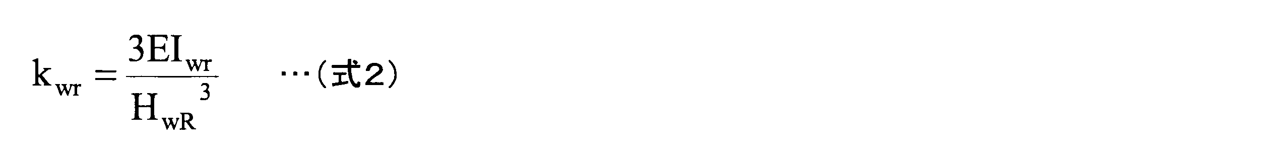
図49に示す素材設計モデル80の1番目の加工領域を加工する場合、仕上げ加工時の軸方向に関する断面2次モーメントIwfは、材料設計モデル70の主板部の長さlと、素材設計モデル80の荒加工後の主板素材部の板厚twrとを用いて、下記の式3のように求められる。

図49に示す素材設計モデル80の1番目の加工領域を加工する場合、仕上げ加工時の静剛性の概算値kwfは、素材のヤング率Eと、ステップS111で算出したHwRと、ステップS105で設定したhwrと、式1で求められる断面2次モーメントIwrと、式3で求められる断面2次モーメントIwfと、を用いて、下記の式4のように求められる。
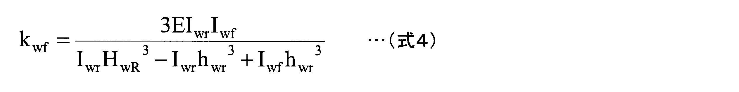
図50に示す素材設計モデル80の1番目の加工領域を加工する場合、荒加工時及び仕上げ加工時の主板素材部の軸方向に関する断面2次モーメントIfwは、材料設計モデル70の主板部の長さlと、素材設計モデル80の主板素材部の板厚Twとを用いて、下記の式5のように求められる。
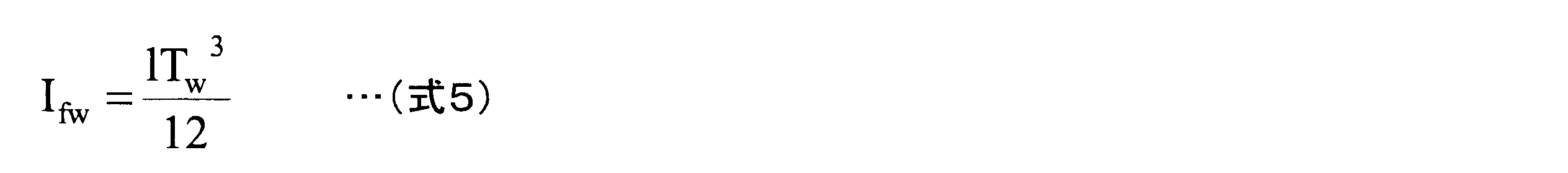
図50に示す素材設計モデル80の1番目の加工領域を加工する場合、荒加工時のフランジ素材部の軸方向に関する断面2次モーメントIfrは、材料設計モデル70の主板部の長さlと、素材設計モデル80のフランジ素材部の板厚Tfとを用いて、下記の式6のように求められる。
図50に示す素材設計モデル80の1番目の加工領域を加工する場合、荒加工時の静剛性の概算値kfrは、素材のヤング率Eと、ステップS111で算出したHwRと、ステップS111で算出したHfRと、式5で求められる断面2次モーメントIfwと、式6で求められる断面2次モーメントIfrとを用いて、下記の式7のように求められる。

図50に示す素材設計モデル80の1番目の加工領域を加工する場合、仕上げ加工時のフランジ素材部の軸方向に関する断面2次モーメントIffは、材料設計モデル70の主板部の長さlと、素材設計モデル80の荒加工後のフランジ素材部の板厚tfrとを用いて、下記の式8のように求められる。

図50に示す素材設計モデル80の1番目の加工領域を加工する場合、仕上げ加工時の静剛性の概算値kffは、素材のヤング率Eと、ステップS111で算出したHwRと、ステップS111で算出したHfRと、ステップS105で設定したhfrと、式5で求められる断面2次モーメントIfwと、式6で求められる断面2次モーメントIfrと、式8で求められる断面2次モーメントIffと、を用いて、下記の式9のように求められる。

以上のように、ステップS112の処理で、制御部12cは、図49に示す素材設計モデル80の1番目の加工領域を加工する場合の荒加工時の静剛性の概算値kwr及び仕上げ加工時の静剛性の概算値kwfと、図50に示す素材設計モデル80の1番目の加工領域を加工する場合の荒加工時の静剛性の概算値kfr及び仕上げ加工時の静剛性の概算値kffとを、算出することができる。制御部12cは、これと同様の方法を用いて、ステップS112の処理で、ステップS101で選択したツールパスを作成する領域に含まれる全ての加工領域において、荒加工時の静剛性の概算値及び仕上げ加工時の静剛性の概算値を算出する。
ステップS112の処理の後、制御部12cは、ステップS104で仮設定した工具の主軸回転数S及び1刃あたりの送り量fzと、ステップS105又はステップS108で仮設定した軸方向切込み量Ad及び半径方向切込み量Rdとに基づいて、切削力を算出する(ステップS113)。ステップS113の処理における切削力の算出の方法について、詳細を以下に説明する。
切削力Fcの算出に必要な切削動力Pcは、ステップS105又はステップS108で仮設定した軸方向切込み量Adと、ステップS105又はステップS108で仮設定した半径方向切込み量Rdと、工具の送り量Fと、比切削抵抗Kcとを用いて、下記の式10のように求められる。

ここで、工具の送り量Fは、ステップS104で仮設定した工具の主軸回転数Sと、ステップS104で仮設定した工具の1刃あたりの送り量fzと、工具の刃数Nとを用いて、下記の式11のように表される。

図51は、1刃あたりの送り量fzと比切削抵抗Kcとの関係の一例を示す図である。比切削抵抗Kcは、図51に示すように、1刃あたりの送り量fzに応じて減衰する関係を有する。この比切削抵抗Kcと1刃あたりの送り量fzとの関係は、工具と素材又は材料との組み合わせによって決まるものである。また、この比切削抵抗Kcと1刃あたりの送り量fzとの関係は、代表的な関係を用いることができる。本実施形態では、制御部12cは、工具と素材又は材料との組み合わせによって決まる関係のデータを有している場合、その関係を用いて、1刃あたりの送り量fzに基づいて比切削抵抗Kcを算出することができる。また、制御部12cは、工具と素材又は材料との組み合わせによって決まる関係のデータを有していない場合、代表的な関係のうち最も工具と素材又は材料との組み合わせに適切な関係を用いて、1刃あたりの送り量fzに基づいて比切削抵抗Kcを算出することができる。
切削力Fcは、式10で表される切削動力Pcと、切削速度Vcとを用いて、算出される。切削速度Vcは、工具径、すなわち工具の直径Daと、工具の主軸回転数Sとを用いて、下記の式12のように表される。

切削力Fcは、式10で表される切削動力Pcと、式12で表される切削速度Vcとを用いて、下記の式13のように求められる。

以上のように、ステップS113の処理で、制御部12cは、工具の切削力Fcを、算出することができる。
ステップS113の処理の後、制御部12cは、ステップS112で算出した荒加工時及び仕上げ加工時のそれぞれにおける静剛性の概算値と、ステップS113で算出した切削力Fcとに基づいて、倒れ量δを算出する(ステップS114)。具体的には、あらゆる種類の静剛性の概算値をまとめてkと記載すると、制御部12cは、倒れ量δ(単位;μm)を、静剛性の概算値kと、切削力Fcとを用いて、下記の式14を用いて算出する。倒れ量δは、切削力Fcと静剛性の概算値kとの比である。

ステップS114の処理の後、制御部12cは、倒れ量δが閾値内にあるか否かを判断する(ステップS116)。制御部12cは、荒加工時の倒れ量δを判断する場合、荒加工時の倒れ量δが、荒加工時の倒れ量の閾値δr以下であるかどうか判断する。制御部12cは、仕上げ加工時の倒れ量δを判断する場合、仕上げ加工時の倒れ量δが、荒加工時の倒れ量の閾値δrとは異なる仕上げ加工時の倒れ量の閾値δf以下であるかどうか判断する。荒加工時の倒れ量の閾値δrは、仕上げ加工時の倒れ量の閾値δfよりも大きい。制御部12cは、荒加工時の倒れ量の閾値δrと仕上げ加工時の倒れ量の閾値δfとの比は、材質の剛性に応じてあらかじめ定められた材質に基づくパラメータの逆数に設定することが好ましい。例えば、制御部12cは、材質がアルミニウムである場合、荒加工時の倒れ量の閾値δrと仕上げ加工時の倒れ量の閾値δfとの比は、1/5の逆数である5に設定することが好ましい。この場合、加工処理の歩留まりを高くすることができ、かつ、加工処理を素早くすることを可能にする。具体的には、荒加工時の倒れ量の閾値δrと仕上げ加工時の倒れ量の閾値δfとは、それぞれ100μmと20μmとが好適に例示される。なお、制御部12cは、ステップS116の処理において、荒加工時と仕上げ加工時とで別々に判断をする。
制御部12cは、倒れ量δが閾値内にある場合(ステップS116でYes)、処理をステップS121へ進める。一方、制御部12cは、倒れ量δが閾値内にない場合(ステップS116でNo)、仮設定した1刃あたりの送り量fz、軸方向切込み量Ad及び半径方向切込み量Rdを減少させる修正をし(ステップS117)、修正した1刃あたりの送り量fz、軸方向切込み量Ad及び半径方向切込み量Rdに基づいて、ステップS111からステップS116までの処理を施す。制御部12cは、荒加工時と仕上げ加工時の一方の倒れ量δのみが閾値内にあり(ステップS116でYes)、他方の倒れ量δのみが閾値内にない(ステップS116でNo)場合、倒れ量δが閾値内にある方についてのみ処理をステップS121へ進め、倒れ量δが閾値内にない方についてのみステップS117の処理及びステップS111からステップS116までの処理を施す。制御部12cは、倒れ量δが閾値内にあると判断するまで、ステップS117の処理及びステップS111からステップS116までの処理を繰り返し施す。
制御部12cは、倒れ量δが閾値内にある場合(ステップS116でYes)、ステップS112で算出した荒加工時及び仕上げ加工時のそれぞれにおける静剛性の概算値と、ステップS113で算出した切削動力Pcとに基づいて、動力比γを算出する(ステップS121)。具体的には、あらゆる種類の静剛性の概算値をまとめてkと記載すると、制御部12cは、動力比γを、静剛性の概算値kと、切削動力Pcとを用いて、下記の式15を用いて算出する。動力比γは、切削動力Pcと静剛性の概算値kとの比である。
ステップS121の処理の後、制御部12cは、動力比γが閾値内にあるか否かを判断する(ステップS122)。制御部12cは、荒加工時の動力比γを判断する場合、荒加工時の動力比γが、荒加工時の動力比の閾値γr以下であるかどうか判断する。制御部12cは、仕上げ加工時の動力比γを判断する場合、仕上げ加工時の動力比γが、荒加工時の動力比の閾値γrとは異なる仕上げ加工時の動力比の閾値γf以下であるかどうか判断する。荒加工時の動力比の閾値γrは、仕上げ加工時の動力比の閾値γfよりも大きい。制御部12cは、荒加工時の動力比の閾値γrと仕上げ加工時の動力比の閾値γfとの比は、材質の剛性に応じてあらかじめ定められた材質に基づくパラメータの逆数に設定することが好ましい。例えば、制御部12cは、材質がアルミニウムである場合、荒加工時の動力比の閾値γrと仕上げ加工時の動力比の閾値γfとの比は、1/5の逆数である5に設定することが好ましい。この場合、加工処理の歩留まりを高くすることができ、かつ、加工処理を素早くすることを可能にする。具体的には、荒加工時の動力比の閾値γrと仕上げ加工時の動力比の閾値γfとは、それぞれ0.6と0.12とが好適に例示される。なお、制御部12cは、ステップS122の処理において、荒加工時と仕上げ加工時とで別々に判断をする。
制御部12cは、動力比γが閾値内にある場合(ステップS122でYes)、仮設定された条件に基づいて、ステップS101で選択した領域についてツールパスを作成し(ステップS125)、処理をステップS126へ進める。一方、制御部12cは、動力比γが閾値内にない場合(ステップS122でNo)、選定した工具の主軸回転数S及び1刃あたりの送り量fzの組み合わせに付された条件通し番号nに1を加える修正をし(ステップS123)、修正した主軸回転数S及び1刃あたりの送り量fzの組み合わせに基づいて、ステップS111からステップS122までの処理を施す。制御部12cは、荒加工時と仕上げ加工時の一方の動力比γのみが閾値内にあり(ステップS122でYes)、他方の動力比γのみが閾値内にない(ステップS122でNo)場合、動力比γが閾値内にある方についてのみ処理をステップS125へ進め、動力比γが閾値内にない方についてのみステップS123の処理及びステップS111からステップS122までの処理を施す。制御部12cは、動力比γが閾値内にあると判断するまで、ステップS123の処理及びステップS111からステップS122までの処理を繰り返し施す。
図52は、加工条件の算出例の一例を示す図である。制御部12cは、ステップS101で選択した領域についてツールパスを作成する場合、図52に示すように、荒加工時及び仕上げ加工時のそれぞれについて、軸方向切込み量Ad及び半径方向切込み量Rdを決定し、荒加工前の素材における加工領域の板厚及び高さ、荒加工後かつ仕上げ加工前の加工領域の板厚及び高さ、仕上げ加工後の材料における加工領域の板厚及び高さを、それぞれ決定する。
ステップS125の処理の後、制御部12cは、全領域でツールパスを作成したか否かを判断する(ステップS126)。具体的には、制御部12cは、ステップS64で読み込んだ要素のうち、加工条件設定用要素を用いてツールパスを作成する全ての要素について、ツールパスを作成したか否かを判断する。制御部12cは、全領域でツールパスを作成した場合(ステップS126でYes)、ツールパス作成ステップS66の処理を終了させて、処理を図28に示すツールパス接続ステップS67へ進める。一方、制御部12cは、全領域でツールパスを作成していない場合(ステップS126でNo)、処理をステップS101へ進め、ツールパスを作成していない領域を選択し(ステップS101)、新たに選択した領域について、上述のようにステップS102からステップS125までの処理を施し、その後にステップS126の処理を施す。制御部12cは、全領域でツールパスを作成するまで、ステップS101からステップS126までの処理を繰り返す。
図28に戻って、ステップS66の処理の後、制御部12cは、ステップS66で要素ごとに作成したツールパスを繋ぎ合わせて、数値制御プログラム19を作成する(ステップS67)。具体的には、制御部12cは、ステップS78で作成されるツールパス作成用要素に含まれる加工の順序に基づいて、ステップS66で要素ごとに作成したツールパスを繋ぎ合わせて、数値制御プログラム19を作成する。すなわち、制御部12cは、把持部vから遠い要素に対応するツールパスから近い要素に対応するツールパスの順に繋ぎ合わせる。また、制御部12cは、フランジを含む要素に対応するツールパス、交錯部を含む要素に対応するツールパス、主板部を含む要素に対応するツールパスの順に繋ぎ合わせる。また、制御部12cは、軸方向に直交する方向に沿った端面を含む要素に対応するツールパス、軸方向に沿った面を含む要素に対応するツールパスの順に繋ぎ合わせる。なお、制御部13cは、交錯部を含む要素に対応するツールパスと主板部を含む要素に対応するツールパスについては、これらの全体で、把持部vから離れた側から順に、各要素に対応するツールパスの順に繋ぎ合わせても良い。
ステップS67の処理の後、制御部12cは、ステップS67で作成された数値制御プログラム19を機械加工装置13の制御部13cで作動させた場合、素材又は材料と、素材又は材料を把持する把持部材及び素材又は材料を加工する工具とが物理的に干渉するか否かを検証する(ステップS69)。制御部12cは、ステップS69の処理で、物理的に干渉すると判断される場合、物理的に干渉しないように数値制御プログラム19を修正する。制御部12cは、ステップS69の処理で、物理的に干渉しないと判断される場合、数値制御プログラム19を修正せず、物理的に干渉しないことを検証済みの状態とする。制御部12cは、ステップS69の処理の後、数値制御プログラム19に対して、機械加工装置13の制御部13cで作動させることを可能にする処理であるポスト処理を施して、機械加工装置13の制御部13cで作動可能な数値制御プログラム19を取得する。これにより、制御部12cは、一連の数値制御プログラムの生成方法のフローを終了させる。
本実施形態に係る数値制御プログラム生成システム12、数値制御プログラムの生成プログラム16、及びそれらによって処理される数値制御プログラムの生成方法は、制御部12cが、要素作成ステップS62で作成した材料の形状に関する要素を、要素読み込みステップS64を介して加工動作の道筋をコード化したツールパスを作成するツールパス作成ステップS66に用いる。そのため、本実施形態に係る数値制御プログラム生成システム12、数値制御プログラムの生成プログラム16、及びそれらによって処理される数値制御プログラムの生成方法は、加工形状に応じた加工条件を設定することができ、加工形状に応じて、加工動作の道筋をコード化したツールパスを作成することができる。
本実施形態に係る数値制御プログラム生成システム12、数値制御プログラムの生成プログラム16、及びそれらによって処理される数値制御プログラムの生成方法は、制御部12cが、要素作成ステップS62で、材料設計モデル70と類似材料設計モデル74とを対比させ、材料設計モデル70と類似材料設計モデル74との該当する部分同士を互いに対応させることで要素を作成し、要素読み込みステップS64で、要素作成ステップS62で互いに対応させた部分について、類似点と差異点とを読み込み、ツールパス作成ステップS66で、類似点を含む要素に対応するツールパスは、類似材料設計モデル74に基づいて作成されたツールパスを用い、差異点を含む要素に対応するツールパスは、類似材料設計モデル74に基づいて作成されたツールパスに対して差異点に応じて変更したツールパスを作成することができる。そのため、本実施形態に係る数値制御プログラム生成システム12、数値制御プログラムの生成プログラム16、及びそれらによって処理される数値制御プログラムの生成方法は、特に類似の形状が多い材料の加工に関する数値制御プログラム19を精度よく作成することができる。
本実施形態に係る数値制御プログラム生成システム12、数値制御プログラムの生成プログラム16、及びそれらによって処理される数値制御プログラムの生成方法は、制御部12cが、要素作成ステップS62で、材料に用いられる素材、材料設計モデル70の形状の型、大きさ、材料設計モデル70に設けられたフランジの角度、フランジの板厚tfの変化の程度、及びマウスホールMHの有無の少なくともいずれかに基づいて、類似材料設計モデル74を選択することができる。そのため、本実施形態に係る数値制御プログラム生成システム12、数値制御プログラムの生成プログラム16、及びそれらによって処理される数値制御プログラムの生成方法は、類似材料設計モデル74を精度よく選択することができる。
本実施形態に係る数値制御プログラム生成システム12、数値制御プログラムの生成プログラム16、及びそれらによって処理される数値制御プログラムの生成方法は、制御部12cが、要素作成ステップS62で、素材又は材料に含まれる面要素を抽出し、面要素のうち最長の2点間の距離の直線を含む面要素を第1の基準面76に設定し、第1の基準面76に直交する方向に沿う面要素のうち最長の2点間の距離の直線を含む面要素を第2の基準面77に設定し、第1の基準面76と第2の基準面77との交線をX軸とし、第1の基準面76に直交するいずれか1つの直線をZ軸として座標軸78を作成し、作成した座標軸78を基準として、素材又は材料の要素を自動で作成することができる。そのため、本実施形態に係る数値制御プログラム生成システム12、数値制御プログラムの生成プログラム16、及びそれらによって処理される数値制御プログラムの生成方法は、要素を自動的に精度よく作成することができる。
本実施形態に係る数値制御プログラム生成システム12、数値制御プログラムの生成プログラム16、及びそれらによって処理される数値制御プログラムの生成方法は、制御部12cが、要素作成ステップS62で、面要素と、端部要素と、2以上の面要素が交錯する交錯部要素とを設定し、素材又は材料の剛性の影響を受ける一部の面要素と、交錯部要素と、を加工動作の条件を設定するための要素である加工条件設定用要素を用いてツールパスを作成する要素に設定することができる。このため、本実施形態に係る数値制御プログラム生成システム12、数値制御プログラムの生成プログラム16、及びそれらによって処理される数値制御プログラムの生成方法は、加工形状に応じて加工条件の設定が必要な要素にのみ効率よく加工条件を設定することができる。
本実施形態に係る数値制御プログラム生成システム12、数値制御プログラムの生成プログラム16、及びそれらによって処理される数値制御プログラムの生成方法は、制御部12cが、要素読み込みステップS64で、加工条件設定用要素を用いてツールパスを作成する要素に設定されているか否かの情報を読み込み、ツールパス作成ステップS66で、加工条件設定用要素に設定されている要素について、加工条件設定用要素に基づいて加工条件を作成し、加工条件を満たすツールパスを作成することができる。このため、本実施形態に係る数値制御プログラム生成システム12、数値制御プログラムの生成プログラム16、及びそれらによって処理される数値制御プログラムの生成方法は、加工形状に応じて加工条件の設定が必要な要素にのみ効率よく加工条件を設定することができる。
本実施形態に係る数値制御プログラム生成システム12、数値制御プログラムの生成プログラム16、及びそれらによって処理される数値制御プログラムの生成方法は、制御部12cが、ツールパス作成ステップS66で、機械加工に用いられる工具の切削動力Pcと要素の静剛性の概算値kとの比である動力比γ及び工具の切削力Fcと静剛性の概算値kとの比である倒れ量δに基づいて、加工条件を生成することができる。このため、本実施形態に係る数値制御プログラム生成システム12、数値制御プログラムの生成プログラム16、及びそれらによって処理される数値制御プログラムの生成方法は、加工形状に応じて加工条件の設定が必要な要素にのみ、精度よく加工条件を設定することができる。また、本実施形態に係る数値制御プログラム生成システム12、数値制御プログラムの生成プログラム16、及びそれらによって処理される数値制御プログラムの生成方法は、歩留まりの高い加工条件を設定することができ、かつ、素早い加工条件を設定することができる。
本実施形態に係る数値制御プログラム生成システム12、数値制御プログラムの生成プログラム16、及びそれらによって処理される数値制御プログラムの生成方法は、制御部12cが、ツールパス接続ステップS67で、素材又は材料を加工する際に把持する把持部vから遠い要素に対応するツールパスから近い要素に対応するツールパスの順に繋ぎ合わせることができる。そのため、本実施形態に係る数値制御プログラム生成システム12、数値制御プログラムの生成プログラム16、及びそれらによって処理される数値制御プログラムの生成方法は、材料の加工の歩留まりが高い数値制御プログラム19を生成することができる。
本実施形態に係る数値制御プログラム生成システム12、数値制御プログラムの生成プログラム16、及びそれらによって処理される数値制御プログラムの生成方法は、制御部12cが、数値制御プログラム検証ステップS69で、ツールパス接続ステップS67の後に、作成された数値制御プログラム19を作動させた場合、素材又は材料と、素材又は材料を把持する把持部材及び素材又は材料を加工する工具とが物理的に干渉するか否かを検証することができる。そのため、素材又は材料の加工に用いる前に数値制御プログラム19が好ましく用いられるかどうかを検証することができる。
本実施形態に係る要素作成ステップS62で実行される要素作成方法は、全ての平面要素を抽出し、平面要素のうち最長の2点間の距離の直線を含む平面要素を第1の基準面76に設定し、第1の基準面76に直交する方向に沿う平面要素のうち最長の2点間の距離の直線を含む平面要素を第2の基準面77に設定し、第1の基準面76と第2の基準面77との交線をX軸とし、第1の基準面76に直交するいずれか1つの直線をZ軸として座標軸78を作成し、作成した座標軸78を基準として、材料の要素を作成することができる。そのため、本実施形態に係る要素作成ステップS62で実行される要素作成方法は、材料の要素を自動的に精度よく作成することができる。
機械加工装置13及び数値制御プログラム19の作用について、以下に説明する。図53は、加工方法のフローの一例を示すフローチャートである。加工方法は、機械加工装置13において、制御部13cが数値制御プログラム19を読み出して処理することで実行される処理方法である。加工方法について、図53を用いて説明する。加工方法は、図53に示すように、把持ステップS131と、切削加工ステップS132と、を含む。以下においては、把持ステップS131及び切削加工ステップS132を適宜、それぞれ単に、ステップS131及びステップS132と称する。
図54は、把持ステップS131の一例である素材50を把持した状態を示す側面図である。図55は、把持ステップS131の一例である素材52を把持した状態を示す側面図である。図56は、把持ステップS131の一例である素材56を把持した状態を示す側面図である。図57は、把持ステップS131の一例である素材62を把持した状態を示す側面図である。図58は、把持ステップS131の一例である素材66を把持した状態を示す側面図である。素材50、素材52、素材56、素材62及び素材66は、それぞれ、図54、図55、図56、図57及び図58に示すように、把持部vで、機械加工装置13の把持部材13vに、主板部の板厚方向に挟み込むように、把持されている。
制御部13cは、素材形状決定システム11において、制御部11cが素材形状の決定プログラム15を読み出して処理することで実行される素材形状の決定方法により決定された素材を、把持部vで、機械加工装置13の把持部材13vに、主板素材部の板厚方向に挟み込むように、把持させる(ステップS131)。これにより、把持部材13vに把持された素材の主板素材部は、把持部vに対して鉛直方向の上側に沿う方向に向けられる。そして、把持部材13vに把持された把持部vは、素材の固定端となり、把持部材13vに把持されていない素材の主板素材部及びフランジ素材部は、素材の自由端となる。そのため、このように把持された素材は、加工処理を受けても、素材内に残留応力が蓄積しないので、加工して得られる材料に蓄積する残留応力が大幅に低減される。
ステップS131の処理の後、制御部13cは、機械加工装置13に対し、機械加工装置13の把持部材13vに把持させた素材を切削加工させる(ステップS132)。制御部13cは、機械加工装置13に対し、数値制御プログラム19に組み込まれたツールパスの順に、素材を切削加工させる。
切削加工ステップS132について、詳細を以下に説明する。図59は、切削加工ステップS132のフローの詳細の一例を示すフローチャートである。切削加工ステップS132は、図59に示すように、フランジ加工ステップS141と、交錯部加工ステップS142と、主板部加工ステップS143と、を含む。以下においては、フランジ加工ステップS141、交錯部加工ステップS142及び主板部加工ステップS143を適宜、それぞれ単に、ステップS141、ステップS142及びステップS143と称する。
切削加工ステップS132において、まず、制御部13cは、機械加工装置13に対し、素材のフランジ素材部を切削加工させてフランジを形成させる(ステップS141)。制御部13cは、機械加工装置13に対し、フランジ位置が把持部vから離れたフランジに関するフランジ素材部から順に、切削加工させる。また、制御部13cは、機械加工装置13に対し、フランジ素材部の主板素材部から離れた先端部から順に、切削加工させる。
ステップS141の処理の後、制御部13cは、機械加工装置13に対し、素材の交錯素材部を切削加工させて交錯部を形成させる(ステップS142)。制御部13cは、機械加工装置13に対し、フランジ位置が把持部vから離れたフランジが交錯する交錯素材部から順に、切削加工させる。また、制御部13cは、機械加工装置13に対し、交錯素材部の主板素材部から離れた側から順に、切削加工させる。
ステップS142の処理の後、制御部13cは、機械加工装置13に対し、素材の主板素材部を切削加工させて主板部を形成させる(ステップS143)。制御部13cは、機械加工装置13に対し、主板素材部の把持部vから離れた側から順に、切削加工させる。なお、制御部13cは、機械加工装置13に対し、交錯素材部の加工と主板素材部の加工については、これらの全体で、把持部vから離れた側から順に切削加工させても良い。
図60は、切削加工ステップS132のフローの詳細の別の一例を示すフローチャートである。切削加工ステップS132は、図60に示すように、端面切削加工ステップS151と、面切削加工ステップS152と、を含む。以下においては、端面切削加工ステップS151及び面切削加工ステップS152を適宜、それぞれ単に、ステップS151及びステップS152と称する。
切削加工ステップS132において、まず、制御部13cは、機械加工装置13に対し、素材の軸方向の両端の端面を切削加工させる(ステップS151)。制御部13cは、機械加工装置13に対し、フランジ素材部の軸方向の両端の端面と、交錯素材部の軸方向の両端の端面と、主板素材部の軸方向の両端の端面とを、3度に分けて切削加工させてもよいし、1度に切削加工させても良い。
ステップS151の処理の後、制御部13cは、機械加工装置13に対し、素材の軸方向に沿った面要素等を切削加工させる(ステップS152)。制御部13cは、機械加工装置13に対し、フランジ素材部の軸方向に沿った両側の面要素と、交錯素材部の軸方向に沿った両側の複雑な曲面要素と、主板素材部の軸方向に沿った両端の面要素とを、上記のステップS141、ステップS142及びステップS143の順序に従って切削加工させることができる。
切削加工ステップS132の処理の後、制御部13cは、素材の切断部を、切り離しやすいように、カットアウトの形状に応じた複数のタブ形状に加工してから、材料と把持部vとの間を切断加工する。このようにして、機械加工装置13において、制御部13cが数値制御プログラム19を読み出して処理することで実行される処理方法である加工方法により、素材から材料が加工される。
本実施形態に係る機械加工装置13、数値制御プログラム19、及びそれらによって処理される加工方法は、本実施形態に係る素材形状決定システム11、素材形状の決定プログラム15、及びそれらによって処理される素材形状の決定方法により決定された素材を加工処理して、材料を得る加工である。また、本実施形態に係る機械加工装置13、数値制御プログラム19、及びそれらによって処理される加工方法は、数値制御プログラム19が、本実施形態に係る数値制御プログラム生成システム12、数値制御プログラムの生成プログラム16、及びそれらによって処理される数値制御プログラムの生成方法で生成されたものである。そのため、本実施形態に係る機械加工装置13、数値制御プログラム19、及びそれらによって処理される加工方法は、加工形状に応じて、可能な限り小さい素材形状から、素材又は材料の内部に蓄積される残留応力を低減した加工をすることができるので、効率よく、精度よく、素早く、かつ歩留まりの高い加工をすることができる。
本実施形態に係る機械加工装置13、数値制御プログラム19、及びそれらによって処理される加工方法は、フランジ加工ステップS141、交錯部加工ステップS142、主板部加工ステップS143の順で行われるため、把持部vから遠い側から近い側に順に加工されるので、加工領域よりも把持部vに近い側の静剛性の概算値が加工中に減少することがないため、より歩留まりが高い加工をすることができる。
本実施形態に係る機械加工装置13、数値制御プログラム19、及びそれらによって処理される加工方法は、端面切削加工ステップS151、面切削加工ステップS152の順で行われるため、より効率よく、かつ、より素早い加工をすることができる。
本実施形態に係る機械加工装置13、数値制御プログラム19、及びそれらによって処理される加工方法は、数値制御プログラム19に組み込まれているように、フランジ加工ステップS141及び交錯部加工ステップS142では、いずれも、加工中において、フランジ素材部又は主板素材部の高さとフランジ素材部又は主板素材部の板厚との比が、材質の剛性に応じてあらかじめ定められた材質に基づくパラメータの逆数以下、例えば、材質がアルミニウムである場合にはパラメータ1/5の逆数である5以下にするように加工処理が行われる。そのため、本実施形態に係る機械加工装置13、数値制御プログラム19、及びそれらによって処理される加工方法は、より素早く、かつ、歩留まりの高い加工をすることができる。
本実施形態に係る機械加工装置13、数値制御プログラム19、及びそれらによって処理される加工方法は、数値制御プログラム19に組み込まれているように、フランジ加工ステップS141、交錯部加工ステップS142、主板部加工ステップS143のいずれにおいても、素材を材料の形状に近づけるための切削加工である荒加工が行われ、荒加工の後に、素材を材料の形状に仕上げるための切削加工である仕上げ加工が行われる。そのため、本実施形態に係る機械加工装置13、数値制御プログラム19、及びそれらによって処理される加工方法は、より効率よく、より素早く、かつ、より精度の高い加工をすることができる。
本実施形態に係る機械加工装置13、数値制御プログラム19、及びそれらによって処理される加工方法は、数値制御プログラム19に組み込まれているように、荒加工の加工代と、仕上げ加工の加工代との比が、材質の剛性に応じてあらかじめ定められた材質に基づくパラメータの逆数以下、例えば、材質がアルミニウムである場合にはパラメータ1/5の逆数である5以下にするように加工処理が行われる。そのため、本実施形態に係る機械加工装置13、数値制御プログラム19、及びそれらによって処理される加工方法は、より効率よく、より素早く、かつ、より精度の高い加工をすることができる。
図44に示されたフランジ穴あけ加工要素EL3及び主板部穴あけ加工要素EL6に例示される穴あけ加工要素を含む場合の加工方法について、以下に説明する。図61は、穴あけステップS163を含む加工方法のフローの詳細の一例を示すフローチャートである。穴あけ加工要素を含む場合の加工方法は、図61に示すように、穴あけ前仕上げ加工ステップS161と、穴あけ領域荒加工ステップS162と、穴あけステップS163と、穴あけ領域仕上げ加工ステップS164と、を含む。以下においては、穴あけ前仕上げ加工ステップS161、穴あけ領域荒加工ステップS162、穴あけステップS163及び穴あけ領域仕上げ加工ステップS164を適宜、それぞれ単に、ステップS161、ステップS162、ステップS163及びステップS164と称する。
図62は、穴あけ加工部位92を含む主板素材部91の加工の順の一例を示す図である。図63は、穴あけ加工部位95を含むフランジ素材部94の加工の順の一例を示す図である。図62及び図63において、図では省略されているが、紙面の下側が把持部vとなっている。制御部13cは、機械加工装置13に対し、図62に示す数字の順に、すなわち、把持部vから遠い側から近い側に向かう順に、紙面の上側から下側に向かう順に、主板素材部91を切削加工させる。制御部13cは、機械加工装置13に対し、図63に示す数字の順に、すなわち、主板部から遠い側から近い側に向かう順に、フランジ素材部94を切削加工させる。
図44に示された主板部穴あけ加工要素EL6に例示される穴あけ加工要素を含む場合の加工方法において、制御部13cは、穴あけ加工部位92よりも把持部vから遠い領域、すなわち図62に示された主板素材部91よりも図62の紙面の上側に加工領域がある場合、機械加工装置13に対し、この加工領域を仕上げ加工させる(ステップS161)。制御部13cは、穴あけ加工部位92よりも把持部vから遠い領域、すなわち図62に図示された主板素材部91よりも図62の紙面の上側に加工領域がない場合、ステップS161の処理を省略しても良い。
ステップS161の処理の後、制御部13cは、機械加工装置13に対し、穴あけ加工部位92を含む領域、すなわち図62に示された1番と2番の領域を荒加工させる(ステップS162)。ステップS162の処理の後、制御部13cは、穴あけ加工部位92よりも把持部vから遠い領域、すなわち図62に示された3番と4番の領域がある場合、機械加工装置13に対し、この3番と4番の領域を仕上げ加工させる。その後、制御部13cは、機械加工装置13に対し、穴あけ加工部位92、すなわち図62に示された5番の領域を、穴あけ加工させる(ステップS163)。ステップS163の処理の後、制御部13cは、機械加工装置13に対し、穴あけ加工領域を含む領域、すなわち図62に示された6番と7番の領域を、仕上げ加工させる(ステップS164)。ステップS164の処理の後、上述の加工処理と同様に、制御部13cは、機械加工装置13に対し、図62に示された8番から13番までの加工処理をさせる。
図44に示されたフランジ穴あけ加工要素EL3に例示される穴あけ加工要素を含む場合の加工方法において、制御部13cは、穴あけ加工部位95よりも主板部及び把持部vから遠い領域、すなわち図63に示されたフランジ素材部94よりも図63の紙面の右側に加工領域がある場合、機械加工装置13に対し、この加工領域を仕上げ加工させる(ステップS161)。制御部13cは、穴あけ加工部位95よりも主板部及び把持部vから遠い領域、すなわち図63に図示されたフランジ素材部94よりも図63の紙面の右側に加工領域がない場合、ステップS161の処理を省略しても良い。
ステップS161の処理の後、制御部13cは、機械加工装置13に対し、穴あけ加工部位95を含む領域、すなわち図63に示された1番と2番の領域を荒加工させる(ステップS162)。ステップS162の処理の後、制御部13cは、穴あけ加工部位95よりも主板部及び把持部vから遠い領域、すなわち図63に示された3番と4番の領域がある場合、機械加工装置13に対し、この3番と4番の領域を仕上げ加工させる。その後、制御部13cは、機械加工装置13に対し、穴あけ加工部位95、すなわち図63に示された5番の領域を、穴あけ加工させる(ステップS163)。ステップS163の処理の後、制御部13cは、機械加工装置13に対し、穴あけ加工領域を含む領域、すなわち図63に示された6番と7番の領域を、仕上げ加工させる(ステップS164)。ステップS164の処理の後、上述の加工処理と同様に、制御部13cは、機械加工装置13に対し、図63に示された8番から13番までの加工処理をさせる。
穴あけ加工要素を含む場合の加工方法では、穴をあける領域の荒加工である穴あけ領域荒加工ステップS162が行われた後で、穴をあける領域の仕上げ加工である穴あけ領域仕上げ加工ステップS164が行われる前に、穴あけステップS163が行われる。そのため、穴あけステップS163で、荒加工領域まで穴あけ加工する必要がなく、かつ、穴あけステップS163で荒れる可能性がある表面を穴あけ領域仕上げ加工ステップS164で所望の形状に仕上げることができる。よって、この穴あけ加工要素を含む場合の加工方法は、素早くかつ精度よく穴あけ加工をすることができる。
穴あけ加工要素を含む場合の加工方法では、穴をあける領域よりも把持部から遠い領域の仕上げ加工である穴あけ前仕上げ加工ステップS161が行われた後で、穴をあける領域の仕上げ加工である穴あけ領域仕上げ加工ステップS164が行われる前に、穴あけステップS163が行われる。そのため、穴あけステップS163で、穴あけ前仕上げ加工ステップS161の際の静剛性が低減することを防止することができる。よって、この穴あけ加工要素を含む場合の加工方法は、穴をあける領域よりも把持部から遠い領域の加工についても、素早くかつ精度よく加工をすることができる。
窪み部形成加工要素を含む場合の加工方法について、以下に説明する。図64は、窪み部形成ステップS174を含む加工方法のフローの詳細の一例を示すフローチャートである。窪み部形成加工要素を含む場合の加工方法は、図64に示すように、窪み部形成前仕上げ加工ステップS171と、窪み部形成領域荒加工ステップS172と、窪み部形成領域仕上げ加工ステップS173と、窪み部形成ステップS174と、を含む。以下においては、窪み部形成前仕上げ加工ステップS171、窪み部形成領域荒加工ステップS172、窪み部形成領域仕上げ加工ステップS173及び窪み部形成ステップS174を適宜、それぞれ単に、ステップS171、ステップS172、ステップS173及びステップS174と称する。
図65は、窪み部形成部位98を含む主板素材部97の加工の順の一例を示す図である。図65において、紙面の下側が把持部vとなっている。制御部13cは、機械加工装置13に対し、図65に示す数字の順に、すなわち、把持部vから遠い側から近い側に向かう順に、紙面の上側から下側に向かう順に、主板素材部97を切削加工させる。
窪み部形成加工要素を含む場合の加工方法において、制御部13cは、窪み部形成部位98よりも把持部vから遠い領域、すなわち図65に示された主板素材部97よりも図65の紙面の上側に加工領域がある場合、機械加工装置13に対し、この加工領域を仕上げ加工させる(ステップS171)。制御部13cは、窪み部形成部位98よりも把持部vから遠い領域、すなわち図65に図示された主板素材部97よりも図65の紙面の上側に加工領域がない場合、ステップS171の処理を省略しても良い。
ステップS171の処理の後、制御部13cは、機械加工装置13に対し、窪み部形成部位98を含む領域の一部、すなわち図65に示された1番と2番の領域を荒加工させる(ステップS172)。ステップS172の処理の後、制御部13cは、窪み部形成部位98よりも把持部vから遠い領域がある場合、機械加工装置13に対し、この領域を仕上げ加工させる。その後、制御部13cは、機械加工装置13に対し、窪み部形成部位98を含む領域の一部、すなわち図65に示された3番、4番、5番及び6番の領域を、仕上げ加工させる(ステップS173)。ステップS173の処理の後、制御部13cは、機械加工装置13に対し、窪み部形成部位98の一部、すなわち図65に示された7番の領域を、窪み部形成加工させる(ステップS174)。なお、制御部13cは、機械加工装置13に対し、窪み部形成部位98の一部、すなわち図65に示された7番の領域を、1段階で窪み部形成加工させる必要はなく、複数の段階に分離して窪み部形成加工させてもよい。
また、ステップS171からステップS174までの一連の処理で、図65に示す7番の領域を窪み部形成加工した後、制御部13cは、再びステップS172に戻って、機械加工装置13に対し、窪み部形成部位98を含む領域の一部、すなわち図65に示された8番と9番の領域を荒加工させる(ステップS172)。このステップS172の処理の後、制御部13cは、窪み部形成部位98よりも把持部vから遠い領域がある場合、機械加工装置13に対し、この領域を仕上げ加工させる。その後、制御部13cは、機械加工装置13に対し、窪み部形成部位98を含む領域の一部、すなわち図65に示された10番、11番、12番及び13番の領域を、仕上げ加工させる(ステップS173)。このステップS173の処理の後、制御部13cは、機械加工装置13に対し、窪み部形成部位98の一部、すなわち図65に示された12番及び15番の領域を、順次、窪み部形成加工させる(ステップS174)。なお、制御部13cは、機械加工装置13に対し、窪み部形成部位98の一部、すなわち図65に示された12番及び15番の領域を、2段階で窪み部形成加工させる必要はなく、3段階以上に分離して窪み部形成加工させてもよい。
窪み部形成加工要素を含む場合の加工方法では、窪み部形成部位98を含む領域の仕上げ加工の加工ピッチ、すなわち図65に示す3番から6番及び10番から14番の加工ピッチに合わせて、窪み部形成領域仕上げ加工ステップS173の後に逐次、窪み部形成ステップS174が行われる。そのため、窪み部形成ステップS174で、窪み部形成前仕上げ加工ステップS171、窪み部形成領域荒加工ステップS172及び窪み部形成領域仕上げ加工ステップS173の際の静剛性が低減することを防止することができる。よって、窪み部形成加工要素を含む場合の加工方法は、窪み部を形成する領域よりも把持部から遠い領域の加工についても、素早くかつ精度よく加工をすることができる。
10 材料加工システム
11 素材形状決定システム
11c,12c,13c 制御部
12 数値制御プログラム生成システム
13 機械加工装置
15 素材形状の決定プログラム
16 数値制御プログラムの生成プログラム
17 コンピュータ支援設計プログラム
18 コンピュータ支援製造プログラム
19 数値制御プログラム
20,22,24,26,28,32,34,36,38 材料
20w,22w,24w,26w,28w,32w,34w,36w,38w 主板部
22f,24f,26f1,26f2,28f1,28f2,32f,34f,36f1,36f2,38f1,38f2 フランジ
22m,24m,26m,28m,32m,34m,36m,38m 交錯部
41 曲面部
42 テーパ部
43,44 段差部
50,52,54,56,58,62,64,66,68 素材
50W,52W,54W,56W,58W,62W,64W,66W,68W 主板素材部
52F,54F,56F1,56F2,58F1,58F2,62F,64F,66F1,66F2,68F1,68F2 フランジ素材部
52M,54M,56M,58M,62M,64M,66M,68M 交錯素材部
70 材料設計モデル
72 識別条件
74 類似材料設計モデル
76 第1の基準面
77 第2の基準面
78 座標軸
79 モデル要素名
80 素材設計モデル
82 要素分割方法
83 荒加工工具条件
84 仕上げ加工工具条件
91,97 主板素材部
92,95 穴あけ加工部位
94 フランジ素材部
98 窪み部形成部位
Claims (12)
- 材料の加工の際に行われる機械加工の加工動作を制御するための数値制御プログラムの生成方法であって、
コンピュータ支援設計プログラムで実行して、前記材料の設計モデルである材料設計モデルに基づいて前記材料の形状に関する要素を作成する要素作成ステップと、
前記コンピュータ支援設計プログラムで作成した前記要素をコンピュータ支援製造プログラムで読み込む要素読み込みステップと、
前記コンピュータ支援製造プログラムを実行して、読み込んだ前記要素ごとに前記加工動作の道筋をコード化したツールパスを作成するツールパス作成ステップと、
前記コンピュータ支援製造プログラムを実行して、作成した前記ツールパスを繋ぎ合わせて数値制御プログラムを作成するツールパス接続ステップと、
を含むことを特徴とする数値制御プログラムの生成方法。 - 前記要素作成ステップでは、予め準備された既存の材料の設計モデルのうち、前記材料設計モデルに最も形状が近い類似材料設計モデルを、前記材料設計モデルと対比させ、前記材料設計モデルと前記類似材料設計モデルとの該当する部分同士を互いに対応させることで、前記要素を作成し、
前記要素読み込みステップでは、前記要素作成ステップで互いに対応させた部分について、類似点と差異点とを読み込み、
前記ツールパス作成ステップでは、前記類似点を含む前記要素に対応するツールパスは、前記類似材料設計モデルに基づいて作成されたツールパスを用い、前記差異点を含む前記要素に対応するツールパスは、前記類似材料設計モデルに基づいて作成されたツールパスに対して前記差異点に応じて変更したツールパスを作成する、
ことを特徴とする請求項1に記載の数値制御プログラムの生成方法。 - 前記要素作成ステップでは、前記材料に用いられる素材、前記材料設計モデルの形状の型、大きさ、前記材料設計モデルに設けられたフランジの角度、前記フランジの板厚の変化の程度、及びマウスホールの有無の少なくともいずれかに基づいて、前記類似材料設計モデルを選択することを特徴とする請求項2に記載の数値制御プログラムの生成方法。
- 前記要素作成ステップでは、
前記材料に含まれる面要素を抽出し、
前記面要素のうち最長の2点間の距離の直線を含む前記面要素を第1の基準面に設定し、
前記第1の基準面に直交する方向に沿う前記面要素のうち最長の2点間の距離の直線を含む前記面要素を第2の基準面に設定し、
前記第1の基準面と前記第2の基準面との交線をX軸とし、前記第1の基準面に直交するいずれか1つの直線をZ軸として座標軸を作成し、
作成した前記座標軸を基準として、前記材料の要素を作成することを特徴とする請求項1から請求項3のいずれか1項に記載の数値制御プログラムの生成方法。 - 前記要素作成ステップでは、面要素と、端部要素と、2以上の面要素が交錯する交錯部要素とを設定し、前記材料の剛性の影響を受ける一部の前記面要素と、前記交錯部要素と、を前記加工動作の条件を設定するための要素である加工条件設定用要素を用いて前記ツールパスを作成する前記要素に設定することを特徴とする請求項1から請求項4のいずれか1項に記載の数値制御プログラムの生成方法。
- 前記要素読み込みステップでは、前記加工条件設定用要素に設定されているか否かの情報を読み込み、
前記ツールパス作成ステップでは、前記加工条件設定用要素を用いて前記ツールパスを作成する要素に設定されている要素について、加工条件設定用要素に基づいて加工条件を作成し、前記加工条件を満たすツールパスを作成することを特徴とする請求項5に記載の数値制御プログラムの生成方法。 - 前記ツールパス作成ステップでは、前記機械加工に用いられる工具の切削動力と前記要素の静剛性の概算値との比である動力比及び前記工具の切削力と前記静剛性の概算値との比である倒れ量に基づいて、前記加工条件が生成されることを特徴とする請求項6に記載の数値制御プログラムの生成方法。
- 前記ツールパス接続ステップでは、前記材料を加工する際に把持する把持部から遠い前記要素に対応する前記ツールパスから近い前記要素に対応する前記ツールパスの順に繋ぎ合わせることを特徴とする請求項1から請求項7のいずれか1項に記載の数値制御プログラムの生成方法。
- 数値制御プログラム検証ステップと、をさらに有し、
数値制御プログラム検証ステップでは、前記ツールパス接続ステップの後に、作成された数値制御プログラムを作動させた場合、前記材料と、前記材料を把持する把持部材及び前記材料を加工する工具とが物理的に干渉するか否かを検証することを特徴とする請求項1から請求項8のいずれか1項に記載の数値制御プログラムの生成方法。 - 材料の設計モデルの要素を作成する要素作成方法であって、
全ての平面要素を抽出し、
前記平面要素のうち最長の2点間の距離の直線を含む前記平面要素を第1の基準面に設定し、
前記第1の基準面に直交する方向に沿う前記平面要素のうち最長の2点間の距離の直線を含む前記平面要素を第2の基準面に設定し、
前記第1の基準面と前記第2の基準面との交線をX軸とし、前記第1の基準面に直交するいずれか1つの直線をZ軸として座標軸を作成し、
作成した前記座標軸を基準として、前記材料の要素を作成することを特徴とする要素作成方法。 - 材料の加工の際に行われる機械加工の加工動作を制御するための数値制御プログラムの生成システムであって、
制御部を含み、
前記制御部は、
コンピュータ支援設計プログラムで実行して、前記材料の設計モデルに基づいて前記材料の形状に関する要素を作成する要素作成ステップと、
前記コンピュータ支援設計プログラムで作成した前記要素をコンピュータ支援製造プログラムで読み込む要素読み込みステップと、
前記コンピュータ支援製造プログラムを実行して、読み込んだ前記要素ごとに前記加工動作の道筋をコード化したツールパスを作成するツールパス作成ステップと、
前記コンピュータ支援製造プログラムを実行して、作成した前記ツールパスを繋ぎ合わせて数値制御プログラムを作成するツールパス接続ステップと、
を含む各ステップを実行することを特徴とする数値制御プログラムの生成システム。 - 材料の加工の際に行われる機械加工の加工動作を制御するための数値制御プログラムをコンピュータに生成させる数値制御プログラムの生成プログラムであって、
前記コンピュータに、
コンピュータ支援設計プログラムで実行して、前記材料の設計モデルに基づいて前記材料の形状に関する要素を作成する要素作成ステップと、
前記コンピュータ支援設計プログラムで作成した前記要素をコンピュータ支援製造プログラムで読み込む要素読み込みステップと、
前記コンピュータ支援製造プログラムを実行して、読み込んだ前記要素ごとに前記加工動作の道筋をコード化したツールパスを作成するツールパス作成ステップと、
前記コンピュータ支援製造プログラムを実行して、作成した前記ツールパスを繋ぎ合わせて数値制御プログラムを作成するツールパス接続ステップと、
を実行させることを特徴とする数値制御プログラムの生成プログラム。
Priority Applications (2)
| Application Number | Priority Date | Filing Date | Title |
|---|---|---|---|
| EP17843220.9A EP3477408A4 (en) | 2016-08-23 | 2017-07-06 | METHOD FOR PRODUCING A NUMERICALLY CONTROLLED PROGRAM, ELEMENTS PRODUCTION METHOD, GENERATION SYSTEM AND PRODUCTION PROGRAM |
| US16/318,871 US10824133B2 (en) | 2016-08-23 | 2017-07-06 | Method for generating numerical control program, element creation method, generation system, and generation program |
Applications Claiming Priority (2)
| Application Number | Priority Date | Filing Date | Title |
|---|---|---|---|
| JP2016162997A JP6719331B2 (ja) | 2016-08-23 | 2016-08-23 | 数値制御プログラムの生成方法、要素作成方法、生成システム及び生成プログラム |
| JP2016-162997 | 2016-08-23 |
Publications (1)
| Publication Number | Publication Date |
|---|---|
| WO2018037732A1 true WO2018037732A1 (ja) | 2018-03-01 |
Family
ID=61245864
Family Applications (1)
| Application Number | Title | Priority Date | Filing Date |
|---|---|---|---|
| PCT/JP2017/024850 Ceased WO2018037732A1 (ja) | 2016-08-23 | 2017-07-06 | 数値制御プログラムの生成方法、要素作成方法、生成システム及び生成プログラム |
Country Status (4)
| Country | Link |
|---|---|
| US (1) | US10824133B2 (ja) |
| EP (1) | EP3477408A4 (ja) |
| JP (1) | JP6719331B2 (ja) |
| WO (1) | WO2018037732A1 (ja) |
Families Citing this family (8)
| Publication number | Priority date | Publication date | Assignee | Title |
|---|---|---|---|---|
| JP6691851B2 (ja) * | 2016-08-23 | 2020-05-13 | 三菱重工業株式会社 | 素材形状の決定方法、加工方法、素材形状の決定システム及び素材形状の決定プログラム |
| JP7106321B2 (ja) | 2018-03-29 | 2022-07-26 | 三菱重工業株式会社 | 工具選定装置、方法、及びプログラム、並びにncプログラム作成システム |
| CN110262400B (zh) * | 2019-05-20 | 2020-11-13 | 河源龙记金属制品有限公司 | 一种模板加工程式生成方法和模板的加工方法 |
| WO2022024975A1 (ja) * | 2020-07-30 | 2022-02-03 | ファナック株式会社 | 数値制御装置、及び制御方法 |
| WO2022163839A1 (ja) * | 2021-02-01 | 2022-08-04 | ファナック株式会社 | 工作機械の段取り機能を備えた数値制御装置及び記憶媒体 |
| KR102840541B1 (ko) * | 2024-10-28 | 2025-08-04 | 주식회사 볼트앤너트 | 3차원 오브젝트의 가공 영역 최적화 툴패스를 생성하는 서버 및 그 동작 방법 |
| KR102840528B1 (ko) * | 2024-10-28 | 2025-08-04 | 주식회사 볼트앤너트 | 3차원 오브젝트를 가공하기 위한 최적의 툴패스를 생성하는 장치 및 그 동작 방법 |
| CN121165620B (zh) * | 2025-11-21 | 2026-03-20 | 中国机械总院集团青岛分院有限公司 | 一种数控机床加工程序自动生成方法及系统 |
Citations (8)
| Publication number | Priority date | Publication date | Assignee | Title |
|---|---|---|---|---|
| JPH05108132A (ja) * | 1991-10-21 | 1993-04-30 | Omron Corp | 加工パターン決定装置 |
| JPH08115117A (ja) * | 1994-10-18 | 1996-05-07 | Imao Corp:Kk | 加工シミュレーションによる干渉チェック方法 |
| JPH09325804A (ja) * | 1996-06-06 | 1997-12-16 | Toshiba Mach Co Ltd | ロール加工用ncプログラム自動生成装置 |
| JP2001084018A (ja) * | 1999-07-15 | 2001-03-30 | Toshiba Corp | 3次元cad/camシステム及びモデルデータを記録した記憶媒体 |
| JP2002297211A (ja) * | 2001-03-30 | 2002-10-11 | Toyoda Mach Works Ltd | Ncプログラムの集約方法。 |
| JP2006004128A (ja) * | 2004-06-17 | 2006-01-05 | Mori Seiki Co Ltd | 干渉確認装置 |
| JP2008140358A (ja) | 2006-11-10 | 2008-06-19 | Olympus Corp | 情報処理システム、ncプログラム作成方法、加工形状認識プログラム |
| JP2014194657A (ja) * | 2013-03-28 | 2014-10-09 | Kobe Steel Ltd | 溶接線情報設定装置、プログラム、自動教示システム、および溶接線情報設定方法 |
Family Cites Families (8)
| Publication number | Priority date | Publication date | Assignee | Title |
|---|---|---|---|---|
| JP3702496B2 (ja) * | 1995-07-10 | 2005-10-05 | 三菱電機株式会社 | 数値制御装置を用いた加工方法 |
| US6804568B1 (en) | 1999-07-15 | 2004-10-12 | Kabushiki Kaisha Toshiba | 3-D CAD/CAM data transfer method, 3-D CAD apparatus, 3-D CAM apparatus, 3-D CAD/CAM apparatus, NC process apparatus, and storage medium |
| JP2003058215A (ja) * | 2001-08-09 | 2003-02-28 | Mori Seiki Co Ltd | 類似加工データ検索装置及び自動プログラミング装置 |
| US7894930B2 (en) * | 2008-02-07 | 2011-02-22 | Dp Technology, Corp. | Method and device for composite machining based on tool-path pattern types with tool axis orientation rules |
| KR20100068535A (ko) * | 2008-12-15 | 2010-06-24 | 두산인프라코어 주식회사 | 가공피쳐에 기반한 경험기반 nc 프로그래밍 및 공작물 가공 방법 |
| JP5035490B2 (ja) | 2010-05-20 | 2012-09-26 | 三菱電機株式会社 | 数値制御プログラム生成方法およびその装置並びにその方法をコンピュータに実行させるプログラム |
| JP5436731B1 (ja) | 2013-05-15 | 2014-03-05 | 三菱電機株式会社 | 数値制御加工プログラム作成装置 |
| WO2015138529A1 (en) * | 2014-03-11 | 2015-09-17 | Ametek Precitech, Inc. | Edge treatment process |
-
2016
- 2016-08-23 JP JP2016162997A patent/JP6719331B2/ja active Active
-
2017
- 2017-07-06 EP EP17843220.9A patent/EP3477408A4/en not_active Withdrawn
- 2017-07-06 WO PCT/JP2017/024850 patent/WO2018037732A1/ja not_active Ceased
- 2017-07-06 US US16/318,871 patent/US10824133B2/en active Active
Patent Citations (8)
| Publication number | Priority date | Publication date | Assignee | Title |
|---|---|---|---|---|
| JPH05108132A (ja) * | 1991-10-21 | 1993-04-30 | Omron Corp | 加工パターン決定装置 |
| JPH08115117A (ja) * | 1994-10-18 | 1996-05-07 | Imao Corp:Kk | 加工シミュレーションによる干渉チェック方法 |
| JPH09325804A (ja) * | 1996-06-06 | 1997-12-16 | Toshiba Mach Co Ltd | ロール加工用ncプログラム自動生成装置 |
| JP2001084018A (ja) * | 1999-07-15 | 2001-03-30 | Toshiba Corp | 3次元cad/camシステム及びモデルデータを記録した記憶媒体 |
| JP2002297211A (ja) * | 2001-03-30 | 2002-10-11 | Toyoda Mach Works Ltd | Ncプログラムの集約方法。 |
| JP2006004128A (ja) * | 2004-06-17 | 2006-01-05 | Mori Seiki Co Ltd | 干渉確認装置 |
| JP2008140358A (ja) | 2006-11-10 | 2008-06-19 | Olympus Corp | 情報処理システム、ncプログラム作成方法、加工形状認識プログラム |
| JP2014194657A (ja) * | 2013-03-28 | 2014-10-09 | Kobe Steel Ltd | 溶接線情報設定装置、プログラム、自動教示システム、および溶接線情報設定方法 |
Non-Patent Citations (1)
| Title |
|---|
| See also references of EP3477408A4 * |
Also Published As
| Publication number | Publication date |
|---|---|
| JP2018032157A (ja) | 2018-03-01 |
| US10824133B2 (en) | 2020-11-03 |
| EP3477408A4 (en) | 2019-07-31 |
| EP3477408A1 (en) | 2019-05-01 |
| JP6719331B2 (ja) | 2020-07-08 |
| US20190235474A1 (en) | 2019-08-01 |
Similar Documents
| Publication | Publication Date | Title |
|---|---|---|
| WO2018037732A1 (ja) | 数値制御プログラムの生成方法、要素作成方法、生成システム及び生成プログラム | |
| US10488847B2 (en) | Profit milling | |
| US8005567B2 (en) | Method and control system for generating machine tool control data | |
| US20160246897A1 (en) | Systems and methods for bevel feature recognition and bevel profile generation | |
| CN100595705C (zh) | 孔加工用nc程序生成装置 | |
| CN114065432B (zh) | 一种基于工艺流程的制造成本估算方法 | |
| US20080109097A1 (en) | Machining step generating apparatus | |
| JP6691851B2 (ja) | 素材形状の決定方法、加工方法、素材形状の決定システム及び素材形状の決定プログラム | |
| US6850814B2 (en) | Machining program preparation apparatus | |
| Lim et al. | Exact tool sizing for feature accessibility | |
| CN102906653B (zh) | 数控程序生成方法及其装置 | |
| JP2009274160A (ja) | 加工工程決定方法、加工工程決定システム、及び加工工程決定プログラム | |
| CN119598878B (zh) | 一种基于人工智能优化的高精密零件加工路径规划方法 | |
| EP2674825A1 (en) | Machining path creation method and machining method | |
| JP4353689B2 (ja) | Cad/cam装置における加工経路情報の作成方法およびそのcad/cam装置 | |
| TWI763233B (zh) | 用於自動生成加工製程特徵的處理方法及其系統 | |
| KR102215235B1 (ko) | 항공기 형상모델의 단면 절단 좌표 추출 방법 | |
| Zubair et al. | Tool-path generation for groove machining feature | |
| Kim et al. | Development of intelligent system to minimize burr formation in face milling | |
| Ahmad et al. | Tool-path Generation for Groove Machining Feature | |
| Kim et al. | Determination of maximum cutter sizes for planar milling by virtual corner detection | |
| CN118605382A (zh) | 一种平面铣刀路规划方法及系统 | |
| Hendriko | Effect of helical angle on path scallop calculation of flat-end cutter in multi axis milling | |
| JP2006172402A (ja) | 旋削用数値制御プログラム作成装置及び数値制御旋削加工機 | |
| Makhanov et al. | Five Algorithms to Optimize and Correct the Tool Path of the Five-Axis Milling Machine |
Legal Events
| Date | Code | Title | Description |
|---|---|---|---|
| 121 | Ep: the epo has been informed by wipo that ep was designated in this application |
Ref document number: 17843220 Country of ref document: EP Kind code of ref document: A1 |
|
| ENP | Entry into the national phase |
Ref document number: 2017843220 Country of ref document: EP Effective date: 20190125 |
|
| NENP | Non-entry into the national phase |
Ref country code: DE |