WO2018040662A1 - Dispositif microchirurgical à base de canal naturel - Google Patents
Dispositif microchirurgical à base de canal naturel Download PDFInfo
- Publication number
- WO2018040662A1 WO2018040662A1 PCT/CN2017/087729 CN2017087729W WO2018040662A1 WO 2018040662 A1 WO2018040662 A1 WO 2018040662A1 CN 2017087729 W CN2017087729 W CN 2017087729W WO 2018040662 A1 WO2018040662 A1 WO 2018040662A1
- Authority
- WO
- WIPO (PCT)
- Prior art keywords
- triangular
- assembly
- rod
- control box
- fixed
- Prior art date
- Legal status (The legal status is an assumption and is not a legal conclusion. Google has not performed a legal analysis and makes no representation as to the accuracy of the status listed.)
- Ceased
Links
Images






Classifications
-
- A—HUMAN NECESSITIES
- A61—MEDICAL OR VETERINARY SCIENCE; HYGIENE
- A61B—DIAGNOSIS; SURGERY; IDENTIFICATION
- A61B17/00—Surgical instruments, devices or methods
- A61B17/34—Trocars; Puncturing needles
- A61B17/3417—Details of tips or shafts, e.g. grooves, expandable, bendable; Multiple coaxial sliding cannulas, e.g. for dilating
- A61B17/3421—Cannulas
-
- A—HUMAN NECESSITIES
- A61—MEDICAL OR VETERINARY SCIENCE; HYGIENE
- A61B—DIAGNOSIS; SURGERY; IDENTIFICATION
- A61B17/00—Surgical instruments, devices or methods
- A61B17/00234—Surgical instruments, devices or methods for minimally invasive surgery
-
- F—MECHANICAL ENGINEERING; LIGHTING; HEATING; WEAPONS; BLASTING
- F16—ENGINEERING ELEMENTS AND UNITS; GENERAL MEASURES FOR PRODUCING AND MAINTAINING EFFECTIVE FUNCTIONING OF MACHINES OR INSTALLATIONS; THERMAL INSULATION IN GENERAL
- F16H—GEARING
- F16H19/00—Gearings comprising essentially only toothed gears or friction members and not capable of conveying indefinitely-continuing rotary motion
- F16H19/02—Gearings comprising essentially only toothed gears or friction members and not capable of conveying indefinitely-continuing rotary motion for interconverting rotary or oscillating motion and reciprocating motion
- F16H19/06—Gearings comprising essentially only toothed gears or friction members and not capable of conveying indefinitely-continuing rotary motion for interconverting rotary or oscillating motion and reciprocating motion comprising flexible members, e.g. an endless flexible member
-
- A—HUMAN NECESSITIES
- A61—MEDICAL OR VETERINARY SCIENCE; HYGIENE
- A61B—DIAGNOSIS; SURGERY; IDENTIFICATION
- A61B17/00—Surgical instruments, devices or methods
- A61B17/00234—Surgical instruments, devices or methods for minimally invasive surgery
- A61B2017/00238—Type of minimally invasive operation
-
- A—HUMAN NECESSITIES
- A61—MEDICAL OR VETERINARY SCIENCE; HYGIENE
- A61B—DIAGNOSIS; SURGERY; IDENTIFICATION
- A61B17/00—Surgical instruments, devices or methods
- A61B17/00234—Surgical instruments, devices or methods for minimally invasive surgery
- A61B2017/00238—Type of minimally invasive operation
- A61B2017/00278—Transorgan operations, e.g. transgastric
-
- A—HUMAN NECESSITIES
- A61—MEDICAL OR VETERINARY SCIENCE; HYGIENE
- A61B—DIAGNOSIS; SURGERY; IDENTIFICATION
- A61B17/00—Surgical instruments, devices or methods
- A61B17/00234—Surgical instruments, devices or methods for minimally invasive surgery
- A61B2017/00292—Surgical instruments, devices or methods for minimally invasive surgery mounted on or guided by flexible, e.g. catheter-like, means
- A61B2017/003—Steerable
-
- A—HUMAN NECESSITIES
- A61—MEDICAL OR VETERINARY SCIENCE; HYGIENE
- A61B—DIAGNOSIS; SURGERY; IDENTIFICATION
- A61B17/00—Surgical instruments, devices or methods
- A61B17/00234—Surgical instruments, devices or methods for minimally invasive surgery
- A61B2017/00292—Surgical instruments, devices or methods for minimally invasive surgery mounted on or guided by flexible, e.g. catheter-like, means
- A61B2017/003—Steerable
- A61B2017/00318—Steering mechanisms
-
- A—HUMAN NECESSITIES
- A61—MEDICAL OR VETERINARY SCIENCE; HYGIENE
- A61B—DIAGNOSIS; SURGERY; IDENTIFICATION
- A61B17/00—Surgical instruments, devices or methods
- A61B2017/00367—Details of actuation of instruments, e.g. relations between pushing buttons, or the like, and activation of the tool, working tip, or the like
-
- A—HUMAN NECESSITIES
- A61—MEDICAL OR VETERINARY SCIENCE; HYGIENE
- A61B—DIAGNOSIS; SURGERY; IDENTIFICATION
- A61B17/00—Surgical instruments, devices or methods
- A61B2017/00367—Details of actuation of instruments, e.g. relations between pushing buttons, or the like, and activation of the tool, working tip, or the like
- A61B2017/00398—Details of actuation of instruments, e.g. relations between pushing buttons, or the like, and activation of the tool, working tip, or the like using powered actuators, e.g. stepper motors, solenoids
-
- A—HUMAN NECESSITIES
- A61—MEDICAL OR VETERINARY SCIENCE; HYGIENE
- A61B—DIAGNOSIS; SURGERY; IDENTIFICATION
- A61B17/00—Surgical instruments, devices or methods
- A61B2017/00477—Coupling
-
- A—HUMAN NECESSITIES
- A61—MEDICAL OR VETERINARY SCIENCE; HYGIENE
- A61B—DIAGNOSIS; SURGERY; IDENTIFICATION
- A61B17/00—Surgical instruments, devices or methods
- A61B2017/00743—Type of operation; Specification of treatment sites
- A61B2017/00818—Treatment of the gastro-intestinal system
-
- A—HUMAN NECESSITIES
- A61—MEDICAL OR VETERINARY SCIENCE; HYGIENE
- A61B—DIAGNOSIS; SURGERY; IDENTIFICATION
- A61B17/00—Surgical instruments, devices or methods
- A61B2017/00831—Material properties
- A61B2017/00876—Material properties magnetic
-
- A—HUMAN NECESSITIES
- A61—MEDICAL OR VETERINARY SCIENCE; HYGIENE
- A61B—DIAGNOSIS; SURGERY; IDENTIFICATION
- A61B17/00—Surgical instruments, devices or methods
- A61B2017/00982—General structural features
- A61B2017/00991—Telescopic means
-
- A—HUMAN NECESSITIES
- A61—MEDICAL OR VETERINARY SCIENCE; HYGIENE
- A61B—DIAGNOSIS; SURGERY; IDENTIFICATION
- A61B17/00—Surgical instruments, devices or methods
- A61B17/28—Surgical forceps
- A61B17/29—Forceps for use in minimally invasive surgery
- A61B2017/2901—Details of shaft
- A61B2017/2906—Multiple forceps
-
- A—HUMAN NECESSITIES
- A61—MEDICAL OR VETERINARY SCIENCE; HYGIENE
- A61B—DIAGNOSIS; SURGERY; IDENTIFICATION
- A61B17/00—Surgical instruments, devices or methods
- A61B17/34—Trocars; Puncturing needles
- A61B17/3417—Details of tips or shafts, e.g. grooves, expandable, bendable; Multiple coaxial sliding cannulas, e.g. for dilating
- A61B17/3421—Cannulas
- A61B2017/3445—Cannulas used as instrument channel for multiple instruments
-
- A—HUMAN NECESSITIES
- A61—MEDICAL OR VETERINARY SCIENCE; HYGIENE
- A61B—DIAGNOSIS; SURGERY; IDENTIFICATION
- A61B2217/00—General characteristics of surgical instruments
- A61B2217/002—Auxiliary appliance
- A61B2217/007—Auxiliary appliance with irrigation system
Definitions
- the present disclosure relates to a minimally invasive surgical device, and more particularly to a minimally invasive surgical device based on a natural lumen.
- One end of the surgical instrument is operated by a doctor, and the other end is invaded into the body through the natural cavity of the human body for surgical operation. Therefore, the surgical instrument is the only part that is in contact with the human diseased tissue, and is the only tool for directly performing the surgical action.
- the doctor needs to hold a wide range of surgical instruments. The movement reduces the flexibility of performing the surgical action at the end of the instrument. At the same time, the long-term and wide-ranging operation makes the doctor easy to fatigue, which increases the difficulty of the surgery.
- the present disclosure provides a minimally invasive surgical device based on a natural lumen, including a control box assembly, a hose assembly, a snake bone structure, and a tip assembly, wherein
- the control box assembly includes a control box housing, and the quick change device is respectively disposed on the left and right sides of the rear wall of the control box housing, and the quick change device includes an upper connecting sleeve, and the upper connecting sleeve is used Inserting a surgical tool;
- the control box assembly further includes a triangular drive assembly including a cap for effecting movement of the tip assembly of the front end by operating the cap;
- the hose assembly includes a fixed outer skin, a front end of the fixed outer skin is connected to the outer sheath, and the serpentine structure is installed in the outer sheath.
- the triangular driving assembly includes a toggle lever disposed through an intermediate portion of the upper casing of the control box housing;
- the cap is connected at the top of the toggle lever by a key, and the rear end of the bottom of the toggle lever is rotatably coupled to a mount by a connecting pin, the front end of the bottom of the toggle lever and a pull rod The rear end is rotatably connected, and the front end of the pull rod is rotatably connected to the sliding block;
- the sliding block and the fixing frame are slidably connected by a rail slider structure, the fixing bracket is fixed on a partition plate of the control box assembly, the rear end of the spring is fixed at the front end of the sliding block and the front end is fixed on the front wall of the fixing frame
- the sliding axis of the sliding block coincides with the axis of the rail of the fixing frame
- One end of a linear transmission wire is fixedly connected to one end of the wire joint, and the other end of the transmission wire is sequentially passed through the front sleeve assembly, the hose assembly and the snake bone structure, and then connected to a transmission wire rear end of the end assembly .
- control box assembly further includes two rotary switches
- Each rotary switch includes a swinging rod and a threaded frame, and a swinging wheel is fixed on the top of the swinging rod, a central hole is formed in the top wall of the threaded frame, and a middle hole is arranged in the middle of the threaded frame a cavity in which the center hole is connected;
- the lower portion of the swinging rod is disposed through the central hole of the threaded bracket and extends into the cavity, and the swinging rod is clearance-fitted with the center hole of the threaded frame, and the swinging rod located in the threaded frame
- An outer gear is fixed to the bottom of the outer gear, and an upper magnet assembly is fixed to the bottom wall of the outer gear.
- the threaded bracket is fixed on the threaded seat, and the threaded seat is fixed on the fixing plate by a fixing bolt, and an inner ring gear is fixed in the threaded frame, and the opposite to the upper magnet assembly a lower magnet assembly is fixed on the bottom inner wall of the threaded seat, and the outer gear support is disposed on a thrust spring;
- the upper magnet assembly is wrapped in a thrust spring, and the upper end of the thrust spring is in contact with the lower end of the external gear, and the lower end of the thrust spring is fixedly connected with the lower magnet assembly, and is located at the lower part of the inner ring gear.
- the thrust spring outer sleeve has a compression washer to fix the radial position of the thrust spring, and the inner ring gear and the outer gear axis coincide with the axis of the swing rod, and the swing rod can move up and down to drive
- the ring gear is in meshing engagement or disengagement with the external gear, and a sprocket is mounted on the swinging rod located at an upper portion of the creel.
- baffles are respectively fixed on the partitions on the front side of each sprocket;
- Each set of the chute includes two spaced apart chutes, and the sprockets on each of the swinging rods respectively engage with a chain wound around the sprockets;
- each of the chains are respectively disposed in two chutes of a set of chutes, and the chain can be reciprocating linear motion in the chute under the driving of the swinging rod.
- the two free ends of one of the chains are fixedly connected to one end of the transmission wire;
- the other end of the four said drive wires are passed through the front sleeve assembly, the guide wire opening of the connecting ring and the guide wire opening in the serpentine structure, and then secured in the rear end opening of the end body of the end assembly.
- the two quick-change devices include two lower connecting sleeves respectively fixedly connected to the left and right sides of the rear wall of the lower casing of the control box housing;
- each lower connecting sleeve is fixedly connected with the rear end of the tool tube on the corresponding side, and an outer telescopic sleeve is fixedly disposed on each lower connecting sleeve, and the middle telescopic sleeve is slidably inserted into the middle hole of the outer telescopic sleeve
- the inner telescopic sleeve is slidably inserted in the middle hole of the middle telescopic sleeve;
- An upper connecting sleeve is fixed on the rear end of the inner telescopic sleeve, and two rectangular grooves of the same structure are symmetrically opened on the upper connecting sleeve on both sides of the axis of the upper connecting sleeve, and two unlocking rods having the same structure are respectively a straight rod section including a clearance fit and a rectangular groove inserted on the corresponding side;
- a protruding hook capable of hooking and engaging with a groove on the surgical tool is disposed at a rear end of the straight rod segment, and a pressing plate is connected to the front end of the straight rod segment, and the straight rod segments of the two unlocking rods are
- the upper connecting sleeve is connected by a rotating shaft;
- a top rod is fixedly connected to the upper connecting sleeve portion opposite to each of the pressing plates, and the pressing plate is capable of contacting the top of the jack when the unlocking rod is rotated about the rotating shaft.
- the tip assembly includes a tip body and is mounted in the middle of the tip body Opening and closing body in the tank;
- the opening and closing body comprises two triangular rings which are identical in structure and symmetrically disposed on the left and right sides.
- a triangular tie rod is disposed at an intermediate position between the two of the triangular rings, and is symmetric on both sides of each of the triangular rings.
- the axis of the cylindrical boss is parallel to the axis of the cylindrical hole and perpendicular to the axis of the triangular ring, and each of the bosses is respectively rotatably connected with one end of one of the links, the front side
- the other ends of the two connecting rods and the other ends of the two connecting rods on the rear side are respectively connected to the front and rear ends of the triangular rod by a pin shaft, and the front end of the transmission wire is vertically fixedly connected to the triangular rod, in the transmission
- the wire is provided with a triangular spring, the rear end of the transmission wire is disposed through an intermediate opening of a terminal body, and a boss is disposed in the intermediate opening, and the triangular spring gap is disposed in the middle.
- the inner and lower ends of the hole are fixedly connected to the boss.
- the upper end of the triangular spring is in contact with the bottom end of the triangular pull rod, and each of the cylindrical holes and a triangular pin
- the cylindrical side is rotatably connected and the triangular pin is fixed on the end body, and the triangular ring is rotatable about the triangular pin, and the inner wall of the slot is formed in the middle of the end body corresponding to the four cylindrical bosses.
- a circular arc groove is arranged on the upper side, and a cylindrical boss end portion of the triangular ring is slidably disposed at a corresponding arc groove, and the cylindrical boss can slide back and forth in the circular arc groove, the triangular pull rod and each connecting rod Rotating connection with the triangular pin and the triangular ring to jointly form a four-bar mechanism.
- the surgical device further includes a water gas switch connected to the upper casing.
- the utility model has the beneficial effects that the present disclosure is a manual operation surgical device based on a wire drive, which adopts a wire transmission technology, has a small overall structure and is convenient to operate.
- the surgical device is passively realized by the hose assembly supporting the deformation and the openable end assembly, and the surgical flexibility is expanded, and the surgeon facilitates the operation of the surgical operation.
- the operation knob is switched.
- the locking and unlocking of the surgical instrument is realized, and the position of the minimally invasive surgery is set according to the action required by the doctor, which facilitates the smooth operation of the minimally invasive surgery, and is safe, efficient, and operability.
- the utility model has the functions of a replaceable surgical instrument and a quick change instrument tool, and the flexible operation in the minimally invasive surgery is effectively realized, and meets the requirements of different surgical operation tasks.
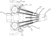
- FIG. 1 is a schematic view showing the overall structure of a minimally invasive surgical device based on a natural cavity according to an embodiment of the present disclosure
- FIG. 2A is a schematic view showing the overall structure of a control box assembly in a minimally invasive surgical device based on a natural cavity according to an embodiment of the present disclosure
- FIG. 2B is a schematic view showing the internal structure of the control box assembly shown in FIG. 2A;
- FIG. 2C is a schematic diagram of a triangular drive assembly of the control box assembly shown in FIG. 2A;
- FIG. 2D is a schematic structural view of a rotary switch of the control box assembly shown in FIG. 2A;
- FIG. 2E is a schematic structural view of a quick change device of the control box assembly shown in FIG. 2A;
- 3A is a schematic structural view of a tip assembly of a minimally invasive surgical device based on a natural cavity according to an embodiment of the present disclosure
- FIG. 3B is a schematic view showing the structure of the opening and closing body of the end assembly shown in FIG. 3A;
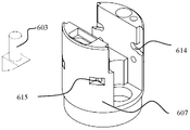
- FIG. 3C is a schematic structural view of the end body of the end assembly shown in FIG. 3A;
- 3D is a schematic diagram of an initial posture of the tip assembly shown in FIG. 3A;
- FIG. 3E is a schematic enlarged view of the operation of the end assembly shown in FIG. 3A; FIG.
- FIG. 4 is a schematic structural view of a hose assembly in a minimally invasive surgical device based on a natural cavity according to an embodiment of the present disclosure
- FIG. 5 is a schematic structural view of a surgical tool installed on a minimally invasive surgical device based on a natural cavity according to an embodiment of the present disclosure
- FIG. 6 is a schematic diagram of a gastric surgery of a minimally invasive surgical device based on a natural cavity according to an embodiment of the present disclosure.
- FIG. 1 is a schematic view of an overall structure of a minimally invasive surgical device based on a natural cavity according to an embodiment of the present disclosure, which includes a control box assembly 300 in which a hose assembly 400 is fixedly connected in the middle of a front end of the control box assembly 300, and is disposed.
- the serpentine structure 500 and the tip assembly 600 inside the hose assembly 400, the hose assembly 400, the serpentine structure 500 coincides with the axis of the tip assembly 600, and the left and right surgical tools 100, 200 and the control box assembly
- the back end of the 300 is connected.
- the control box assembly 300 is a manipulation component of a natural-channel minimally invasive surgical device.
- the control box assembly 300 can include a front cover assembly 101, the front cover The rear end of the assembly 101 is fixedly coupled to the front end of the control box housing 107.
- the front cover assembly 101 provides access to the surgical tools 100 and 200, and also provides access to the transmission wire for controlling the control assembly 300, requiring a certain rigidity.
- the front cover assembly 101 plays an important connecting role.
- the front end of the front cover assembly 101 is sequentially coupled to the serpentine structure 500 and the tip assembly 600 by a hose assembly 400.
- the control box housing 107 may specifically include a lower housing and an upper housing fixed to the lower housing.
- a fixing plate 113 may be fixed by a pin, and the two structures are the same.
- the tool tube 114 is symmetrically fixed to the fixed plate 113 by a pressing block 115.
- the front ends of the two tool tubes 114 are disposed in the front sleeve assembly 101, and the tool tube 114 serves as a passage through the surgical tool.
- the partition 112 may be fixed to the fixing plate 113 by a pin, and the chute 110 may be fixedly coupled to the partition 112 by a pin.
- control box assembly 300 can further include a delta drive assembly 102 coupled between the diaphragms 112 and including a cap 201 that the physician can operate by operating the cap 201 to effect movement of the tip assembly 600 of the front end.
- the triangular drive assembly 102 can include a toggle lever 202 disposed through the middle of the upper housing, and a cap 201 is coupled to the top of the toggle lever 202 by a key.
- the cap 201 is a manually operated object, and the pull-back lever 202 can be pulled back and forth.
- the rear end of the bottom of the toggle lever 202 is rotatably connected to the fixing frame 203 by a connecting pin, so that the rotation around the connecting pin can be realized.
- the front end of the bottom of the toggle lever 202 is rotatably connected to the rear end of a pull rod 207 by a connecting pin.
- the front end of the pull rod 207 is connected to the sliding block 204 by a pin rotation.
- the sliding block 204 and the fixed frame are fixed.
- the 203 is slidably coupled by the rail slider structure, whereby the rotational movement of the toggle lever 202 can be converted into a linear motion of the slider 204, the holder 203 is fixed to the partition 112, and the rear end of the spring 205 is fixed to the slider
- the front end of the 204 is fixed to the front wall of the fixing frame 203, the sliding axis of the sliding block 204 coincides with the axis of the rail of the fixing frame 203, and one end of the linear driving wire 117 is fixedly connected with one end of the wire joint 206.
- the other end of the linear drive wire 117 passes through the front sleeve assembly 101, the guide wire hole on the connecting ring 702 of the hose assembly 400, and the serpentine structure 500, and is then attached to the drawn wire 609 of the end assembly 600. .
- the spring 205 is elongated in a normal state such that the sliding block 204 is close to the toggle lever 202, keeping the sliding block 204 normally away from the front wall of the fixing frame 203; pressing the toggle lever 202 downwardly compresses the spring 205, when loose Opening the toggle lever 202, the toggle lever 202 is restored to the original position due to the elastic force of the spring 205, and a cylindrical hole is formed in the front wall of the fixing bracket 203, and the rear end of a triangular wire connector 206 passes through the The cylindrical hole and the spring 205 are fixedly connected to the sliding block 204.
- the axis of the triangular wire connector 206 coincides with the sliding axis of the sliding block 204, and the toggle lever 202 is manually pulled to drive the movement of the pull rod 207.
- the pull rod 207 is connected to one end of the sliding block 204.
- the linear motion of the slider 204 drives the movement of the wire joint 206.
- the control box assembly 300 further includes two rotary switches 104, respectively disposed symmetrically on the rear side of the partition 112, which is a transmission component of the minimally invasive surgical control box, two rotations.
- the switch 104 has the same structure.
- Each of the rotary switches 104 includes a swinging rod 402 and a threaded frame 403.
- a swinging wheel 401 is fixed on the top of the swinging rod 402, and a central hole is formed in the top wall of the threaded frame 403.
- a cavity communicating with the central hole is disposed in the middle of the threaded frame 403, and a lower portion of the swinging rod 402 passes through a central hole of the threaded frame 403 and extends into the cavity, the swinging
- the rod 402 is clearance-fitted with the central hole of the turret 403, and an external gear 302 is fixed to the bottom of the swinging rod 402 located in the turret 403, and an upper magnet group is fixed on the bottom wall of the external gear 302.
- the threaded frame 403 is fixed on the threaded seat 404, and the threaded seat 404 is fixed on the fixing plate 113 by a fixing bolt 405, and an inner ring gear 301 is fixed in the threaded frame 403.
- a lower magnet assembly 409 is fixed to the bottom inner wall of the threaded seat 404 opposite to the upper magnet assembly 408.
- the outer gear 302 is supported on a thrust spring 407, and the upper magnet assembly 408 is wrapped around the thrust spring.
- 407 in the normal state, that is, the spring non-stress state, the upper end of the thrust spring 407 is in contact with the lower end of the external gear 302, and the lower end of the thrust spring 407 is fixedly connected to the lower magnet assembly 409, and is located at the lower portion of the inner ring gear 301.
- the outer sleeve of the thrust spring 407 has a compression washer 406 to fix the radial position of the thrust spring 407, and the limit is fixed.
- the axis of the inner ring gear 301 and the outer gear 302 and the axis of the swing rod 402 can be moved up and down to drive the inner ring gear 301 to engage or disengage with the external gear 302.
- the swinging rod 402 is mounted on the swinging rod 402 located at the upper portion of the threaded frame, and the left and right sides are chain 103 the same structure.
- the thrust spring 407 is extended, and the outer gear 302 is brought close to the upper end surface of the inner wall of the crease 403 by the extension force of the spring, and the outer gear 302 and the inner ring gear 301 are not engaged.
- the oscillating wheel 401 drives the oscillating lever 402 to perform a rotational motion, thereby driving the external gear 302 to rotate.
- the outer gear 302 and the upper magnet assembly 408 move downward with the swing wheel 401, and the outer gear 302 moves downward to squeeze the thrust spring 407 so that the thrust spring 407 is in a compressed state, and the upper magnet assembly 408 is
- the external gear 302 meshes with the inner ring gear 301 in the same plane, and the inner ring gear 301 and the outer gear 302 rub.
- the contact makes the oscillating wheel unable to rotate, thereby realizing the locking of the control box.
- the threaded frame 403 has a certain fixing effect on the swinging rod 402 in the axial direction.
- the swinging wheel 401 is manually pulled upward, the distance between the upper magnet assembly 408 and the lower magnet assembly 409 becomes larger, and the attraction between the magnet assemblies is smaller than that of the thrust spring 407.
- the extension force under the action of the extension force of the thrust spring 407, the external gear 302 moves upwardly out of engagement with the ring gear 301 to unlock the surgical control box, and the swing rod 402 continues to move upward to return to the initial state, the external gear 302 It is in contact with the upper end of the ferrule 403, thereby realizing a non-linear action switch.
- Each of the sets of the chutes 110 includes Two spacer grooves 110 are provided at intervals, and the sprocket 103 on each of the swinging rods 402 is respectively engaged with a chain 111 wound around the sprocket 103, and the two free ends of each of the chains 111 are respectively Separately disposed in the two chutes 110 of the plurality of chutes 110, the chain 111 can be reciprocally linearly moved in the chute 110 by the swinging rod 402, and each of the chains 111 The two free ends are fixedly connected to one end of the transmission wire 116, and the other ends of the four transmission wires 116 sequentially pass through the front sleeve assembly 101, the guide wire hole of the connecting ring 702 and the guide wire on the serpentine structure 500.
- the hole is then fixed in the rear end opening of the end body 607 of the end assembly 600, and the transmission wire 116 reciprocates back and forth in the guide wire hole of the connecting ring 702, and the transmission wire is tensioned and relaxed, thereby making the serpentine structure 500 Flexing movement under the pulling action of the transmission wire to realize the front end hose assembly 400 For, so that the operation of the front end of the surgical device pitching motion, swing.
- the connection of the transmission wire 116 to the serpentine structure 500 can be performed by using the existing structure, and the transmission wire 116 can slide in the guide wire hole.
- the rotary switch 104 is manually operated to rotate about the axis, thereby driving the sprocket 103 to rotate, so that the chain 111 fixedly connected to the sprocket 103 linearly moves, and the linear motion of the chain 111 drives the transmission wire 116 to slide in the guide wire hole.
- the linear motion of the drive wire 116 drives the movement of the serpentine structure 500 of the surgical device to achieve the desired surgical channel configuration.
- the rotary switch 104 is manually operated to drive the linear tensioning movement of the transmission wire 116 to achieve upward or downward bending of the front end serpentine structure 500, swinging to the left and right, thereby enabling the placement of the surgical device.
- the adjustment of the two sets of gears achieves the locking of the up and down pitch and the left and right swing positions of the front end of the serpentine structure 500 of the surgical device, and the movement of the up and down pitch and the left and right swings can be realized.
- the wire rope connection structure disclosed in CN200910306053.5 Thereby, the reach of the surgical device can be expanded.
- the left and right quick change devices 105 are important components for minimally invasive surgery, and are disposed on the left and right sides of the rear wall of the lower casing of the control box housing 107, respectively.
- Two quick-change devices 105, the two quick-change devices 105 include two lower connecting sleeves 501 fixedly connected to the left and right sides of the lower casing of the lower casing of the control box casing 107, and each of the lower connecting sleeves 501 The front end is fixedly connected to the rear end of the tool tube 114 on the corresponding side, and an outer telescopic sleeve 502 is sleeved and fixed on each of the lower connecting sleeves 501.
- the middle telescopic sleeve 503 is slidably inserted into the middle hole of the outer telescopic sleeve 502.
- the inner telescopic sleeve 504 is slidably inserted into the middle hole of the middle telescopic sleeve 503, and an upper connecting sleeve 506 is fixed at the rear end of the inner telescopic sleeve 504, and the upper connecting sleeve 506 is disposed on both sides of the axis of the upper connecting sleeve 506.
- Two rectangular slots of the same structure are symmetrically opened, and the two unlocking levers 507 having the same structure each include a straight rod section which is clearance-fitted in a rectangular slot of the corresponding side, and the rear end of the straight section is provided with a groove on the surgical tool is hooked and fitted with a pressing hook, and a pressing plate is connected to the front end of the straight rod segment, and the straight rod segment of the two unlocking rods 507 is connected with the upper connecting sleeve 506 through the rotating shaft, in each The upper connecting sleeve 506 portion of the pressing plate is respectively arranged to pass the bomb A plunger 505 is fixedly connected.
- the pressing plate can be in contact with the top of the jack 505.
- the surgical tool If the surgical tool is inserted from the upper connecting sleeve 506 of the quick change device 105, the surgical tool passes through the intermediate hole of the inner telescopic sleeve 504, and is placed in the quick change device 105, the front end of the rod end of the unlocking rod 507 is squeezed by friction, The groove on the surgical tool cooperates with the hook of the unlocking lever 507, and the front end of the unlocking lever 507 is biased to act on the pressing plate at the rear end of the unlocking lever 507, and is in contact with the jack 505, so that the front end of the unlocking lever 507 is opened.
- a water gas switch 106 can be connected to the upper casing for easy operation by a doctor, the water gas switch 106 is connected to the water pipe to access the water source, and the water gas switch 106 can be opened to clean the lens.
- the doctor who is undergoing surgery has a wide field of vision and can clean the surface of the human organ. During the operation, there may be bleeding. At this time, the water-to-air switch 106 is activated to clean the organs around the surgery, which can improve the doctor's surgery. Security.
- the water gas switch 106 can be constructed in the prior art.
- the tip assembly 600 provides a support channel for a minimally invasive surgical instrument end effector, and the tip assembly 600 effects the connection of the surgical tool end effector to the hose assembly 400 of the surgical device, the end
- the head assembly 600 includes a tip body 607 and an opening and closing body installed in an intermediate slot of the tip body 607, the opening body comprising two triangular rings 601 of the same structure and symmetrically disposed on the left and right sides, in the two triangles
- An intermediate position between the rings 601 is provided with a triangular pull rod 610, and a cylindrical boss 612 and a cylindrical hole 613 are symmetrically disposed on each side of each of the triangular rings 601, and the axis of the cylindrical boss 612 is symmetrical.
- each of the bosses 612 is rotatably connected to one end of one of the links 602, and the other end of the two links 602 on the front side and the two sides of the rear side are connected
- the other end of the rod 602 is rotatably connected to the front and rear ends of the triangular rod 610 by a pin 611, and the front end of the drawn wire 609 is vertically fixedly connected to the triangular rod 610, and a triangular spring is set on the drawn wire 609.
- the rear end of the drawn wire 609 is disposed through an intermediate opening of a tip body 607, and a boss is disposed in the intermediate opening, and the triangular spring 608 is disposed in the middle opening
- the inner and lower ends are fixedly coupled to the boss.
- the upper ends of the triangular springs 608 are in contact with the bottom ends of the triangular rods 610, and each of the cylindrical holes 613 and the cylindrical side of a triangular pin 603 Rotating and the triangular pin 603 is fixed to the end body 607, and the triangular ring 601 is rotatable about the triangular pin 603.
- the triangular pin 603 has a triangular prism structure, and a triangular prism hole 615 is defined in the end body 607, and the triangular prism structure is fixed on the triangular prism hole 615.
- An arcuate groove 614 is disposed on an inner wall of the intermediate end of the end body 607 corresponding to the four cylindrical bosses 612.
- the end portion of the cylindrical boss 612 of the cam ring 601 is slidably disposed in a correspondingly disposed circle.
- the cylindrical boss 612 can slide back and forth in the circular arc groove 614, and the triangular pull rod 610 and the connecting rod 602 are rotatably connected with the triangular pin 603 and the triangular ring 601 to form a common one.
- Four-bar mechanism At the arc groove 614, the cylindrical boss 612 can slide back and forth in the circular arc groove 614, and the triangular pull rod 610 and the connecting rod 602 are rotatably connected with the triangular pin 603 and the triangular ring 601 to form a common one.
- the drawing wire 609 is pulled, and the drawing wire 609 is linearly moved downward to drive the fixed connection to the triangular rod 610 to compress the triangular spring 608 to move downward, and the pulling rod 602 which is rotatably connected with the triangular rod 610 is rotated, and the rotation of the rod 602 is driven.
- the cylindrical boss 612 of the right triangular ring 601 slides in the circular arc groove 614 on the end main body 607, and the triangular ring 601 rotates outwardly around the triangular pin 603. Similarly, the rotation of the pull rod 602 drives the left triangle.
- the ring 601 is rotated outwardly, and the two triangular rings 601 are respectively rotated outward, whereby a large angle is formed between the two triangular rings 601, and the triangular ring 601 of the end assembly 600 based on the front end of the natural lumen surgical device is realized.
- the motion output the initial posture is shown in Fig. 3D, a small angle ⁇ 1 is formed between the left and right triangle rings 601, the triangular driving assembly 102 is manually operated, and the stretching wire 609 is tensioned to reach the posture of Fig. 3E, and the left and right triangle rings
- a large angle ⁇ 2 is formed between 601, and different angular changes are output to achieve the desired surgical position setting.
- the doctor realizes the movement of the tip assembly of the front end by rotating the cap 201 of the operation control box, thereby realizing the expansion of the surgical operation triangle of the surgical device.
- the two surgical tools 100, 200 sequentially pass through the connecting sleeve 506 of the corresponding side, the tool tube 114 of the control box of the corresponding side, the front sleeve assembly 101 of the surgical device, the tool hole of the connecting ring 702 of the hose assembly 400, and the snake bone.
- the structure 500, the rear ends of the two surgical tools 100, 200 are respectively fixed by the concave hooks of the unlocking rods 507, and the end effector of the front end of the surgical tool passes through the surgical tool channel 605, respectively, and the gap is set.
- the end effector of the surgical tool is passively disposed in the corresponding follower cam 601 movement in the cam ring 601.
- the hose assembly 400 provides access to the minimally invasive surgical tool and the drive wire.
- the hose assembly 400 is in direct contact with the natural lumen of the human body and should have good softness and no damage to the natural passage of the human body.
- the hose assembly 400 includes a fixed outer skin 701 that is fixedly coupled to the front sleeve assembly 101.
- the fixed outer skin 701 is a rubber tube, and the front ends of the fixed outer skins 701 are sequentially connected.
- the ring 704 is connected to the outer cover 703.
- the four connecting rings 702 are fixedly disposed inside and behind the fixed outer skin 701. Each of the connecting rings 702 is provided with a plurality of cylindrical guide wire holes and two tool holes.
- the serpentine structure 500 is mounted within the outer sheath 703 with 200 through the tool aperture of the hose assembly 400.
- FIG. 6 is a schematic view showing the application of a minimally invasive surgical device based on a natural cavity in gastric surgery according to an embodiment of the present disclosure.
- the end effector of the surgical tool of the minimally invasive surgical device 1 of the embodiment of the present disclosure extends into the stomach 3 of the human body through the human esophagus 2 for surgical operation, and the end effectors of the surgical tools 100 and 200 directly contact the stomach of the human body.
- the hose assembly 400 of the surgical device Direct contact with the esophagus 2 of the human body.
- the operation of the minimally invasive surgical device based on natural lumens is as follows:
- a minimally invasive surgical device based on a natural cavity the minimally invasive surgical tool is held by a doctor, the doctor firstly properly positions the surgical device, the control box assembly 300 is fixed in position, and the rotary switch 104 is adjusted, left and right Different rotary switches 104 respectively control different actions, one left rotary switch 104 realizes the tilting motion of the serpentine structure 500 of the front end surgical device, and the other rotary switch 104 realizes the left and right swing of the snake bone structure 500. Referring to FIG. 1, the doctor faces up.
- the control box assembly 300 In the surgical control box assembly 300, the control box assembly 300 is normally in an unlocked state, and the left rotary switch 104 is rotated counterclockwise to implement the upward tilting motion of the front end serpentine structure 500, and the rotary switch 104 is pressed downward to implement the surgical control box assembly.
- the locking of the 300, the serpentine structure 500 at the front end of the surgical device maintains the upward tilting motion. If the rotary switch 104 is pulled upward to unlock the control box assembly 300, and the left rotary switch 104 is rotated clockwise, the front end serpentine structure 500 can be realized. The action of going down.
- the control box assembly 300 is in an unlocked state, and the right rotary switch 104 is rotated counterclockwise to realize the leftward swinging motion of the front end snake bone structure 500, and the rotary switch 104 is pressed downward to realize the locking of the surgical control box assembly 300.
- the snake bone structure 500 at the front end of the device maintains the action of swinging to the left. If the rotary switch 104 is pulled upward to unlock the control box assembly 300, and the right rotary switch 104 is rotated clockwise, the rightward swinging motion of the snake bone structure 500 can be realized. At this time, the rotary switch 104 is pressed down to lock the control box assembly 300, and the serpentine structure 500 of the surgical device maintains the action at this time.
- a surgical tool is inserted into the passage of the upper connecting sleeve 506 of the quick change device 105 of the control box assembly 300, and the surgical tool squeezes the straight end of the unlocking rod 507 by friction to make the groove and unlock on the surgical tool
- the male hooks of the rod 507 are mated such that the end effector of the surgical tool sequentially passes through the tool tube 114 of the control box, the front cover assembly 101 of the surgical device, the hose assembly 400, and the serpentine structure 500, the end effector settings of the surgical tool At the tip assembly 600 of the surgical device, wherein the operating handle end of the surgical tool is coupled to the quick change device 105 of the control box by the groove-protrusion hook, thereby allowing the surgical tool operating end to be placed at the rear end of the control box
- the end effector is disposed at the tip assembly 600 of the surgical device, thereby effecting the fixation of the surgical tool, then adjusting the triangular drive assembly 102, manually pulling the toggle lever 202 backward,
- the purpose of the present disclosure is to overcome the shortcomings of the prior art, and to provide a minimally invasive surgical device based on a natural cavity that is small in size, convenient to use, flexible in operation, and large in operation operation.
Landscapes
- Health & Medical Sciences (AREA)
- Surgery (AREA)
- Life Sciences & Earth Sciences (AREA)
- Engineering & Computer Science (AREA)
- Heart & Thoracic Surgery (AREA)
- Nuclear Medicine, Radiotherapy & Molecular Imaging (AREA)
- Biomedical Technology (AREA)
- Medical Informatics (AREA)
- Molecular Biology (AREA)
- Animal Behavior & Ethology (AREA)
- General Health & Medical Sciences (AREA)
- Public Health (AREA)
- Veterinary Medicine (AREA)
- General Engineering & Computer Science (AREA)
- Pathology (AREA)
- Mechanical Engineering (AREA)
- Surgical Instruments (AREA)
Abstract
L'invention concerne un dispositif microchirurgical à base de canal naturel, comprenant : un composant de boîte de commande (300); et un composant de tube souple (400), une structure de tige flexible (500), et un composant d'extrémité (600) relié de manière fixe à une partie centrale avant du composant de boîte de commande (300), dans cet ordre. Le composant de tube souple (400), la structure de tige flexible (500) et le composant d'extrémité (600) ont des axes de chevauchement. Le composant de boîte de commande (300) est utilisé pour positionner et changer un instrument microchirurgical, pour le fonctionnement et le support d'un outil chirurgical (100, 200), et pour la mise en oeuvre d'une procédure microchirurgicale. Le composant de tube souple (400) fournit un canal, une sortie de mouvement et une sortie de charge pour l'instrument microchirurgical et un fil d'acier de transmission (116). Le composant d'extrémité (600) fournit un support pour le fonctionnement d'une extrémité de l'instrument microchirurgical, augmentant une plage de mouvement d'un instrument chirurgical. Le dispositif est facile à utiliser, et fournit un mouvement précis et une opération en temps réel favorable. L'invention permet d'obtenir un objectif de microchirurgie de base, augmente la flexibilité de mouvement et l'espace pour la maniabilité d'un instrument chirurgical, et permet d'effectuer une microchirurgie d'une manière manuelle.
Priority Applications (2)
| Application Number | Priority Date | Filing Date | Title |
|---|---|---|---|
| EP17844969.0A EP3345552B1 (fr) | 2016-08-27 | 2017-06-09 | Dispositif microchirurgical à base de canal naturel |
| US15/765,929 US10702253B2 (en) | 2016-08-27 | 2017-06-09 | Natural orifice translumenal minimally invasive surgical apparatus |
Applications Claiming Priority (2)
| Application Number | Priority Date | Filing Date | Title |
|---|---|---|---|
| CN201610751855.7A CN106264626B (zh) | 2016-08-27 | 2016-08-27 | 一种基于自然腔道的微创手术装置 |
| CN201610751855.7 | 2016-08-27 |
Publications (1)
| Publication Number | Publication Date |
|---|---|
| WO2018040662A1 true WO2018040662A1 (fr) | 2018-03-08 |
Family
ID=57674169
Family Applications (1)
| Application Number | Title | Priority Date | Filing Date |
|---|---|---|---|
| PCT/CN2017/087729 Ceased WO2018040662A1 (fr) | 2016-08-27 | 2017-06-09 | Dispositif microchirurgical à base de canal naturel |
Country Status (4)
| Country | Link |
|---|---|
| US (1) | US10702253B2 (fr) |
| EP (1) | EP3345552B1 (fr) |
| CN (1) | CN106264626B (fr) |
| WO (1) | WO2018040662A1 (fr) |
Cited By (3)
| Publication number | Priority date | Publication date | Assignee | Title |
|---|---|---|---|---|
| CN108742782A (zh) * | 2018-04-09 | 2018-11-06 | 李益香 | 腹腔镜用多功能手术抓钳 |
| CN114869376A (zh) * | 2022-05-09 | 2022-08-09 | 南京鼓楼医院 | 一种胸腔镜下心房缝合器 |
| CN115059856A (zh) * | 2022-06-15 | 2022-09-16 | 郑州郑房测绘有限责任公司 | 一种适用于野外作业的地籍测绘用全站仪 |
Families Citing this family (18)
| Publication number | Priority date | Publication date | Assignee | Title |
|---|---|---|---|---|
| CN106264626B (zh) * | 2016-08-27 | 2018-07-24 | 天津大学 | 一种基于自然腔道的微创手术装置 |
| CN110584788A (zh) * | 2019-10-14 | 2019-12-20 | 山东建筑大学 | 一种四自由度微创手术器械驱动平台 |
| CN112426224B (zh) * | 2020-10-20 | 2022-01-28 | 郑州郅隆智能科技有限公司 | 一种毫米级超自由度精准智能微创设备及系统 |
| CN114366191B (zh) * | 2020-11-26 | 2025-09-12 | 中国人民解放军空军军医大学 | 可调式普胸外科手术用开胸器 |
| CN112244967B (zh) * | 2020-11-30 | 2021-08-03 | 武孟孟 | 一种一次性甲状腺穿刺器定位装置 |
| CN112704524B (zh) * | 2020-12-23 | 2022-07-15 | 王冬 | 一种用于食管与肠道缝合的空肠固定和移动装置 |
| CN113317849B (zh) * | 2021-04-22 | 2022-09-27 | 卫飞 | 一种骨穿刺针发射装置 |
| CN113425343B (zh) * | 2021-07-02 | 2022-10-04 | 西安交通大学医学院第一附属医院 | 一种神经内镜立体定向手术辅助通道设备 |
| CN113476144B (zh) * | 2021-08-23 | 2022-08-05 | 上海生知医疗科技有限公司 | 一种多自由度的便携微创手术机械臂 |
| CN114533271B (zh) * | 2021-09-13 | 2023-10-31 | 广西大学 | 一种单孔微创手术操控系统 |
| CN114668432B (zh) * | 2022-03-29 | 2024-06-07 | 吉林大学 | 一种经自然腔道诊疗一体式手术机器人 |
| CN114469283B (zh) * | 2022-03-31 | 2022-07-01 | 真健康(北京)医疗科技有限公司 | 连杆式四自由度穿刺针定位导向装置 |
| CN115089266A (zh) * | 2022-06-27 | 2022-09-23 | 张旭光 | 一种带蛇形管机构的手术钳 |
| CN115737067A (zh) * | 2022-11-09 | 2023-03-07 | 上海医疗器械(集团)有限公司手术器械厂 | 应用于可变形腔镜下的荷包成形钳装置 |
| CN115530726A (zh) * | 2022-11-11 | 2022-12-30 | 苏州阿酷育医疗科技有限公司 | 一种腔镜手术组件 |
| CN116269655B (zh) * | 2022-11-30 | 2025-08-26 | 邦尼医疗科技(常州)有限公司 | 手术器械终端工具双向差动装置 |
| CN116211392A (zh) * | 2023-01-20 | 2023-06-06 | 骨圣元化机器人(深圳)有限公司 | 骨锉转接装置及医疗设备 |
| CN116327280B (zh) * | 2023-04-26 | 2025-09-05 | 武汉米隽医疗器械有限公司 | 一种手术用拉钩 |
Citations (8)
| Publication number | Priority date | Publication date | Assignee | Title |
|---|---|---|---|---|
| JPH08224248A (ja) * | 1995-02-23 | 1996-09-03 | Olympus Optical Co Ltd | 医療用マニピュレータ |
| US5860995A (en) * | 1995-09-22 | 1999-01-19 | Misener Medical Co. Inc. | Laparoscopic endoscopic surgical instrument |
| CN101637402A (zh) * | 2009-10-23 | 2010-02-03 | 天津大学 | 一种微创外科丝传动、四自由度手术工具 |
| US20110130787A1 (en) * | 2008-07-29 | 2011-06-02 | Universite Joseph Fourier-Grenoble 1 | Modular surgical tool |
| CN102309363A (zh) * | 2010-06-29 | 2012-01-11 | 王东 | 一种综合内窥镜手术平台 |
| CN103110455A (zh) * | 2012-12-18 | 2013-05-22 | 杭州好克光电仪器有限公司 | 一种输尿管镜 |
| CN105796138A (zh) * | 2016-05-11 | 2016-07-27 | 天津大学 | 基于自然腔道的柔性微创手术器械 |
| CN106264626A (zh) * | 2016-08-27 | 2017-01-04 | 天津大学 | 一种基于自然腔道的微创手术装置 |
Family Cites Families (9)
| Publication number | Priority date | Publication date | Assignee | Title |
|---|---|---|---|---|
| US6352503B1 (en) * | 1998-07-17 | 2002-03-05 | Olympus Optical Co., Ltd. | Endoscopic surgery apparatus |
| US8518024B2 (en) * | 2006-04-24 | 2013-08-27 | Transenterix, Inc. | System and method for multi-instrument surgical access using a single access port |
| US8715270B2 (en) * | 2006-12-01 | 2014-05-06 | Boston Scientific Scimed, Inc. | Multi-part instrument systems and methods |
| US8591399B2 (en) | 2007-04-25 | 2013-11-26 | Karl Storz Endovision, Inc. | Surgical method utilizing transluminal endoscope and instruments |
| US20110230723A1 (en) | 2008-12-29 | 2011-09-22 | Salvatore Castro | Active Instrument Port System for Minimally-Invasive Surgical Procedures |
| US20100286478A1 (en) * | 2009-04-23 | 2010-11-11 | Usgi Medical, Inc. | Flexible surgery access systems |
| US9797486B2 (en) | 2013-06-20 | 2017-10-24 | Covidien Lp | Adapter direct drive with manual retraction, lockout and connection mechanisms |
| US10258363B2 (en) * | 2014-04-22 | 2019-04-16 | Ethicon Llc | Method of operating an articulating ultrasonic surgical instrument |
| CN106361383B (zh) | 2016-08-27 | 2018-09-25 | 天津大学 | 一种具有锁紧功能的自然腔道微创手术控制器 |
-
2016
- 2016-08-27 CN CN201610751855.7A patent/CN106264626B/zh active Active
-
2017
- 2017-06-09 WO PCT/CN2017/087729 patent/WO2018040662A1/fr not_active Ceased
- 2017-06-09 EP EP17844969.0A patent/EP3345552B1/fr active Active
- 2017-06-09 US US15/765,929 patent/US10702253B2/en active Active
Patent Citations (8)
| Publication number | Priority date | Publication date | Assignee | Title |
|---|---|---|---|---|
| JPH08224248A (ja) * | 1995-02-23 | 1996-09-03 | Olympus Optical Co Ltd | 医療用マニピュレータ |
| US5860995A (en) * | 1995-09-22 | 1999-01-19 | Misener Medical Co. Inc. | Laparoscopic endoscopic surgical instrument |
| US20110130787A1 (en) * | 2008-07-29 | 2011-06-02 | Universite Joseph Fourier-Grenoble 1 | Modular surgical tool |
| CN101637402A (zh) * | 2009-10-23 | 2010-02-03 | 天津大学 | 一种微创外科丝传动、四自由度手术工具 |
| CN102309363A (zh) * | 2010-06-29 | 2012-01-11 | 王东 | 一种综合内窥镜手术平台 |
| CN103110455A (zh) * | 2012-12-18 | 2013-05-22 | 杭州好克光电仪器有限公司 | 一种输尿管镜 |
| CN105796138A (zh) * | 2016-05-11 | 2016-07-27 | 天津大学 | 基于自然腔道的柔性微创手术器械 |
| CN106264626A (zh) * | 2016-08-27 | 2017-01-04 | 天津大学 | 一种基于自然腔道的微创手术装置 |
Cited By (4)
| Publication number | Priority date | Publication date | Assignee | Title |
|---|---|---|---|---|
| CN108742782A (zh) * | 2018-04-09 | 2018-11-06 | 李益香 | 腹腔镜用多功能手术抓钳 |
| CN114869376A (zh) * | 2022-05-09 | 2022-08-09 | 南京鼓楼医院 | 一种胸腔镜下心房缝合器 |
| CN115059856A (zh) * | 2022-06-15 | 2022-09-16 | 郑州郑房测绘有限责任公司 | 一种适用于野外作业的地籍测绘用全站仪 |
| CN115059856B (zh) * | 2022-06-15 | 2024-01-12 | 郑州郑房测绘有限责任公司 | 一种适用于野外作业的地籍测绘用全站仪 |
Also Published As
| Publication number | Publication date |
|---|---|
| EP3345552A1 (fr) | 2018-07-11 |
| EP3345552B1 (fr) | 2020-05-13 |
| US20180280010A1 (en) | 2018-10-04 |
| EP3345552A4 (fr) | 2019-04-24 |
| CN106264626A (zh) | 2017-01-04 |
| US10702253B2 (en) | 2020-07-07 |
| CN106264626B (zh) | 2018-07-24 |
Similar Documents
| Publication | Publication Date | Title |
|---|---|---|
| WO2018040662A1 (fr) | Dispositif microchirurgical à base de canal naturel | |
| KR101075294B1 (ko) | 최소 침습 수술 기구 | |
| CN101677817B (zh) | 用于不同针的可替换尖端缝合装置和系统 | |
| CN101938946B (zh) | 用于铰接腹腔镜握持仪器的腕部的方法和器械 | |
| CN106419972B (zh) | 可调节夹持力度的可弯曲微创器械 | |
| US20160113732A1 (en) | Surgical tool | |
| CN110236613B (zh) | 腔内手术器械 | |
| JP2015080556A (ja) | 高機能手術デバイス | |
| CN106377315B (zh) | 一种采用无菌屏障的柔性手术工具系统 | |
| CN208725874U (zh) | 一种仿生手术器械和仿生手术器械套件 | |
| CN106361383B (zh) | 一种具有锁紧功能的自然腔道微创手术控制器 | |
| EP4640164A1 (fr) | Dispositif de suture électrique | |
| CN103070707A (zh) | 具有自动换针功能的医用缝合器 | |
| CN114533159B (zh) | 一种缓冲驱动装置及电动缝合器 | |
| CN109770975B (zh) | 一种用于腹腔镜手术的牵拉夹 | |
| CN217408875U (zh) | 一种缓冲驱动装置及电动缝合器 | |
| CN108685604A (zh) | 微创手术器械 | |
| KR101336381B1 (ko) | 최소 침습 수술 기구 | |
| US12496083B2 (en) | Attachment assembly, control handle, series motion mechanism, and minimally invasive surgical instrument | |
| CN107536641B (zh) | 一种可远端操作的外科手术电凝钳 | |
| CN109925060A (zh) | 一种仿生手术器械及其控制方法 | |
| CN106361384B (zh) | 一种基于自然腔道的四杆开合运动装置 | |
| CN219021408U (zh) | 一种万向定型分离钳 | |
| CN220713990U (zh) | 一种腔镜用波浪状无损伤乳腺组织钳 | |
| CN106137283B (zh) | 一种具有调节功能的自然腔道器械运动旋转开关 |
Legal Events
| Date | Code | Title | Description |
|---|---|---|---|
| WWE | Wipo information: entry into national phase |
Ref document number: 2017844969 Country of ref document: EP Ref document number: 15765929 Country of ref document: US |
|
| NENP | Non-entry into the national phase |
Ref country code: DE |