WO2018042509A1 - Dispositif d'épissage - Google Patents
Dispositif d'épissage Download PDFInfo
- Publication number
- WO2018042509A1 WO2018042509A1 PCT/JP2016/075292 JP2016075292W WO2018042509A1 WO 2018042509 A1 WO2018042509 A1 WO 2018042509A1 JP 2016075292 W JP2016075292 W JP 2016075292W WO 2018042509 A1 WO2018042509 A1 WO 2018042509A1
- Authority
- WO
- WIPO (PCT)
- Prior art keywords
- tape
- splicing
- carrier
- carrier tapes
- lid
- Prior art date
- Legal status (The legal status is an assumption and is not a legal conclusion. Google has not performed a legal analysis and makes no representation as to the accuracy of the status listed.)
- Ceased
Links
Images









Classifications
-
- H—ELECTRICITY
- H05—ELECTRIC TECHNIQUES NOT OTHERWISE PROVIDED FOR
- H05K—PRINTED CIRCUITS; CASINGS OR CONSTRUCTIONAL DETAILS OF ELECTRIC APPARATUS; MANUFACTURE OF ASSEMBLAGES OF ELECTRICAL COMPONENTS
- H05K13/00—Apparatus or processes specially adapted for manufacturing or adjusting assemblages of electric components
- H05K13/02—Feeding of components
Definitions
- the present invention relates to a splicing device that automatically connects two carrier tapes, and more particularly to a splicing device that allows a carrier tape that has been spliced to be accurately taken out from the device.
- a carrier tape holding a plurality of electronic components at regular intervals is wound around a reel, and the carrier tape is fixed by driving a sprocket that engages a feed hole drilled in the carrier tape.
- the electronic components are fed to the component supply position.
- the electronic component supplied to the component supply position is sucked by a suction nozzle and mounted on a circuit board.
- the front side (top tape side) and the back side (tape body side) of the two carrier tapes are connected to each other by a splicing tape.
- the splicing tape since the splicing tape is in a state of being adhered to the protective tape, when the carrier tape connected by the splicing tape is taken out, if the carrier tape is not lifted carefully, the carrier force is applied by the adhesive force between the splicing tape and the protective tape. There is a possibility that the splicing tape adhered to the tape may be peeled off.
- An object of the present invention is to provide a splicing device that automatically connects two carrier tapes and can accurately take out a carrier tape that has been spliced from the inside of the device.
- the present invention is a splicing device that connects a first carrier tape and a second carrier tape, each having a feed hole and a component storage cavity, at a predetermined interval, by a splicing tape.
- a positioning device for positioning at a splicing position, and affixed to a protective tape sent in a direction perpendicular to the feeding direction of the first carrier tape and the second carrier tape between the device main body and the lid, A splicing tape positioned at the splicing position, and the splicing tape sent to the splicing position.
- a connecting device for connecting the first carrier tape and the second carrier tape, and a length for peeling the splicing tape from the protective tape by lifting the connected carrier tape connected by the splicing tape from both sides of the connecting portion. And a lifting device with a different pair of hooks.
- the splicing tape since the splicing tape is lifted by the pair of hooks having different lengths, the splicing tape can be gradually peeled off from one end side of the protective tape. Will not peel off. Therefore, there is an effect that the carrier tape that has been spliced can be reliably and easily taken out from the apparatus.
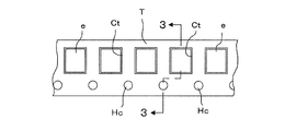
- FIG. 3 is a cross-sectional view taken along line 3-3 in FIG. It is a top view of the carrier tape connected with a splicing apparatus. It is a perspective view which shows the whole splicing apparatus which shows embodiment of this invention. It is a figure which shows the state which opened the cover body of the splicing apparatus. It is a figure which shows the state which mounted
- FIG. 13 is an operation state diagram of FIG. 12 showing a positioning process of a cut portion of the carrier tape.
- FIG. 13 is an operational state diagram of FIG. 12 showing a cutting process of the cut portion of the carrier tape.
- FIG. 13 is an operation state diagram of FIG. 12 showing a positioning process of the carrier tape to the splicing position.
- FIG. 25A is a cross-sectional view taken along the line 25-25 in FIG. 24, and FIGS. 25B and 25C are operation state diagrams of FIG. 25A.
- FIG. 1 shows a tape feeder 10 that is detachably attached to a component supply device of a component mounting machine.
- a reel 12 around which a carrier tape T is wound is detachably attached to the tape feeder 10.
- the carrier tape T is formed to be elongated with a predetermined width, and a large number of cavities Ct are arranged at a constant pitch interval in the longitudinal direction.
- Each component (electronic component) e to be mounted is accommodated.
- the upper portion of the cavity Ct is opened and covered with a top tape Tt that is attached to the surface of the carrier tape T.
- feed holes Hc are formed at the same pitch interval as the cavity Ct or twice the pitch interval of the cavity Ct.
- the feed holes Hc are in a fixed positional relationship with the cavity Ct. Has been placed.
- the tape feeder 10 feeds the carrier tape T wound around the reel 12 quantitatively and feeds the electronic components e one by one to the component supply position 17 provided at the tip of the tape feeder 10. Is built-in.
- the fixed amount feed mechanism 18 is rotatably supported by the main body of the tape feeder 10 and includes a sprocket 19 that engages with the feed hole Hc of the carrier tape T and a motor (not shown) that rotates the sprocket 19 by one pitch. .
- the carrier tape T used in the component mounting machine is composed of a plurality of types having different pitches of the cavities Ct.
- the pitch interval of the cavities Ct and the relationship between the cavities Ct and the feed holes Hc are determined depending on the type of the carrier tape T. Yes. Therefore, by recognizing the pitch interval of the cavities Ct by image processing or the like, it is possible to grasp which type of carrier tape T, and based on that, the position of the feed hole Hc of the carrier tape T can be recognized, The cutting position of the carrier tape T at the time of splicing described later can be determined.
- the splicing device 20 automatically sets the end portion of the carrier tape wound around the current reel attached to the tape feeder 10 attached to the component supply device to the beginning end portion of the carrier tape wound around the next reel to be replaced. Device to connect automatically.
- the splicing device 20 is supported by the device main body 21 and the device main body 21 so as to be rotatable about a pivot 23 (see FIG. 21), and opens and closes the upper surface of the device main body 21.
- a lid 22 which is configured to be movable between tape feeders 10 mounted on a component supply device of a component mounter mounted on an unillustrated cart or the like.
- the lid 22 is manually closed at the time of splicing, and is automatically opened at the time of taking out the carrier tape T after the splicing. Note that once the lid body 22 is closed, the lid body 22 is held in a closed state by a closing holding device described later.
- two carrier tapes T (hereinafter referred to as a first carrier tape T1 and a second carrier tape T2) that are spliced by the splicing device 20 are the same as the first component e1 (second component e2). ) are accommodated at a predetermined pitch Pc (second cavity Ct2).
- first and second carrier tapes T1 and T2 mesh with teeth 67a (67b) of a first sprocket 61a (second sprocket 61b) of a first tape feeder 50 (second tape feeder 51) described later.
- Possible first feed holes Hc1 (second feed holes Hc2) are bored at a predetermined pitch Ph in parallel with the first cavities Ct1 (second cavities Ct2).
- the first and second carrier tapes T1 and T2 are cut by the splicing device 20 at the first and second cutting points Q1 and Q2, and connected by a splicing tape 30 described later.
- a first cutting point Q1 for example, a first cavity Ct1 (second cavity Ct2) having a first part e1 (second part e2) and a first part e1 (second part e2).
- An intermediate position with respect to the empty first cavity Ct1 (second cavity Ct2) having no gap is selected.
- the first carrier tape T1 (second carrier tape T2) in which the cut first empty cavities Ct1 (second cavities Ct2) are continuous is discarded as the first unnecessary portion Tf1 (second unnecessary portion Tf2).
- first unnecessary portion Tf1 second unnecessary portion Tf2
- adjacent empty first cavities Ct1 second cavities Ct2 as first cutting points Q1 (second cutting points Q2)
- the intermediate position can also be selected.
- Two carrier tapes T1 and T2 to be spliced are fed into the splicing device 20 from the left and right in FIG. 6, and the splicing tape 30 connecting the two carrier tapes T1 and T2 from the upper direction in FIG.
- a protective tape 31 (see FIG. 7) to which is attached is sent.
- the ends of the two carrier tapes T ⁇ b> 1 and T ⁇ b> 2 are connected to each other by the splicing tape 30 at the splicing position LS where the carrier tapes T ⁇ b> 1 and T ⁇ b> 2 and the protective tape 31 intersect. ing.
- the splicing tape 30 affixed to the protective tape 31 is sent to the splicing position LS with the adhesive surfaces with the carrier tapes T1 and T2 facing upward, and the two carrier tapes T1 and T2 are located above the splicing tape 30. It is designed to be positioned.
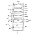
- the splicing tape 30 is a set of splicing for the front and back surfaces that are bonded to both surfaces of the two protective tapes 31 across the upper surface of the continuous protective tape 31. It consists of tapes 30a and 30b. That is, the splicing tape 30 is a set of a front splicing tape 30a connected to the front side of the two carrier tapes T1 and T2 and a back splicing tape 30b connected to the back side of the two carrier tapes T1 and T2. It is what.
- a set of splicing tapes 30 for the front surface and the back surface has a constant pitch in the longitudinal direction of the protective tape 31 while maintaining a fixed positional relationship with the feed holes 31a drilled at a constant pitch interval on both sides of the protective tape 31. Affixed with an interval Pd. Further, one set of splicing tapes 30a and 30b is arranged with a predetermined interval Pd1 with the front splicing tape 30a on the leading side. And in these 1 set of splicing tapes 30a and 30b, metal powder is embed
- a tape detection sensor 48 for detecting the splicing tapes 30a and 30b is separated from the splicing position LS by a predetermined distance S1 on the front side of the splicing position LS. In place.
- the metal detection sensor 48 detects the end of the splicing tape 30 (for example, the back surface splicing tape 30b) through the detection slit 49, the protective tape is fed from the detection position by the stepping motor 47 of the protective tape feeder 36.
- the splicing tape 30 is positioned at the splicing position LS by controlling the feed of 31 by a predetermined amount S1.
- the upper surfaces of the splicing tapes 30a and 30b form an adhesive surface that is bonded to both surfaces of the two carrier tapes T1 and T2, and a continuous paper mount 32 is bonded to the bonded surface as shown in FIG.
- the three-layer structure of the paper mount 32, the splicing tape 30, and the protective tape 31 is wound around the supply reel 33 in a roll shape.
- the widthwise dimension of the protective tape 31 is larger than the widthwise dimension of the paper mount 32, and both ends of the protective tape 31 in the width direction protrude from both ends of the paper mount 32 in the width direction.
- the width direction dimension of the splicing tape 30 is equal to the width direction dimension of the paper mount 32, and the splicing tape 30 is affixed to the protective tape 31 as one set for the front surface and the back surface inside the feed hole 31a. .
- the protective tape 31 has positioning holes 31b at positions close to the surface splicing tape 30a at the same pitch intervals as the feed holes Hc1 and Hc2 formed in the carrier tapes T1 and T2. Are formed along the width direction. Further, a plurality of positioning holes 30b1 are formed in the back surface splicing tape 30b along the width direction of the protective tape 31 through the protective tape 31 at the same pitch intervals as the feed holes Hc1 and Hc2 formed in the carrier tapes T1 and T2. Has been.
- the feed hole 31a and the positioning hole 31b formed in the protective tape 31 are aligned with the formation of the positioning hole 30b1 in the splicing tape 30b after the splicing tapes 30a and 30b are attached to the protective tape 31 at predetermined positions. Formed by a punching press or the like.
- the splicing device 20 can be rotated by rolling a three-layer structure including the splicing tape 30 in a roll shape on a line crossing the splicing position LS for splicing the two carrier tapes T1 and T2.
- a supply reel 33, a paper board feeding device 35 that feeds the paper board 32 peeled off from the splicing tape 30, and a protective tape feeding device 36 that sends out the protective tape 31 from which the splicing tape 30 has been peeled off are provided.
- the adhesive strength between the paper mount 32 and the protective tape 31 bonded to both surfaces of the splicing tape 30 is stronger than the adhesive strength against the protective tape 31, and the splicing tape 30 is protected even if the paper mount 32 is peeled off from the splicing tape 30.
- the tape 31 is not peeled off.
- the adhesive strength thereof is stronger than the adhesive strength to the protective tape 31, and the protective tape 31 than the splicing tape 30. It is easy to peel off.
- the three-layer structure of the paper mount 32, the splicing tape 30, and the protective tape 31 is mounted on the splicing device 20 while being wound around the supply reel 33, and the tip is pulled out from the supply reel 33. Then, the paper mount 32 is peeled off and folded by the operator, and the paper mount 32 is sent out by the paper mount feeder 35 and discarded in a paper mount storage box (not shown).
- the supply reel 33 is rotatably supported by a support body 38 attached to the apparatus main body 21.
- the support 38 is pressed against the supply reel 33 by a predetermined frictional force generated by a spring force, and the support 38 limits the rotation of the supply reel 33 with respect to the support 38.
- the protective tape 31 is pulled with an acting force that overcomes the frictional force, the supply reel 33 can be rotated with respect to the support 38.
- the protective tape 31 from which the paper mount 32 has been peeled off that is, the protective tape 31 to which a large number of splicing tapes 30 are attached with the adhesive surface facing upward passes through the connecting device 58 described below so as to cross the center of the splicing position LS.
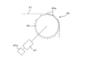
- the front end is engaged with the feed sprocket 46 (see FIG. 10) of the protective tape feeder 36.
- a plurality of engaging teeth 46a are formed on the feed sprocket 46 at equal angular intervals in the circumferential direction at the same pitch as the pitch of the feed holes 31a perforated in the protective tape 31.
- the stepping motor 47 is returned to the origin when the power is turned on, and is positioned so that the engaging teeth 46a of the feed sprocket 46 are always located at the apex. Further, the stepping motor 47 can be appropriately restricted in rotation by, for example, a rotation restricting means 47a such as a servo lock device.
- the carrier tapes T1 and T2 for which splicing has been completed are taken out from the splicing device 20 by the frictional action by the support 38 and the rotation restraint means 47a, the movement of the protective tape 31 at both ends is restricted, and the protective tape 31 It constitutes a blocking device that prevents the buoyancy.
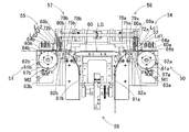
- the splicing device 20 includes first and second tape feeders 50 and 51, first and second component detectors 52 and 53, first and second cutting devices 54 and 55, First and second capture devices 56 and 57, a connection device 58, and a control device 59 (see FIG. 5) are provided.
- the first and second tape feeders 50 and 51, the first and second cutting devices 54 and 55, the first and second take-in devices 56 and 57, the connection device 58 (excluding some) and the control device 59 are:
- the device main body 21 and the lid 22 are housed and arranged.
- first and second tape feeders 50 and 51 are arranged on both sides of the apparatus main body 21 and the lid body 22, respectively. Between, the 1st, 2nd cutting devices 54 and 55 are arranged, respectively. Furthermore, the 1st, 2nd taking-in apparatus 56,57 is each arrange
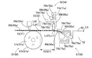
- the first and second component detection devices 52 and 53 are located above the first and second detection positions Ld1 and Ld2 of the first and second transport paths 60a and 60b of the first and second tape feeders 50 and 51, respectively. Is arranged.
- the first and second tape feeders 50 and 51 include first and second transport paths 60a and 60b provided so as to extend in the horizontal direction from both side surfaces of the apparatus body 21 toward the center, and first and second First and second sprockets 61a and 61b disposed below the two transport paths 60a and 60b, first and second stepping motors 62a and 62b connected to the first and second sprockets 61a and 61b, and a first , First and second sprocket tooth detectors 63a and 63b disposed in the vicinity of the second sprockets 61a and 61b, and first and second tape detectors disposed above the first and second transport paths 60a and 60b.
- Devices 64a, 64b, and the like are examples of devices 64a, 64b, and the like.
- the first and second tape feeders 50 and 51 convey the first and second carrier tapes T1 and T2 along the first and second conveyance paths 60a and 60b, respectively.
- the first and second cutting locations Q1 and Q2 (see FIG. 4) of T2 can be sequentially positioned at the first and second cutting positions Lc1 and Lc2 and the splicing position LS.
- the first and second transport paths 60a and 60b have widths slightly wider than the widths of the first and second carrier tapes T1 and T2, and the first and second tape inlets 84a provided on both side surfaces of the apparatus main body 21. , 84b from the first and second cutters 68a and 68b of the first and second cutting devices 54 and 55 to the first and second cutting positions Lc1 and Lc2 of the first and second carrier tapes T1 and T2 extending in a straight line. It is formed in a shape.
- the first and second sprockets 61a and 61b include a plurality of first and second sprockets having the same pitch as the pitch Ph of the first and second feed holes Hc1 and Hc2 drilled in the first and second carrier tapes T1 and T2.
- Two teeth 67a and 67b are formed in the circumferential direction.
- the first and second sprockets 61a and 61b are inserted into the first and second feed holes Hc1 and Hc2 of the first and second carrier tapes T1 and T2 inserted along the first and second transport paths 60a and 60b. It arrange
- the first and second sprocket tooth detectors 63a and 63b are configured to indicate that the first and second sprockets 61a and 61b are in their original positions. Detection is performed by reading the second marks M1 and M2.
- the first and second tape detectors 64a and 64b indicate that the first and second carrier tapes T1 and T2 are inserted from the first and second tape inlets 84a and 84b provided on both side surfaces of the apparatus main body 21, respectively. Detect.
- the first and second component detectors 52 and 53 are the first and second cavities Ct1 and Ct2 of the first and second carrier tapes T1 and T2 that are transported through the first and second transport paths 60a and 60b.
- the tape portion between the second cavities Ct1 and Ct2 and the first and second parts e1 and e2 in the first and second cavities Ct1 and Ct2 are detected.
- the first and second cutting devices 54 and 55 include first and second cutters 68a and 68b provided at the first and second cutting positions Lc1 and Lc2, respectively, First and second cams 69a and 69b slidably contactable with the second cutters 68a and 68b; first and second gear motors 70a and 70b connected to the first and second cams 69a and 69b; The first and second cutter springs 71a and 71b having one end attached to the two cutters 68a and 68b and the other end attached to the lid 22 are provided adjacent to the first and second cutters 68a and 68b.
- the first and second pressing members 72a and 72b and the first and second cutters 68a and 68b are attached at one end and the first and second pressing members 72a and 72b are attached at the other end.
- the first and second cutting devices 54 and 55 use the first and second unnecessary portions Tf1 and Tf2 (see FIG. 14) at the first and second cutting points Q1 and Q2 of the first and second carrier tapes T1 and T2. It is configured to be cuttable.
- the first and second cutters 68a and 68b cut the first and second cutting points Q1 and Q2 of the first and second carrier tapes T1 and T2 positioned at the first and second cutting positions Lc1 and Lc2.
- the first and second cams 69a and 69b are rotated up and down.
- the first and second pressing members 72a and 72b are located near the first and second cutting locations Q1 and Q2 of the first and second carrier tapes T1 and T2 positioned at the first and second cutting positions Lc1 and Lc2. In order to press and fix, it is provided so as to be movable in the vertical direction, and is biased downward by the first and second pressing springs 73a and 73b.
- the first and second take-in devices 56 and 57 are provided between the first and second cutting positions Lc1 and Lc2 and the splicing position LS, and are rotatably supported by the first and second fixing members 78a and 78b.
- the first and second intake members 75a and 75b, and the first and second intake member rotating devices 76a and 76b for rotating the first and second intake members 75a and 75b are configured. Is done.
- the first and second take-in devices 56 and 57 are configured to take in the cut first and second unnecessary portions Tf1 and Tf2 of the first and second carrier tapes T1 and T2, respectively.
- the first and second take-in members 75a and 75b have first and second unnecessary portions Tf1 and Tf2 of the first and second carrier tapes T1 and T2 conveyed on the first and second conveyance paths 60a and 60b. Are formed, and first and second ducts 82a and 82b for guiding the first and second unnecessary portions Tf1 and Tf2 to an unillustrated disposal location are formed.
- the first and second take-in members 75a and 75b are held at the original positions indicated by the one-dot chain line in FIG. 12 when taking the first and second unnecessary portions Tf1 and Tf2. Further, when the first and second carrier tapes T1 and T2 are transported to the splicing position LS, as shown by the solid line in FIG. 12, the first and second take-in member rotating devices 76a and 76b are rotated a predetermined angle.
- the first and second movable transport paths 79a and 79b formed on the first and second intake members 75a and 75b are aligned with the first and second transport paths 60a and 60b.
- the connecting device 58 is provided between the first cutting device 54 and the second cutting device 55.
- the connecting device 58 splices the first and second carrier tapes T1 and T2 with which the first and second cutting points Q1 and Q2 are abutted at the intermediate splicing position LS between the first and second transport paths 60a and 60b.
- the tape 30 can be connected.
- the connection device 58 includes a first elevator 91, a holding plate 97, a second elevator 101, a swivel 103, and the like.
- the first elevator 91 is guided and supported by the main body 21 so that the legs 92 can be raised and lowered.
- the positioning holes 30b1 formed in the splicing tape 30b and the two carrier tapes T1 and T2 are arranged on both sides around the connection position (butting position) of the two carrier tapes T1 and T2.
- Two first positioning pins 93, 94 each engaging with the feed hole Hc are provided so as to project along the feed direction of the carrier tapes T1, T2.
- Each pitch of these two sets of first positioning pins 93 and 94 is determined to be twice the pitch Ph of the feed holes Hc of the carrier tapes T1 and T2.
- pin holes 95 are formed between the first positioning pins 93 and 94 in the first lifting platform 91, and second positioning pins 105 on the swivel base 103 side which will be described later enter into these pin holes 95. It is possible.
- a movable base 96 is movably guided and supported on the apparatus main body 21 in a horizontal direction perpendicular to the longitudinal direction of the carrier tapes T1 and T2, and the movable base 96 is positioned above the first positioning pins 93 and 94.
- a holding plate 97 is attached.
- a U-shaped groove 98 that can accommodate the first positioning pins 93 and 94 is formed at the tip of the pressing plate 97, and the pressing plate 97 has a retracted end from which the groove 98 is separated from the first positioning pins 93 and 94, The groove 98 can be moved forward and backward from the forward end position in which the first positioning pins 93 and 94 are accommodated.
- the leg portion 102 of the second lifting platform 101 is supported and supported by the apparatus main body 21 so as to be movable up and down.
- a swivel 103 is supported at both ends so that it can turn 180 degrees around a pivot shaft 104 parallel to the longitudinal direction of the carrier tapes T1 and T2.
- the swivel base 103 is provided with a pressing plate 103a at a position offset from the turning center, and a plurality of second positioning pins 105 and pin holes 106 are provided on the pressing plate 103a.
- the second positioning pins 105 are arranged at corresponding positions between the first positioning pins 93 and 94 provided on the first lifting platform 91 and can enter the pin holes 95 provided on the first lifting platform 91. It has become.
- the pin holes 106 are arranged at corresponding positions between the second positioning pins 105, and the first positioning pins 93 and 94 provided on the first lifting platform 91 can enter.
- the second positioning pin 105 is engaged with the two carrier tapes T1 and T2 that are positioned at the splicing position LS and the positioning hole 30b1 of the splicing tape 30b by being rotated by 180 degrees of the swivel base 103, and the two carriers.
- the positional relationship between the three of the tapes T1 and T2 and the splicing tape 30 connecting the tapes T1 and T2 is kept constant.
- a pinion 107 is attached to the pivot shaft 104 of the swivel base 103, and a rack 108 that meshes with the pinion 107 is attached to a movable base 109 that is movable in a horizontal direction perpendicular to the conveying direction of the carrier tapes T1 and T2. .
- the swivel base 103 is swung by a rack and pinion mechanism including the pinion 107 and the rack 108.
- the turntable 103 By such turning of the turntable 103, the three carrier tapes T1 and T2 and the splicing tape 30 are sandwiched between the pressing plate 103a and the first lifting table 91 and are connected to each other.
- a cam drum 110 is supported on the apparatus main body 21 so as to be rotatable around an axis parallel to the turning center of the swivel base 103, and is rotated at a low speed in a fixed direction by a drive motor (not shown).
- Two cam grooves 110 a, 110 b, 110 c, and 110 d are formed on both surfaces of the cam drum 110 so as to be endless in the circumferential direction.
- the splicing device 20 is provided with a closing holding device 24 that holds the lid 22 in the closed state during the splicing operation.
- the closing holding device 24 is installed in the apparatus main body 21, and is supported by the apparatus main body 21 so as to be rotatable about the support shaft 26.
- the hook 27 and the engagement pin 28 which are provided so as to protrude downward from the lid body 22 and detachably engage with the hook 27 are mainly configured.
- An opening spring 29 that biases the lid body 22 in the opening direction is provided between the apparatus main body 21 and the lid body 22.
- the opening spring 29 constitutes an opening operation device that operates the lid 22 in the opening direction when the closing holding device 24 is released.
- the lid 22 is provided with a dog, and a closing confirmation sensor operated by the dog is provided in the apparatus main body 21.
- the closing confirmation sensor is operated by a dog when the lid body 22 is closed, and it is confirmed that the lid body 22 is closed based on an ON signal of the closing confirmation sensor.
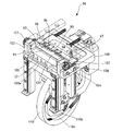
- a lifting device 120 for lifting the first and second carrier tapes T1 and T2 connected by the splicing tape 30 is integrated with the inner surface (lower surface) of the lid body 22 in conjunction with the opening of the lid body 22. Provided. With this lifting device 120, the splicing tape 30 adhered to the protective tape 31 can be accurately peeled off from the protective tape 31.
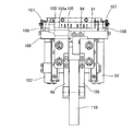
- the lifting device 120 includes a support member 121 fixed to a mounting portion 22a provided on the inner surface of the lid 22, and carrier tapes T1 and T2 are provided at the tip of the support member 121.
- a plate-like lifting arm 122 extending in the longitudinal direction is fixed. Both ends of the lifting arm 122 are bent to form a pair of hooks 123 and 124 having different lengths spaced in the longitudinal direction of the carrier tapes T1 and T2.
- the pair of hooks 123 and 124 is a receiving portion 123a for lifting the first and second carrier tapes T1 and T2 connected by the splicing tape 30 from below at positions close to both ends of the protective tape 31 (splicing tape 30). , 124a are formed.
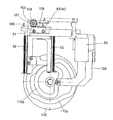
- the receiving portions 123a and 124a of the pair of hooks 123 and 124 are positioned below the extended lines of the transport paths 60a and 60b of the carrier tapes T1 and T2, as shown by the solid lines in FIG.
- the lid 22 When the lid 22 is opened, as shown by a two-dot chain line in FIG. 22, the lid 22 is configured to be positioned above the extended line of the transport paths 60a and 60b.
- the lifting arm 122 is integrally rotated with the lid body 22 around the pivot 23, and the receiving portions 123a and 124a of the pair of hooks 123 and 124 are By traversing the first and second carrier tapes T1 and T2 connected by the splicing tape 30, the carrier tapes T1 and T2 are lifted by being caught by the receiving portions 123a and 124a, and the splicing tape 30 is peeled off from the protective tape 31.
- the carrier tapes T1 and T2 are gradually lifted from the back side in the width direction on the T2 side. It is gradually peeled off from one end (back side) in the width direction on the side. Therefore, when the splicing tape 30 is peeled off from the protective tape 31, the splicing tape 30 is not peeled off from the carrier tapes T1 and T2, and the carrier tapes T1 and T2 can be accurately connected by the splicing tape 30. .
- the operation of the splicing device 20 in the above-described embodiment will be described.
- the remaining amount of the component e held on the first carrier tape T1 wound on the reel 12 attached to the tape feeder 10 decreases, another component e containing the same type of component e is accommodated at the terminal portion of the first carrier tape T1.
- Splicing processing is performed in which the start end portion of the second carrier tape T2 wound around the reel is connected by the splicing tape 30. Parts are supplied by such splicing so that the parts can be continuously supplied from the tape feeder 10.
- splicing verification is performed in which it is checked whether or not a carrier tape containing correct components is connected.
- splicing verification the barcode attached to the old reel is read by a barcode reader, and the serial ID of the component accommodated in the old reel is transmitted to the management computer.
- the barcode attached to the new reel is read by the barcode reader, and the serial ID of the component accommodated in the new reel is transmitted to the management computer.
- the database of the management computer Since the database of the management computer stores data regarding parts for each serial ID, it is determined whether the parts accommodated in the two carrier tapes T1 and T2 are of the same type based on the read serial ID. Can be verified. If the part is wrong, a collation error is displayed on the operation panel and notified to the operator, and based on this, the operator redoes splicing.
- each end of the two carrier tapes T1 and T2 is cut with scissors.
- an empty cavity portion in which no parts are accommodated is usually provided at the end of each of the carrier tapes T1 and T2, and this portion is cut by an operator.
- the cut surface is not a mating surface between the two carrier tapes T1 and T2, so that no particular accuracy is required.
- the control device 59 is based on detection signals from the first and second sprocket tooth detection devices 63a and 63b.
- the stepping motors 62a and 62b are returned to their original positions.
- the control device 59 determines that the leading ends of the first and second tapes T2 from the first and second tape inlets 84a and 84b are based on the detection signals from the first and second tape detection devices 64a and 64b. Detects whether it has been inserted or not.
- the stepping motors 62a and 62b are activated to rotate the first and second sprockets 61a and 61b, and to The movable members 77a and 77b of the insertion members 75a and 75b are moved upward.
- the control device 59 first cavities Ct1 and Ct2 in which the components e1 and e2 of the first and second tapes T1 and T2 are empty and The second cavities Ct1 and Ct2 are sequentially detected, and the pitch Pc between the cavities Ct1 and Ct2 is calculated based on the detection of the first and second cavities Ct1 and Ct2.
- the controller 59 determines the first and second tapes T1, T2 from the pitch Pc between the cavities Ct1, Ct2 and the distances D1, D2 between the known detection positions Ld1, Ld2 and the cutting positions Lc1, Lc2.
- the cutting points Q1 and Q2 are calculated.
- the first and second tapes T1 and T2 are moved by the distances D1 and D2, and the unnecessary portions Tf1 and Tf2 are taken into the first and second take-in members 75a and 75b.
- Q1 and Q2 are transported and positioned at the cutting positions Lc1 and Lc2.
- the control device 59 lowers the cutters 68a and 68b together with the pressing members 72a and 72b, and cuts by the pressing members 72a and 72b.
- the vicinity of the cut portions Q1, Q2 of the first and second carrier tapes T1, T2 positioned at the positions Lc1, Lc2 is pressed and fixed.
- the cutters 68a and 68b are lowered to cut the cut portions Q1 and Q2 of the first and second carrier tapes T1 and T2, respectively.
- Unnecessary portions Tf1 and Tf2 of the first and second carrier tapes T1 and T2 are guided and discarded by the ducts 82a and 82b of the intake members 75a and 75b.
- the control device 59 moves the take-in members 75a and 75b downward. Thereafter, the sprockets 61a and 61b are rotated by the stepping motors 62a and 62b, respectively, and the first and second carrier tapes T1 and T2 are moved by the known distances D3 and D4 between the cutting positions Lc1 and Lc2 and the splicing position LS. Each of the first and second carrier tapes T1 and T2 is moved and positioned at the splicing position LS.
- the feed holes Hc1, Hc2 of the first and second carrier tapes T1, T2 are positioned at positions where they can be engaged with the first positioning pins 93, 94 of the connecting device 58 provided at the splicing position LS.
- the first and second carrier tapes T1 and T2 are positioned to the feed holes Hc1 and Hc2 of the first and second carrier tapes T1 and T2, respectively.
- 94 is positioned at a splicing position LS that engages.
- the tips of the first and second carrier tapes T1 and T2 inserted from the first and second tape inlets 84a and 84b are positioned without causing a pitch shift at the splicing position LS.
- the three-layer structure of the paper mount 32, the splicing tape 30 and the protective tape 31 wound around the supply reel 33 is pulled out from the supply reel 33, and the paper mount 32 is peeled off and sent out by the paper mount feed device 35.
- the protective tape 31 to which the splicing tape 30 is attached is sent out by the protective tape feeder 36, and one set of the splicing tape 30 for the front surface and the back surface is conveyed to the splicing position LS.
- the splicing tape 30b for the back surface is fed to a position detected by the tape detection sensor 48, and further fed from that position by a certain distance, so that one set for the front side and the back side
- the splicing tape 30 is fed into the splicing position LS, and the positioning hole 30b1 formed in the back surface splicing tape 30b is positioned at a position where it can be engaged with the first positioning pins 93 and 94 of the connecting device 58 provided at the splicing position LS. (See FIG. 24).
- the first and second carriers are in that state. Wait until the tapes T1 and T2 are positioned at the splicing position LS.
- the cam drum 110 is rotated by a drive motor (not shown). By the rotation of the cam drum 110, first, the first lifting platform 91 is lifted through a first follower roller (not shown) that engages with the first cam groove 110a.
- the first positioning pins 93 and 94 are engaged with the positioning holes 30b1 of the back surface splicing tape 30b and the feed holes Hc of the two carrier tapes T1 and T2, respectively.
- a pressing plate 97 is interposed between the back surface splicing tape 30b and the carrier tapes T1 and T2, so that the carrier tape T1, T2 does not adhere.
- the positional relationship between the three carrier tapes T1 and T2 and the back surface splicing tape 30b bonded to the back surface of the two carrier tapes T1 and T2 is kept constant.
- the movable base 96 is moved in the horizontal direction via a second follower roller (not shown) that engages with the second cam groove 110b, and is interposed between the back surface splicing tape 30b and the carrier tapes T1 and T2.
- the pressing plate 97 is retracted with respect to the first lifting platform 91, and the back surface splicing tape 30b and the carrier tapes T1 and T2 can be bonded.
- the movable table 109 is horizontally moved through a third follower roller (not shown) that engages with the third cam groove 110c, and the movable table 109 is moved horizontally by the rack and pinion mechanism (107, 108).
- 103 is turned clockwise in FIG.
- the swivel base 103 is swung to fold the protective tape 31 engaged with the second positioning pins 105, and the surface splicing tape 30a is positioned above the carrier tapes T1 and T2. Inverted with the adhesive side facing down.
- the protective tape 31 is bent so as to sandwich the carrier tapes T1 and T2, the back surface splicing tape 30b is provided on the back side of the carrier tapes T1 and T2, and the front splicing tape 30a is provided on the front side of the carrier tapes T1 and T2. Be positioned. At this time, the motor of the protective tape feeding device 36 is rotated in the reverse direction, the protective tape 31 is slackened, and the protective tape 31 is allowed to be bent.
- the second lifting platform 101 is lowered via a fourth follower roller (not shown) that engages with the fourth cam groove 110d.
- a fourth follower roller (not shown) that engages with the fourth cam groove 110d.
- the bent protective tape 31 is pressed between the pressing plate 103a of the swivel base 103 and the first lift base 91 with the carrier tapes T1 and T2 being sandwiched by the lowering of the second lift base 101.
- the back surface splicing tape 30b affixed to the protective tape 31 is adhered so as to straddle the back surfaces of the carrier tapes T1 and T2, and the front surface splicing tape 30a is affixed to the surfaces of the carrier tapes T1 and T2.
- Adhering so as to straddle each top tape Tt the terminal end of the first carrier tape T1 and the start end of the second carrier tape T2 are connected to each other. This pressing state is maintained for a certain time (several seconds).
- the splicing tape 30 connects the two carrier tapes T1 and T2 with the carrier tapes T1 and T2 and the splicing tapes 30a and 30b being restrained from being displaced relative to each other by the first and second positioning pins 93, 94, and 105.
- the two carrier tapes T1 and T2 can be accurately connected without causing a pitch shift.
- connection of the two carrier tapes T1 and T2 by the splicing tape 30 is achieved by the rotation of the cam drum 110 by approximately 180 degrees, and the remaining 180 degrees of rotation causes each component member to be moved in the reverse direction as described above. Returned to
- the second elevator 101 is raised, the swivel 103 is raised relative to the first elevator 91, the pressing of the bent protective tape 31 is released, and the second positioning pin 105 is used for the back surface. It is separated from the positioning hole 30b1 of the splicing tape 30b and the feed holes Hc of the two carrier tapes T1 and T2.
- the swivel base 103 is swung counterclockwise in FIG. 19 via the rack and pinion mechanism (108, 107), and the motor of the protective tape feeding device 36 is rotated forward to remove the slack of the protective tape 31. Is done.
- the holding plate 97 is moved forward, the first lifting platform 91 is lowered, and the first positioning pins 93 and 94 are positioned on the positioning holes 30b1 of the back surface splicing tape 30b and the feed holes Hc of the two carrier tapes T1 and T2. More withdrawn.
- a motor is driven to apply tension to the paper mount 32, and the paper mount 32 is peeled off by a necessary amount. In this way, the connection between the end portion of the first carrier tape T1 and the start end portion of the second carrier tape T2 is completed.
- connection completion signal is issued from the control device 59.
- the rotation of the stepping motor 47 of the protective tape feeding device 36 is restricted by the rotation restricting means 47a, so that the one end side of the protective tape 31 is prevented from being lifted and supplied by the support 38.
- the rotation restricting means 47a By restricting the rotation of the reel 33, the lifting of the other end of the protective tape 31 is prevented.
- the solenoid 25 of the splicing device 20 is actuated to move the actuating rod 25a downward, and the hook 27 is rotated about the support shaft 26 in the clockwise direction in FIG.
- the engagement between the hook 27 and the engagement pin 28 is released, and the lid 22 is rotated about the pivot 23 by the urging force of the spring 29 and automatically opened.
- the carrier tapes T1 and T2 connected by the splicing tape 30 are lifted upward from the T2 side by the receiving portions 123a and 124a of the pair of hooks 123 and 124 of the lifting arm 122 provided on the lid 22, and the protective tape
- the splicing tape 30 that adheres to 31 is peeled off from the protective tape 31.
- the receiving portions 123a and 124a are inclined, and the carrier tapes T1 and T2 are lifted from the one end side (back side) in the width direction on the T2 side by this inclination. Then, the splicing tape 30 is gradually peeled off from the end.
- the protective tape 31 is prevented from being lifted by the rotation restraining means 47a and the support 38, the protective tape 31 is surely peeled off from the protective tape 31 when the carrier tapes T1 and T2 are lifted by the lifting arm 122.
- the splicing tape 30 is accurately peeled off from the protective tape 31, and the splicing tape 30 connected to the carrier tapes T1 and T2 is not peeled off from the carrier tapes T1 and T2.
- the carrier tapes T1 and T2 lifted by the lifting arm 122 are easily taken out from the splicing device 20 by the operator. Thereafter, the reel 12 around which the second carrier tape T2 is wound is set on the tape feeder 10 to complete the splicing process. As a result, the parts are supplied to the tape feeder 10, and the component mounting machine can continue the component mounting operation without stopping the machine.
- a closing confirmation sensor (not shown) is turned on by a dog fixed to the lid 22. Based on the ON signal of the closing confirmation sensor, the solenoid 25 is actuated and the actuating rod 25a is moved upward. As a result, the hook 27 is rotated counterclockwise in FIG. 21 about the support shaft 26, and engages with the engagement pin 28 fixed to the lid body 22. At the same time, an operation check sensor (not shown) is turned on by a dog (not shown) attached to the hook 27. When both the closing confirmation sensor and the operation confirmation sensor are turned on, the splicing apparatus 20 can be automatically operated.
- the lid body 22 when the lid body 22 is closed, the lid body 22 cannot be opened by an external force. Therefore, it is possible to prevent the operator from coming into contact with the operating portion in the splicing device 20 during automatic operation, and safety. Can be secured. Moreover, since the cover body 22 is automatically opened when the splicing work is completed, workability can be improved.
- the carrier tapes T1 and T2 that have been spliced can be lifted in a constant state by the lifting device 120, the splicing tape 30 adhered to the carrier tapes T1 and T2 is peeled off. Therefore, the carrier tapes T1 and T2 for which splicing has been completed can be easily taken out from the splicing device 20.
- the lifting device 120 can be operated in conjunction with the opening of the lid 22, and the configuration of the lifting device 120 can be simplified.
- the lid body 22 when the lid body 22 is closed to splice the carrier tapes T1 and T2, the lid body 22 is held in the closed state by the closing holding device 24, so that the splicing device 20 is operated during operation. It is possible to prevent the operator from coming into contact with the operating portion, and to ensure safety. Further, when the splicing is completed, the lid 22 can be automatically opened by the opening actuating device (opening spring) 29, so that the carrier tapes T1 and T2 for which the splicing has been completed can be taken out easily and quickly. .
- the carrier tapes T1 and T2 connected by the splicing tape 30 can be lifted first from the second carrier tape side by the pair of hooks 123 and 124 having different lengths of the lifting device 120. Therefore, the splicing tape 30 connected to the splicing tape 30 can be stably peeled off from the protective tape 31.
- the splicing tape 30 is gradually peeled from the protective tape 31 from one end side in the width direction.
- the splicing tape 30 can be peeled off more smoothly than the protective tape 31.
- the pair of hooks 123 and 124 is formed so that 123 is shorter than 124, and the example in which the second carrier tape T2 is lifted first in conjunction with the opening of the lid 22 has been described.
- the length of each hook may be reversed, and the first carrier tape T1 may be lifted first.
- the lifting device 120 is provided on the lid body 22 and the first and second carrier tapes T1 and T2 are lifted in conjunction with the opening of the lid body 22 has been described.
- it may be provided in the apparatus main body 21 and operated separately from the lid body 22.
- the three-layer structure of the splicing tape 30, the protective tape 31, and the paper mount 32 has been described.
- the paper mount 32 is eliminated and a two-layer structure of the splicing tape 30 and the protective tape 31 is formed. You can also.
- a protective tape for feeding a protective tape 31 to which positioning devices (first and second tape feeders) 50, 51 and splicing tapes 30a, 30b for positioning the first and second carrier tapes T1, T2 at the splicing position LS are provided.
- the feeding device 36 and the connecting device 58 for connecting the splicing tapes 30a and 30b to the first and second carrier tapes T1 and T2 at the splicing position LS have shown exemplary configurations suitable for the implementation of the present invention. However, it is not limited to the configuration described in the embodiment.
- SYMBOLS 20 Splicing apparatus, 21 ... Apparatus main body, 22 ... Cover body, 24 ... Closure holding apparatus, 29 ... Opening operation apparatus, 30 (30a, 30b) ... Splicing tape, 31 ... Protection tape, 31a ... Delivery hole, 36 ... Protective tape feeding device, 38, 47a ... blocking device (support, rotation restraining means), 46 ... sprocket, 47 ... servo motor (stepping motor), 48 ... tape detection sensor, 50, 51 ... positioning device (tape feeding device) , 58 ... connecting device, 93, 94, 105 ... positioning pin, 120 ... lifting device, 122 ... lifting arm, 123, 124 ... hook, 123a, 124b ... receiving part, T1, T2 ... carrier tape, Hc1, Hc2 ... feed Hole, Ct1, Ct2 ... cavity, LS ... splicing position.
Landscapes
- Engineering & Computer Science (AREA)
- Manufacturing & Machinery (AREA)
- Microelectronics & Electronic Packaging (AREA)
- Supply And Installment Of Electrical Components (AREA)
Abstract
Afin de connecter automatiquement deux bandes de support l'une à l'autre, et de retirer avec précision, à partir d'un dispositif, les bandes de support dans l'état d'épissage achevé, la présente invention est pourvue d'un dispositif de levage (120) permettant de soulever des première et seconde bandes de support (T1, T2) à partir du côté T2, lesdites bandes ayant été reliées l'une à l'autre à l'aide d'une bande d'épissage (30), et de décoller la bande d'épissage à partir d'une bande de protection. Le dispositif de levage comprend de préférence une paire de crochets (123, 124), qui, depuis les deux côtés d'une section de liaison, soulèvent les bandes de support, et qui ont des longueurs différentes, et des sections de réception inclinées (123a, 124a) permettant de soulever les bandes de support d'un côté d'extrémité dans la direction de la largeur sont formées dans les crochets.
Priority Applications (3)
| Application Number | Priority Date | Filing Date | Title |
|---|---|---|---|
| CN201680088799.1A CN109644584B (zh) | 2016-08-30 | 2016-08-30 | 拼接装置 |
| PCT/JP2016/075292 WO2018042509A1 (fr) | 2016-08-30 | 2016-08-30 | Dispositif d'épissage |
| JP2018536549A JP6735835B2 (ja) | 2016-08-30 | 2016-08-30 | スプライシング装置 |
Applications Claiming Priority (1)
| Application Number | Priority Date | Filing Date | Title |
|---|---|---|---|
| PCT/JP2016/075292 WO2018042509A1 (fr) | 2016-08-30 | 2016-08-30 | Dispositif d'épissage |
Publications (1)
| Publication Number | Publication Date |
|---|---|
| WO2018042509A1 true WO2018042509A1 (fr) | 2018-03-08 |
Family
ID=61301823
Family Applications (1)
| Application Number | Title | Priority Date | Filing Date |
|---|---|---|---|
| PCT/JP2016/075292 Ceased WO2018042509A1 (fr) | 2016-08-30 | 2016-08-30 | Dispositif d'épissage |
Country Status (3)
| Country | Link |
|---|---|
| JP (1) | JP6735835B2 (fr) |
| CN (1) | CN109644584B (fr) |
| WO (1) | WO2018042509A1 (fr) |
Citations (3)
| Publication number | Priority date | Publication date | Assignee | Title |
|---|---|---|---|---|
| JPH01309399A (ja) * | 1988-06-08 | 1989-12-13 | Sony Corp | 部品供給テープのスプライシング装置 |
| WO2013084796A1 (fr) * | 2011-12-08 | 2013-06-13 | 富士機械製造株式会社 | Dispositif d'épissurage |
| WO2014167692A1 (fr) * | 2013-04-11 | 2014-10-16 | 富士機械製造株式会社 | Dispositif d'épissurage |
Family Cites Families (10)
| Publication number | Priority date | Publication date | Assignee | Title |
|---|---|---|---|---|
| CN85102914B (zh) * | 1985-04-18 | 1988-08-31 | 松下电器产业株式会社 | 电子元件的自动安装设备 |
| JP4242479B2 (ja) * | 1998-06-24 | 2009-03-25 | 富士機械製造株式会社 | トップカバーテープ送り装置 |
| JP2003304092A (ja) * | 2002-04-10 | 2003-10-24 | Matsushita Electric Ind Co Ltd | 電子部品実装装置 |
| US8353424B2 (en) * | 2009-01-27 | 2013-01-15 | Hitachi High-Tech Instruments Co., Ltd. | Component feeder |
| WO2012144126A1 (fr) * | 2011-04-20 | 2012-10-26 | パナソニック株式会社 | Appareil émetteur de lumière, unité de rétroéclairage, appareil d'affichage à cristaux liquides et appareil d'éclairage |
| EP2825013B1 (fr) * | 2012-03-06 | 2017-11-29 | Fuji Machine Mfg. Co., Ltd. | Appareil automatisé d'installation de bande |
| JP2013201208A (ja) * | 2012-03-23 | 2013-10-03 | Panasonic Corp | キャリアテープスプライシング装置およびキャリアテープスプライシング方法 |
| US9021681B2 (en) * | 2012-09-27 | 2015-05-05 | Thomas Dale Owen | Mountable cable tie with fine adjustment and method of use thereof |
| JP6318620B2 (ja) * | 2014-01-06 | 2018-05-09 | 三井金属計測機工株式会社 | キャリアテープ接続用治具及びキャリアテープ接続方法ならびにキャリアテープ |
| JP2015176970A (ja) * | 2014-03-14 | 2015-10-05 | オムロン株式会社 | キャリアテープ中の部品の有無を検出する方法、センサモジュール、スプライシング装置、及び、部品実装機 |
-
2016
- 2016-08-30 JP JP2018536549A patent/JP6735835B2/ja active Active
- 2016-08-30 CN CN201680088799.1A patent/CN109644584B/zh active Active
- 2016-08-30 WO PCT/JP2016/075292 patent/WO2018042509A1/fr not_active Ceased
Patent Citations (3)
| Publication number | Priority date | Publication date | Assignee | Title |
|---|---|---|---|---|
| JPH01309399A (ja) * | 1988-06-08 | 1989-12-13 | Sony Corp | 部品供給テープのスプライシング装置 |
| WO2013084796A1 (fr) * | 2011-12-08 | 2013-06-13 | 富士機械製造株式会社 | Dispositif d'épissurage |
| WO2014167692A1 (fr) * | 2013-04-11 | 2014-10-16 | 富士機械製造株式会社 | Dispositif d'épissurage |
Also Published As
| Publication number | Publication date |
|---|---|
| CN109644584B (zh) | 2020-10-02 |
| JPWO2018042509A1 (ja) | 2019-06-24 |
| JP6735835B2 (ja) | 2020-08-05 |
| CN109644584A (zh) | 2019-04-16 |
Similar Documents
| Publication | Publication Date | Title |
|---|---|---|
| JP6033410B2 (ja) | スプライシング装置 | |
| JP6067033B2 (ja) | スプライシング装置およびスプライシングテープ検知方法 | |
| JP5897112B2 (ja) | スプライシング装置およびスプライシング方法 | |
| WO2013157108A1 (fr) | Dispositif de raccordement automatique | |
| CN104221487B (zh) | 自动拼接装置 | |
| JP5963850B2 (ja) | スプライシングテープ | |
| JPWO2015121929A1 (ja) | スプライシング装置およびスプライシング方法 | |
| JP6374589B2 (ja) | スプライシング装置 | |
| JPWO2016113896A1 (ja) | キャリアテープ切断装置および切断方法ならびにキャリアテープ供給方法 | |
| WO2018042509A1 (fr) | Dispositif d'épissage | |
| JP6653532B2 (ja) | スプライシング装置 | |
| JP6641384B2 (ja) | スプライシング装置 | |
| JP6462853B2 (ja) | スプライシング装置 | |
| JPWO2017098629A1 (ja) | スプライシング装置 |
Legal Events
| Date | Code | Title | Description |
|---|---|---|---|
| 121 | Ep: the epo has been informed by wipo that ep was designated in this application |
Ref document number: 16915070 Country of ref document: EP Kind code of ref document: A1 |
|
| ENP | Entry into the national phase |
Ref document number: 2018536549 Country of ref document: JP Kind code of ref document: A |
|
| NENP | Non-entry into the national phase |
Ref country code: DE |
|
| 122 | Ep: pct application non-entry in european phase |
Ref document number: 16915070 Country of ref document: EP Kind code of ref document: A1 |