WO2018043172A1 - Module de caméra, dispositif d'imagerie et corps mobile - Google Patents
Module de caméra, dispositif d'imagerie et corps mobile Download PDFInfo
- Publication number
- WO2018043172A1 WO2018043172A1 PCT/JP2017/029745 JP2017029745W WO2018043172A1 WO 2018043172 A1 WO2018043172 A1 WO 2018043172A1 JP 2017029745 W JP2017029745 W JP 2017029745W WO 2018043172 A1 WO2018043172 A1 WO 2018043172A1
- Authority
- WO
- WIPO (PCT)
- Prior art keywords
- lens unit
- holding member
- fixing member
- lens
- camera module
- Prior art date
- Legal status (The legal status is an assumption and is not a legal conclusion. Google has not performed a legal analysis and makes no representation as to the accuracy of the status listed.)
- Ceased
Links
Images






Classifications
-
- H—ELECTRICITY
- H04—ELECTRIC COMMUNICATION TECHNIQUE
- H04N—PICTORIAL COMMUNICATION, e.g. TELEVISION
- H04N23/00—Cameras or camera modules comprising electronic image sensors; Control thereof
- H04N23/50—Constructional details
- H04N23/55—Optical parts specially adapted for electronic image sensors; Mounting thereof
-
- G—PHYSICS
- G02—OPTICS
- G02B—OPTICAL ELEMENTS, SYSTEMS OR APPARATUS
- G02B7/00—Mountings, adjusting means, or light-tight connections, for optical elements
- G02B7/02—Mountings, adjusting means, or light-tight connections, for optical elements for lenses
-
- G—PHYSICS
- G03—PHOTOGRAPHY; CINEMATOGRAPHY; ANALOGOUS TECHNIQUES USING WAVES OTHER THAN OPTICAL WAVES; ELECTROGRAPHY; HOLOGRAPHY
- G03B—APPARATUS OR ARRANGEMENTS FOR TAKING PHOTOGRAPHS OR FOR PROJECTING OR VIEWING THEM; APPARATUS OR ARRANGEMENTS EMPLOYING ANALOGOUS TECHNIQUES USING WAVES OTHER THAN OPTICAL WAVES; ACCESSORIES THEREFOR
- G03B17/00—Details of cameras or camera bodies; Accessories therefor
- G03B17/02—Bodies
-
- G—PHYSICS
- G03—PHOTOGRAPHY; CINEMATOGRAPHY; ANALOGOUS TECHNIQUES USING WAVES OTHER THAN OPTICAL WAVES; ELECTROGRAPHY; HOLOGRAPHY
- G03B—APPARATUS OR ARRANGEMENTS FOR TAKING PHOTOGRAPHS OR FOR PROJECTING OR VIEWING THEM; APPARATUS OR ARRANGEMENTS EMPLOYING ANALOGOUS TECHNIQUES USING WAVES OTHER THAN OPTICAL WAVES; ACCESSORIES THEREFOR
- G03B17/00—Details of cameras or camera bodies; Accessories therefor
- G03B17/02—Bodies
- G03B17/08—Waterproof bodies or housings
-
- G—PHYSICS
- G03—PHOTOGRAPHY; CINEMATOGRAPHY; ANALOGOUS TECHNIQUES USING WAVES OTHER THAN OPTICAL WAVES; ELECTROGRAPHY; HOLOGRAPHY
- G03B—APPARATUS OR ARRANGEMENTS FOR TAKING PHOTOGRAPHS OR FOR PROJECTING OR VIEWING THEM; APPARATUS OR ARRANGEMENTS EMPLOYING ANALOGOUS TECHNIQUES USING WAVES OTHER THAN OPTICAL WAVES; ACCESSORIES THEREFOR
- G03B30/00—Camera modules comprising integrated lens units and imaging units, specially adapted for being embedded in other devices, e.g. mobile phones or vehicles
-
- H—ELECTRICITY
- H04—ELECTRIC COMMUNICATION TECHNIQUE
- H04N—PICTORIAL COMMUNICATION, e.g. TELEVISION
- H04N23/00—Cameras or camera modules comprising electronic image sensors; Control thereof
-
- H—ELECTRICITY
- H04—ELECTRIC COMMUNICATION TECHNIQUE
- H04N—PICTORIAL COMMUNICATION, e.g. TELEVISION
- H04N23/00—Cameras or camera modules comprising electronic image sensors; Control thereof
- H04N23/57—Mechanical or electrical details of cameras or camera modules specially adapted for being embedded in other devices
Definitions
- the present disclosure relates to a camera module, an imaging device, and a moving object.
- Patent Document 1 describes a method of fixing a lens unit and a holding member via a fixing member such as an adhesive.
- the fixing member becomes the lens unit and the holding member. May protrude from between.
- the protruding fixing member may cause a problem in the camera module. For example, when the fixing member protrudes and adheres to the image sensor, a defect occurs in the captured image. Further, the fixing member protrudes and expands in a state where it is attached to the circuit element held by the holding member, so that the circuit element may come off the holding member.
- the present disclosure has been made in view of the above points, and provides a camera module, an imaging apparatus, and a moving body that prevent a fixing member for fixing a lens unit and a holding member from causing problems.
- the camera module of the present disclosure includes a lens unit, a holding member, and a fixing member.
- the lens unit includes a lens that allows light to enter the internal space.
- the holding member holds an image sensor that captures an image formed by the light.
- the fixing member fixes the lens unit and the holding member.
- the fixing member is a cured resin.
- the lens unit has a groove portion that at least partially accommodates the fixing member and whose opening faces the holding member. In a state where the lens unit and the holding member are fixed, the fixing member is exposed to the outside of the lens unit more than the inner space side surrounded by the lens unit and the holding member.
- the imaging device of the present disclosure includes a camera module.
- the camera module includes a lens unit, a holding member, and a fixing member.
- the lens unit includes a lens that allows light to enter the internal space.
- the holding member holds an image sensor that captures an image formed by the light.
- the fixing member fixes the lens unit and the holding member.
- the fixing member is a cured resin.
- the lens unit has a groove portion that at least partially accommodates the fixing member and whose opening faces the holding member. In a state where the lens unit and the holding member are fixed, the fixing member is exposed to the outside of the lens unit more than the inner space side surrounded by the lens unit and the holding member.
- the moving object of the present disclosure includes an imaging device.
- the imaging device includes a camera module.
- the camera module includes a lens unit, a holding member, and a fixing member.
- the lens unit includes a lens that allows light to enter the internal space.
- the holding member holds an image sensor that captures an image formed by the light.
- the fixing member fixes the lens unit and the holding member.
- the fixing member is a cured resin.
- the lens unit has a groove portion that at least partially accommodates the fixing member and whose opening faces the holding member. In a state where the lens unit and the holding member are fixed, the fixing member is exposed to the outside of the lens unit more than the inner space side surrounded by the lens unit and the holding member.
- a fixing member for fixing the lens unit and the holding member from adhering to the image sensor, the circuit element, and the like to cause a problem in the camera module.
- FIG. 1 is an exploded perspective view of the camera module according to the present embodiment.
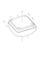
- FIG. 2 is a perspective view of the camera module according to the present embodiment.
- FIG. 3 is a schematic diagram of a moving body on which an imaging apparatus including the camera module shown in FIG. 1 is mounted.
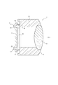
- 4 is a cross-sectional view taken along line AA in the camera module shown in FIG.
- FIG. 5 is a sectional view taken along line BB in the camera module shown in FIG.
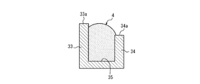
- FIG. 6A is a diagram illustrating a state in which the fixing member is filled in the groove.
- FIG. 6B is a diagram illustrating a state in which the imaging member is applied so as to be stacked on the end of the groove and the wall.
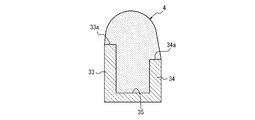
- FIG. 6C is a diagram illustrating a state in which the holding member is aligned from the state illustrated in FIG. 6B.
- FIG. 7 is an enlarged cross-sectional view of a portion joined to the holding member in the lens unit according to the first modification.
- FIG. 8 is an enlarged cross-sectional view of a portion joined to the holding member in the lens unit according to the second modification.
- FIG. 9A is an enlarged cross-sectional view of a portion of the lens unit that is joined to the holding member.
- FIG. 9B is a view of FIG. 9A viewed from the outer wall side.
- FIG. 10 is a perspective view of a lens unit according to Modification 4.
- the camera module 1 includes a holding member 2, a lens unit 3, and a fixing member 4 formed by curing an adhesive or the like.
- the lens unit 3 has a lens 31.
- the lens 31 is fixed to the lens unit 3.
- the holding member 2 and the lens unit 3 are fixed to each other as shown in FIG.
- the camera module 1 is included in an imaging device 5 as shown in FIG.
- the imaging device 5 is mounted on the moving body 6.
- the imaging device 5 mounted on the moving body 6 images, for example, the front side of the moving body 6.
- the imaging direction of the imaging device 5 is not limited to the front of the moving body 6.
- the imaging device 5 may image the side or rear of the moving body 6 or may image the inside of the moving body 6.
- the fixing member 4 is a resin such as epoxy, but is not limited thereto.
- the fixing member 4 is a cured resin such as a photo-curing resin that is cured by irradiating light (for example, UV (Ultra Violet) light) or a thermosetting resin that is cured by applying heat, but is not limited thereto.
- the fixing member 4 may be a UV and thermosetting fixing member that is cured by UV light irradiation and heating.
- the holding member 2 is a member that fixes and holds the image sensor 21 and the circuit element 22 such as a resistor, a capacitor, and a transistor.
- the image sensor 21 captures an image formed by the light incident on the internal space of the lens unit 3.
- the imaging element 21 is fixed at a position on the holding member 2 where light passing through the lens 31 of the lens unit 3 is imaged.
- the position at which light is imaged on the holding member 2 is on the inner side than the position where the light is joined to the lens unit 3, specifically, on the inner side of the holding member 2 where the fixing member 4 is disposed.
- the circuit element 22 is fixed to a position inside the holding member 2 where the image pickup element 21 is not disposed, on the inner side of the joining position with the lens unit 3.
- the holding member 2 is provided with one or more filling holes 23.
- the filling hole 23 is provided so as to face a part of a groove 35 described later in a state where the holding member 2 is fixed to the lens unit 3.
- the number of filling holes 23 is not limited to four.
- the lens unit 3 includes a lens 31 that allows light to enter the internal space, and a lens barrel portion 32 that opens along the optical axis OX of the lens 31.
- the lens barrel portion 32 is formed with an inner wall 33 that is a first wall portion and an outer wall 34 that is a second wall portion. Further, a groove 35 is formed in the lens barrel 32 by a surface of the inner wall 33 on the outer wall 34 side, a surface of the outer wall 34 on the inner wall 33 side, and a surface connecting the two surfaces.
- the lens 31 condenses the incident light so that the imaging element 21 forms an image.
- the lens 31 may be composed of, for example, a fisheye lens or an ultra wide angle lens.
- the lens 31 may be composed of a single lens or a plurality of lenses.
- the opening of the lens barrel portion 32 is a portion through which light incident on the lens 31 from the outside passes to reach the image sensor 21.
- One or more other lenses constituting an optical system together with the lens 31 or an optical material such as various filters can be disposed in the aperture.
- the inner wall 33 is disposed outside the opening in the lens unit 3 and is provided so as to protrude to the side facing the holding member 2. That is, the inner wall 33 can have a surface parallel to the optical axis OX direction. The direction of the surface of the inner wall 33 is not limited to this, and may be inclined to the optical axis OX.
- the outer side wall 34 is disposed on the side opposite to the optical axis OX with respect to the inner side wall 33, and is provided so as to protrude to the side facing the holding member 2. That is, the outer wall 34 can have a surface parallel to the optical axis OX direction. The direction of the surface of the outer side wall 34 is not limited to this, and may be inclined to the optical axis OX.
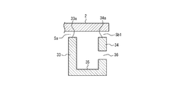
- the inner wall 33 and the outer wall 34 are opened so that the region sandwiched between the holding member 2 and the groove 35 is wider outside the lens unit 3 (outer space) than the inner space side including the optical axis OX of the lens 31. Is provided.
- the gap Sb between the outer wall 34 and the holding member 2 is larger than the gap Sa between the outer wall 34 and the holding member 2.
- the length of the outer wall 34 in the direction along the optical axis OX is shorter than the length of the inner wall 33 in the direction along the optical axis OX.
- the groove 35 accommodates the fixing member 4 at least partially.
- the opening of the groove 35 is directed to the holding member 2.
- the groove part 35 may be arrange
- the fixing member 4 is an adhesive or the like that fixes the lens unit 3 and the holding member 2.
- the fixing member 4 before curing is filled in the groove portion 35 and applied so as to be stacked on the end portions 33a and 34a of the inner side wall 33 and the outer side wall 34, respectively. .
- the fixing member 4 before curing is filled in the filling hole 23 and the side of the holding member 2 facing the lens unit 3 is further filled. It is applied so that it fills the periphery of the filling hole 23 on the opposite side.
- the fixing member 4 is exposed to the outside of the lens unit 3 more than the inner space surrounded by the lens unit 3 and the holding member 2.
- the “aligned state” between the lens 31 and the image pickup device 21 means that the optical axis OX direction of the lens 31, the direction orthogonal to the optical axis OX, and the rotation direction around the direction orthogonal to the optical axis OX direction, respectively. Is a state in which the alignment is performed.
- the fixing member 4 When the uncured fixing member 4 that has been filled and applied in this manner is cured, the fixing member 4 is accommodated in the groove 35 as shown in FIG. 4, and ends of the inner wall 33 and the outer wall 34 respectively. It joins with the lens unit 3 and the holding member 2 in the state arrange
- “fitting” means that two or more members are integrated by fitting to each other and their movements are restricted. Therefore, the holding member 2 and the lens unit 3 are fixed to each other via the fixing member 4.
- the fixing member 4 when the fixing member 4 is arranged so that the groove portion 35 surrounds the outside of the imaging element 21 over the entire periphery as described above, the fixing member 4 extends between the lens unit 3 and the holding member 2 along the entire periphery. Seal over.
- the fixing member 4 before curing is filled in the groove portion 35.
- the unfixed fixing member 4 is applied to the end portions 33 a and 34 a of the inner wall 33 and the outer wall 34, respectively.
- the lens 31 and the image sensor 21 are aligned so that they are aligned, and the holding member 2 is aligned with the lens unit 3 as shown in FIG. 6C.
- the fixing member 4 before curing is between the lens unit 3 and the holding member 2. Even if it sticks out, problems due to the protruding fixing member 4 can be reduced. Specifically, most of the fixing member 4 protrudes outside the groove portion 35 not through the gap Sa but through the gap Sb larger than the gap Sa. For this reason, there are few fixing members 4 which protrude inside the groove part 35, and it can reduce that the fixing member 4 adheres to the image pick-up element 21 or the circuit element 22 currently hold
- the inner wall 33, the outer wall 34, and the groove 35 are arranged so as to form a closed curve over the entire outer periphery of the opening, that is, when viewed from the optical axis OX direction. .
- the fixing member 4 is disposed inside the groove portion 35 and between the end portions 33 a and 34 a of the inner wall 33 and the outer wall 34 and the holding member 2. For this reason, it is possible to reduce dust, dust, and the like from entering the internal space from the outside of the lens unit 3. Therefore, it is possible to reduce the adhesion of dust and dirt to the image sensor 21, the circuit element 22, the lens 31, and the like, and it is possible to reduce problems that occur in the camera module 1.
- the lens unit 3 and the holding member 2 move in the direction of the optical axis OX by joining and fitting with the fixing member 4, respectively, and around the direction orthogonal to the optical axis OX. Is prevented from moving in the direction of rotation. Therefore, the distance between the lens 31 and the image sensor 21 is maintained, and a state in which the lens 31 is aligned with the direction of the optical axis OX and the rotational direction around the direction orthogonal to the optical axis OX is maintained. In addition, the movement in the direction orthogonal to the optical axis OX direction and the movement in the rotation direction around the optical axis OX direction are prevented. Therefore, the state aligned with the direction orthogonal to the optical axis OX direction and the rotation direction around the optical axis OX direction is maintained.
- the lens unit 3 and the holding member 2 are fixed by photocuring and / or heat-curing the fixing member 4 after alignment, so that it is possible to prevent positional displacement due to external force.
- the length of the outer wall 34 in the direction along the optical axis OX is shorter than the length of the inner wall 33 in the direction along the optical axis OX.
- the outer wall 34 may have a through hole 36 that penetrates the outer space.
- the size, shape, and number of the through holes 36 are arbitrary.
- the through hole 36 and the gap Sb ⁇ b> 1 between the outer wall 34 and the holding member 2 are portions that open to the external space side in the region sandwiched between the holding member 2 and the groove 35. .
- the number of fixing members 4 that protrude into the internal space of the groove 35 is less than the fixing members 4 that protrude into the external space. Therefore, it is possible to reduce the sticking of the protruding fixing member 4 to the image sensor 21 or the circuit element 22 held by the holding member 2.
- the end portion 34a of the outer wall 34 is described as a surface substantially perpendicular to the optical axis OX in FIGS. 6A, 6B, and 6C, but this is not restrictive.
- the end 34a may have a tapered shape that is inclined so as to be separated from the holding member 2 as it is separated from the optical axis OX.
- the fixing member 4 protrudes along the tapered surface when the holding member 2 is aligned with the lens unit 3
- the fixing member 4 protrudes along the tapered surface. Extruded.
- the amount of the fixing member 4 pushed through the gap Sa and into the internal space of the lens unit 3 is further reduced. Therefore, the fixing member 4 that protrudes inside the groove portion 35 is small, and adhesion to the imaging element 21, the circuit element 22, and the like can be further reduced.
- the length of the outer wall 34 in the direction along the optical axis OX is shorter than the length of the inner wall 33 in the direction along the optical axis OX.
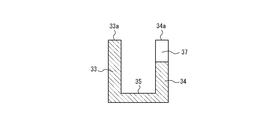
- the length of the outer wall 34 in the direction along the optical axis OX may be substantially the same as the length of the inner wall 33 in the direction along the optical axis OX.
- the outer wall 34 may have a notch 37.
- the length in the direction along the optical axis OX of at least a part of the outer wall 34 may be shorter than the length in the direction along the optical axis OX of the inner wall 33.
- the groove portion 35 is disposed over the entire outer periphery of the opening, but this is not restrictive.
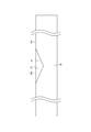
- the inner side wall 33, the outer side wall 34, and the groove part 35 may be provided in at least one part of the outer side of opening, as shown in FIG. In this case, since the material for forming the inner wall 33 and the outer wall 34 can be reduced, the cost can be reduced and the weight of the camera module 1 can be reduced.
- the holding member 2 is provided with one or more filling holes 23, but this is not a limitation. That is, the holding member 2 may not be provided with the filling hole 23.
- the fixing member 4 is accommodated in the groove portion 35 and joined to the lens unit 3 and the holding member 2 in a state where the fixing member 4 is disposed at the end portions 33a and 34a of the inner side wall 33 and the outer side wall 34, respectively. 3 and the holding member 2 are fixed.
- the fixing member 4 is not fitted to the holding member 2, but it is not necessary to apply the fixing member 4 before curing to the inside and the periphery of the filling hole 23, so that the assembly process of the camera module 1 is simplified. It becomes possible.
Landscapes
- Physics & Mathematics (AREA)
- General Physics & Mathematics (AREA)
- Engineering & Computer Science (AREA)
- Multimedia (AREA)
- Signal Processing (AREA)
- Optics & Photonics (AREA)
- Studio Devices (AREA)
- Lens Barrels (AREA)
- Camera Bodies And Camera Details Or Accessories (AREA)
Abstract
Selon l'invention, un module de caméra (1) est pourvu d'une unité objectif (3), d'un élément de retenue (2), et d'un élément de fixation (4). L'unité objectif (3) comporte une lentille (31) permettant de faire entrer la lumière dans un espace interne. L'élément de retenue (2) retient un élément d'imagerie (21) permettant de capturer une image formée par la lumière. L'élément de fixation (4) fixe l'unité objectif (3) et l'élément de retenue (2). L'élément de fixation (4) est une résine durcie. L'unité objectif (3) accueille au moins partiellement l'élément de fixation (4), et comporte une partie rainure (35), une ouverture de la partie rainure (35) étant orientée vers l'élément de retenue (2). Dans un état dans lequel l'unité objectif (3) et l'élément de retenue (2) sont fixés, davantage de l'élément de fixation (4) est exposé à l'extérieur de l'unité objectif par rapport à l'espace interne entouré par l'unité objectif (3) et l'élément de retenue (2).
Priority Applications (4)
| Application Number | Priority Date | Filing Date | Title |
|---|---|---|---|
| EP17846180.2A EP3505984B1 (fr) | 2016-08-29 | 2017-08-21 | Module de caméra, dispositif d'imagerie et corps mobile |
| CN201780052925.2A CN109643004B (zh) | 2016-08-29 | 2017-08-21 | 相机模块、摄像装置及移动体 |
| JP2018537134A JP6748721B2 (ja) | 2016-08-29 | 2017-08-21 | カメラモジュール、撮像装置、及び移動体 |
| US16/329,337 US10715710B2 (en) | 2016-08-29 | 2017-08-21 | Camera module, imaging apparatus, and vehicle |
Applications Claiming Priority (2)
| Application Number | Priority Date | Filing Date | Title |
|---|---|---|---|
| JP2016-167418 | 2016-08-29 | ||
| JP2016167418 | 2016-08-29 |
Publications (1)
| Publication Number | Publication Date |
|---|---|
| WO2018043172A1 true WO2018043172A1 (fr) | 2018-03-08 |
Family
ID=61301630
Family Applications (1)
| Application Number | Title | Priority Date | Filing Date |
|---|---|---|---|
| PCT/JP2017/029745 Ceased WO2018043172A1 (fr) | 2016-08-29 | 2017-08-21 | Module de caméra, dispositif d'imagerie et corps mobile |
Country Status (5)
| Country | Link |
|---|---|
| US (1) | US10715710B2 (fr) |
| EP (1) | EP3505984B1 (fr) |
| JP (1) | JP6748721B2 (fr) |
| CN (1) | CN109643004B (fr) |
| WO (1) | WO2018043172A1 (fr) |
Cited By (2)
| Publication number | Priority date | Publication date | Assignee | Title |
|---|---|---|---|---|
| WO2020245477A1 (fr) * | 2019-06-06 | 2020-12-10 | Universidad Pablo De Olavide | Système pour la neurostimulation |
| KR20220158822A (ko) * | 2020-03-30 | 2022-12-01 | 코너트 일렉트로닉스 리미티드 | 차량용 카메라를 장착하기 위한 방법, 카메라를 위한 사전-장착 모듈 및 카메라 |
Families Citing this family (4)
| Publication number | Priority date | Publication date | Assignee | Title |
|---|---|---|---|---|
| EP4236338B1 (fr) | 2017-05-22 | 2025-12-31 | Lg Innotek Co., Ltd. | Dispositif d'entraînement de lentille, module de caméra et dispositif optique |
| DE102018121367A1 (de) * | 2018-08-31 | 2020-03-05 | Carl Zeiss Ag | Optisches System zur Verwendung in einer Unterwasserumgebung |
| CN210007739U (zh) * | 2019-06-28 | 2020-01-31 | 三赢科技(深圳)有限公司 | 镜头模组及电子装置 |
| CN113438394A (zh) * | 2021-06-16 | 2021-09-24 | 蔚来汽车科技(安徽)有限公司 | 车载摄像头的前盖、车载摄像头装置和车辆 |
Citations (7)
| Publication number | Priority date | Publication date | Assignee | Title |
|---|---|---|---|---|
| JP2003289457A (ja) * | 2002-01-22 | 2003-10-10 | Casio Comput Co Ltd | 撮像装置 |
| JP2006086672A (ja) * | 2004-09-15 | 2006-03-30 | Nidec Copal Corp | 撮像モジュール |
| JP2007110594A (ja) * | 2005-10-17 | 2007-04-26 | Hitachi Maxell Ltd | カメラモジュール |
| JP2008028838A (ja) | 2006-07-24 | 2008-02-07 | Sharp Corp | カメラモジュールおよびその製造方法 |
| US20080297645A1 (en) * | 2007-05-30 | 2008-12-04 | Hon Hai Precision Industry Co., Ltd. | Camera module with compact packaging of image sensor chip and method of manufacturing the same |
| JP2012533775A (ja) * | 2009-12-21 | 2012-12-27 | フラウンホッファー−ゲゼルシャフト ツァ フェルダールング デァ アンゲヴァンテン フォアシュンク エー.ファオ | 光学積層体およびその製造方法 |
| JP2014093632A (ja) * | 2012-11-02 | 2014-05-19 | Konica Minolta Inc | カメラモジュールの製造方法、カメラモジュール及び携帯端末 |
Family Cites Families (8)
| Publication number | Priority date | Publication date | Assignee | Title |
|---|---|---|---|---|
| JP2000147345A (ja) * | 1998-11-16 | 2000-05-26 | Sony Corp | 光軸補正装置ならびに光軸補正装置製造装置および光軸補正装置製造方法 |
| JP2005236754A (ja) * | 2004-02-20 | 2005-09-02 | Toko Inc | イメージセンサモジュール |
| KR101316408B1 (ko) * | 2006-08-29 | 2013-10-08 | 엘지이노텍 주식회사 | 감시 장치 및 그 방법 |
| KR100832072B1 (ko) * | 2006-10-27 | 2008-05-27 | 삼성전기주식회사 | 카메라 모듈 |
| US20090079863A1 (en) * | 2007-09-20 | 2009-03-26 | Susumu Aoki | Camera module, manufacturing method of imaging apparatus and hot melt molding method |
| JP2012002979A (ja) * | 2010-06-16 | 2012-01-05 | Panasonic Corp | レンズ鏡筒、撮像装置および携帯端末装置 |
| TW201445857A (zh) * | 2013-05-30 | 2014-12-01 | Hon Hai Prec Ind Co Ltd | 音圈馬達及鏡頭模組 |
| CN104749858A (zh) * | 2015-03-12 | 2015-07-01 | 南昌欧菲光电技术有限公司 | 摄像头模组的支架及摄像头模组 |
-
2017
- 2017-08-21 JP JP2018537134A patent/JP6748721B2/ja active Active
- 2017-08-21 CN CN201780052925.2A patent/CN109643004B/zh active Active
- 2017-08-21 WO PCT/JP2017/029745 patent/WO2018043172A1/fr not_active Ceased
- 2017-08-21 EP EP17846180.2A patent/EP3505984B1/fr active Active
- 2017-08-21 US US16/329,337 patent/US10715710B2/en active Active
Patent Citations (7)
| Publication number | Priority date | Publication date | Assignee | Title |
|---|---|---|---|---|
| JP2003289457A (ja) * | 2002-01-22 | 2003-10-10 | Casio Comput Co Ltd | 撮像装置 |
| JP2006086672A (ja) * | 2004-09-15 | 2006-03-30 | Nidec Copal Corp | 撮像モジュール |
| JP2007110594A (ja) * | 2005-10-17 | 2007-04-26 | Hitachi Maxell Ltd | カメラモジュール |
| JP2008028838A (ja) | 2006-07-24 | 2008-02-07 | Sharp Corp | カメラモジュールおよびその製造方法 |
| US20080297645A1 (en) * | 2007-05-30 | 2008-12-04 | Hon Hai Precision Industry Co., Ltd. | Camera module with compact packaging of image sensor chip and method of manufacturing the same |
| JP2012533775A (ja) * | 2009-12-21 | 2012-12-27 | フラウンホッファー−ゲゼルシャフト ツァ フェルダールング デァ アンゲヴァンテン フォアシュンク エー.ファオ | 光学積層体およびその製造方法 |
| JP2014093632A (ja) * | 2012-11-02 | 2014-05-19 | Konica Minolta Inc | カメラモジュールの製造方法、カメラモジュール及び携帯端末 |
Non-Patent Citations (1)
| Title |
|---|
| See also references of EP3505984A4 |
Cited By (4)
| Publication number | Priority date | Publication date | Assignee | Title |
|---|---|---|---|---|
| WO2020245477A1 (fr) * | 2019-06-06 | 2020-12-10 | Universidad Pablo De Olavide | Système pour la neurostimulation |
| KR20220158822A (ko) * | 2020-03-30 | 2022-12-01 | 코너트 일렉트로닉스 리미티드 | 차량용 카메라를 장착하기 위한 방법, 카메라를 위한 사전-장착 모듈 및 카메라 |
| KR102753672B1 (ko) * | 2020-03-30 | 2025-01-14 | 코너트 일렉트로닉스 리미티드 | 차량용 카메라를 장착하기 위한 방법, 카메라를 위한 사전-장착 모듈 및 카메라 |
| US12233785B2 (en) | 2020-03-30 | 2025-02-25 | Connaught Electronics Ltd. | Method for mounting a camera for a vehicle, pre-mounting module for a camera as well as camera |
Also Published As
| Publication number | Publication date |
|---|---|
| EP3505984B1 (fr) | 2022-04-27 |
| US10715710B2 (en) | 2020-07-14 |
| JP6748721B2 (ja) | 2020-09-02 |
| EP3505984A4 (fr) | 2020-05-27 |
| EP3505984A1 (fr) | 2019-07-03 |
| CN109643004B (zh) | 2021-07-20 |
| JPWO2018043172A1 (ja) | 2019-06-24 |
| US20190222729A1 (en) | 2019-07-18 |
| CN109643004A (zh) | 2019-04-16 |
Similar Documents
| Publication | Publication Date | Title |
|---|---|---|
| JP6748721B2 (ja) | カメラモジュール、撮像装置、及び移動体 | |
| JP6578279B2 (ja) | 撮像装置、光学機器、電子機器、車両および撮像装置の製造方法 | |
| JP5601000B2 (ja) | 撮像装置 | |
| JP6626845B2 (ja) | 撮像装置、これを備える光学機器及び電子機器並びに撮像装置の製造方法 | |
| TWI620967B (zh) | 攝影模組 | |
| JP7205486B2 (ja) | 撮像装置 | |
| CN105376466B (zh) | 照相机模块 | |
| JP2011158793A5 (fr) | ||
| US10562467B2 (en) | Bonding structure, imaging apparatus, and on-vehicle camera | |
| JP6967424B2 (ja) | 撮像装置 | |
| JPWO2007010813A1 (ja) | レンズ鏡筒及びそのレンズ鏡筒を備えた撮像装置 | |
| JP6862146B2 (ja) | 光学機器 | |
| TWI633380B (zh) | 光學鏡片組、成像鏡頭與電子裝置 | |
| CN109076153B (zh) | 摄像组件和摄像装置 | |
| KR102118027B1 (ko) | 카메라 모듈 | |
| CN208076805U (zh) | 摄像装置 | |
| CN110892707B (zh) | 拍摄装置 | |
| JP2016020951A (ja) | レンズ鏡筒および光学機器 | |
| JP7163121B2 (ja) | 撮像装置 | |
| TWM545257U (zh) | 光學鏡片組、成像鏡頭與電子裝置 | |
| KR20170130836A (ko) | 카메라 모듈 | |
| JP6444613B2 (ja) | レンズ鏡筒及び撮像装置 | |
| JP2021047348A (ja) | 撮像装置 | |
| JP4765442B2 (ja) | 鏡胴ユニットおよび撮像装置 | |
| US9876947B2 (en) | Optical apparatus and image capturing apparatus |
Legal Events
| Date | Code | Title | Description |
|---|---|---|---|
| 121 | Ep: the epo has been informed by wipo that ep was designated in this application |
Ref document number: 17846180 Country of ref document: EP Kind code of ref document: A1 |
|
| ENP | Entry into the national phase |
Ref document number: 2018537134 Country of ref document: JP Kind code of ref document: A |
|
| NENP | Non-entry into the national phase |
Ref country code: DE |
|
| WWE | Wipo information: entry into national phase |
Ref document number: 2017846180 Country of ref document: EP |