WO2018043207A1 - Dispositif de communication sans fil - Google Patents
Dispositif de communication sans fil Download PDFInfo
- Publication number
- WO2018043207A1 WO2018043207A1 PCT/JP2017/029929 JP2017029929W WO2018043207A1 WO 2018043207 A1 WO2018043207 A1 WO 2018043207A1 JP 2017029929 W JP2017029929 W JP 2017029929W WO 2018043207 A1 WO2018043207 A1 WO 2018043207A1
- Authority
- WO
- WIPO (PCT)
- Prior art keywords
- wireless communication
- antenna
- substrate
- circuit
- registered trademark
- Prior art date
- Legal status (The legal status is an assumption and is not a legal conclusion. Google has not performed a legal analysis and makes no representation as to the accuracy of the status listed.)
- Ceased
Links
Images




Classifications
-
- H—ELECTRICITY
- H04—ELECTRIC COMMUNICATION TECHNIQUE
- H04B—TRANSMISSION
- H04B1/00—Details of transmission systems, not covered by a single one of groups H04B3/00 - H04B13/00; Details of transmission systems not characterised by the medium used for transmission
- H04B1/38—Transceivers, i.e. devices in which transmitter and receiver form a structural unit and in which at least one part is used for functions of transmitting and receiving
- H04B1/40—Circuits
- H04B1/50—Circuits using different frequencies for the two directions of communication
- H04B1/52—Hybrid arrangements, i.e. arrangements for transition from single-path two-direction transmission to single-direction transmission on each of two paths or vice versa
- H04B1/525—Hybrid arrangements, i.e. arrangements for transition from single-path two-direction transmission to single-direction transmission on each of two paths or vice versa with means for reducing leakage of transmitter signal into the receiver
-
- H—ELECTRICITY
- H04—ELECTRIC COMMUNICATION TECHNIQUE
- H04W—WIRELESS COMMUNICATION NETWORKS
- H04W72/00—Local resource management
- H04W72/04—Wireless resource allocation
- H04W72/044—Wireless resource allocation based on the type of the allocated resource
- H04W72/0453—Resources in frequency domain, e.g. a carrier in FDMA
-
- H—ELECTRICITY
- H01—ELECTRIC ELEMENTS
- H01Q—ANTENNAS, i.e. RADIO AERIALS
- H01Q1/00—Details of, or arrangements associated with, antennas
- H01Q1/12—Supports; Mounting means
- H01Q1/22—Supports; Mounting means by structural association with other equipment or articles
- H01Q1/24—Supports; Mounting means by structural association with other equipment or articles with receiving set
-
- H—ELECTRICITY
- H01—ELECTRIC ELEMENTS
- H01Q—ANTENNAS, i.e. RADIO AERIALS
- H01Q1/00—Details of, or arrangements associated with, antennas
- H01Q1/52—Means for reducing coupling between antennas; Means for reducing coupling between an antenna and another structure
-
- H—ELECTRICITY
- H04—ELECTRIC COMMUNICATION TECHNIQUE
- H04B—TRANSMISSION
- H04B1/00—Details of transmission systems, not covered by a single one of groups H04B3/00 - H04B13/00; Details of transmission systems not characterised by the medium used for transmission
-
- H—ELECTRICITY
- H04—ELECTRIC COMMUNICATION TECHNIQUE
- H04B—TRANSMISSION
- H04B1/00—Details of transmission systems, not covered by a single one of groups H04B3/00 - H04B13/00; Details of transmission systems not characterised by the medium used for transmission
- H04B1/38—Transceivers, i.e. devices in which transmitter and receiver form a structural unit and in which at least one part is used for functions of transmitting and receiving
- H04B1/40—Circuits
-
- H—ELECTRICITY
- H04—ELECTRIC COMMUNICATION TECHNIQUE
- H04B—TRANSMISSION
- H04B1/00—Details of transmission systems, not covered by a single one of groups H04B3/00 - H04B13/00; Details of transmission systems not characterised by the medium used for transmission
- H04B1/38—Transceivers, i.e. devices in which transmitter and receiver form a structural unit and in which at least one part is used for functions of transmitting and receiving
- H04B1/40—Circuits
- H04B1/403—Circuits using the same oscillator for generating both the transmitter frequency and the receiver local oscillator frequency
- H04B1/406—Circuits using the same oscillator for generating both the transmitter frequency and the receiver local oscillator frequency with more than one transmission mode, e.g. analog and digital modes
Definitions
- the present invention relates to a wireless communication device, and more particularly, to a wireless communication device that performs wireless communication using a plurality of different wireless communication methods using the same frequency band.
- Non-Patent Document 1 a wireless communication device that performs wireless communication using a plurality of wireless communication methods has been proposed (for example, see Non-Patent Document 1).
- Non-Patent Document 1 discloses a gateway that supports two types of wireless communication systems, wireless LAN (Wi-Fi (registered trademark)) and Bluetooth (registered trademark). According to this gateway, it is possible to connect to any gateway that is a device compatible with a wireless LAN or a device compatible with Bluetooth (registered trademark).
- Wi-Fi registered trademark
- Bluetooth registered trademark
- Non-Patent Document 1 wireless communication by a plurality of different wireless communication methods using the same frequency band cannot be used together (simultaneously used) or smooth when used together. There is a problem that proper communication is not performed. That is, in the gateway disclosed in Non-Patent Document 1, smooth communication is not performed when wireless communication using Wi-Fi (registered trademark) and Bluetooth (registered trademark) is used in the same frequency band. Due to radio wave interference, in-channel interference that causes reception errors when signals from other stations enter the receiving band directly, out-of-band noise of signals from other stations, distortion due to reception of signals from other stations, etc. This is because inter-channel interference that causes a reception error occurs, or by detecting signals from other stations, carrier sense that suppresses transmission of the own station (loses a transmission opportunity) frequently occurs.
- Wi-Fi registered trademark
- Bluetooth registered trademark
- 2.4 GHz band is used in wireless communication systems such as Wi-Fi (registered trademark), Bluetooth (registered trademark), and ZigBee (registered trademark).
- Wi-Fi registered trademark
- Bluetooth registered trademark
- ZigBee registered trademark
- a wireless communication device capable of performing wireless communication is desired.
- Wi-SUN registered trademark
- EnOcean registered trademark
- LoRa registered trademark
- Sigfox registered trademark
- Wi-SUN registered trademark
- EnOcean registered trademark
- LoRa registered trademark
- Sigfox registered trademark
- a conventional wireless communication device cannot use wireless communication by a plurality of different wireless communication methods using the same frequency band, or performs wireless communication by such a plurality of wireless communication methods simultaneously and smoothly.
- the lighting fixtures are controlled by wireless communication using ZigBee (registered trademark) in parallel with receiving operation commands from a smartphone via a Wi-Fi (registered trademark) wireless LAN.
- ZigBee registered trademark
- Wi-Fi registered trademark
- an object of the present invention is to provide a wireless communication apparatus that can simultaneously and smoothly perform wireless communication by a plurality of different wireless communication systems using the same frequency band.
- a wireless communication apparatus includes a housing and a first substrate housed in the housing, and the first substrate has a first frequency band.
- a first communication circuit and a first antenna that perform wireless communication using the first wireless communication method to be used, and a second wireless communication method that uses the first frequency band and performs a second wireless communication method different from the first wireless communication method.
- a communication circuit and a second antenna are mounted, and the first antenna and the second antenna are respectively disposed in a first area and a second area that are diagonally positioned in a plan view of the first substrate. Yes.
- the first antenna and the second antenna corresponding to a plurality of different wireless communication systems using the same frequency band are respectively in a first area and a second area having a diagonal positional relationship in plan view of the first substrate.
- radio wave interference is suppressed, the frequency of retransmission in wireless communication caused by the interference is also suppressed, and power consumption associated with retransmission is reduced.
- the first antenna and the second antenna may be arranged on the first substrate such that main radiation directions are orthogonal to each other.
- the first substrate further includes a third communication circuit and a third antenna for performing wireless communication by a third wireless communication method using a second frequency band different from the first frequency band, and the second frequency band.
- a fourth communication circuit and a fourth antenna for performing wireless communication in a fourth wireless communication method different from the third wireless communication method, and the third antenna and the fourth antenna are respectively It may be arranged in a third region and a fourth region that are different from both the first region and the second region and have a diagonal positional relationship in plan view of the first substrate.
- the third antenna and the fourth antenna corresponding to different wireless communication schemes using the second frequency band different from the first frequency band are also respectively similar to the relationship with the first antenna and the second antenna. Since they are arranged in the third region and the fourth region that are diagonally positioned in plan view of one substrate and are separated from each other, wireless communication using the third antenna and wireless using the fourth antenna Interference of radio waves in communication is suppressed. Therefore, two sets of different two types of wireless communication systems using the same frequency band, that is, wireless communication using the four types of wireless communication systems can be performed simultaneously and smoothly.
- the third antenna and the fourth antenna may be arranged on the first substrate so that main radiation directions are orthogonal to each other.
- the main radiation direction of the third antenna and the main radiation direction of the fourth antenna that use the same frequency band are also orthogonal to each other, like the first antenna and the second antenna, and therefore wireless communication using the third antenna.
- radio wave interference in radio communication using the fourth antenna is further suppressed, and a radio communication device with good reception sensitivity is realized.
- the first communication circuit and the first antenna use the widest frequency band among the communication circuit and antenna mounted on the first substrate, or the communication circuit mounted on the first substrate.
- the third communication circuit and the third antenna, the first communication circuit and the first antenna among the communication circuit and the antenna mounted on the first substrate may be disposed at a position closest to the antenna, and may be disposed on a first plane on which the first communication circuit and the first antenna are disposed, and a second plane having a different height from the first substrate.
- the first plane may be a main surface of the first substrate, and the second plane may be a main surface of a second substrate connected to the first substrate via a substrate connecting connector. .
- the first communication circuit and the first antenna, and the third communication circuit and the third antenna are arranged on different boards connected via the board connecting connector, and these boards are detachable.
- the combination of substrates used at the same time can be easily changed to flexibly meet various needs.
- the third wireless communication method may be a wireless communication method of a type in which at least one of a frequency band and a wireless communication method used depending on a destination of the wireless communication device is different.
- the second board on which the third communication circuit and the third antenna are arranged is connected to the first board via the board connecting connector, so that the second board matches the destination of the wireless communication device.
- the first substrate is further mounted with a power supply circuit, a logic circuit, and a shield case that houses at least one of the power supply circuit and the logic circuit, and the shield case is a plan view of the first substrate. And having an outline having an inner angle larger than 180 degrees, an opening is formed in a side surface corresponding to the inner angle of the shield case, and the first communication circuit, the first antenna, the second communication circuit, The second antenna may be arranged at a position on the first substrate such that none of the second antenna can be seen when viewed from the inside of the shield case through the opening.
- the first communication circuit, the first antenna, the second communication circuit, and the second antenna are affected by electromagnetic noise leaking from the opening. Since it is arranged at a position where it is difficult to receive, stable communication is ensured.
- the first antenna and the second antenna are disposed along a side of the first substrate in a plan view of the first substrate, and are further placed outside the casing on the first substrate.
- An external device connector for connecting an external device that performs wireless communication with a wireless communication method different from any of the first wireless communication method and the second wireless communication method, and the wireless communication device;
- the connector may be disposed along a side of the first substrate that is different from any of the side of the first substrate on which the first antenna is disposed and the side of the first substrate on which the second antenna is disposed. Good.
- the external device connector for connecting to an external device that performs wireless communication using a wireless communication method different from the wireless communication method employed by the wireless communication device can be used for either the first antenna or the second antenna. Since it is arranged at a position where it is difficult to interfere with each other, stable wireless communication by an external device added via an external device connector becomes possible.
- a wireless communication apparatus that can simultaneously and smoothly perform wireless communication using a plurality of different wireless communication systems using the same frequency band is realized.
- FIG. 1 is a diagram illustrating an application example of a wireless communication device in an embodiment.
- FIG. 2 is a mounting layout diagram showing the configuration of the wireless communication apparatus shown in FIG.
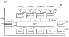
- FIG. 3 is a block diagram showing a connection relationship of various circuit elements shown in FIG.
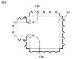
- FIG. 4 is a diagram illustrating an example of a development view of the shield case shown in FIG. 1.
- FIG. 5 is a mounting layout diagram illustrating a configuration of a wireless communication apparatus according to a modification of the embodiment.
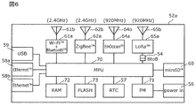
- FIG. 6 is a block diagram showing the connection relationship of the various circuit elements shown in FIG.
- FIG. 7 is a diagram illustrating a mounting example of the communication circuit and the antenna on the first substrate having an L-shape.
- FIG. 1 is a diagram illustrating an application example of the wireless communication device 50 according to the embodiment.
- a wireless LAN Wi-Fi (registered trademark)
- Bluetooth registered trademark
- ZigBee registered trademark
- Wi--- which is an example of the third wireless communication system, using the 920 MHz band as the second frequency band.
- the gateway By using a combination of SUN (registered trademark) and wireless communication of a total of four types of wireless communication methods, EnOcean (registered trademark), which is an example of a fourth wireless communication method using the same 920 MHz band as the second frequency band, the gateway And a wireless communication device 50 that functions as a device controller that controls various devices.
- SUN registered trademark
- EnOcean registered trademark
- the gateway By using a combination of SUN (registered trademark) and wireless communication of a total of four types of wireless communication methods, EnOcean (registered trademark), which is an example of a fourth wireless communication method using the same 920 MHz band as the second frequency band, the gateway And a wireless communication device 50 that functions as a device controller that controls various devices.
- the lighting fixtures 12a and 12b constitute a ZigBee (registered trademark) mesh network
- the wireless communication device 50 functions as a coordinator.
- battery-driven illuminance sensors 14 are arranged everywhere in the room, and these are also collected into the wireless communication device 50 through the ZigBee (registered trademark) mesh network.
- Lighting switches 22a and 22b using an energy harvesting power source by EnOcean are arranged in the room, and the wireless communication device 50 waits for transmission data from the lighting switches 22a and 22b.
- the smart meter 32a, the HEMS (Home Energy Management System) controller 32b, and the wireless communication device 50 are connected by Wi-SUN (registered trademark), and the wireless communication device 50 sequentially monitors the power usage status.
- Demand response information such as the tightness of the power supply status is transmitted via the B route or the like.
- the wireless communication device 50 Based on this demand response information, the wireless communication device 50 performs energy saving control such as turning off indoor lighting in a place where the human sensor is not responding.
- the smartphone 44 and the wireless communication device 50 are connected via Bluetooth (registered trademark), and the smartphone 44 can perform illumination control using an application for illumination control. Furthermore, it is possible to access the setting screen (Web control) of the wireless communication device 50 by Wi-Fi (registered trademark) from the personal computer (PC) 42 or the smartphone 44 to set the lighting control or check the usage status. .
- Wi-Fi registered trademark
- FIG. 2 is a diagram showing a configuration of the wireless communication device 50 shown in FIG. Here, a mounting layout of circuit boards (the first board 52 and the second board 55) housed in a casing 51 provided in the wireless communication device 50 is shown.
- the first substrate 52 performs first wireless communication using Wi-Fi (registered trademark) and Bluetooth (registered trademark) that can be selectively used using the 2.4 GHz band as four sets of communication circuits and antennas.
- a third communication circuit 63a and a third antenna 63b to be performed, and a fourth communication circuit 64a and a fourth antenna 64b to perform wireless communication by EnOcean (registered trademark) using the 920 MHz band are mounted.
- the first communication circuit 61a is a combo chip compatible with Wi-Fi (registered trademark) and Bluetooth (registered trademark) wireless communication systems using a single band of 2.4 GHz band.
- the third communication circuit 63a and the third antenna 63b are arranged on a second substrate 55 as a child substrate connected to a first substrate 52 as a parent substrate via a substrate connection connector (BtoB) 54. ing.
- the first antenna 61b, the second antenna 62b, the third antenna 63b, and the fourth antenna 64b are formed on the main surface (that is, the surface on which circuit components are mounted) of the first substrate 52 or the second substrate 55. It may be a wiring pattern, a conductor erected from the substrate, or a mixture thereof.
- substrate 52 has a rectangular outline in this Embodiment, as mentioned later, it is not limited to such an outline.
- an MPU (Micro-processing unit) 70, a RAM 72, a flash memory 73, an Ethernet (registered trademark) IC (Ether PHY) 74, and a real-time clock (RTC) 57 are mounted as logic circuits.
- a power management IC (PM) 71 is mounted as a power supply circuit.
- the MPU 70, the power management IC 71, the RAM 72, the flash memory 73, and the Ethernet (registered trademark) IC 74 are housed in a shield case 53 having a lid structure in order to suppress unnecessary electromagnetic noise radiation to peripheral communication circuits. Has been. Details of the shield case 53 will be described later.
- the first substrate 52 includes a power supply terminal 56, Ethernet (registered trademark) ports 58a and 58b, and microSD (registered trademark) as various connectors for connecting to a power supply or an external device. 60 is implemented.
- Ethernet registered trademark
- microSD registered trademark
- “mounted (or arranged) on the board” is not only directly mounted (or arranged) on the board, but also other components such as the board connecting connector 54. It is also included that it is indirectly mounted (or arranged) on the substrate via
- FIG. 3 is a block diagram showing a connection relationship between various circuit elements mounted on the first substrate 52 and the second substrate 55 shown in FIG.
- the microSD (registered trademark) 60 is connected to the MPU 70
- the third communication circuit 63 a is connected to the MPU 70 via the board connection connector 54.
- the power management IC 71 receives DC power supplied from the outside via the power supply terminal 56, generates various DC voltages required in the wireless communication device 50 at appropriate timing, and supplies them to various circuit elements. .
- the Ethernet (registered trademark) ports 58a and 58b are used as a WAN port and a LAN port constituting a home network in order to connect to the external Internet, or as a LAN HUB.
- the MPU 70 includes a ROM in which a control program is stored, a processor that executes the control program, and the like, and the processor executes the control program to exchange data and control signals with various circuit elements connected to the MPU 70.
- the wireless communication device 50 functions as the gateway and device controller shown in FIG.
- Characteristic points of the wireless communication device 50 in the present embodiment configured as described above are as follows.
- the first antenna 61b for Wi-Fi (registered trademark) and Bluetooth (registered trademark) using the 2.4 GHz band and the second antenna 62b for ZigBee (registered trademark) using the same 2.4 GHz band are the first The substrate 52 is disposed in a first region and a second region that are in a diagonal positional relationship in plan view.
- the first antenna 61 b is disposed in the upper right region (first region) of the first substrate 52, while the second antenna 62 b is disposed on the first substrate 52. It is arranged in the lower left area (second area).
- the first antenna 61b and the second antenna 62b corresponding to a plurality of different wireless communication systems using the same frequency band are arranged at positions separated from each other, and thus Wi-Fi using the first antenna 61b is used.
- Interference of radio waves in wireless communication based on (registered trademark) and Bluetooth (registered trademark) and wireless communication based on ZigBee (registered trademark) using the second antenna 62b is suppressed.
- Wi-Fi (registered trademark) and Bluetooth (registered trademark) and ZigBee (registered trademark)) using the same frequency band can be performed simultaneously and smoothly. It becomes.
- the size of the first substrate 52 can be made smaller than before, and the wireless communication device 50 can be miniaturized and highly integrated. Furthermore, since radio wave interference is suppressed, the frequency of retransmission in wireless communication caused by the interference is also suppressed, and power consumption associated with retransmission is reduced.
- the third antenna 63b and the fourth antenna 64b are different from both the first region and the second region. And it is arrange
- the third antenna 63b is disposed in the lower right region (third region) of the first substrate 52, while the fourth antenna 64b is disposed on the first substrate. 52 is arranged in the upper left area (fourth area).
- the third antenna 63b and the fourth antenna 64b corresponding to a plurality of different wireless communication systems using the same frequency band are also located at positions separated from each other, like the first antenna 61b and the second antenna 62b. Therefore, radio wave interference in Wi-SUN (registered trademark) wireless communication using the third antenna 63b and EnOcean (registered trademark) wireless communication using the fourth antenna 64b is suppressed. As a result, it is possible to simultaneously and smoothly perform wireless communication using a plurality of different wireless communication systems (Wi-SUN (registered trademark) and EnOcean (registered trademark)) using the same frequency band.
- Wi-SUN registered trademark
- EnOcean registered trademark
- the size of the first substrate 52 can be made smaller than before, and the wireless communication device 50 can be miniaturized and highly integrated. Furthermore, since radio wave interference is suppressed, the frequency of retransmission in wireless communication caused by the interference is also suppressed, and power consumption associated with retransmission is reduced.
- two regions in a diagonal position relationship are predetermined from two vertices of the first substrate 52 in a diagonal position relationship in plan view of the first substrate 52. It may be a region within a range (for example, a distance corresponding to 10% of the diagonal line), and among the antennas mounted on the first substrate 52, the antenna is arranged at a position closest to each of the two vertices. It may mean that the region may be a region along the side of the first substrate 52 connected to each of the two vertices.
- the first antenna 61b for Wi-Fi (registered trademark) and Bluetooth (registered trademark) using the 2.4 GHz band and the second antenna 62b for ZigBee (registered trademark) using the same 2.4 GHz band are: It arrange
- the first antenna 61b is arranged so as to extend along the right side of the first substrate 52 having a rectangular outline, while the second antenna 62b is The first substrate 52 is disposed so as to extend along the lower side.
- the main radiation directions of the first antenna 61b and the second antenna 62b are orthogonal to each other.
- the main radiation direction of the first antenna 61b using the same frequency band and the main radiation direction of the second antenna 62b are orthogonal to each other. Therefore, Wi-Fi (registered trademark) and Bluetooth (registered trademark) using the first antenna 61b are used. ) And radio wave interference in ZigBee (registered trademark) using the second antenna 62b is further suppressed, and the radio communication device 50 with good reception sensitivity is realized.
- the third antenna 63b and the fourth antenna 64b are arranged so that the main radiation directions are orthogonal to each other.
- the third antenna 63b for Wi-SUN (registered trademark) using the 920 MHz band and the fourth antenna 64b for EnOcean (registered trademark) using the same 920 MHz band are arranged so that the main radiation directions are orthogonal to each other.
- the third antenna 63 b is arranged to extend along the lower side of the first substrate 52 having a rectangular outline, while the fourth antenna 64 b is The first substrate 52 is disposed so as to extend along the left side.
- the main radiation directions of the third antenna 63b and the fourth antenna 64b are orthogonal to each other.
- the main radiation direction of the third antenna 63b and the main radiation direction of the fourth antenna 64b that use the same frequency band are also orthogonal to each other, like the first antenna 61b and the second antenna 62b.
- Interference of radio waves in wireless communication using Wi-SUN (registered trademark) using the wireless communication and wireless communication using EnOcean (registered trademark) using the fourth antenna 64b is further suppressed, and the wireless communication device 50 with high reception sensitivity is realized.
- perpendicular means substantially orthogonal to the extent that the effect of suppressing radio wave interference is exhibited. For example, a state of intersecting at an angle of 80 to 100 degrees is also possible. included.
- the widest frequency band is used among the communication circuits and antennas mounted on the first substrate 52, or communication is performed with the highest frequency among the communication circuits and antennas mounted on the first substrate 52.
- a communication circuit and an antenna (here, Wi-SUN (registered trademark) using a 920 MHz band) mounted at a position closest to the first communication circuit 61 a and the first antenna 61 b for performing wireless communication by Wi-Fi (registered trademark).
- the third communication circuit 63a and the third antenna 63b) for performing wireless communication include a first plane (here, the main surface of the first substrate 52) on which the first communication circuit 61a and the first antenna 61b are arranged, and the first.
- the third communication circuit 63a and the third antenna 63b that perform wireless communication by Wi-SUN (registered trademark) using the 920 MHz band are not mounted on the first board 52 but are connected to the first board 52 for board connection. It is mounted as a module with a built-in antenna (a module including the second substrate 55) connected via the connector 54.
- Wi-Fi (registered trademark) and Wi-SUN (registered trademark) use different frequency bands, but Wi-Fi (registered trademark) communicates in a wide band and communicates at a high frequency. There is a possibility of causing out-of-band interference to the first communication circuit 61a that performs wireless communication by Wi-Fi (registered trademark) on the first substrate 52 and the communication circuit and the antenna disposed near the first antenna 61b. .
- the first communication circuit 61a and the first antenna 61b, and the third communication circuit 63a and the third antenna 63b that are mounted closest to the first communication circuit 61a and the first antenna 61b are arranged in planes having different heights, compared with the case where they are arranged in the same plane, wireless communication using the first communication circuit 61a and the first antenna 61b (that is, Wi ⁇ using the 2.4 GHz band).
- Fi registered trademark
- wireless communication using Bluetooth registered trademark
- radio communication using the third communication circuit 63a and the third antenna 63b wireless communication using Wi-SUN (registered trademark) using the 920 MHz band. External interference is suppressed.
- the first communication circuit 61a and the first antenna 61b and the third communication circuit 63a and the third antenna 63b are arranged on different boards connected via the board connection connector 54, and these boards are attached and detached. Since it is possible, the combination of the board
- a shield case 53 that houses at least one of a power supply circuit and a logic circuit is mounted on the first substrate 52, and the shield case 53 has inner angles 53a and 53b larger than 180 degrees in a plan view of the first substrate 52. Openings 53c and 53d are formed on the side surfaces corresponding to the inner angles 53a and 53b of the shield case 53, respectively, and the first communication circuit 61a and the first antenna 61b, the second communication circuit 62a and the second When the antenna 62b, the third communication circuit 63a and the third antenna 63b, and the fourth communication circuit 64a and the fourth antenna 64b are viewed from the inside of the shield case 53 through the openings 53c and 53d, any It is arranged at the position of the first substrate 52 so that the surface cannot be seen.
- “invisible” when the shield case 53 is viewed from the outside means a positional relationship in which electromagnetic noise leaking from the openings 53c and 53d is not directly radiated to the communication circuit and the antenna. However, this includes a case where other circuit components exist between the openings 53c and 53d and the communication circuit and antenna.
- the shield case 53 is formed by inexpensive punching / bending processing from a single sheet of white or the like as shown in the development view shown in FIG. 4, and includes an MPU 70, a power management IC 71, and a RAM 72. Further, while covering logic circuits such as the flash memory 73 and the Ethernet (registered trademark) IC 74, they are nipped into the through holes formed in the first substrate 52 and fixed by soldering.
- the planar shape of the shield case 53 is a convex shape (that is, there are inner angles 53a and 53b larger than 180 degrees in the outline in plan view), a gap (partially between the side surfaces of the inner corners ( Openings 53c and 53d) occur (see FIG. 2).
- the openings 53c and 53d are directed to the power supply terminal 56 and the real-time clock 57 (open), and the openings 53c and 53d are connected to any of the four types of communication circuits and antennas. Direct leakage of leaking electromagnetic noise is suppressed.
- FIG. 5 is a diagram illustrating a configuration of a wireless communication device 50a according to a modification of the embodiment.
- the mounting layout of the circuit boards (the first board 52a and the second board 55a) housed in the casing 51 provided in the wireless communication device 50a is shown.
- FIG. 6 is a block diagram showing a connection relationship between various circuit elements mounted on the first substrate 52a and the second substrate 55a shown in FIG.
- a USB port 59 is mounted on the first board 52a, and Wi-SUN (registration) is provided on the second board 55a as the third wireless communication system in the above embodiment.
- Wi-SUN registration
- another third communication circuit 65a and a third antenna 65b corresponding to the LoRa (registered trademark) wireless communication system are mounted.
- the USB port 59 is placed outside the casing 51 and used by the wireless communication device 50a (first wireless communication method (Wi-Fi (registered trademark) and Bluetooth (registered trademark)), second wireless communication.
- An external device connected to the USB port 59 includes a 3G / LTE dongle. As a result, wireless communication by a newly added wireless communication method different from the wireless communication method employed by the wireless communication device 50a is possible.
- the USB port 59 is a side of the first substrate 52a on which the antenna included in the wireless communication device 50a is arranged (that is, the right side of the first substrate 52a on which the first antenna 61b is arranged). Any of the lower side of the first substrate 52a on which the second antenna 62b is arranged, the lower side of the first substrate 52a on which the third antenna 65b is arranged, and the left side of the first substrate 52a on which the fourth antenna 64b is arranged) They are arranged along the side (that is, the upper side) of the first substrate 52a different from the first substrate 52a.
- the USB port 59 for connecting to an external device for example, 3G / LTE dongle
- an external device for example, 3G / LTE dongle
- 4 is arranged at a position where it is difficult to interfere with any of the wireless communication using the four antennas included in the wireless communication device, so that stable wireless communication can be performed by an external device added via the USB port 59.
- the communication circuit and the antenna (external device) to be added are not limited to a USB dongle, but may be a unique connector, a card connected to SDIO (Secure Digital Input / Output), or the like.
- the second substrate 55a in the present modified example is different from the third wireless communication method using the 920 MHz band in order to correspond to the destination that adopts LoRa (registered trademark) as the wireless communication method in the smart grid.
- a third communication circuit 65a and a third antenna 65b that perform wireless communication using LoRa (registered trademark) as an example are mounted.
- the second substrate 55a on which the third communication circuit 65a and the third antenna 65b are disposed is connected to the first substrate 52a via the substrate connection connector 54.
- wireless communication by Sigfox which is another example of the third wireless communication method using the 800/900 MHz band as a communication circuit and an antenna mounted on the second substrate 55a.
- a communication circuit and an antenna for performing the above may be mounted.
- a plurality of different wireless communication schemes are adopted for each of two different frequency bands (2.4 GHz band and 800/900 MHz band), but the present invention is not limited to such a combination.
- a plurality of different wireless communication methods may be employed in at least one frequency band.
- only two different wireless communication systems using the 2.4 GHz band may be adopted, or two different wireless communication systems using the 2.4 GHz band and one wireless communication system using the 800/900 MHz band. It may be adopted.
- the frequency band used for wireless communication is not limited to the 2.4 GHz band and the 800/900 MHz band, and may be another frequency band such as a 5 GHz band.
- the first communication circuit 61a and the first antenna 61b may be compatible with Wi-Fi (registered trademark) using the 2.4 GHz band and the 5 GHz band and Bluetooth (registered trademark) using the 2.4 GHz band.
- substrates 52 and 52a was a rectangle, it is not limited to such a shape, Various types, such as circular, an ellipse, a hexagon, etc. It may be a polygon, an L-shape, a concave shape, a convex shape, a shape obtained by cutting out a part thereof, or various variants obtained by combining them.
- FIG. 7 is a diagram illustrating a mounting example of the communication circuit and the antenna on the first substrate 52b having an L-shape.
- first communication circuit 61a and first antenna 61b second communication circuit 62a and second antenna 62b, third communication circuit 63a and third communication circuit. Only the mounting positions of the antenna 63b, the fourth communication circuit 64a and the fourth antenna 64b) are shown.
- the first antenna 61b and the second antenna 62b are respectively disposed in the first region and the second region that are in a diagonal positional relationship in plan view of the first substrate 52b. This is because the first antenna 61b and the second antenna 62b are arranged in a region having a diagonal positional relationship in the circumscribed rectangular region 82 of the L-shaped first substrate 52b.
- the third antenna 63b and the fourth antenna 64b are also arranged in the third region and the fourth region, respectively, which are in a diagonal positional relationship in the plan view of the first substrate 52b.
- the third antenna 63b and the fourth antenna 64b are diagonal in one of the two rectangular regions 81a and 81b (rectangular region 81b) obtained by dividing the L-shaped first substrate 52b by the partition line 80. This is because they are arranged in a region having a positional relationship.
- the “region having the diagonal positional relationship in the plan view of the first substrate” includes not only the diagonal positional relationship in the case where the first substrate is a rectangular region, but also the first substrate.
- An area having a diagonal positional relationship in the circumscribed rectangular area and a region having a diagonal positional relationship in a rectangular area obtained by separating the first substrate into a plurality of rectangular areas are also included.
- the communication circuit and antenna mounted on the first substrate 52b use the widest frequency band, or the communication is mounted on the first substrate 52b.
- the first communication circuit 61a and the first antenna 61b that perform wireless communication by Wi-Fi (registered trademark) that performs communication at the highest frequency among the circuits and antennas are mounted with other three types of communication circuits and antennas. It is mounted in a rectangular area 81a different from the rectangular area 81b. As a result, in-band interference or out-of-band interference between the first communication circuit 61a and the first antenna 61b in which wireless communication is performed in a wide band or at a high frequency and the other three types of communication circuits and antennas is suppressed.
- the present invention is a wireless communication device, in particular, a device that performs wireless communication by a plurality of different wireless communication methods using the same frequency band, such as a lighting fixture, an illuminance sensor, a lighting switch, a smart meter, a smartphone, a PC, etc. It can be used as a gateway or device controller that controls devices by performing wireless communication with various devices.
Landscapes
- Engineering & Computer Science (AREA)
- Computer Networks & Wireless Communication (AREA)
- Signal Processing (AREA)
- Transceivers (AREA)
- Telephone Set Structure (AREA)
- Variable-Direction Aerials And Aerial Arrays (AREA)
- Support Of Aerials (AREA)
- Mobile Radio Communication Systems (AREA)
Abstract
L'invention concerne un dispositif de communication sans fil (50), lequel est pourvu d'un boîtier (51) et d'un premier substrat (52) contenu dans le boîtier (51), le premier substrat (52) sur lequel est monté un premier circuit de communication (61a) et une première antenne (61b) qui effectuent une communication sans fil dans un premier système de communication sans fil à l'aide d'une première bande de fréquence, et un second circuit de communication (62a) et une seconde antenne (62b) qui effectuent une communication sans fil dans un second système de communication sans fil, qui est différent du premier système de communication sans fil, à l'aide de la première bande de fréquence, la première antenne (61b) et la seconde antenne (62b) étant disposée dans une première région et une seconde région, respectivement, qui sont dans une relation de position diagonale dans une vue en plan du premier substrat (52).
Priority Applications (4)
| Application Number | Priority Date | Filing Date | Title |
|---|---|---|---|
| CN201780053581.7A CN109661782B (zh) | 2016-08-31 | 2017-08-22 | 无线通信装置 |
| JP2018537158A JP6477981B2 (ja) | 2016-08-31 | 2017-08-22 | 無線通信装置 |
| EP17846212.3A EP3509221B1 (fr) | 2016-08-31 | 2017-08-22 | Dispositif de communication sans fil |
| US16/286,972 US20190200357A1 (en) | 2016-08-31 | 2019-02-27 | Wireless communication device |
Applications Claiming Priority (2)
| Application Number | Priority Date | Filing Date | Title |
|---|---|---|---|
| JP2016169966 | 2016-08-31 | ||
| JP2016-169966 | 2016-08-31 |
Related Child Applications (1)
| Application Number | Title | Priority Date | Filing Date |
|---|---|---|---|
| US16/286,972 Continuation US20190200357A1 (en) | 2016-08-31 | 2019-02-27 | Wireless communication device |
Publications (1)
| Publication Number | Publication Date |
|---|---|
| WO2018043207A1 true WO2018043207A1 (fr) | 2018-03-08 |
Family
ID=61300990
Family Applications (1)
| Application Number | Title | Priority Date | Filing Date |
|---|---|---|---|
| PCT/JP2017/029929 Ceased WO2018043207A1 (fr) | 2016-08-31 | 2017-08-22 | Dispositif de communication sans fil |
Country Status (5)
| Country | Link |
|---|---|
| US (1) | US20190200357A1 (fr) |
| EP (1) | EP3509221B1 (fr) |
| JP (1) | JP6477981B2 (fr) |
| CN (1) | CN109661782B (fr) |
| WO (1) | WO2018043207A1 (fr) |
Cited By (1)
| Publication number | Priority date | Publication date | Assignee | Title |
|---|---|---|---|---|
| JP7157284B1 (ja) * | 2021-07-07 | 2022-10-20 | L.S.T.株式会社 | 無線中継装置、送受信器及び無線通信ボード |
Families Citing this family (5)
| Publication number | Priority date | Publication date | Assignee | Title |
|---|---|---|---|---|
| CN108988903B (zh) * | 2018-07-23 | 2020-09-01 | Oppo广东移动通信有限公司 | 射频系统及电子设备 |
| CN108988875B (zh) * | 2018-07-23 | 2020-12-08 | Oppo广东移动通信有限公司 | 射频系统、天线切换控制方法及相关产品 |
| KR102821858B1 (ko) * | 2019-09-10 | 2025-06-17 | 삼성전자주식회사 | 외부 전자 장치의 위치를 결정하기 위한 전자 장치 및 그 방법 |
| JP7237864B2 (ja) * | 2020-01-22 | 2023-03-13 | 株式会社東芝 | 電子機器、記憶装置、及びディスク装置 |
| US11108151B1 (en) * | 2020-03-02 | 2021-08-31 | Enlighted, Inc. | Device and method for managing communications |
Citations (3)
| Publication number | Priority date | Publication date | Assignee | Title |
|---|---|---|---|---|
| JP2007318678A (ja) * | 2006-05-29 | 2007-12-06 | Toshiba Corp | 通信可能な情報機器 |
| JP2012199687A (ja) * | 2011-03-18 | 2012-10-18 | Toshiba Corp | 電子機器 |
| JP2017046150A (ja) * | 2015-08-26 | 2017-03-02 | 株式会社東芝 | 通信装置、スマートメータ |
Family Cites Families (6)
| Publication number | Priority date | Publication date | Assignee | Title |
|---|---|---|---|---|
| US7561904B2 (en) * | 2005-10-26 | 2009-07-14 | Hewlett-Packard Development Company, L.P. | Systems and methods for managing antenna use |
| US8730110B2 (en) * | 2010-03-05 | 2014-05-20 | Blackberry Limited | Low frequency diversity antenna system |
| CN202268473U (zh) * | 2011-10-14 | 2012-06-06 | 启碁科技股份有限公司 | 无线通信装置 |
| CN104079307B (zh) * | 2013-03-29 | 2016-08-10 | 国基电子(上海)有限公司 | 可消除干扰的电子装置 |
| CN104602366B (zh) * | 2013-10-30 | 2018-09-25 | 太阳诱电株式会社 | 通信模块 |
| US9451630B2 (en) * | 2013-11-14 | 2016-09-20 | Apple Inc. | Dynamic configuration of wireless circuitry to mitigate interference among components in a computing device |
-
2017
- 2017-08-22 WO PCT/JP2017/029929 patent/WO2018043207A1/fr not_active Ceased
- 2017-08-22 JP JP2018537158A patent/JP6477981B2/ja active Active
- 2017-08-22 CN CN201780053581.7A patent/CN109661782B/zh active Active
- 2017-08-22 EP EP17846212.3A patent/EP3509221B1/fr active Active
-
2019
- 2019-02-27 US US16/286,972 patent/US20190200357A1/en not_active Abandoned
Patent Citations (3)
| Publication number | Priority date | Publication date | Assignee | Title |
|---|---|---|---|---|
| JP2007318678A (ja) * | 2006-05-29 | 2007-12-06 | Toshiba Corp | 通信可能な情報機器 |
| JP2012199687A (ja) * | 2011-03-18 | 2012-10-18 | Toshiba Corp | 電子機器 |
| JP2017046150A (ja) * | 2015-08-26 | 2017-03-02 | 株式会社東芝 | 通信装置、スマートメータ |
Non-Patent Citations (1)
| Title |
|---|
| See also references of EP3509221A4 * |
Cited By (1)
| Publication number | Priority date | Publication date | Assignee | Title |
|---|---|---|---|---|
| JP7157284B1 (ja) * | 2021-07-07 | 2022-10-20 | L.S.T.株式会社 | 無線中継装置、送受信器及び無線通信ボード |
Also Published As
| Publication number | Publication date |
|---|---|
| JP6477981B2 (ja) | 2019-03-06 |
| EP3509221A4 (fr) | 2020-04-08 |
| JPWO2018043207A1 (ja) | 2019-04-11 |
| CN109661782B (zh) | 2021-06-29 |
| CN109661782A (zh) | 2019-04-19 |
| US20190200357A1 (en) | 2019-06-27 |
| EP3509221B1 (fr) | 2022-04-20 |
| EP3509221A1 (fr) | 2019-07-10 |
Similar Documents
| Publication | Publication Date | Title |
|---|---|---|
| JP6477981B2 (ja) | 無線通信装置 | |
| WO2021000196A1 (fr) | Module d'antenne destiné à être utilisé dans un terminal à écran pliable, et terminal | |
| KR102554087B1 (ko) | 폴딩 축을 중심으로 분산 배치된 무선 통신 회로들을 갖는 폴더블 전자 장치 | |
| US9300055B2 (en) | Mobile device with two antennas and antenna switch modules | |
| CN102395226B (zh) | 一种有源天线系统、基站和通信系统 | |
| CN112119540A (zh) | 双极化天线和包括该双极化天线的电子装置 | |
| US20220158332A1 (en) | Communication base station | |
| CN106711584A (zh) | 天线模组及具有该天线模组的穿戴式电子装置 | |
| TW201924241A (zh) | 通訊裝置 | |
| US12155112B2 (en) | Multimode high-isolation antenna system | |
| JP2009044227A (ja) | 無線通信装置 | |
| CN112262507A (zh) | 紧凑、直接插入并且高性能的Wi-Fi接入点 | |
| TWI590527B (zh) | 天線結構 | |
| CN106850893B (zh) | 一种移动终端 | |
| US20070035455A1 (en) | Display frame having antenna | |
| TW201340858A (zh) | 用來控制電場強度分佈之裝置 | |
| TW201642602A (zh) | 單波段雙並行網路裝置 | |
| US8606178B2 (en) | Multi-directional wireless communication for a control module | |
| TWI634830B (zh) | 可變形行動裝置及輻射增強裝置 | |
| JP5508911B2 (ja) | 無線基地局 | |
| KR20210140892A (ko) | 전자 장치 및 전자 장치의 안테나 제어 방법 | |
| CN113258263A (zh) | 基站设备 | |
| CN205623062U (zh) | 屏蔽罩及使用屏蔽罩的通信装置 | |
| US20090174605A1 (en) | Modular ultra-wideband antenna structure | |
| US8692723B2 (en) | Antenna structure |
Legal Events
| Date | Code | Title | Description |
|---|---|---|---|
| 121 | Ep: the epo has been informed by wipo that ep was designated in this application |
Ref document number: 17846212 Country of ref document: EP Kind code of ref document: A1 |
|
| ENP | Entry into the national phase |
Ref document number: 2018537158 Country of ref document: JP Kind code of ref document: A |
|
| NENP | Non-entry into the national phase |
Ref country code: DE |
|
| ENP | Entry into the national phase |
Ref document number: 2017846212 Country of ref document: EP Effective date: 20190401 |