WO2018043221A1 - Soufflante comprenant un dispositif d'évacuation - Google Patents
Soufflante comprenant un dispositif d'évacuation Download PDFInfo
- Publication number
- WO2018043221A1 WO2018043221A1 PCT/JP2017/030019 JP2017030019W WO2018043221A1 WO 2018043221 A1 WO2018043221 A1 WO 2018043221A1 JP 2017030019 W JP2017030019 W JP 2017030019W WO 2018043221 A1 WO2018043221 A1 WO 2018043221A1
- Authority
- WO
- WIPO (PCT)
- Prior art keywords
- air
- blower
- discharge device
- introduction pipe
- outlet
- Prior art date
- Legal status (The legal status is an assumption and is not a legal conclusion. Google has not performed a legal analysis and makes no representation as to the accuracy of the status listed.)
- Ceased
Links
Images




Classifications
-
- A—HUMAN NECESSITIES
- A61—MEDICAL OR VETERINARY SCIENCE; HYGIENE
- A61L—METHODS OR APPARATUS FOR STERILISING MATERIALS OR OBJECTS IN GENERAL; DISINFECTION, STERILISATION OR DEODORISATION OF AIR; CHEMICAL ASPECTS OF BANDAGES, DRESSINGS, ABSORBENT PADS OR SURGICAL ARTICLES; MATERIALS FOR BANDAGES, DRESSINGS, ABSORBENT PADS OR SURGICAL ARTICLES
- A61L9/00—Disinfection, sterilisation or deodorisation of air
- A61L9/14—Disinfection, sterilisation or deodorisation of air using sprayed or atomised substances including air-liquid contact processes
-
- B—PERFORMING OPERATIONS; TRANSPORTING
- B05—SPRAYING OR ATOMISING IN GENERAL; APPLYING FLUENT MATERIALS TO SURFACES, IN GENERAL
- B05B—SPRAYING APPARATUS; ATOMISING APPARATUS; NOZZLES
- B05B5/00—Electrostatic spraying apparatus; Spraying apparatus with means for charging the spray electrically; Apparatus for spraying liquids or other fluent materials by other electric means
- B05B5/025—Discharge apparatus, e.g. electrostatic spray guns
- B05B5/057—Arrangements for discharging liquids or other fluent material without using a gun or nozzle
-
- B—PERFORMING OPERATIONS; TRANSPORTING
- B60—VEHICLES IN GENERAL
- B60H—ARRANGEMENTS OF HEATING, COOLING, VENTILATING OR OTHER AIR-TREATING DEVICES SPECIALLY ADAPTED FOR PASSENGER OR GOODS SPACES OF VEHICLES
- B60H1/00—Heating, cooling or ventilating devices
-
- B—PERFORMING OPERATIONS; TRANSPORTING
- B60—VEHICLES IN GENERAL
- B60H—ARRANGEMENTS OF HEATING, COOLING, VENTILATING OR OTHER AIR-TREATING DEVICES SPECIALLY ADAPTED FOR PASSENGER OR GOODS SPACES OF VEHICLES
- B60H3/00—Other air-treating devices
-
- F—MECHANICAL ENGINEERING; LIGHTING; HEATING; WEAPONS; BLASTING
- F24—HEATING; RANGES; VENTILATING
- F24F—AIR-CONDITIONING; AIR-HUMIDIFICATION; VENTILATION; USE OF AIR CURRENTS FOR SCREENING
- F24F1/00—Room units for air-conditioning, e.g. separate or self-contained units or units receiving primary air from a central station
Definitions
- the present invention relates to a blower with a discharge device.
- the blower with a discharge device of Patent Document 1 includes a discharge device attached to the blower.
- the blower device has a blower passage having a blower outlet for discharging air.
- an air blower guides the active ingredient which generate
- the discharge device is disposed outside the air passage and connected to one end of the introduction tube.
- the other end of the introduction pipe is disposed in the air passage.
- produced with the discharge device may be guide
- the active component can be generated in the discharge device without being affected by the air flowing in the air passage.
- the blower with a discharge device of Patent Document 1 is arranged such that the other end side of the introduction pipe is along the air flow in the blower passage, and the tip opening on the other end side is directed to the outlet side. Yes. Thereby, the active ingredient is efficiently put on the wind that flows in the air passage and blows out of the air blower from the blower outlet, and is discharged outside the air blower.
- the present invention provides a blower with a discharge device capable of more efficiently introducing an active ingredient into the blower passage.
- the blower with a discharge device of the present invention includes a blower passage having a blower outlet for releasing air and a discharge device disposed outside the blower passage for generating an active component. Further, the blower with a discharge device includes an introduction pipe having one end connected to the discharge device and the other end arranged in the blower passage to guide the active component into the blower passage.
- the blower outlet has one or more openings that are at least partially defined by a partition wall in a front view of the blower outlet, and the introduction pipe has an opening surface at the other end.
- the other end side of the introduction pipe is arranged along the air flow in the air passage, the opening surface is in the vicinity of the upstream side of the partition wall, and one of at least one opening portion in the front view of the air outlet. Arranged in the opening.
- the active ingredient can be introduced into the air passage more efficiently.
- FIG. 1 is a diagram schematically illustrating an example of a state in which a blower with a discharge device according to an embodiment of the present invention is arranged in a vehicle.
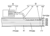
- FIG. 2 is a figure which shows the outline of the air blower with a discharge device concerning the embodiment.
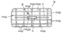
- FIG. 3 is a figure which shows the state which looked at the blower outlet of the air blower with a discharge device concerning the embodiment from the front.
- FIG. 4 is a figure which shows typically the discharge device of the air blower with a discharge device concerning the embodiment.
- FIG. 5 is a diagram schematically illustrating an example of a method of connecting the discharge device according to the embodiment to the blower.
- FIG. 1 is a diagram schematically illustrating an example of a state in which a blower with a discharge device according to an embodiment of the present invention is arranged in a vehicle.
- FIG. 2 is a figure which shows the outline of the air blower with a discharge device concerning the embodiment.
- FIG. 3 is a figure which shows
- FIG. 6 is a diagram schematically illustrating a state in which the discharge device according to the embodiment is connected to the blower.
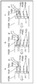
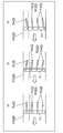
- FIG. 7 is a diagram illustrating a relationship between the opening surface of the introduction pipe and the wind direction adjusting plate according to the embodiment, wherein (a) is a diagram illustrating a state in which the air direction adjusting plate is aligned with the flow of air; (B) is a figure which shows the state which rotated the same wind direction adjustment board to the one side, (c) is a figure which shows the state which rotated the same wind direction adjustment board to the other side.
- FIG. 8 is a diagram showing the relationship between the opening surface of the introduction pipe and the wind direction adjusting plate according to the first modification of the embodiment of the present invention.
- FIG. 8 is a diagram showing the relationship between the opening surface of the introduction pipe and the wind direction adjusting plate according to the first modification of the embodiment of the present invention.
- FIG. 8 (a) shows the air direction adjusting plate along the flow of air flow.
- FIG. 5B is a diagram illustrating a state in which the same wind direction adjusting plate is rotated to one side
- FIG. 5C is a diagram illustrating a state in which the same air direction adjusting plate is rotated to the other side.
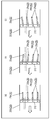
- FIG. 9 is a view showing the relationship between the opening surface of the introduction pipe and the wind direction adjusting plate according to the second modification of the embodiment of the present invention.
- FIG. 9 (a) shows the air direction adjusting plate along the flow of air flow.
- FIG. 5B is a diagram illustrating a state in which the same wind direction adjusting plate is rotated to one side
- FIG. 5C is a diagram illustrating a state in which the same air direction adjusting plate is rotated to the other side. .
- an air conditioner with a discharge device that is installed in the vehicle 1 and has an electrostatic atomizer attached to the vehicle air conditioner will be described as an example of a blower with a discharge device.
- the vehicle air conditioner is an example of a blower.
- the electrostatic atomizer is composed of a discharge unit, a liquid supply unit, and the like, and is an example of a discharge device.
- the electrostatic atomizer generates nanometer-sized charged fine particle water containing radicals as active ingredients.
- FIG. 1 is a diagram schematically illustrating an example of a state in which a blower with a discharge device according to an embodiment of the present invention is arranged in a vehicle.
- FIG. 2 is a figure which shows the outline of the air blower with a discharge device concerning the embodiment.
- FIG. 3 is a figure which shows the state which looked at the blower outlet of the air blower with a discharge device concerning the embodiment from the front.
- the air conditioner with a discharge device 10 of the present embodiment includes a vehicle air conditioner 20 that constitutes a blower, an electrostatic atomizer 30 that constitutes a discharge device, and the like. Installed in the vehicle 1. Specifically, the air conditioner 10 with a discharge device is disposed inside the instrument panel 2 that defines the vehicle compartment 3 (outside the vehicle compartment 3).
- the vehicle air conditioner 20 includes a housing 210 having an inlet 211 and one or more outlets 212.
- the suction port 211 takes in the air outside the vehicle air conditioner 20 to the inside.
- the air outlet 212 includes an effective component described later in the taken-in air and blows it out of the vehicle air conditioner 20.
- the housing 210 is formed using a resin such as PBT (polybutylene terephthalate).
- the housing 210 further includes an air conditioning unit 220, a piping unit 230, and the like.
- the air conditioning unit 220 is connected to the suction port 211 and adjusts, for example, temperature and humidity of the air taken in from the suction port 211.
- the piping unit 230 is connected to the air conditioning unit 220, and has a ventilation path 260 through which air adjusted by the air conditioning unit 220 flows.
- the air conditioning unit 220 includes a blower 21, a filter 22, an evaporator 23, and the like.
- the blower 21 generates a flow of air to be blown.
- the filter 22 removes foreign matter in the sucked air.
- the evaporator 23 adjusts the temperature of the sucked air.
- the suction port 211 of the housing 210 is configured to be switchable so as to selectively communicate with either the outside of the vehicle compartment 3 or the inside of the vehicle compartment 3 by a switching unit (not shown).
- the piping unit 230 further includes a piping main body 240 connected to the air conditioning unit 220, one or more branch pipes 250 connected to the downstream side of the piping main body 240, and the like. That is, the air passage 260 is configured by the air passage main body 270 formed in the pipe main body 240 and the branch passages 280 formed in the respective branch pipes 250. And the blower outlet 212 of the housing 210 is provided in the downstream of the branch path 280 formed in each branch pipe 250.
- the vehicle air conditioner 20 is disposed inside the instrument panel 2 (outside the vehicle compartment 3) in a state where each air outlet 212 communicates with the vehicle compartment 3.
- the vehicle air conditioner 20 having the above configuration first generates an air flow by energizing the blower 21. Thereby, the air outside the vehicle compartment 3 or inside the vehicle compartment 3 is taken into the air conditioning unit 220 from the suction port 211 of the housing 210.
- the air taken into the air conditioning unit 220 passes through the filter 22 to remove foreign substances in the air. Thereafter, the air from which the foreign matter has been removed is introduced into the evaporator 23 and the temperature and the like are adjusted.
- the air whose temperature has been adjusted by the evaporator 23 (hereinafter sometimes referred to as “adjusted air”) is introduced into the air passage 260 and discharged into the vehicle compartment 3 from the air outlet 212 of the housing 210.
- the adjusted air is first introduced from the air conditioning unit 220 into the air duct main body 270.
- the introduced adjusted air passes through the air passage main body 270 and is introduced into the branch passage 280 that branches into one or more.
- the adjusted air introduced into the branch passage 280 is discharged into the vehicle compartment 3 from the air outlet 212 of the housing 210 provided on the downstream side through the branch passage 280.
- a finisher 24 is attached to the air outlet 212 of the housing 210.
- the finisher 24 is formed in a frame shape with, for example, a synthetic resin such as PP (polypropylene), and is attached to the downstream end (the outlet 212) of the branch pipe 250.
- the finisher 24 has a plurality of partition walls 25, for example. Therefore, the blower outlet 212 of the housing 210 is formed with one or more openings 212 a defined by the finisher 24 and the partition wall 25 in a front view of the blower outlet 212.
- the air outlet 212 of the present embodiment has one or more openings 212 a that are at least partially defined by the partition wall 25 in a front view of the air outlet 212.
- the partition wall 25 includes a wind direction adjusting plate 25a that adjusts the wind direction of the air discharged from the air outlet 212.
- the horizontal partition wall 25b is disposed in the finisher 24 so as to extend substantially horizontally (including horizontal).
- the air direction adjusting plate 25a is attached to the upstream side of the horizontal partition wall 25b in the branch passage 280 (in the air blowing passage 260). At this time, the wind direction adjusting plate 25a is rotatably mounted in the branch path 280 around a rotation axis extending substantially vertically (including vertical).
- the opening 212a is defined by the finisher 24, the horizontal partition wall 25b extending in the horizontal direction, and the wind direction adjusting plate 25a extending in the vertical direction.
- Each of the wind direction adjusting plates 25a is connected by a link 27.
- the knob portion 26 is provided on the wind direction adjusting plate 25a located at the center in the longitudinal direction.
- the knob portion 26 is attached to the wind direction adjusting plate 25a so as to be slidable in the left-right direction with a predetermined stroke.
- the wind direction adjusting plate 25a to which the knob portion 26 is attached and the wind direction adjusting plate 25a connected to the wind direction adjusting plate 25a via the link 27 rotate in the left-right direction in conjunction with the left-right operation of the knob portion 26. To do. Thereby, the direction (wind direction) of the wind which blows off into the vehicle interior 3 from the blower outlet 212 of the housing 210 is adjusted right and left.
- the configuration in which the wind direction (wind direction) can be adjusted only in the left-right direction via the knob portion 26 is described as an example, but the configuration is not limited thereto.
- the horizontal partition wall 25b extending in the horizontal direction may be configured to be rotatable about a rotation axis extending substantially vertically (including vertical).
- a rotation axis extending substantially vertically (including vertical).
- the air conditioner 10 with the discharge device which is an example of the blower with the discharge device of the present embodiment, is configured.
- the electrostatic atomizer 30 generates charged fine particle water 40 that is an active ingredient.
- the electrostatic atomizer 30 includes at least a discharge unit 310 and a Peltier unit 320 as shown in FIG.
- the discharge unit 310 includes a discharge electrode 311 constituting a first electrode, a counter electrode 312 constituting a second electrode, and the like.
- the Peltier unit 320 includes a cooling unit 330 and a heat radiating unit 340, and constitutes a liquid supply unit.
- the discharge electrode 311 of the discharge unit 310 is connected to the cooling unit 330 side of the Peltier unit 320 and is configured to be freely cooled by the Peltier unit 320.
- the counter electrode 312 of the discharge unit 310 is provided at the tip of the support frame 350 connected to the Peltier unit 320 and is held by the support frame 350.
- the discharge electrode 311 and the counter electrode 312 of the discharge unit 310 are fixed at positions facing each other at a predetermined interval.
- the counter electrode 312 is not essential, and may be omitted if a configuration capable of applying a high voltage at which discharge occurs to the discharge electrode 311 of the discharge unit 310 is provided.
- the cooling unit 330 of the Peltier unit 320 includes an insulating plate 331, a cooling insulating plate 332, and the like.
- the insulating plate 331 is made of, for example, alumina or aluminum nitride having high thermal conductivity.
- the cooling insulating plate 332 is made of, for example, alumina or aluminum nitride having high thermal conductivity and high electric resistance.
- a circuit 331a is formed on one side of the insulating plate 331 (the lower side in FIG. 4).
- the heat radiation part 340 of the Peltier unit 320 includes an insulating plate 341, a heat radiation plate 342, and the like.
- the insulating plate 341 is made of, for example, alumina or aluminum nitride having high thermal conductivity.
- the heat sink 342 is made of a metal having high thermal conductivity, such as aluminum.
- a circuit 341a is formed on one side of the insulating plate 341 (upper side in FIG. 4).
- one or more heat radiating fins 342a are attached to one side of the heat radiating plate 342 (the lower side in FIG. 4).
- the circuit 331a of the cooling unit 330 and the circuit 341a of the heat dissipation unit 340 are arranged to face each other so as to face each other.
- a number of BiTe-based thermoelectric elements 360 are sandwiched between the opposing circuits 331a and 341a.
- the adjacent thermoelectric elements 360 are electrically connected to the circuits 331a and 341a on both sides.
- the adjacent thermoelectric element 360 is energized via the Peltier input lead wire 370, and heat moves from one side of the cooling unit 330 and the heat radiation unit 340 to the other side.
- the discharge electrode 311 of the discharge unit 310 is cooled, and water vapor or the like in the air condenses on the discharge electrode 311.
- the cooling unit 330 is formed by the cooling-side insulating plate 331 and the cooling insulating plate 332, and the heat-dissipating unit 340 is formed by the heat-dissipating-side insulating plate 341 and the heat-dissipating plate 342. Constitute. Furthermore, heat is transferred from the cooling unit 330 side to the heat radiating unit 340 side via the thermoelectric element 360. Thereby, cooling of the discharge part 310 is enabled.
- the support frame 350 of the discharge device 30 is made of, for example, an insulating material such as PBT resin, polycarbonate, or PPS resin, and is formed in a cylindrical shape having openings that are penetrated at both ends.
- a connecting flange portion 352 to which the heat radiating plate 342 is connected protrudes over the entire periphery.
- a ring-shaped counter electrode 312 integrally formed by insert molding or the like is disposed in the opening on the other end side of the support frame 350.
- the flange portion 352 has one or more screw holes 352a that are provided at equal intervals in the circumferential direction. And the flange part 352 and the peripheral part of the heat sink 342 are screwed with the screw 353 through the screw hole 352a. As a result, the support frame 350 is coupled to the Peltier unit 320.
- the connection method is not limited to screwing, and for example, the support frame 350 may be bonded to the Peltier unit 320 while being bonded with, for example, an epoxy-based adhesive.
- the support frame 350 includes a partition wall 351 extending from the inner peripheral surface toward the center.
- the partition wall 351 divides the internal space of the support frame 350 into a discharge space S1 and a sealing space S2.
- the partition wall 351 has a communication hole 351a formed in the center so as to communicate the discharge space S1 and the sealing space S2.
- the discharge electrode 311 is inserted through the communication hole 351a.
- the discharge electrode 311 of the discharge unit 310 is made of a material having high thermal conductivity and high conductivity, such as aluminum, copper, tungsten, titanium, and stainless steel.
- the discharge electrode 311 includes a main body part 311a and a sandwiched part 311c having a larger diameter than the main body part 311a, which are formed in a columnar shape.
- the main body 311a is formed with a smaller diameter (including the same diameter) than the diameter of the communication hole 351a of the partition wall 351, and has, for example, a sharp discharge extreme portion 311b at the tip (on the counter electrode 312 side).
- the sandwiched portion 311c is provided on the base end side (Peltier unit 320 side) of the main body portion 311a and is formed with a diameter larger than the diameter of the communication hole 351a of the partition wall 351.
- the main body 311 a of the discharge electrode 311 is fitted into the communication hole 351 a of the partition wall 351.
- the Peltier unit 320 is coupled to the support frame 350.
- the main body portion 311a of the discharge electrode 311 is disposed in the discharge space S1 on the extreme discharge portion 311b side, and the sandwiched portion 311c of the discharge electrode 311 is disposed in the sealing space S2.
- the sandwiched portion 311 c of the discharge electrode 311 is sandwiched between the partition wall 351 of the support frame 350 and the cooling insulating plate 332 of the Peltier unit 320.
- the sandwiched portion 311c of the discharge electrode 311 is pressed toward the cooling unit 330 side of the Peltier unit 320, and the sandwiched unit 311c and the cooling unit 330 are connected.
- the support frame 350 functions as a clamping member that fixes the cooling unit 330 and the discharge electrode 311 of the Peltier unit 320 in a connected state.
- the support frame 350 also functions as a sealing member that holds the circuit 331a, 341a and the thermoelectric element 360 inside the Peltier unit 320 in a sealed state so that moisture does not enter.
- the space between the cooling insulating plate 332 and the partition 351 of the Peltier unit 320 and the upper surface of the partition 351 are sealed with a sealing resin 390 made of, for example, an epoxy resin.
- a sealing resin 390 made of, for example, an epoxy resin.
- the sealing with the sealing resin 390 is not limited between the support frame 350 and the cooling insulating plate 332 or between the support frame 350 and the discharge electrode 311 as shown in FIG.
- the sealing resin 390 may be provided so that the inside of the Peltier unit 320 is filled and sealed.
- the main body 311 a of the discharge electrode 311 is connected to one end side of the high-voltage lead wire 381 in the discharge space S 1 of the support frame 350.
- the other end side of the high-voltage lead wire 381 is pulled out of the support frame 350 and connected to the high voltage application unit 380.
- the high-voltage lead 381 is formed using, for example, a metal such as copper or a conductive plastic.
- the high voltage application unit 380 electrically connected to the discharge electrode 311 via the high-voltage lead 381 is electrically connected to the counter electrode 312 disposed above the support frame 350. Thereby, a high voltage generated by the high voltage application unit 380 is applied between the discharge electrode 311 and the counter electrode 312. As a result, a discharge that generates an active component can be generated between the discharge electrode 311 and the counter electrode 312.
- the electrostatic atomizer 30 which is an example of the discharge device of the air conditioner 10 with a discharge device is comprised.
- thermoelectric element 360 in a sealed state is connected via the Peltier input lead wire 370 by the connection of the support frame 350 and the heat radiating plate 342.
- the energization causes heat to move in the same direction in each thermoelectric element 360.
- the discharge electrode 311 is cooled by the heat transfer through the cooling unit 330 connected to the cooling side of the thermoelectric element 360.
- the air around the discharge electrode 311 is cooled in the discharge space S1 of the support frame 350.
- moisture such as water vapor in the air is liquefied due to condensation, and water is generated on the surface of the discharge electrode 311.
- a high voltage is applied between the discharge electrode 311 and the counter electrode 312 by the high voltage application unit 380 in a state where water is generated and held in the discharge extreme 311 b of the discharge electrode 311.
- the high voltage application unit 380 applies a high voltage so that the discharge extreme portion 311b side of the discharge electrode 311 becomes a negative electrode and charges are concentrated.
- the water held in the discharge extreme part 311b receives large energy and repeats Rayleigh splitting.
- a large amount of nanometer-sized charged fine particle water 40 which is the active ingredient described above, is generated.
- the generated charged fine particle water 40 moves toward the counter electrode 312 facing the discharge electrode 311.
- the charged particulate water 40 passes through the mist discharge port 312a and is discharged to the outside of the electrostatic atomizer 30 (in the vehicle compartment 3 in the present embodiment).
- the charged fine particle water 40 generated by the electrostatic atomizer 30 includes radicals such as superoxide radicals and hydroxy radicals. These radicals have effects such as deodorization, suppression of viruses and molds, and inactivation of allele substances. Therefore, for example, if the charged fine particle water 40 containing radicals is released into the passenger compartment 3, the odor components in the air in the passenger compartment 3 and the odor components adhering to the wall surfaces and sheets in the passenger compartment 3 are deodorized. be able to. Furthermore, it is possible to suppress allergens such as pollen that are brought into the passenger compartment 3 by adhering to human clothes.
- radicals such as superoxide radicals and hydroxy radicals.
- the electrostatic atomizer is described as an example of the discharge device, but is not limited thereto.
- an ion generator that generates air ions such as negative ions or / and positive ions instead of the charged fine particle water instead of the Peltier unit that constitutes the liquid supply unit may be used as the discharge device.
- the ion generator generates hydroxy radicals and the like.
- the electrostatic atomizer 30 operates and exerts the above actions and effects.
- the blower with discharge device includes at least one branch path among the branch paths 280 that branch the air containing the charged fine particle water 40 generated by the electrostatic atomizer 30 into one or more. It is comprised so that it may discharge
- a configuration in which the electrostatic atomizer 30 is arranged in the branch path 280 can be considered. That is, the charged fine particle water 40 is generated by the electrostatic atomizer 30 arranged in the branch path 280, and the charged fine particle water 40 is put on the air flow R1 (see FIG. 6) in the branch path 280. Thereby, the structure which diffuses the charged fine particle water 40 in the vehicle interior 3 can be considered.
- the electrostatic atomizer 30 when the electrostatic atomizer 30 is arranged in the air passage 260 of the vehicle air conditioner 20 including devices such as the evaporator 23 and the blower 21, the air adjusted by the air conditioner 220 (high-temperature air and / or The electrostatic atomizer 30 is exposed to air of low humidity.
- the water supplied to the discharge electrode 311 for electrostatic atomization may evaporate by the adjusted air. Therefore, the electrostatic atomization by the discharge of water may be inhibited.
- the electrostatic atomizer 30 cools the discharge electrode 311 to condense moisture in the air, and generates water for electrostatic atomization on the discharge electrode 311. That is, the electrostatic atomizer 30 of the above type is excellent in usability in that it does not require water supply. However, as described above, when the electrostatic atomizer 30 is exposed to the adjusted air, there is a possibility that condensed water cannot be stably generated on the discharge electrode.
- the electrostatic atomizer 30 is arranged outside the blower passage 260, that is, outside the piping part 230. Thereby, it is suppressed that the electrostatic atomizer 30 is exposed to the adjusted high temperature air and the low humidity air which flow through the inside of the ventilation path 260. Therefore, the electrostatic atomizer 30 can generate the charged fine particle water 40 efficiently without being affected by the adjusted air flowing in the air passage 260.
- FIG. 5 is a diagram schematically illustrating an example of a method of connecting the discharge device according to the embodiment to the blower.
- FIG. 6 is a diagram schematically illustrating a state in which the discharge device according to the embodiment is connected to the blower.
- the electrostatic atomizer 30 of the present embodiment is connected to the inside of the branch passage 280 (the air passage 260) through the introduction pipe 50.
- one end 51 of the introduction pipe 50 is connected to the electrostatic atomizer 30 that is included in, for example, one branch pipe 250 that configures the piping section 230.
- the other end 52 of the introduction pipe 50 is disposed in a branch path 280 (blower path 260) configured inside the branch pipe 250 via the branch pipe 250.
- the introduction pipe 50 is formed using a resin such as PP (polypropylene).
- the other end 52 side of the introduction pipe 50 is disposed so as to enter into the branch passage 280 (blower passage 260) in the vicinity of the outlet 212.
- the branch passage 280 (blower passage 260) in the vicinity of the outlet 212.
- most of the portion of the introduction pipe 50 that enters the branch passage 280 is arranged in parallel, for example, along the air flow R1 flowing in the branch passage 280.
- the opening surface 50 a formed at the end portion on the other end 52 side of the introduction pipe 50 is disposed at a position in the vicinity of the upstream side of the wind direction adjusting plate 25 a constituting the partition wall 25.
- the introduction pipe 50 is preferably configured so that the inner surface is smoothly formed and can be bent in a curved manner.
- the length of the introduction pipe 50 is preferably 50 cm or less.
- the branch pipe 250 (pipe section 230) of the present embodiment has an opening 291 formed in the middle.
- the opening 291 is closed by a lid 290 provided on the introduction pipe 50.
- the lid 290 includes a penetrating portion 293 that allows the introduction tube 50 to pass therethrough, and a holding rib 292 that holds the distal end side (the other end 52 side) of the introduction tube 50.
- the introduction tube 50 is held by the holding rib 292 with the distal end side (the other end 52 side) penetrating the penetration portion 293.
- the opening 291 of the branch pipe 250 is closed with the lid 290.
- the holding rib 292 and the like are not shown, but as shown in FIG. 6, the introduction pipe 50 has an air flow R ⁇ b> 1 flowing in the branch path 280, most of the portion entering the branch path 280. It is arranged along.
- the introduction pipe 50 is held by the lid 290 in a state in which a straight line or a smooth curve is drawn between both ends. Thereby, generation
- the charged fine particle water 40 generated by the electrostatic atomizer 30 can be introduced into the branch path 280 more efficiently.
- the introduction pipe 50 of the present embodiment is arranged such that the other end 52 side is along the air flow R1 flowing in the branch path 280. Further, the opening surface 50 a of the introduction pipe 50 is arranged at a position in the vicinity of the upstream side of the wind direction adjusting plate 25 a that constitutes the partition wall 25.
- the opening surface 50a of the introduction pipe 50 is disposed in one opening 212a among the one or more openings 212a in the front view of the air outlet 212 shown in FIG. In this case, it is more preferable to arrange the opening surface 50a of the introduction pipe 50 at the center position of the opening 212a.
- the blower with a discharge device includes the turnable wind direction adjusting plate 25a constituting the partition wall 25 as described above. Therefore, the opening surface 50a of the introduction pipe 50 is disposed at the center position of one opening 212a among the one or more openings 212a in the front view of the air outlet 212 in a state where the air direction adjusting plate 25a is adjusted. That's fine.
- the state which adjusted the wind direction adjustment board 25a is a state in which the wind direction of the air discharge
- the opening surface 50a of the introduction pipe 50 is, for example, the center position of the opening 212a in a state where the side surface 25a1 of the wind direction adjusting plate 25a formed in a spindle shape or the like is along the air flow R1 flowing in the branch passage 280. Should be arranged.
- the introduction pipe 50 of the present embodiment is formed in the shape of the inclined portion 53 whose outer diameter increases from the opening surface 50a side of the other end 52 toward the one end 51 side. Thereby, the diameter of the other end 52 of the introduction pipe 50 is reduced so as not to overlap with the air direction adjusting plate 25a.
- the other end 52 of the introduction pipe 50 has a size that can be accommodated in the opening 212a in a front view. As a result, it is possible to prevent obstruction of the flow of air discharged from the introduction pipe 50 by the wind direction adjusting plate 25a.
- the introduction pipe 50 of the present embodiment has a maximum outer diameter in the branch path 280 of, for example, 12 mm or less.
- the loss of the air volume which flows in the branch path 280 caused by the introduction pipe 50 provided in the branch path 280 can be suppressed.
- the effect of suppressing the loss of air volume is determined by the ratio between the outer diameter of the introduction pipe 50 and the diameter of the branch pipe 250. Therefore, the above numerical value is an example of a preferable value for the branch pipe 250 made of a rectangle having a vertical and horizontal dimensions of, for example, about 100 mm to 180 mm when the vehicle is mounted in this embodiment. That is, the branch pipe 250 may have a circular shape having an inner diameter of about 100 mm to 150 mm. Therefore, the preferable maximum outer diameter of the introduction pipe 50 is changed depending on the shape, dimensions, and the like.
- the inner diameter on the one end 51 side of the introduction pipe 50 of the present embodiment is preferably about 10 mm, for example.
- the inner diameter of 10 mm is a value set assuming that the tube thickness is 1 mm when the outer diameter is 12 mm. Therefore, it goes without saying that the present invention is not limited to the above numerical values.
- the air direction of the air conditioning can be changed in the vertical direction and the left and right direction by inclining the wind direction adjusting plate 25a with respect to the air flow R1. .
- the area of the opening 212a (the area of the portion communicating with the air passage 260 in the front view of the air outlet 212) decreases. Therefore, in the front view of the blower outlet 212, there exists a possibility that the opening surface 50a of the introduction pipe 50 may overlap with the wind direction adjusting plate 25a.
- the inner diameter of the introduction pipe 50 on the opening surface 50a side is preferably about 3 mm or more and 80% or less of the pitch of the wind direction adjusting plate 25a.
- the electrostatic atomizer 30 is connected to the air passage 260 through the introduction pipe 50.
- the vehicle air conditioner 20 having the above configuration first generates an air flow by energizing the blower 21. Thereby, the air outside the vehicle compartment 3 or inside the vehicle compartment 3 is taken into the air conditioning unit 220 from the suction port 211 of the housing 210.
- the air taken into the air conditioning unit 220 passes through the filter 22 to remove foreign substances in the air. Thereafter, the air from which the foreign matter has been removed is introduced into the evaporator 23 and the temperature and the like are adjusted.
- the air whose temperature has been adjusted by the evaporator 23 (adjusted air having viscosity) is introduced from the air conditioning unit 220 into the air duct main body 270.
- the introduced air passes through the air passage main body 270 and is introduced into one or more branch paths 280.
- the air introduced into the branch path 280 passes through the branch path 280 and is discharged into the vehicle compartment 3 from the air outlet 212 of the housing 210 provided on the downstream side.
- the introduction pipe 50 of the present embodiment is arranged so that the other end 52 side is along the air flow R1 flowing in the branch path 280. Further, the opening surface 50 a of the introduction pipe 50 is disposed at a position in the vicinity of the upstream side of the wind direction adjusting plate 25 a constituting the partition wall 25.
- the opening surface 50a of the introduction pipe 50 is disposed in one opening 212a among the one or more openings 212a in a front view of the air outlet 212 shown in FIG. That is, the opening surface 50a on the other end 52 side of the introduction pipe 50 is disposed at the position of the opening 212a that does not overlap the rotating air direction adjusting plate 25a.
- the opening 212a in the vicinity of the wind direction adjusting plate 25a is a region where the air resistance that obstructs the flow of air flowing through the branch path 280 is relatively small. Therefore, when the opening surface 50a of the introduction pipe 50 is disposed in the opening 212a in the vicinity of the wind direction adjusting plate 25a, more air flows toward the opening 212a around the vicinity of the other end 52 of the introduction pipe 50. be able to. Then, the air containing the charged fine particle water 40 in the introduction pipe 50 is attracted into the branch path 280 by the air flow. Thereby, the charged fine particle water 40 generated by the electrostatic atomizer 30 flows into the branch path 280 more efficiently.
- the air containing the charged fine particle water 40 in the introduction pipe 50 is attracted and merges with the air flowing through the branch path 280.
- the adjusted air containing the charged fine particle water 40 passes through the wind direction adjusting plate 25 a installed at the outlet 212 and diffuses out of the vehicle air conditioner 20. In the case of the present embodiment, the adjusted air containing the charged fine particle water 40 is diffused into the vehicle interior 3.
- the configuration in which the electrostatic atomizer 30 and the introduction pipe 50 are arranged in one branch path 280 among the one or more branch paths 280 is described as an example. Not limited to.
- the electrostatic atomizer 30 and the introduction pipe 50 are arranged in each of the one or more branch paths 280 so that the adjusted air containing the charged fine particle water 40 is discharged from the respective outlets 212. It may be configured. Thereby, the charged fine particle water 40 generated by the electrostatic atomizer 30 can be discharged from the respective outlets 212. Therefore, the effects of the charged fine particle water 40 such as the deodorization described above can be obtained in a short time.
- the blower 10 with the discharge device is provided outside the air passage 260 having the air outlet 212 that releases air and the air passage 260 that generates the charged fine particle water 40 that is an active component.
- An electrostatic atomizer 30 discharge device
- the blower with discharge device 10 is introduced such that one end 51 is connected to the electrostatic atomizer 30 and the other end 52 side is disposed in the blower passage 260 to guide the charged particulate water 40 into the branch passage 280.
- a tube 50 is provided.
- the air outlet 212 has one or more openings 212a at least partially defined by the partition wall 25 in a front view of the air outlet 212, and the introduction pipe 50 has an opening surface 50a on the other end 52 side. Have.
- the other end 52 side of the introduction pipe 50 is disposed along the air flow R ⁇ b> 1 in the air passage 260, and the opening surface 50 a is in the vicinity of the upstream side of the partition wall 25 and at least one or more openings in the front view of the air outlet 212. It arrange
- the charged fine particle water 40 generated by the electrostatic atomizer 30 which is an example of the discharge device is more efficiently caused to flow into the branch path 280. be able to.
- the introduction pipe 50 is extended so that the opening surface 50a on the other end 52 side is close to the air outlet 212. Furthermore, the opening surface 50 a of the introduction pipe 50 is disposed at a position where a negative pressure is likely to be generated at the air outlet 212, that is, a position where it does not overlap with the wind direction adjusting plate 25 a constituting the partition wall 25. Therefore, the charged fine particle water 40 which is an active ingredient can be attracted more efficiently using negative pressure, and can be sent to the outside from the outlet 212. Thereby, it is not necessary to provide in particular the ventilation part for forcibly sending out the charged fine particle water 40 in the electrostatic atomizer 30 itself. As a result, it is possible to reduce the cost while simplifying the configuration of the blower with the discharge device.
- a blower such as a fan may be added to the electrostatic atomizer 30 itself in the present embodiment.
- the addition of the air blowing unit may cause vibration or abnormal noise, for example.
- the blower with discharge device 10 of the present embodiment has a configuration in which the blower of the electrostatic atomizer 30 itself is omitted. Thereby, generation
- the opening surface 50a of the introduction tube 50 is centered on one opening 212a among the one or more openings 212a in the front view of the air outlet 212. Placed in position. Thereby, it can suppress more reliably that the flow of the air in the ventilation path 260 which flows the circumference
- the blower 10 with the discharge device includes a partition wall 25 inside the air passage 260, and the partition wall 25 includes a wind direction adjusting plate 25a that adjusts the wind direction of the air discharged from the air outlet 212.
- the blower 10 with the discharge device capable of adjusting the wind direction, it is possible to suppress the air flow in the air passage 260 flowing around the introduction tube 50 from being obstructed by the wind direction adjusting plate 25a. As a result, the air in the introduction pipe 50 can be efficiently attracted into the air blowing path 260.
- the blower 10 with the discharge device is in a state in which the wind direction adjusting plate 25a is adjusted so that the wind direction of the air discharged from the blower outlet 212 is in a direction perpendicular to the opening 212a of the blower outlet 212.
- the opening surface 50a of the introduction pipe 50 is disposed at the center position of one opening 212a among the one or more openings 212a.
- the wind direction adjusting plate 25a can be configured to be rotatable at an arbitrary position using FIGS.
- FIGS. 7A to 7C illustrate the relationship between the opening surface 50a of the introduction tube 50 and the airflow direction adjusting plate 25a that are rotated with the position of the central portion of the airflow direction adjusting plate 25a as the rotation center. is doing.
- the relationship with 25a is illustrated.
- FIGS. 9A to 9C the opening surface 50a of the introduction pipe 50 and the airflow direction adjusting plate in a rotated state with the upstream position of the airflow direction adjusting plate 25a as the rotation center.
- the relationship with 25a is illustrated.
- the opening surface 50a of the introduction pipe 50 is arranged at the center position of the opening 212a, the inside of the air passage 260 is caused by the change of the inclination due to the rotation of the wind direction adjusting plate 25a.
- the movable (turning) range of the wind direction adjusting plate 25a can be increased as much as possible within a range that does not hinder the air flow in the air passage 260.
- the air discharged from the air outlet 212 can be discharged in a wider range.
- the introduction tube 50 is configured by an inclined portion 53 whose outer diameter increases from the opening surface 50a side toward the one end 51 side.
- the outer diameter of the inlet tube 50 becomes large. Therefore, the charged fine particle water 40 generated by the electrostatic atomizer 30 can be more reliably guided into the introduction pipe 50.
- the outer diameter of the introduction pipe 50 is reduced. Therefore, it can suppress as much as possible that the flow of the air in the introductory pipe 50 is inhibited by the wind direction adjusting plate 25a.
- the structure which attaches an electrostatic atomizer to ventilation apparatuses other than a vehicle air conditioner may be sufficient.
- areas, such as a consumer and a house may be sufficient.
- areas, such as a consumer, a vehicle-mounted, a house is also possible.
- a conventionally well-known thing can be used as an air blower or a discharge device.
- the introduction pipe, the air passage, and other detailed specifications are not particularly mentioned, but it is needless to say that they can be changed as appropriate.
- the present invention is useful in the field of a blower with a discharge device that can introduce an active ingredient into a blower path more efficiently.
Landscapes
- Engineering & Computer Science (AREA)
- Mechanical Engineering (AREA)
- Health & Medical Sciences (AREA)
- Animal Behavior & Ethology (AREA)
- Public Health (AREA)
- Combustion & Propulsion (AREA)
- General Engineering & Computer Science (AREA)
- Thermal Sciences (AREA)
- Epidemiology (AREA)
- Life Sciences & Earth Sciences (AREA)
- Physics & Mathematics (AREA)
- General Health & Medical Sciences (AREA)
- Chemical & Material Sciences (AREA)
- Veterinary Medicine (AREA)
- Electrostatic Spraying Apparatus (AREA)
- Air Humidification (AREA)
- Air-Flow Control Members (AREA)
- Air-Conditioning For Vehicles (AREA)
- Disinfection, Sterilisation Or Deodorisation Of Air (AREA)
- Air Filters, Heat-Exchange Apparatuses, And Housings Of Air-Conditioning Units (AREA)
Abstract
La présente invention concerne une soufflante dotée d'un dispositif d'évacuation comprenant : un passage d'écoulement d'air présentant une sortie (212) ; un dispositif d'évacuation disposé à l'extérieur du passage d'écoulement d'air ; et un tuyau d'introduction (50) présentant une extrémité raccordée au dispositif d'évacuation et l'autre extrémité étant raccordée à l'intérieur du passage d'écoulement d'air. La sortie (212) présente une ou plusieurs ouvertures (212a), et le tuyau d'introduction (50) présente une surface d'ouverture (50a) au niveau de l'autre extrémité de celui-ci. L'autre côté d'extrémité du tuyau d'introduction (50) est disposé le long de l'écoulement d'air dans le passage d'écoulement d'air. La surface d'ouverture (50a) est disposée, sur le côté amont d'une paroi de séparation (25), dans l'une des ouvertures (212a). Il est ainsi possible d'introduire plus efficacement une matière active dans le passage d'écoulement d'air.
Applications Claiming Priority (2)
| Application Number | Priority Date | Filing Date | Title |
|---|---|---|---|
| JP2016-168038 | 2016-08-30 | ||
| JP2016168038A JP6624569B2 (ja) | 2016-08-30 | 2016-08-30 | 放電装置付送風装置 |
Publications (1)
| Publication Number | Publication Date |
|---|---|
| WO2018043221A1 true WO2018043221A1 (fr) | 2018-03-08 |
Family
ID=61301246
Family Applications (1)
| Application Number | Title | Priority Date | Filing Date |
|---|---|---|---|
| PCT/JP2017/030019 Ceased WO2018043221A1 (fr) | 2016-08-30 | 2017-08-23 | Soufflante comprenant un dispositif d'évacuation |
Country Status (2)
| Country | Link |
|---|---|
| JP (1) | JP6624569B2 (fr) |
| WO (1) | WO2018043221A1 (fr) |
Cited By (1)
| Publication number | Priority date | Publication date | Assignee | Title |
|---|---|---|---|---|
| CN118960101A (zh) * | 2024-10-14 | 2024-11-15 | 江苏中凯暖通设备有限公司 | 一种具有气味控制机构的空调 |
Families Citing this family (1)
| Publication number | Priority date | Publication date | Assignee | Title |
|---|---|---|---|---|
| JP2021133261A (ja) * | 2020-02-21 | 2021-09-13 | パナソニックIpマネジメント株式会社 | 静電噴霧用組成物および静電噴霧装置 |
Citations (5)
| Publication number | Priority date | Publication date | Assignee | Title |
|---|---|---|---|---|
| JPS62155122A (ja) * | 1985-12-27 | 1987-07-10 | Hitachi Ltd | 自動車用空気調和装置 |
| JPH06115347A (ja) * | 1992-10-02 | 1994-04-26 | Nippondenso Co Ltd | 空気調和装置 |
| JP2010042749A (ja) * | 2008-08-12 | 2010-02-25 | Nissan Motor Co Ltd | 芳香制御装置 |
| JP2011038747A (ja) * | 2009-08-18 | 2011-02-24 | Panasonic Electric Works Co Ltd | 放電装置を備えた送風装置 |
| JP2011084273A (ja) * | 2011-01-17 | 2011-04-28 | Panasonic Electric Works Co Ltd | 静電霧化装置を備えた空調装置 |
-
2016
- 2016-08-30 JP JP2016168038A patent/JP6624569B2/ja active Active
-
2017
- 2017-08-23 WO PCT/JP2017/030019 patent/WO2018043221A1/fr not_active Ceased
Patent Citations (5)
| Publication number | Priority date | Publication date | Assignee | Title |
|---|---|---|---|---|
| JPS62155122A (ja) * | 1985-12-27 | 1987-07-10 | Hitachi Ltd | 自動車用空気調和装置 |
| JPH06115347A (ja) * | 1992-10-02 | 1994-04-26 | Nippondenso Co Ltd | 空気調和装置 |
| JP2010042749A (ja) * | 2008-08-12 | 2010-02-25 | Nissan Motor Co Ltd | 芳香制御装置 |
| JP2011038747A (ja) * | 2009-08-18 | 2011-02-24 | Panasonic Electric Works Co Ltd | 放電装置を備えた送風装置 |
| JP2011084273A (ja) * | 2011-01-17 | 2011-04-28 | Panasonic Electric Works Co Ltd | 静電霧化装置を備えた空調装置 |
Cited By (1)
| Publication number | Priority date | Publication date | Assignee | Title |
|---|---|---|---|---|
| CN118960101A (zh) * | 2024-10-14 | 2024-11-15 | 江苏中凯暖通设备有限公司 | 一种具有气味控制机构的空调 |
Also Published As
| Publication number | Publication date |
|---|---|
| JP6624569B2 (ja) | 2019-12-25 |
| JP2018035977A (ja) | 2018-03-08 |
Similar Documents
| Publication | Publication Date | Title |
|---|---|---|
| JP4470710B2 (ja) | 車両用空気調和装置 | |
| EP1980433B1 (fr) | Systeme de climatisation avec fonction de vaporisation electrostatique | |
| JP4396672B2 (ja) | 車両用静電霧化装置 | |
| JP4864753B2 (ja) | 車両用空調装置 | |
| JP2011038747A (ja) | 放電装置を備えた送風装置 | |
| TW200817097A (en) | Electrostatically atomizing device | |
| JP5368844B2 (ja) | 静電霧化装置を備えた空調装置 | |
| CN102272531A (zh) | 包含放电发生器的空调器的室内机 | |
| JP2011007443A (ja) | 静電霧化装置を備えた送風装置 | |
| JP2007163109A (ja) | 静電霧化装置を備えた空調装置 | |
| WO2018043221A1 (fr) | Soufflante comprenant un dispositif d'évacuation | |
| JP2008133980A (ja) | 空気清浄機能付き空気調和機 | |
| JP4492602B2 (ja) | 車両用静電霧化装置 | |
| JP5301798B2 (ja) | 空気調和機 | |
| JP4966169B2 (ja) | 送風装置 | |
| JP5834211B2 (ja) | 送風装置 | |
| CN109641509B (zh) | 带放电装置的送风装置 | |
| JP5513787B2 (ja) | 放電装置 | |
| JP4824520B2 (ja) | 静電霧化装置 | |
| JP5411881B2 (ja) | 静電霧化装置を備えた空調装置 | |
| JP2007161213A (ja) | 静電霧化装置を備えた空調装置 | |
| JP5919557B2 (ja) | 送風装置 | |
| JP2011191052A (ja) | 静電霧化装置 | |
| JP2013149532A (ja) | イオン送出装置及びイオン発生装置 | |
| HK1121999A (en) | Air conditioning system with electrostatic atomizing function |
Legal Events
| Date | Code | Title | Description |
|---|---|---|---|
| 121 | Ep: the epo has been informed by wipo that ep was designated in this application |
Ref document number: 17846226 Country of ref document: EP Kind code of ref document: A1 |
|
| NENP | Non-entry into the national phase |
Ref country code: DE |
|
| 122 | Ep: pct application non-entry in european phase |
Ref document number: 17846226 Country of ref document: EP Kind code of ref document: A1 |