WO2018043233A1 - Module de cellule solaire, son mode d'encapsulation, et dispositif de production d'énergie solaire - Google Patents
Module de cellule solaire, son mode d'encapsulation, et dispositif de production d'énergie solaire Download PDFInfo
- Publication number
- WO2018043233A1 WO2018043233A1 PCT/JP2017/030056 JP2017030056W WO2018043233A1 WO 2018043233 A1 WO2018043233 A1 WO 2018043233A1 JP 2017030056 W JP2017030056 W JP 2017030056W WO 2018043233 A1 WO2018043233 A1 WO 2018043233A1
- Authority
- WO
- WIPO (PCT)
- Prior art keywords
- solar cell
- cell module
- corner
- cell panel
- block
- Prior art date
- Legal status (The legal status is an assumption and is not a legal conclusion. Google has not performed a legal analysis and makes no representation as to the accuracy of the status listed.)
- Ceased
Links
Images








Classifications
-
- B—PERFORMING OPERATIONS; TRANSPORTING
- B65—CONVEYING; PACKING; STORING; HANDLING THIN OR FILAMENTARY MATERIAL
- B65D—CONTAINERS FOR STORAGE OR TRANSPORT OF ARTICLES OR MATERIALS, e.g. BAGS, BARRELS, BOTTLES, BOXES, CANS, CARTONS, CRATES, DRUMS, JARS, TANKS, HOPPERS, FORWARDING CONTAINERS; ACCESSORIES, CLOSURES, OR FITTINGS THEREFOR; PACKAGING ELEMENTS; PACKAGES
- B65D85/00—Containers, packaging elements or packages, specially adapted for particular articles or materials
-
- H—ELECTRICITY
- H02—GENERATION; CONVERSION OR DISTRIBUTION OF ELECTRIC POWER
- H02S—GENERATION OF ELECTRIC POWER BY CONVERSION OF INFRARED RADIATION, VISIBLE LIGHT OR ULTRAVIOLET LIGHT, e.g. USING PHOTOVOLTAIC [PV] MODULES
- H02S20/00—Supporting structures for PV modules
- H02S20/20—Supporting structures directly fixed to an immovable object
- H02S20/22—Supporting structures directly fixed to an immovable object specially adapted for buildings
- H02S20/23—Supporting structures directly fixed to an immovable object specially adapted for buildings specially adapted for roof structures
-
- H—ELECTRICITY
- H02—GENERATION; CONVERSION OR DISTRIBUTION OF ELECTRIC POWER
- H02S—GENERATION OF ELECTRIC POWER BY CONVERSION OF INFRARED RADIATION, VISIBLE LIGHT OR ULTRAVIOLET LIGHT, e.g. USING PHOTOVOLTAIC [PV] MODULES
- H02S30/00—Structural details of PV modules other than those related to light conversion
-
- H—ELECTRICITY
- H02—GENERATION; CONVERSION OR DISTRIBUTION OF ELECTRIC POWER
- H02S—GENERATION OF ELECTRIC POWER BY CONVERSION OF INFRARED RADIATION, VISIBLE LIGHT OR ULTRAVIOLET LIGHT, e.g. USING PHOTOVOLTAIC [PV] MODULES
- H02S40/00—Components or accessories in combination with PV modules, not provided for in groups H02S10/00 - H02S30/00
-
- Y—GENERAL TAGGING OF NEW TECHNOLOGICAL DEVELOPMENTS; GENERAL TAGGING OF CROSS-SECTIONAL TECHNOLOGIES SPANNING OVER SEVERAL SECTIONS OF THE IPC; TECHNICAL SUBJECTS COVERED BY FORMER USPC CROSS-REFERENCE ART COLLECTIONS [XRACs] AND DIGESTS
- Y02—TECHNOLOGIES OR APPLICATIONS FOR MITIGATION OR ADAPTATION AGAINST CLIMATE CHANGE
- Y02B—CLIMATE CHANGE MITIGATION TECHNOLOGIES RELATED TO BUILDINGS, e.g. HOUSING, HOUSE APPLIANCES OR RELATED END-USER APPLICATIONS
- Y02B10/00—Integration of renewable energy sources in buildings
- Y02B10/10—Photovoltaic [PV]
-
- Y—GENERAL TAGGING OF NEW TECHNOLOGICAL DEVELOPMENTS; GENERAL TAGGING OF CROSS-SECTIONAL TECHNOLOGIES SPANNING OVER SEVERAL SECTIONS OF THE IPC; TECHNICAL SUBJECTS COVERED BY FORMER USPC CROSS-REFERENCE ART COLLECTIONS [XRACs] AND DIGESTS
- Y02—TECHNOLOGIES OR APPLICATIONS FOR MITIGATION OR ADAPTATION AGAINST CLIMATE CHANGE
- Y02E—REDUCTION OF GREENHOUSE GAS [GHG] EMISSIONS, RELATED TO ENERGY GENERATION, TRANSMISSION OR DISTRIBUTION
- Y02E10/00—Energy generation through renewable energy sources
- Y02E10/50—Photovoltaic [PV] energy
Definitions
- the present invention relates to a solar cell module, its packing form, and a solar power generation device using the same.
- a solar cell module including a solar cell panel including a plurality of photoelectric conversion elements and a metal frame fixed to a peripheral portion of the solar cell panel.
- Such a solar cell module is generally installed on the roof using the frame.
- a so-called frameless solar cell panel in which the frame is not provided is also known (see Patent Document 1). Cost reduction can be achieved by not providing the frame on the solar cell panel.
- a sealing material, a glass substrate, or the like constituting the solar cell panel may be exposed at the peripheral portion.
- the corner of the solar cell panel that exhibits a rectangular shape (square shape, rectangular shape, pentagonal shape, etc.) in plan view, in particular.
- the glass substrate and the sealing material are easily damaged due to the impact on the part.
- the solar cell module which is one mode of the present disclosure includes a solar cell panel having a corner shape in a plan view, and a plurality of corner blocks fixed to cover each corner portion of the solar cell panel.
- a photovoltaic power generation apparatus is arranged in parallel with each other along a plurality of first rods arranged in parallel with each other along a first direction and a direction orthogonal to the first direction.
- a solar cell module installed on a rectangular frame constituted by a support structure including a plurality of second ridges whose both ends are respectively connected to the first ridges, and the first ridge and the second ridge The solar cell module is supported by placing the lower surface of the corner block on the inner bottom surface of the first rod.
- a photovoltaic power generation apparatus includes a lower frame having a substantially U-shaped cross section, two vertical frames having a substantially U-shaped cross section standing on both ends of the lower frame, and two A vertically installed rectangular frame including an upper cover attached in parallel with the lower frame over each upper end of the vertical frame, and a solar cell module according to the present disclosure installed in a state where the periphery is supported by the rectangular frame.
- the corner block comes into contact with the inner surface of the vertical frame.
- the corner block is fixed so as to cover the corner portion of the solar cell panel. It is possible to prevent damage to the corners.
- FIG. 1 It is a figure which shows the packing form of the solar cell module which is an example of embodiment, (a) is a top view, (b) is AA sectional drawing in (a), (c) is B in (a). It is an arrow view. It is a figure which shows the corner block which is an example of embodiment, (a) is a top view, (b) is a front view, (c) is a side view.
- (A)-(c) is a figure which shows a mode that a 2 part type
- (A)-(c) is a figure which shows a mode that the integrated corner block shown in FIG. 2 is attached to a solar cell panel.
- FIG. 9 is a side view which shows the state by which the spacer member is arrange
- (b) is an E arrow directional view in (a).
- FIG. (A) is a figure which shows the state which installed the frameless solar cell panel in the support structure shown in FIG. (A) is a figure which shows a mode that the packing member has been arrange
- FIG. 17 shows the example which connected the height adjustment member to the lower surface of a corner block.
- FIG. 17 shows the example which connected the height adjustment member to the lower surface of a corner block.
- FIG. 17 shows the example which connected the height adjustment member to the lower surface of a corner block.
- FIG. 17 shows the example which connected the height adjustment member to the lower surface of a corner block.
- It is (a) top view, (b) front view, and (c) side view showing a corner block of a third modification.
- FIG. 17 shows the state in which the solar cell module which has the corner block shown in FIG. 19 was installed in the support structure shown in FIG.
- FIG. 22 It is a figure which shows a mode that a vertical installation type solar power generation device is installed, (a) is a front view, (b) is HH sectional drawing in (a), (c) is I in (a).
- FIG. 22 It is a figure which shows the installation completion state of the solar power generation device shown in FIG. 22, (a) is a front view, (b) is JJ sectional drawing in (a). It is an enlarged view which shows the inside of the lower frame in the solar power generation device shown in FIG. 23, (a) shows the case of the solar cell module of this embodiment, (b) The solar cell panel in which the corner block is not provided Show the case.
- A)-(c) is a figure which shows the example in which the edge part block was fixed to the edge part of a solar cell panel.
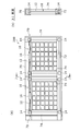
- FIG. 1 is a view showing a packing form 11A of a solar cell module 10 as an example of an embodiment, where (a) is a plan view, (b) is a cross-sectional view taken along line AA in (a), and (c) is a cross-sectional view. It is B arrow view in (a).
- This packing form 11A is configured by stacking solar cell modules 10 in a plurality of stages.
- the solar cell module 10 includes a solar cell panel 12 and a corner block 14.
- the solar cell panel 12 is, for example, a plate-like member that has a square shape in plan view.
- the solar cell panel 12 has a structure in which a plurality of solar cells 2 are sandwiched between, for example, two resin sheets functioning as a sealing material and two protective members such as a glass substrate.
- two resin sheets functioning as a sealing material and two protective members such as a glass substrate.
- an example is shown in which six rows of solar cells 2 arranged in the horizontal direction are arranged in six rows in the vertical direction.
- the corner block 14 is fixed so as to cover the corner of the solar cell panel 12.
- the solar cell panel 12 of the present embodiment has a square shape and has four corners. Therefore, in the solar cell module 10, a total of four corner blocks 14 are fixed to each corner of the solar cell panel 12.
- the solar cell module 10 further includes a terminal box 16 at one edge of the solar cell panel 12.
- the terminal box 16 can be configured by a resin housing, for example.
- the terminal box 16 houses electrical connection terminals for collecting and outputting the electric power generated by the solar cell panel 12.
- the terminal box 16 is attached so as to protrude outward from the edge portion of the solar cell panel 12.
- the terminal box 16 is attached so as to protrude from both side surfaces of the solar cell panel 12 in the plate thickness direction.
- the cable 17 extends from both sides of the terminal box 16, and a connector 18 is connected to the end of the cable 17.
- the cable 17 is a power line for taking out the power generated by the solar battery panel 12.
- the connector 18 is an electrical connection member that is coupled so as to electrically connect the solar cell modules 10 installed adjacent to each other.
- the solar cell panel 12 is in a state where the edge portion is exposed except for the corner portion to which the corner block 14 is fixed and the portion to which the terminal box 16 is attached. Yes. That is, for example, a metal frame is not fixed to the exposed edge of the solar cell panel 12. In this sense, the solar cell panel 12 can be said to be a frameless type solar cell module. However, the solar cell panel 12 has at least an edge portion other than the corner block 14 covered with water, such as a tape, a coating film, a rubber packing that covers the edge portion, a substantially U-shaped metal frame, etc. ) May be provided.
- water such as a tape, a coating film, a rubber packing that covers the edge portion, a substantially U-shaped metal frame, etc.
- each corner block 14 has a protrusion 20 on one surface and a recess 22 on the other surface. Therefore, when the plurality of solar cell modules 10 are stacked in the vertical direction to form the packing form 11A, the concave portion of the solar cell module 10 in which the protrusions 20 of the solar cell module 10 positioned on the lower side are stacked on the upper side. 22 can be stacked by being fitted. Thereby, the several solar cell module 10 can be stacked in the stable state. Moreover, when it is conveyed with this packing form 11A, it is prevented that each solar cell module 10 shifts
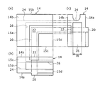
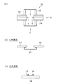
- FIG. 2 is a view showing a corner block 14 as an example of the embodiment, where (a) is a top view, (b) is a front view, and (c) is a side view.
- the corner block 14 is made of, for example, a resin material.
- the corner block 14 may be made of a metal member such as an aluminum die cast product.
- the corner block 14 is integrally formed by one member.
- the corner block 14 is a plate-like member having a substantially square shape in plan view.
- the corner block 14 may be formed in a shape (triangular shape or pentagonal shape in plan view) in which corner portions located on the solar cell panel 12 are cut obliquely.
- the corner block 14 has one side surface 14a and the other side surface 14b facing in the thickness direction of the solar cell panel 12, and four side wall surfaces 15a, 15b, 15c, and 15d that constitute the four sides. These four side wall surfaces 15 a to 15 d are side surfaces along the thickness direction of the solar cell panel 12 when attached to the solar cell panel 12. Of the four side wall surfaces 15a-15d, the side wall surfaces 15a, 15b are side surfaces facing the outside of the solar cell module 10 when attached to the solar cell panel 12.
- the corner block 14 is formed with a cut portion 26 into which a corner portion of the solar cell panel 12 is inserted.
- the cut portion 26 is formed as a concave portion having a shape corresponding to a corner portion of the solar cell panel 12 having a substantially right angle.
- the cut portion 26 is formed in a substantially square shape in plan view.
- the cut portion 26 is opened in the two side wall surfaces 15c and 15d of the corner block 14.
- the width W of the cut portion 26 is set to be slightly larger (for example, about several mm) than the thickness of the solar cell panel 12 in consideration of an arrangement space for an adhesive and the like which will be described later while allowing the solar cell panel 12 to be inserted. ing.
- a protrusion 20 (first protrusion) having an L shape in plan view is formed.
- a concave portion 22 (second concave portion) having an L shape in plan view is formed.
- the recess 22 is formed wider than the protrusion 20.
- the protrusions 20 and the recesses 22 are formed in positions and shapes that fit together when the plurality of solar cell modules 10 are stacked.
- a concave portion (first concave portion) may be formed on the one side surface 14a of the corner block 14, and a protruding portion (second protruding portion) may be formed on the other side surface 14b.
- the shape and number of the protrusions and the recesses are not limited to the L shape or one, and any shape or number can be used as long as the corner block stacking position is defined by the concave / convex fitting. Good.
- the groove 24 for holding the cable 17 and the connector 18 is recessed in one side wall surface 15b facing the outside of the solar cell module 10 when attached to the solar cell panel 12 in the corner block 14.
- the groove 24 has a bottom surface formed as an arcuate curved surface, as shown in FIG.
- the width of the groove 24 is set to such an extent that the cable 17 and the connector 18 can be fitted and held.
- the example in which the cable holding groove 24 is formed on one side wall surface 15b of the corner block 14 has been described.
- the other side wall surface 15a has a cable holding groove.
- the groove may be formed.
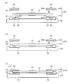
- FIG. 3 (a) to 3 (c) are diagrams showing the state in which the two-segment corner block 14 is attached to the solar cell panel 12 in a stepwise manner.
- the corner block 14 may be configured by combining a lower block 14c and an upper block 14d that are divided into two.
- the two-divided corner block 14 is fixed to the solar cell panel 12 as follows.
- FIG. 3A First, as shown in FIG. 3A, four lower blocks 14c corresponding to the four corners of the solar cell panel 12 are installed on the assembly base 28.
- a shallow concave portion 29 is formed on the upper surface of the assembly base 28 to be positioned by fitting the lower portion of the lower block 14c.
- a double-sided tape 30 is bonded to a surface 26a that forms the cut portion 26 in the lower block 14c.
- a positioning protrusion 32 is formed on the upper surface of the lower block 14c.
- each corner of the solar cell panel 12 is placed on the four lower blocks 14 c installed on the assembly base 28. Thereby, each corner
- the upper block 14d is placed on the lower block 14c.
- a positioning recess 34 is formed on the lower surface of the upper block 14d.
- a silicone-based adhesive 36 is applied in advance to the surface 26b of the upper block 14d forming the cut portion 26.
- the upper block 14d When the upper block 14d is overlaid on the lower block 14c as described above, they are positioned with respect to each other by fitting (protrusion fitting) between the protrusion 32 and the recess 34 as shown in FIG. In this state, the upper block 14d is bonded and fixed to each corner of the surface (or upper surface) of the solar cell panel 12 by the adhesive 36. In this way, the two-divided corner block 14A is fixed to each corner of the solar cell panel 12 by integrating the lower block 14c and the upper block 14d.
- the lower block 14c is quickly fixed to the corner portion of the solar cell panel 12 by the double-sided tape 30, so that the adhesive 36 for fixing the upper block 14d is awaited to be cured.
- the solar cell module 10 can be sent to the next step (for example, packing) without any problems.
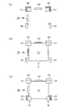
- 4 (a) to 4 (c) are diagrams showing the state in which the integrated corner block 14 shown in FIG.
- first jigs 40 a pair of first jigs 40, a pair of second jigs 42, and first and second positioning walls 44, 46 are installed on the assembly base 38.
- Each first jig 40 has a concave portion 41 having a substantially square shape in plan view in which the corner block 14 is fitted and positioned.
- Each pair of second jigs 42 has an L shape in plan view, and is disposed at a distance corresponding to the length of one side of the solar cell panel 12.
- the first positioning wall 44 is disposed between the pair of first jigs 40.
- the second positioning wall 46 is arranged between one first jig 40 and one second jig 42.
- the corner block 14 is fixed to the solar cell panel 12 as follows using such an assembly table 38.
- a silicone-based adhesive is preferably applied in advance to the inside of the cutout portion 26 of the corner block 14, but instead of or in addition to this, it is bonded to the corner portion of the solar cell panel 12.
- An agent may be applied.
- the two corner blocks 14 are set in the recesses 41 of the pair of first jigs 40, respectively. Then, as shown in FIG. 4B, the two corners of the solar cell panel 12 are inserted in the direction of the arrow K into the notches 26 of the two corner blocks 14 set in the pair of first jigs 40. At this time, the first and second positioning walls 44 and 46 come into contact with two sides orthogonal to each other in the solar cell panel 12. Moreover, at this time, the two opposite side portions of the solar cell panel 12 come into contact with each other while being sandwiched between the pair of second jigs 42. Thereby, the two corner blocks 14 are fixed to the solar cell panel 12 accurately and accurately.
- the corner blocks 14 are inserted from the direction of the arrow M into the remaining two corners of the solar cell panel 12 positioned between the pair of second jigs 42, respectively.
- the fixed position of the corner block 14 with respect to the solar cell panel 12 is accurately determined by contacting the side wall surface of the L-shaped second jig 42. In this way, the four corner blocks 14 are bonded and fixed to the respective corner portions of the solar cell panel 12.
- the corner block 14 (or 14A, the same applies hereinafter) is fixed to each corner of the solar cell panel 12, as shown in FIG.
- the part is covered and protected by the corner block 14. Therefore, it is possible to prevent the glass substrate and the sealing material constituting the corner from being damaged by hitting the corner of the solar cell panel 12 when the solar cell module 10 is transported or installed.
- the corner blocks 14 of the module 10 fit the protrusion 20 and the recessed part 22 directly. Prevents horizontal displacement. Therefore, a plurality of solar cell modules 10 can be stably transported in a stacked state in this state. Moreover, compared with the case where each solar cell module 10 is each packed, the usage-amount of a packing material can be reduced significantly by packing the solar cell module 10 stacked in multiple steps in this way collectively. .
- the corner block 14 has portions protruding on both sides of the solar cell panel 12, so that there is a gap between the solar cell panels 12 included in each solar cell module 10. Is formed.
- This gap is set to a dimension such that the terminal boxes 16 included in each solar cell module 10 do not contact each other. Accordingly, in order to protect the terminal boxes 16 from interfering with each other and being damaged between the plurality of stacked solar cell modules, the periphery of each terminal box 16 is covered with a packing material such as cardboard or between the terminal boxes. There is no need to dispose a spacer member. Therefore, there is an advantage that the labor of packing and the amount of packing material used can be reduced.
- the cable 17 and the connector 18 can be held in the groove 24 formed in the corner block 14. For this reason, when stacking a plurality of solar cell modules 10 or installing them as will be described later, it is possible to prevent the cables 17 and the like from being sandwiched between the solar cell modules 10 and being damaged.
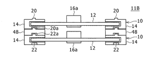
- FIG. 5 is a diagram showing a packing form 11B of the first modified example.
- the packing form 11B is configured by stacking the solar cell modules 10 in a plurality of stages.
- the terminal box 16a of the solar cell module 10 is larger in size than the terminal box 16 described above with reference to FIG. Therefore, the protruding dimension of the terminal box 16a toward the one surface side of the solar cell panel 12 is large.
- the thickness dimension of the spacer member 48 is set in consideration of a gap that does not interfere with the terminal box 16a.
- the spacer member 48 is formed with a recess 22a and a protrusion 20a on the lower surface and the upper surface, respectively, which are fitted into the protrusion 20 and the recess 22 of the corner block 14 positioned vertically.
- the corner blocks 14 positioned above and below are indirectly engaged with each other via the spacer member 48. Thereby, the state which piled up the several solar cell module 10 stably can be maintained.
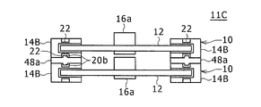
- FIG. 6 is a view showing a packing form 11C of the second modified example.
- This packing form 11C is configured by stacking solar cell modules 10 having corner blocks 14B in a plurality of stages.
- the terminal box 16a of the solar cell module 10 has the same size as that of FIG. Therefore, the spacer member 48a is arranged between the corner blocks 14B of the plurality of stacked solar cell modules 10, and the terminal boxes 16a are stacked so as not to interfere with each other. Further, in this case, positioning concave portions 22 are formed on the upper and lower surfaces of the corner block 14B, and protrusions 20b that fit into the concave portions 22 are formed on the upper and lower surfaces of the spacer member 48a.
- the corner blocks 14B When the positioning concave portions 22 are formed on the upper and lower surfaces of the corner block 14B as described above, it is preferable to stack the corner blocks 14B using the spacer member 48a having the protrusions 20b on the upper and lower surfaces. In this case, the corner blocks 14B positioned above and below are indirectly engaged with each other via the spacer member 48a. Thereby, the terminal boxes 16a do not interfere with each other, and the plurality of solar cell modules 10 can be stably stacked.
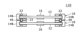
- FIG. 7 is a diagram showing a packing form 11D of the third modified example.
- This packing form 11D is configured by stacking solar cell modules 10 having corner blocks 14B in a plurality of stages.
- positioning concave portions 22 are respectively formed on the upper and lower surfaces of the corner block 14 ⁇ / b> B.
- the terminal box 16 is the same as the solar cell module 10 described above with reference to FIG. 1 and the like, and is a type in which the protruding amount from both surfaces of the solar cell panel 12 is not so large. Therefore, in this case, the terminal boxes 16 do not interfere with each other even if the spacer member is not interposed in the corner block 14B.
- a positioning member 49 that fits into the two concave portions 22 facing each other of the corner blocks 14B stacked vertically is used so that the corner blocks 14B of the stacked solar cell modules 10 are not displaced in the horizontal direction. Is preferred. In this case, the corner blocks B positioned above and below are indirectly engaged with each other via the positioning member 49.
- FIG. 8 is a view showing a packing form 11E of the fourth modified example.
- This packing form 11E is configured by stacking solar cell modules 10 having corner blocks 14C in a plurality of stages.
- the corner block 14C has positioning protrusions 20 on the upper and lower surfaces, respectively.
- spacer members 48b each having a concave portion 22a fitted to the protrusion 20 on the upper and lower surfaces.
- the corner blocks 14C positioned above and below are indirectly engaged with each other via the spacer member 48b.
- the spacer member 48b is also disposed under the corner block 14C of the lowermost solar cell module 10 in order to stably place the lowermost solar cell module 10 on a tray or pallet (not shown). Is preferred.
- FIG. 9 is a diagram showing a support structure 50 of the solar cell module 10 composed of vertical and horizontal ridges formed in a lattice shape.
- 10 (a) is an enlarged view of a part of the support structure 50 shown in FIG. 9
- FIG. 10 (b) is a view taken in the direction of arrow C in FIG. 10 (a)
- FIG. 10 (c) is FIG. It is D arrow line view in (a).
- the support structure 50 includes a plurality of longitudinal ridges 52 (first ridges) arranged in parallel to each other along the first direction, and the first direction.
- the first and second directions can be two directions orthogonal to each other on a horizontal plane.
- the support structure 50 can be used for the horizontal installation type solar power generation device in which the solar cell module 10 is installed along a horizontal plane.
- the support structure may extend along a plane slightly inclined from the horizontal plane.
- the vertical hook 52 is a long member having a substantially C-shaped cross section.
- the longitudinal ridge 52 is made of, for example, C-shaped steel.
- the lateral ridge 54 is a long member having a substantially C-shaped cross section.
- C-shaped steel that is narrower and thinner than the longitudinal ridge 52 can be used as the lateral ridge 54.
- the ends of the horizontal hooks 54 are connected in a state of being placed on the vertical hooks 52.
- a step 53 corresponding to the thickness of the horizontal ridge 54 is formed between the upper surface of the horizontal ridge 54 and the upper surface of the vertical ridge 52.
- the support structure 50 is configured as a rectangular frame having a lattice shape by the vertical ridges 52 and the horizontal ridges 54, and supports the solar battery panel 12 included in the solar power generation device as described later, and rainwater or the like. It functions as a tub that drains water.
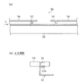
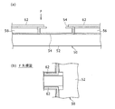
- FIG. 11A is a side view showing a state in which the spacer member 56 is arranged on the vertical flange 52 in the support structure 50 shown in FIG. 9, and FIG. 11B is an E view in FIG. It is an arrow view.
- the support structure 50 further includes a spacer member 56.
- the spacer member 56 has a substantially U-shaped cross section.
- the spacer member 56 is formed to have substantially the same width as the upper overhanging portion 52a of the longitudinal ridge 52, and extends along the upper overhanging portion 52a.
- the spacer member 56 is formed of, for example, a metal material.
- the spacer member 56 is formed to have substantially the same thickness as the lateral ridge 54. Thereby, the level
- FIG. 12 is a view showing a state in which the frameless solar cell panel 13 is installed on the support structure 50 shown in FIG.
- the solar cell panel 13 is hatched for easy understanding.
- the solar cell panel 13 can use the same thing as the solar cell panel 12 of the solar cell module 10 mentioned above.
- the solar cell panel 13 is not provided with a corner block.
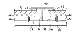
- the fixing member 58 when the solar cell panel 13 is installed using the support structure 50 described above with reference to FIG. 11, the fixing member 58 is erected on the inner bottom surface of the lateral ridge 54 as shown in FIG. 12.
- the lower end portion of the fixing member 58 is fixed to the lateral flange 54 by, for example, welding.
- the upper end portion of the fixing member 58 has a shape bent substantially along the horizontal direction.
- the fixing member 58 is also erected on the inner bottom surface of the vertical hook 52.
- the solar cell panel 13 is arranged in a state where the peripheral edge portion is placed on the lateral ridge 54 and the spacer member 56.
- the fixing plate 60 is fixed to the upper end portion of the fixing member 58 by, for example, screwing over the peripheral edge portions of the two adjacent solar cell panels 13.
- the fixed plate 60 is made of, for example, a metal plate.
- the metal lateral ridge 54 and the spacer member 56 are in direct contact with the back surface of the solar cell panel 13.
- the fixed plate 60 made of a metal plate is in direct contact with the surface of the solar cell panel 13. If it does so, it may happen that protection members, such as a glass substrate which constitutes the front and back of solar cell panel 13, are damaged or cracked.
- FIG. Fig.13 (a) is a figure which shows a mode that the packing member has been arrange
- FIG.3 (b) is F arrow directional view in Fig.13 (a).
- the packing member is shown by dot drawing.
- packing members 62 are disposed on the upper surfaces of the lateral ridge 54 and the spacer member 56.
- the packing member 62 is made of a flexible material such as rubber, for example.
- the packing member 62 is stuck and fixed by the adhesive layer which has on the lower surface, for example.
- FIG. 14 is a view showing a state in which the frameless solar cell panel 13 is installed on the support structure 50 shown in FIG.
- the peripheral part of the solar cell panel 13 is placed on the packing member 62 arranged as described above.
- the fixing plate 60 is attached to the upper end portion of the fixing member 58 erected on the inner bottom surface of the lateral ridge 54.
- a flexible packing member 64 made of, for example, rubber is interposed between the peripheral surface portion of the solar cell panel 13 and the fixing plate 60.
- the peripheral part of the back surface and the front surface of the solar cell panel 13 comes into contact with the lateral ridge 54, the spacer member 56, and the fixing plate 60 through the packing members 62 and 64. Therefore, in this case, a protective member such as a glass substrate constituting the front and back surfaces of the solar cell panel 13 is not damaged.
- the packing members 62 and 64 are deteriorated by long-term use, resulting in water leakage or looseness of the solar cell panel due to loss of flexibility. Is concerned.
- the packing member 62 on the support structure 50 tends to be deteriorated as the weight of the solar cell panel 13 continues to act.
- the above-described leakage or rattling due to deterioration of the packing member is suppressed. can do.
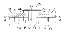
- FIG. 15 is a plan view showing a state in which the solar cell module 10 of the present embodiment shown in FIG. 1 is installed on the support structure 50 shown in FIG.
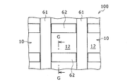
- FIG. 16 is a plan view showing a horizontally installed solar power generation apparatus 100 configured by fixing the solar cell module 10 shown in FIG. 15 to the support structure 50 by a fixing plate 60.
- the solar cell module 10 of the present embodiment is installed on the support structure 50.
- the lower surface of the corner block 14 fixed to the corner portion of the solar cell module 10 is placed on the inner bottom surface 54a of the lateral ridge 54, whereby the solar cell module 10 is supported.
- the fixing plate 60 is attached to the upper end portion of the fixing member 58 erected on the lateral ridge 54.
- the fixing plate 61 is attached to the upper end portion of the fixing member 58 erected on the vertical hook 52.
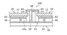
- FIG. 17 is a cross-sectional view taken along the line GG in FIG.
- the lower surface of the corner block 14 of the solar cell module 10 is supported on the inner bottom surface 54 a of the lateral ridge 54.
- a flexible packing member 62 is disposed between the back surface of the solar cell panel 12 and the lateral ridge 54 and the spacer member 56.
- the corner block 14 of the solar cell module 10 is pressed and fixed by the fixing plates 60 and 61 via a flexible packing member 64.
- the packing member may be provided only between the edge of the solar cell panel 12 and the fixing plates 60 and 61 at a position other than the corner block 14.
- the weight of the solar cell module 10 is supported by the support structure 50 including the lateral ridge 54. Therefore, since the weight of the solar cell module 10 does not act on the packing member 62 disposed in contact with the back surface of the solar cell panel 12, it is possible to suppress the occurrence of water leakage and rattling due to deterioration of the packing member 62.
- FIG. 18 is a view corresponding to FIG. 17, showing an example in which the height adjusting member 19 is connected to the lower surface of the corner block 14.
- a height adjusting member 19 may be connected to the lower surface of the corner block 14.
- the height adjusting member 19 is fixed by bonding, screwing, or the like in a state where the height adjusting member 19 is positioned with respect to the corner block 14 by uneven fitting.
- corner block 14 is mounted and supported on the inner bottom face 54a of the horizontal direction cage
- the corner block 14 may be placed on the inner bottom surface of the vertical ridge 52 to support the solar cell module 10.
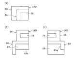
- FIG. 19A is a top view
- FIG. 19B is a front view
- FIG. 19C is a side view showing a corner block 14D of a third modification.
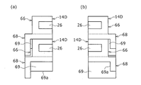
- 20A is a front view
- FIG. 20B is a side view showing a state in which the corner blocks 14D shown in FIG. 19 are stacked.
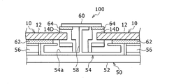
- FIG. 21 is a view corresponding to FIG. 17, showing a state in which the solar cell module 10 having the corner block 14 ⁇ / b> D shown in FIG. 19 is installed on the support structure 50 shown in FIG. 13.
- the corner block 14D has an upper portion 66 and a lower portion 68 in the vertical direction in the installed state of the solar power generation device 100.
- the upper portion 66 is formed in a rectangular parallelepiped shape in substantially the same manner as the corner block 14 in the above-described embodiment, and is formed with a cut portion 26 that opens in two side wall surfaces.
- the cut portion 26 is a concave portion in which a corner portion of the solar cell panel 12 is inserted and fixed.
- the lower portion 68 of the corner block 14D is a portion that rests on the inner bottom surface 54a of the lateral ridge 54, and is a plate whose thickness along the width direction of the lateral ridge 54 is thinner than the length along the longitudinal direction of the lateral ridge 54. It is formed in a shape. Since the lower portion 68 of the corner block 14D is formed in a plate shape in this way, it is formed inside the lateral ridge 54 when placed on the inner bottom surface 54a of the lateral ridge 54 as shown in FIG. The reduction of the flow path area can be suppressed, and a smooth water flow can be secured.
- the plate-like lower portion 68 is formed to protrude outward from the side surface of the substantially rectangular parallelepiped upper portion 66, and an accommodating portion 69 for accommodating the upper portion of another corner block 14D is formed inside thereof.
- the plurality of corner blocks 14 ⁇ / b> D can be arranged in an orderly and compact manner in a state where the upper portion 66 of another corner block 14 ⁇ / b> D is accommodated in the accommodation portion 69.
- the upper part 66 accommodated in the accommodating part 69 is positioned in contact with the side wall 69 a included in the lower part 68.
- FIGS. 22A and 22B are views showing a state where the vertically installed solar power generation apparatus 200 is installed.
- FIG. 22A is a front view
- FIG. 22B is a cross-sectional view taken along line HH in FIG.
- FIGS. 23A and 23B are diagrams showing the installation completion state of the photovoltaic power generation apparatus 200 shown in FIG. 22, wherein FIG. 23A is a front view, and FIG. 23B is a JJ cross-sectional view in FIG.
- the solar power generation device 200 includes a vertically installed rectangular frame 70 and a solar cell module 10.
- the solar cell module 10 is the same as that described with reference to FIG. 1 and the like, and the description thereof is omitted here using the same reference numerals.
- the rectangular frame 70 includes a lower frame 72 having a substantially U-shaped cross section, two vertical frames 74 having a substantially U-shaped cross section standing on both ends of the lower frame 72, and upper ends of the two vertical frames 74, respectively. And an upper cover 76 attached in parallel with the lower frame. 22 and 23 show an example in which two rectangular frames 70 are connected side by side with the lower frame 72 in common.
- the lower frame 72 and the vertical frame 74 are each formed of U-shaped steel, for example, and are connected to each other by welding or the like.
- the upper cover 76 is formed of U-shaped steel, for example.
- the solar cell module 10 is inserted between the two vertical frames 74 in the arrow direction from above and installed.
- the corner block 14 of the solar cell module 10 is inserted in contact with the opposing side wall surfaces of the vertical frame 74. Therefore, the solar cell panel 12 does not contact the vertical frame 74, and the solar cell panel 12 can be prevented from being damaged during installation.
- the corner block 14 fixed to the corner portion of the solar cell panel 13 contacts the inner bottom surface of the lower frame 72. In this state, the lower edge portion of the solar cell panel 12 is positioned away from the inner bottom surface when the corner block 14 contacts the inner bottom surface of the lower frame 72. Therefore, it is possible to effectively suppress the corners and lower edge of the solar cell panel 12 from colliding with the inner bottom surface of the lower frame 72 and being damaged.
- the solar cell module 10 is installed inside the lower frame 72 and the vertical frame 74 as described above.
- the cable 17 may be fitted into a groove 24 (see FIG. 2) recessed in the corner block 14.
- the upper cover 76 is placed over the upper ends of the four vertical frames 74 and fixed by, for example, screwing or the like.
- the upper cover 76 is also formed as a member common to the two rectangular frames 70.
- the installation of the vertically installed solar power generation apparatus 200 is completed.
- FIG. 24 is an enlarged view showing the inside of the lower frame 72 in the photovoltaic power generation apparatus 200 shown in FIG. 23, (a) shows the case of the solar cell module 10 of the present embodiment, and (b) a corner block is provided. The case of the solar cell panel which is not done is shown.
- the solar cell panel 12 is fixed by the corner block 14 fixed to the corner of the solar cell panel 12. Is held at a position away from the inner bottom surface 73. Therefore, even when the water 79 accumulates in the lower frame 72, the lower edge portion of the solar cell panel 13 is less likely to be immersed in the water 79, and the possibility of being immersed in the solar cell panel 12 can be reduced.
- a corner block is included in a solar cell module including a rectangular solar cell panel. May be applied.
- each has two short sides and a long side connecting the four corners, but in addition to fixing the corner block to the four corners, the middle of the long side It is preferable that the intermediate support block is fixed at a position so that the central region of the solar cell panel is not bent downward.
- FIGS. 25 (a) to 25 (c) illustrate.
- one or a plurality of edge blocks 14e may be fixed to a straight side portion of the edge portion of the solar cell panel 12 so as to cover a part of the side portion.
- the solar cell module 10 which is one aspect of the embodiment includes a solar cell panel 12 having a corner portion in plan view, and a plurality of corner blocks 14 that are fixed to cover each corner portion of the solar cell panel 12. . According to this structure, it can prevent that the corner
- the corner block 14 has a cut portion 26 into which the corner portion of the solar cell panel 12 is inserted into the side surfaces 15c and 15d along the thickness direction of the solar cell panel 12. It is suitable to have. Thereby, in the state which inserted the corner
- the corner block 14 has one side surface 14a and the other side surface 14b facing the thickness direction of the solar cell panel 12, and the one side surface 14a has a first surface 14a. Even if the 1 protrusion 20 or the 1st recessed part is formed and the 2nd protrusion 22 which can be fitted to the 1st recessed part is formed in the other side surface 14b, the 2nd recessed part 22 which can be fitted in the 1st recessed part is formed. Good. If comprised in this way, it can be piled up stably in multiple steps
- the groove 24 into which the cable 17 for taking out the electric power generated by the solar cell panel 12 is fitted in the side surface 15b of the corner block 14 facing the outside of the solar cell module. May be recessed. If comprised in this way, the cable 17 is inserted between the solar cell module 10 and the support structure 50 at the time of installation of the solar cell module 10 etc. by fitting the cable 17 (and the connector 18 at the cable end) with the corner block. It will not be damaged by pinching.
- the corner block 14A includes an upper block 14d that is bonded to the surface of the solar cell panel 12, and a lower block 14c that is bonded to the back surface of the solar cell panel 12. It may be constituted by. If comprised in this way, the lower block 14c will be positioned and mounted in the assembly stand 28, and the corner
- the back surface of the solar cell panel 12 is bonded to the lower block 14c by the double-sided tape 30, and the surface of the solar cell panel 12 is bonded to the upper block 14d by an adhesive. If comprised in this way, since the lower block 14c is rapidly fixed to the corner
- the module 10 can be sent to the next step (eg, packing, etc.).
- the upper block 14d and the lower block 14c may be bonded to the solar cell panel in a state where they are positioned with respect to each other by the concave and convex fitting portions. If comprised in this way, corner block 14A will be fixed in the state where the upper block 14c and the lower block 14d were correctly positioned with respect to the corner
- Another aspect of the embodiment includes a solar cell panel 12 having a corner shape in a plan view, and a plurality of corner blocks 14 and 14A-C that cover and fix each corner portion of the solar cell panel 12, respectively.
- the solar cell panel packaging form 11A-11E is configured by stacking the solar cell modules 10 provided in a plurality of stages, and the plurality of solar cell modules 10 are provided with corner blocks 14 and 14A-C positioned on the upper and lower sides. By stacking in a combined state, the solar cell panels 12 are stacked so that a gap is formed.
- a plurality of solar cell modules can be packed in a state where they are stably stacked in a plurality of stages. Further, since the gap is formed between the solar cell panels, the terminal boxes 16 fixed to the solar cell panels 12 can be packed without interfering with each other.
- corner blocks 14 and 14A-C positioned on the upper and lower sides may be directly concavo-convexly fitted, or may be concavo-convexly fitted via the spacer member 48 or the positioning member 49. If comprised in this way, the clearance gap between the solar cell panels 12 can be changed according to the size of the terminal box 16.
- the photovoltaic power generation apparatus 100 which is still another aspect of the embodiment includes a plurality of first rods 52 arranged in parallel to each other along the first direction and a direction orthogonal to the first direction.
- a support structure 50 including a plurality of second rods 54 arranged in parallel to each other and having both ends connected to the first rods 52, and a rectangular frame constituted by the first rods 52 and the second rods 54.
- a solar cell module of the above-described actual form installed on top. The solar cell module 12 is supported by placing the lower surface of the corner block 14 on the inner bottom surface 54a of the second rod 54.
- the solar power generation device 100 includes a fixing member 58 erected on the first rod 52, and a fixing plate that is connected to the fixing member 58 and is fixed to the support structure 50 by pressing the edge of the solar cell module. 60 may be further provided.
- a step 53 is formed between the first rod 52 and the second rod 54, and a spacer member 56 that fills the step 53 is disposed.
- the solar cell panel 12 is disposed through a flexible packing member 62 provided in the housing. If comprised in this way, the weight of the solar cell module 100 will be supported by the corner block 14 in which the lower surface was mounted in the inner bottom face 54a of the 2nd collar 54. Therefore, the flexible packing member 62 can be prevented from being deteriorated in a compressed state by receiving a load from the solar cell module 10, and as a result, the solar cell panel 12 can be prevented from rattling and the packing member 62 can be prevented from being flooded. Can be maintained.
- the installation height of the solar cell module 10 with respect to the support structure 50 may be adjusted by the height adjustment member 19 connected to the lower surface of the corner block 14. . If comprised in this way, the installation height of the solar cell panel 12 with respect to the support structure 50 can be adjusted easily.
- the lower portion of the corner block 14 placed on the inner bottom surface 54a of the second rod 54 has a thickness along the width direction of the first rod 54. It may be formed in a plate shape thinner than the length along the longitudinal direction. If comprised in this way, the reduction
- the photovoltaic power generation apparatus 200 which is still another aspect of the embodiment includes a lower frame 72 having a substantially U-shaped cross section, and two vertical frames 74 having a substantially U-shaped cross section which are respectively provided on both ends of the lower frame 72. And a vertically installed rectangular frame 70 including an upper cover 76 attached in parallel to the lower frame 72 over the upper ends of the two vertical frames 74, and the above-mentioned installed in a state where the periphery is supported by the rectangular frame 70
- the solar cell module 10 which is one aspect
- the lower part of the solar cell panel 12 constituting the solar cell module 10 is positioned away from the inner bottom surface 73 when the corner block 14 contacts the inner bottom surface 73 of the lower frame 72. To do. If comprised in this way, even when water accumulates in the inner bottom face 73 of the lower frame 72, it can avoid that the lower edge part of the solar cell panel 12 will be in the state immersed in water, and water penetrate
- the cable 17 connected to the terminal box 16 of the solar cell module 10 may be fitted into a groove 24 that is recessed in the side surface of the corner block 14. If comprised in this way, it can prevent that the part which attached the cable 17 to the terminal box 16 continues a stress, and is inserted
Landscapes
- Engineering & Computer Science (AREA)
- Architecture (AREA)
- Civil Engineering (AREA)
- Structural Engineering (AREA)
- Mechanical Engineering (AREA)
- Photovoltaic Devices (AREA)
- Packaging Frangible Articles (AREA)
Abstract
La présente invention empêche un endommagement de parties d'angle d'un panneau solaire photovoltaïque pendant le transport et l'installation d'un module de cellule solaire en raison du fait que les parties d'angle du panneau solaire photovoltaïque sont recouvertes et que les blocs d'angle sont fixés. Le module de cellule solaire 10 est pourvu : d'un panneau solaire photovoltaïque 12 formant une forme ayant des parties d'angle dans une vue en plan ; et d'une pluralité de blocs d'angle 14 recouvrant les parties d'angle du panneau solaire photovoltaïque 12, chaque bloc de la pluralité de blocs d'angle 14 étant fixé.
Priority Applications (2)
| Application Number | Priority Date | Filing Date | Title |
|---|---|---|---|
| CN201780053268.3A CN109804555A (zh) | 2016-09-02 | 2017-08-23 | 太阳能电池组件、其捆包方式和太阳能发电装置 |
| JP2018537176A JP6830264B2 (ja) | 2016-09-02 | 2017-08-23 | 太陽電池モジュール、その梱包形態、及び、太陽光発電装置 |
Applications Claiming Priority (2)
| Application Number | Priority Date | Filing Date | Title |
|---|---|---|---|
| JP2016171681 | 2016-09-02 | ||
| JP2016-171681 | 2016-09-02 |
Publications (1)
| Publication Number | Publication Date |
|---|---|
| WO2018043233A1 true WO2018043233A1 (fr) | 2018-03-08 |
Family
ID=61300755
Family Applications (1)
| Application Number | Title | Priority Date | Filing Date |
|---|---|---|---|
| PCT/JP2017/030056 Ceased WO2018043233A1 (fr) | 2016-09-02 | 2017-08-23 | Module de cellule solaire, son mode d'encapsulation, et dispositif de production d'énergie solaire |
Country Status (3)
| Country | Link |
|---|---|
| JP (1) | JP6830264B2 (fr) |
| CN (1) | CN109804555A (fr) |
| WO (1) | WO2018043233A1 (fr) |
Cited By (3)
| Publication number | Priority date | Publication date | Assignee | Title |
|---|---|---|---|---|
| KR20210073816A (ko) * | 2019-12-11 | 2021-06-21 | 재단법인 구미전자정보기술원 | 블록형 태양전지 모듈 |
| CN116505857A (zh) * | 2023-04-12 | 2023-07-28 | 滁州瑞达新能源材料有限公司 | 一种便于拼装的太阳能板铝型材边框 |
| CN117988469A (zh) * | 2024-03-21 | 2024-05-07 | 中建深圳装饰有限公司 | 一种泡沫混凝土保温板 |
Citations (7)
| Publication number | Priority date | Publication date | Assignee | Title |
|---|---|---|---|---|
| US20020056656A1 (en) * | 2000-11-10 | 2002-05-16 | Jean-Louis Beliveau | Extensible packing protector |
| JP2003243685A (ja) * | 2002-02-14 | 2003-08-29 | Sekisui Jushi Co Ltd | 太陽電池パネルの製造方法、太陽電池パネル及びその太陽電池パネルを用いた防音壁 |
| JP2004335903A (ja) * | 2003-05-12 | 2004-11-25 | Hitachi Ltd | 両面受光型太陽電池アレイ |
| JP2009246018A (ja) * | 2008-03-28 | 2009-10-22 | Kyocera Corp | 太陽電池モジュール |
| JP2012190844A (ja) * | 2011-03-08 | 2012-10-04 | Sharp Corp | 太陽電池モジュールの多段積載方法 |
| JP2015056569A (ja) * | 2013-09-13 | 2015-03-23 | シャープ株式会社 | 太陽電池モジュール |
| JP2016011517A (ja) * | 2014-06-27 | 2016-01-21 | 株式会社Lixil | 太陽光パネル架台 |
Family Cites Families (3)
| Publication number | Priority date | Publication date | Assignee | Title |
|---|---|---|---|---|
| EP1617485B1 (fr) * | 2004-07-12 | 2007-06-06 | Häberlein-Lehr, Ulla | Système modulaire d'assemblage pour le stockage sûr de modules photovoltaiques empilés horizontalement pendant le transport |
| JP5060363B2 (ja) * | 2008-03-28 | 2012-10-31 | 京セラ株式会社 | フレームレス太陽電池モジュールの保護部材 |
| WO2012030762A2 (fr) * | 2010-08-30 | 2012-03-08 | First Solar, Inc | Elément de protection de module solaire |
-
2017
- 2017-08-23 WO PCT/JP2017/030056 patent/WO2018043233A1/fr not_active Ceased
- 2017-08-23 JP JP2018537176A patent/JP6830264B2/ja not_active Expired - Fee Related
- 2017-08-23 CN CN201780053268.3A patent/CN109804555A/zh active Pending
Patent Citations (7)
| Publication number | Priority date | Publication date | Assignee | Title |
|---|---|---|---|---|
| US20020056656A1 (en) * | 2000-11-10 | 2002-05-16 | Jean-Louis Beliveau | Extensible packing protector |
| JP2003243685A (ja) * | 2002-02-14 | 2003-08-29 | Sekisui Jushi Co Ltd | 太陽電池パネルの製造方法、太陽電池パネル及びその太陽電池パネルを用いた防音壁 |
| JP2004335903A (ja) * | 2003-05-12 | 2004-11-25 | Hitachi Ltd | 両面受光型太陽電池アレイ |
| JP2009246018A (ja) * | 2008-03-28 | 2009-10-22 | Kyocera Corp | 太陽電池モジュール |
| JP2012190844A (ja) * | 2011-03-08 | 2012-10-04 | Sharp Corp | 太陽電池モジュールの多段積載方法 |
| JP2015056569A (ja) * | 2013-09-13 | 2015-03-23 | シャープ株式会社 | 太陽電池モジュール |
| JP2016011517A (ja) * | 2014-06-27 | 2016-01-21 | 株式会社Lixil | 太陽光パネル架台 |
Cited By (4)
| Publication number | Priority date | Publication date | Assignee | Title |
|---|---|---|---|---|
| KR20210073816A (ko) * | 2019-12-11 | 2021-06-21 | 재단법인 구미전자정보기술원 | 블록형 태양전지 모듈 |
| KR102280813B1 (ko) | 2019-12-11 | 2021-07-23 | (재)구미전자정보기술원 | 블록형 태양전지 모듈 |
| CN116505857A (zh) * | 2023-04-12 | 2023-07-28 | 滁州瑞达新能源材料有限公司 | 一种便于拼装的太阳能板铝型材边框 |
| CN117988469A (zh) * | 2024-03-21 | 2024-05-07 | 中建深圳装饰有限公司 | 一种泡沫混凝土保温板 |
Also Published As
| Publication number | Publication date |
|---|---|
| JP6830264B2 (ja) | 2021-02-17 |
| JPWO2018043233A1 (ja) | 2019-07-11 |
| CN109804555A (zh) | 2019-05-24 |
Similar Documents
| Publication | Publication Date | Title |
|---|---|---|
| US11522089B2 (en) | Double-glass photovoltaic assembly | |
| EP3252848B1 (fr) | Dispositif cellulaire, unité cellulaire, et procédé d'installation de dispositif cellulaire | |
| JP6134157B2 (ja) | 電池パック | |
| KR101592663B1 (ko) | 연료전지용 스택 | |
| CN104125920A (zh) | 支承构造体、装载捆包装置、支承基板及捆包方法 | |
| KR102223809B1 (ko) | 2차 전지 셀 모듈 및 그 조립 방법 | |
| KR102131613B1 (ko) | 배터리케이스 및 이의 제작 방법 | |
| CN101675529A (zh) | 太阳能电池模块装置 | |
| US12176557B2 (en) | Battery module and battery pack including the same | |
| EP2811535B1 (fr) | Module de cellule solaire | |
| US20200203697A1 (en) | Battery Module and Battery Module Assembly | |
| US20190305268A1 (en) | Battery module including strap-type frame, and frame assembly therefor | |
| JP6830264B2 (ja) | 太陽電池モジュール、その梱包形態、及び、太陽光発電装置 | |
| CN113728500B (zh) | 电池组 | |
| US20110155220A1 (en) | Solar panel tile structure and combination thereof | |
| JP2012229021A (ja) | フレームなし太陽光発電パネル用保護モジュール | |
| CN108713263A (zh) | 包括用于防止电池组盖回弹的托盘止动器的电池组 | |
| US9906186B2 (en) | Holding frame and solar cell module | |
| KR102768067B1 (ko) | 휴대폰 배터리 장착시스템 | |
| JP7020867B2 (ja) | 電池ケース | |
| CN218868176U (zh) | 用于光伏组件的边框及光伏组件 | |
| JP2025531557A (ja) | 電池モジュールおよびこれを含む電池パック | |
| JP6363395B2 (ja) | 太陽電池モジュールの梱包材 | |
| JP2016197939A (ja) | 端子ボックス | |
| JP2006165017A (ja) | 太陽電池モジュール用端子ボックス |
Legal Events
| Date | Code | Title | Description |
|---|---|---|---|
| 121 | Ep: the epo has been informed by wipo that ep was designated in this application |
Ref document number: 17846238 Country of ref document: EP Kind code of ref document: A1 |
|
| ENP | Entry into the national phase |
Ref document number: 2018537176 Country of ref document: JP Kind code of ref document: A |
|
| NENP | Non-entry into the national phase |
Ref country code: DE |
|
| 122 | Ep: pct application non-entry in european phase |
Ref document number: 17846238 Country of ref document: EP Kind code of ref document: A1 |