WO2018043256A1 - Dispositif de codage d'image, et dispositif de décodage d'image - Google Patents
Dispositif de codage d'image, et dispositif de décodage d'image Download PDFInfo
- Publication number
- WO2018043256A1 WO2018043256A1 PCT/JP2017/030179 JP2017030179W WO2018043256A1 WO 2018043256 A1 WO2018043256 A1 WO 2018043256A1 JP 2017030179 W JP2017030179 W JP 2017030179W WO 2018043256 A1 WO2018043256 A1 WO 2018043256A1
- Authority
- WO
- WIPO (PCT)
- Prior art keywords
- sub
- coding unit
- prediction
- image
- pixel
- Prior art date
- Legal status (The legal status is an assumption and is not a legal conclusion. Google has not performed a legal analysis and makes no representation as to the accuracy of the status listed.)
- Ceased
Links
Images









Classifications
-
- H—ELECTRICITY
- H04—ELECTRIC COMMUNICATION TECHNIQUE
- H04N—PICTORIAL COMMUNICATION, e.g. TELEVISION
- H04N19/00—Methods or arrangements for coding, decoding, compressing or decompressing digital video signals
- H04N19/10—Methods or arrangements for coding, decoding, compressing or decompressing digital video signals using adaptive coding
- H04N19/102—Methods or arrangements for coding, decoding, compressing or decompressing digital video signals using adaptive coding characterised by the element, parameter or selection affected or controlled by the adaptive coding
- H04N19/119—Adaptive subdivision aspects, e.g. subdivision of a picture into rectangular or non-rectangular coding blocks
-
- H—ELECTRICITY
- H04—ELECTRIC COMMUNICATION TECHNIQUE
- H04N—PICTORIAL COMMUNICATION, e.g. TELEVISION
- H04N19/00—Methods or arrangements for coding, decoding, compressing or decompressing digital video signals
- H04N19/50—Methods or arrangements for coding, decoding, compressing or decompressing digital video signals using predictive coding
- H04N19/593—Methods or arrangements for coding, decoding, compressing or decompressing digital video signals using predictive coding involving spatial prediction techniques
-
- H—ELECTRICITY
- H04—ELECTRIC COMMUNICATION TECHNIQUE
- H04N—PICTORIAL COMMUNICATION, e.g. TELEVISION
- H04N19/00—Methods or arrangements for coding, decoding, compressing or decompressing digital video signals
- H04N19/10—Methods or arrangements for coding, decoding, compressing or decompressing digital video signals using adaptive coding
- H04N19/102—Methods or arrangements for coding, decoding, compressing or decompressing digital video signals using adaptive coding characterised by the element, parameter or selection affected or controlled by the adaptive coding
- H04N19/103—Selection of coding mode or of prediction mode
- H04N19/105—Selection of the reference unit for prediction within a chosen coding or prediction mode, e.g. adaptive choice of position and number of pixels used for prediction
-
- H—ELECTRICITY
- H04—ELECTRIC COMMUNICATION TECHNIQUE
- H04N—PICTORIAL COMMUNICATION, e.g. TELEVISION
- H04N19/00—Methods or arrangements for coding, decoding, compressing or decompressing digital video signals
- H04N19/10—Methods or arrangements for coding, decoding, compressing or decompressing digital video signals using adaptive coding
- H04N19/134—Methods or arrangements for coding, decoding, compressing or decompressing digital video signals using adaptive coding characterised by the element, parameter or criterion affecting or controlling the adaptive coding
- H04N19/136—Incoming video signal characteristics or properties
- H04N19/14—Coding unit complexity, e.g. amount of activity or edge presence estimation
-
- H—ELECTRICITY
- H04—ELECTRIC COMMUNICATION TECHNIQUE
- H04N—PICTORIAL COMMUNICATION, e.g. TELEVISION
- H04N19/00—Methods or arrangements for coding, decoding, compressing or decompressing digital video signals
- H04N19/10—Methods or arrangements for coding, decoding, compressing or decompressing digital video signals using adaptive coding
- H04N19/169—Methods or arrangements for coding, decoding, compressing or decompressing digital video signals using adaptive coding characterised by the coding unit, i.e. the structural portion or semantic portion of the video signal being the object or the subject of the adaptive coding
- H04N19/17—Methods or arrangements for coding, decoding, compressing or decompressing digital video signals using adaptive coding characterised by the coding unit, i.e. the structural portion or semantic portion of the video signal being the object or the subject of the adaptive coding the unit being an image region, e.g. an object
- H04N19/176—Methods or arrangements for coding, decoding, compressing or decompressing digital video signals using adaptive coding characterised by the coding unit, i.e. the structural portion or semantic portion of the video signal being the object or the subject of the adaptive coding the unit being an image region, e.g. an object the region being a block, e.g. a macroblock
-
- H—ELECTRICITY
- H04—ELECTRIC COMMUNICATION TECHNIQUE
- H04N—PICTORIAL COMMUNICATION, e.g. TELEVISION
- H04N19/00—Methods or arrangements for coding, decoding, compressing or decompressing digital video signals
- H04N19/70—Methods or arrangements for coding, decoding, compressing or decompressing digital video signals characterised by syntax aspects related to video coding, e.g. related to compression standards
Definitions
- H. Video coding standards such as H.264 / AVC and HEVC (High Efficiency Video Coding) use a prediction technique called intra prediction.
- Intra prediction improves coding efficiency by reducing the spatial redundancy of the image.
- pixels in a prediction target block are predicted based on a reference image including encoded / decoded pixels adjacent to the left end or upper end of the prediction target block.
- coding is performed in units of 2N ⁇ 2N pixel square blocks (CTU (Coding Tree Unit)) obtained by dividing a picture.
- CTU Coding Tree Unit
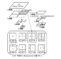
- FIG. 2 the CTU can be recursively divided into quadtrees, and a block after the division is called a CU (Coding Unit: coding unit).
- CU Coding Unit: coding unit
- JEM Joint Exploration Test Model
- binary tree division can be selected in addition to quadtree division.
- PU Prediction Unit
- PU can be basically identified with CU with respect to intra prediction.
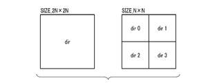
- the CU size is the smallest (N ⁇ N pixels), as shown in the right of FIG. 3, it is divided into four PUs only for the luminance CB (Coding Block) constituting the CU. Can do.
- the maximum CTU size (that is, the maximum PU size) is 64 ⁇ 64 pixels. In view of the recent increase in video resolution, this maximum size is expected to be even larger in future video coding standards. Actually, the maximum size of CTU in JEM is expanded to 256 ⁇ 256 pixels. The extension of the maximum size of the CTU also means the extension of the maximum size of the PU. If the size of the PU is increased, the distance between the lower and right pixels of the PU and the reference image is increased, so that the difference value between these pixels and the reference image is increased, and the prediction efficiency may be reduced. .
- the present invention aims to improve the coding efficiency of intra prediction.
- an image encoding device includes a divider, a determiner, an intra predictor, a subtractor, and an encoder.
- the divider divides the coding unit into a plurality of subcoding units.
- the determiner determines a prediction mode of each of the plurality of subcoding units.
- the intra predictor includes a plurality of pixels adjacent to the left end of the coding unit and a plurality of pixels adjacent to the top end of the coding unit when sub-coding unit division is applied to divide the coding unit into a plurality of sub-coding units.
- intra prediction according to the prediction mode is performed on each of the plurality of subcoding units to generate an intra prediction image of the coding unit.
- the subtracter subtracts the intra prediction image from the coding unit to generate a prediction difference.
- the encoder encodes a quantized transform coefficient generated based on the prediction difference and information indicating application / non-application of subcoding unit division, and information indicating the prediction mode when subcoding unit division is applied. Further encoding is performed.
- the encoding efficiency of intra prediction can be improved.
- FIG. 1 is a block diagram illustrating an image encoding device according to a first embodiment.
- Explanatory drawing of the block structure in HEVC Explanatory drawing of PU division
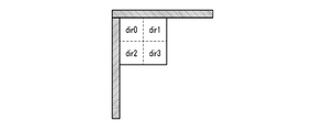
- FIG. 11 is an explanatory diagram of a reference image that is commonly used for intra prediction on four Sub-CUs obtained by dividing the CU of FIG. 10 into a quadtree.
- FIG. 11 is an explanatory diagram of a reference image commonly used for intra prediction for two Sub-CUs obtained by dividing the CU of FIG. 10 into a binary tree (left and right).
- FIG. 11 is an explanatory diagram of a reference image commonly used for intra prediction for two Sub-CUs obtained by dividing the CU of FIG.
- FIG. 10 is into a binary tree (upper and lower).
- FIG. 3 is an explanatory diagram of DC prediction performed by the intra predictor in FIG. 1 in consideration of pixel positions.
- Explanatory drawing of Vertical prediction which considered the pixel position performed by the intra predictor of FIG.
- FIG. 3 is an explanatory diagram of Horizontal prediction in consideration of pixel positions performed by the intra predictor of FIG. 1.
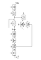
- 3 is a flowchart illustrating an operation related to intra prediction of the image encoding device in FIG. 1.
- the block diagram which illustrates the picture decoding device concerning a 2nd embodiment.
- the image encoding apparatus includes an A / D (Analog / Digital) converter 101, a reorder buffer 102, a subtractor 103, and an orthogonal transformer 104. , Quantizer 105, inverse quantizer 106, inverse orthogonal transformer 107, adder 108, loop filter 109, frame memory 110, motion predictor 111, intra predictor 112, Sub A CU divider 113, a Sub-CU prediction mode determiner 114, an entropy encoder 115, and an HRD (Hypothetical Reference Decoder) buffer 116;
- a / D Analog / Digital
- the A / D converter 101 receives an input signal from a preceding device (not shown) such as a video camera. This input signal may be, for example, an analog video signal (luminance signal and color difference signal). The A / D converter 101 performs analog / digital conversion on the video signal to generate a digital video signal. The A / D converter 101 outputs a digital video signal to the reorder buffer 102.
- a preceding device not shown
- This input signal may be, for example, an analog video signal (luminance signal and color difference signal).
- the A / D converter 101 performs analog / digital conversion on the video signal to generate a digital video signal.
- the A / D converter 101 outputs a digital video signal to the reorder buffer 102.
- the subtractor 103 receives the video signal from the reorder buffer 102 and receives a predicted image (signal) (that is, an inter predicted image (signal) or an intra predicted image (signal) from either the motion predictor 111 or the intra predictor 112. ).
- the subtracter 103 subtracts the predicted image from the video signal to obtain a prediction difference (signal).
- the subtractor 103 outputs the prediction difference to the orthogonal transformer 104.
- Orthogonal transformer 104 applies orthogonal transformation to the prediction difference to generate a transform coefficient.
- This orthogonal transform may be, for example, integer precision DCT (Discrete Cosine Transform), integer precision DST (Discrete Sine Transform), or the like.
- the orthogonal transformer 104 performs orthogonal transformation in units of TU (Transform Unit) such as 4 ⁇ 4 pixels, 8 ⁇ 8 pixels, 16 ⁇ 16 pixels, and 32 ⁇ 32 pixels, for example. Note that the orthogonal transformer 104 can also select conversion skip (that is, pass-through).
- the orthogonal transformer 104 outputs the transform coefficient to the quantizer 105.
- the quantizer 105 receives the transform coefficient from the orthogonal transformer 104.
- the quantizer 105 quantizes the transform coefficient using a quantization parameter determined by a coding controller (not shown) to obtain a quantized transform coefficient.
- the quantizer 105 performs quantization in units of TUs.
- the quantizer 105 outputs the quantized transform coefficient to the inverse quantizer 106 and the entropy encoder 115.
- the inverse quantizer 106 receives the quantized transform coefficient from the quantizer 105.
- the inverse quantizer 106 inversely quantizes the quantized transform coefficient using the above-described quantization parameter, and restores the transform coefficient.
- the inverse quantizer 106 outputs the transform coefficient to the inverse orthogonal transformer 107.
- the inverse orthogonal transformer 107 receives the transform coefficient from the inverse quantizer 106.
- the inverse orthogonal transformer 107 applies inverse orthogonal transform to the transform coefficient to restore the prediction difference.
- This inverse orthogonal transform corresponds to the inverse transform of the orthogonal transform applied by the orthogonal transformer 104.
- the inverse orthogonal transform may be, for example, integer precision IDCT (Inverse DCT), integer precision IDST (Inverse DST), or the like. Note that the inverse orthogonal transformer 107 selects the conversion skip in the same manner when the conversion skip is selected by the orthogonal transformer 104.
- the inverse orthogonal transformer 107 outputs the prediction difference to the adder 108.
- the adder 108 receives the prediction difference from the inverse orthogonal transformer 107 and receives the prediction image from either the motion predictor 111 or the intra predictor 112. The adder 108 adds the prediction difference to the predicted image to generate a (local) decoded image (signal). The adder 108 outputs the decoded image to the loop filter 109 or the frame memory 110. That is, the loop filter 109 can be turned on / off.
- the loop filter 109 receives the decoded image from the adder 108.
- the loop filter 109 applies loop filter processing to the decoded image.
- the loop filter process may be a deblocking filter process, a pixel adaptive offset (SAO) process, or the like. Note that the deblocking filter processing is applied to the boundary pixels of the PU or TU, and reduces the subjective distortion of the block boundary. Pixel adaptive offset processing reduces ringing distortion within the block.
- the loop filter 109 outputs the filtered decoded image to the frame memory 110.
- the frame memory 110 is, for example, a semiconductor memory.
- the frame memory 110 receives the decoded image from either the adder 108 or the loop filter 109.
- the frame memory 110 stores the decoded image as a reference image (signal) candidate.
- the frame memory 110 is also called a decoded picture buffer.
- the decoded image stored in the frame memory 110 is read as a reference image as necessary by the motion predictor 111 or the intra predictor 112.
- the motion predictor 111 receives a video signal from the reorder buffer 102, performs interframe motion compensation prediction (also referred to as inter prediction), and generates an inter prediction image. Generate.
- the motion estimator 111 is an interpolator such as 4 ⁇ 4 pixels, 8 ⁇ 4 pixels, 4 ⁇ 8 pixels, 4 ⁇ 16 pixels, 12 ⁇ 16 pixels, 16 ⁇ 4 pixels, 16 ⁇ 12 pixels, or 64 ⁇ 64 pixels.
- Inter prediction is performed in units of PB (Prediction Block). Specifically, the motion predictor 111 can perform prediction by specifying a reference image of one frame or a plurality of frames for each inter PB from decoded images stored in the frame memory 110.
- PB Prediction Block
- the motion predictor 111 is not limited to integer pixel accuracy prediction, and may support decimal pixel accuracy (for example, 1 ⁇ 4 pixel accuracy) prediction.
- the motion predictor 111 outputs the inter predicted image to the subtracter 103 and the adder 108. Furthermore, the motion predictor 111 outputs information about inter prediction such as reference picture information (Reference Picture Set) indicating a frame of a reference image used for inter prediction of the PU to the entropy encoder 115.
- reference picture information Reference Picture Set
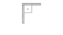
- the intra predictor 112 receives the video signal from the reorder buffer 102 when the prediction type of the CU is intra prediction, performs intra prediction, and generates an intra prediction image. As illustrated in FIG. 10, the intra predictor 112 basically sets an optimal prediction mode for each PU ( ⁇ CU), and frames a reference image including pixels adjacent to the upper end and the left end of the PU. It reads out from the memory 110, performs intra prediction according to the prediction mode based on the reference image, and generates an intra prediction image.
- the size of the intra PU is, for example, 4 ⁇ 4 pixels, 8 ⁇ 8 pixels, 16 ⁇ 16 pixels, 32 ⁇ 32 pixels, 64 ⁇ 64 pixels, or the like. Note that the intra predictor 112 may perform intra prediction in consideration of pixel positions as described later.
- the intra predictor 112 when sub-CU division is applied to divide a CU into a plurality of sub-CUs (subcoding units), the intra predictor 112 includes pixels adjacent to the left end or the upper end of the CU.
- a reference image is read from the frame memory 110, and intra prediction according to the prediction mode set for each Sub-CU is performed to generate an intra prediction image.
- the intra predictor 112 outputs the intra predicted image to the subtractor 103 and the adder 108. Furthermore, when the Sub-CU partitioning is not applied, the intra predictor 112 outputs information related to intra prediction such as information indicating the prediction mode set in the PU to the entropy encoder 115.
- the intra predictor 112 outputs a video signal and a reference image corresponding to the CU to the Sub-CU divider 113 in order to determine whether to apply or not to apply the Sub-CU partition.
- the intra predictor 112 receives information indicating application / non-application of the Sub-CU partitioning from the Sub-CU prediction mode determiner 114 and a Sub-CU partitioning method (CU is divided into a plurality of Sub-CU partitioning methods when the Sub-CU partitioning is applied. And information indicating the prediction mode set for each Sub-CU.
- the Sub-CU divider 113 divides a CU to obtain a plurality of Sub-CUs.
- a CU can be divided in various ways.
- the Sub-CU divider 113 may perform quadtree division (see FIG. 11) or binary tree division (see FIGS. 12 and 13).
- the Sub-CU divider 113 is not limited to symmetric division, and may perform asymmetric division.
- the reference images shaded areas in FIGS. 11, 12, and 13
- the reference images used for intra prediction of all the Sub-CUs belonging to the CU are common. This is very different from the case where the CU is divided into a plurality of CUs. That is, as shown in FIGS. 8 and 9, different reference images need to be read in order to intra-predict different CUs.
- the upper or left CU is decoded (ie, Start intra prediction of the lower or right CU until intra prediction, prediction difference generation, orthogonal transform, quantization, inverse quantization, inverse orthogonal transform, (loop filter processing) and decoded image generation) are completed. I can't. Therefore, according to CU partitioning, the latency related to intra prediction increases. On the other hand, according to the Sub-CU partitioning, intra prediction can be performed based on a common reference image for all the Sub-CUs belonging to the CU, so that the latency is suppressed compared to the CU partitioning. Furthermore, the intra predictor 112 can also perform intra prediction on a plurality of Sub-CUs in parallel.
- the Sub-CU divider 113 outputs a plurality of Sub-CUs to the Sub-CU prediction mode determiner 114.
- Sub-CU divider 113 may try various available Sub-CU partitioning methods to determine the optimal Sub-CU partitioning method.
- the available Sub-CU partitioning method may be one type (for example, symmetric quadtree partitioning). In this case, it is not necessary to determine an optimal Sub-CU partitioning method.
- the Sub-CU prediction mode determiner 114 receives a plurality of Sub-CUs from the Sub-CU divider 113.
- the Sub-CU prediction mode determiner 114 determines a prediction mode to be set for each Sub-CU. That is, in the sub-CU partitioning example of FIG. 11, the sub-CU prediction mode determiner 114 determines a total of four prediction modes (dir0, dir1, dir2, and dir3) for a total of four sub-CUs. 12 and FIG. 13, the Sub-CU prediction mode determiner 114 determines a total of two prediction modes (dir0 and dir1) for a total of two Sub-CUs.
- the Sub-CU prediction mode determiner 114 may try various prediction modes that can be used to determine the optimal prediction mode for each Sub-CU.
- the Sub-CU prediction mode determiner 114 compares the value of a known encoding cost function, for example, to apply / not apply Sub-CU partitioning, and to perform optimum Sub-CU partitioning when Sub-CU partitioning is applied. And the optimal prediction mode for each Sub-CU can be determined.
- the Sub-CU prediction mode determiner 114 indicates information indicating application / non-application of Sub-CU partitioning, and indicates the Sub-CU partitioning method (when there are multiple Sub-CU partitioning methods) when Sub-CU partitioning is applied. Information and information indicating the prediction mode set in each Sub-CU are output to the intra predictor 112. Further, the Sub-CU prediction mode determiner 114 also outputs information regarding these Sub-CU divisions to the entropy encoder 115.
- the information indicating application / non-application of sub-CU partitioning and the sub-CU partitioning method may be independent information, or may be integrated as one piece of information.
- This information indicates, for example, that the sub-CU partitioning is not applied with a value of “0”, and the value of “1” indicates that the sub-CU partitioning is applied and the Sub-CU partitioning method is quadtree partitioning.
- “2” and “3” may indicate that the application of Sub-CU partitioning and Sub-CU partitioning is binary tree partitioning (up / down or left / right).
- the Sub-CU prediction mode determiner 114 may select a Sub-CU prediction mode from a plurality of MPMs (hereinafter also referred to as MPM lists).
- MPM lists a plurality of MPMs (hereinafter also referred to as MPM lists).
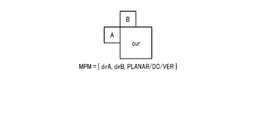
- the MPM list is determined as illustrated in FIG. That is, the three elements of the MPM list are: a prediction mode (dirA) set to the left adjacent PU of the current PU (Cur), and a prediction mode (dirB) set to the PU next to the current PU (Cur). , PLANAR mode, DC mode, or Vertical (VER) mode.
- the Sub-CU partitioning may be applied only when the size of the CU is equal to or larger than a specified value (for example, a size one step larger than the minimum size of the CU). In other words, if the size of the CU is less than the specified value, the Sub-CU partitioning may be uniformly applied. For example, since it is generally preferable to perform coding by dividing a CU finely for a fine texture region, the CU is highly likely to be divided to a minimum size. In this case, by dividing the CU (specifically, the luminance CB) into a plurality of PUs, an effect similar to that of the Sub-CU partition can be obtained, so even if the Sub-CU partition is uniformly applied.
- a specified value for example, a size one step larger than the minimum size of the CU.
- the entropy encoder 115 receives the quantized transform coefficient from the quantizer 105. Further, when the prediction type of the CU is intra prediction, the entropy encoder 115 performs information on sub-CU partitioning (that is, information indicating application / non-application of sub-CU partitioning and sub-CU partitioning). ) Is received from the Sub-CU prediction mode determiner 114, and information related to intra prediction is received from the intra predictor 112. The information indicating the Sub-CU partitioning method and the information indicating the prediction mode set for each Sub-CU is received. The entropy encoder 115 receives information related to inter prediction from the motion predictor 111 when the prediction type of the CU is inter prediction.
- sub-CU partitioning that is, information indicating application / non-application of sub-CU partitioning and sub-CU partitioning.
- 4A and 4B show the syntax used in HEVC as a comparative example.
- the CU is allowed to be divided into a plurality of PUs only when the size of the CU is the minimum (L12 to L13), 1
- a plurality of prediction modes can be set in one CU (L23 to L32).
- FIG. 14 shows an example of syntax used by the image encoding device of FIG.
- the entropy encoder 115 can perform sub-CU partitioning even when the CU is not the minimum size.
- Information indicating non-application can be encoded (L4).
- the entropy encoder 115 encodes information indicating whether to use the MPM list for luminance for each PU or Sub-CU (L9). Then, the entropy encoder 115 encodes information indicating which MPM is used for the PU or Sub-CU when the MPM list is used (L13), and otherwise sets the PU or Sub-CU.
- the information indicating the predicted mode is encoded (L15).
- the syntax of FIG. 14 has the description of L3 to L4 of FIG. 14 added, and the condition statement in L6 is merely increased by one.
- the headbin is about four times by simple calculation. Therefore, the increase of headbin by applying the Sub-CU partition is considerably smaller than that of the CU partition.
- the syntax in FIG. 14 can be rewritten to the syntax illustrated in FIG.
- the entropy encoder 115 does not need to encode information indicating whether to use the MPM list for luminance for each Sub-CU (L7 to L11). Further, the entropy encoder 115 may unconditionally encode information indicating which MPM to use for each Sub-CU (L14 to L15) when Sub-CU partitioning is applied. It is not necessary to encode information indicating the prediction mode itself set to. Therefore, according to the syntax of FIG. 15, headbin can be reduced compared with the syntax of FIG.
- nTbS size of transform block (Transform Block (TB))
- TB Transform Block
- nTbS pixels adjacent to the upper end of the PU of nTbS pixels (a, b, c in FIG. 16).
- d) and the average value of nTbS pixels (e, f, g, and h in FIG. 16) adjacent to the left end of the PU are copied to all the pixels of the PU.
- nTbS pixels a, b, c, and d in FIG.
- each of the nTbS pixels adjacent to the left end of the nTbS ⁇ nTbS pixel PU (e, f, g, and h in FIG. 16) has the same vertical position in the PU. Copied horizontally.
- any of these prediction modes if the size of the PU increases, the distance between the lower and right pixels of the PU and the reference image increases, and the difference value between these pixels and the reference image increases. Prediction efficiency may be reduced.
- the size of the PU is increased, the size of the reference image is also increased, so that the possibility that the reference image includes, for example, a picture boundary is increased.
- pixel values may differ greatly between the left and right sides of the reference image, or between the upper and lower sides of the reference image.
- the predicted value is not very similar to individual pixels in the PU, and high encoding efficiency cannot be achieved. It may be.
- the distance between the lower pixel of the PU and the pixel adjacent to the upper end of the PU increases.
- the pixel adjacent to the upper end of the PU may be greatly different from the pixel below the PU having the same horizontal position as the pixel.
- the predicted value is not very similar to the lower pixel in the PU and is high. Coding efficiency may not be achieved.
- the pixel adjacent to the left end of the PU may be greatly different from the pixel on the right side of the PU having the same vertical position as the pixel.
- the predicted values are not very similar to the pixels on the right side in the PU, and the high code Efficiency may not be achieved.
- the intra predictor 112 when the prediction mode associated with the PU is DC prediction, the intra predictor 112 considers the distribution of pixel values of the reference image and classifies the PU into a plurality of subsets under a predetermined condition. Also good. Then, the intra predictor 112 converts, for each subset, a pixel having the same horizontal position as any pixel of the subset of the reference image and a pixel having the same vertical position as any pixel of the subset. Based on this, DC prediction of the subset may be performed.
- the values of nTbS pixels (hereinafter referred to as Hor) adjacent to the upper end of the PU are on the left side (hereinafter referred to as dcHorLeft) and on the right side (hereinafter referred to as dcHorRight). If it fluctuates greatly, the PU may be divided into left and right.
- the values of nTbS pixels adjacent to the left end of the PU are on the upper side (hereinafter referred to as dcVerUp) and the lower side (hereinafter referred to as dcVerDown). )),
- the PU may be divided vertically.
- the intra predictor 112 When the PU is divided into four subsets vertically and horizontally, the intra predictor 112 generates a prediction value of each subset as follows. Upper left subset: average value of pixels belonging to dcHorLeft and pixels belonging to dcVerUp (see FIG. 17). Upper right subset: average value of pixels belonging to dcHorRight and pixels belonging to dcVerUp. Lower left subset: average value of pixels belonging to dcHorLeft and pixels belonging to dcVerDown. Lower right subset: average value of pixels belonging to dcHorRight and pixels belonging to dcVerDown.
- the intra predictor 112 When the PU is divided into two subsets on the left and right, the intra predictor 112 generates a prediction value of each subset as follows. Left subset: average value of pixels belonging to dcHorLeft and pixels belonging to Ver. Right subset: average value of pixels belonging to dcHorRight and pixels belonging to Ver.
- the intra predictor 112 determines whether or not to divide the PU vertically, whether or not the absolute value of the difference between the sum of the values of the pixels belonging to dcVerUp and the sum of the values of the pixels belonging to dcVerDown is greater than the first threshold value. It may be determined depending on. Similarly, the intra predictor 112 determines whether or not to divide the PU into left and right, and the absolute value of the difference between the sum of the values of the pixels belonging to dcHorLeft and the sum of the values of the pixels belonging to dcHorRight is greater than the second threshold. You may determine by whether it is large.
- dcVerUp and dcVerDown may have the same size or different sizes. If the two sizes are different, the difference between the average value or the median value may be calculated instead of the sum. Similarly, dcHorLeft and dcHorRight may have the same size or different sizes. If the two sizes are different, the difference between the average value or the median value may be calculated instead of the sum.
- the first threshold value and the second threshold value may be the same or different.
- the first threshold and the second threshold may be fixed, but may vary depending on, for example, the quantization parameters used by the quantizer 105 and the inverse quantizer 106. Since the quantization error increases as the quantization parameter increases, the error included in the difference may also increase. Therefore, the first threshold value and the second threshold value may be increased as the quantization parameter increases.
- an intra predictor included in an image decoding apparatus can determine which subset the PU is divided into by operating with the same algorithm as the intra predictor 112. Therefore, it is not necessary to signal information indicating what subset the PU is divided into to the image decoding apparatus. However, it is possible to implement such a method that signals such information and reduces the processing load of the intra predictor included in the image decoding apparatus.
- the intra predictor 112 calculates the prediction value (for example, the value of r2 in FIG. 18) of a given pixel (for example, cur in FIG. 18) of the PU and the pixel at the upper left corner of the PU in the reference image
- a first reference pixel for example, r0 in FIG. 18
- a second reference pixel for example, r2 in FIG. 18
- Second difference between the first difference value (difh) of the first reference pixel and a third reference pixel (for example, L2 in FIG. 18) having the same vertical position as the given pixel in the first reference pixel and the reference image. May be corrected using the difference value (difv) of the pixel and the vertical position of the given pixel.
- the intra predictor 112 may correct the predicted value of each pixel in the PU according to the following mathematical formula (1).
- difh is the first difference value described above, and is obtained by subtracting the value of the first reference pixel at position (-1, -1) from the value of the second reference pixel at position (x, -1).
- Derivable. difv is the second difference value described above, and can be derived by subtracting the value of the first reference pixel from the value of the third reference pixel at the position ( ⁇ 1, y).
- step S201 the intra predictor 112 determines a reference image of the current CU.
- this reference image includes a plurality of pixels adjacent to the left end of the current CU and a plurality of pixels adjacent to the upper end of the CU, and does not include pixels inside the CU.
- the reference image determined in step S201 is used for intra prediction of each Sub-CU.
- the image coding apparatus performs intra prediction in consideration of pixel positions as necessary. Therefore, according to this image encoding device, it is possible to suppress a decrease in prediction efficiency due to an increase in the distance between a pixel in a PU or Sub-CU and a reference image.
- the image coding apparatus increases the degree of freedom of intra prediction and enables the coding efficiency to be improved.
- the entropy decoder 302 receives the encoded bit stream from the HRD buffer 301.
- the entropy decoder 302 demultiplexes and entropy-decodes the encoded stream according to the syntax illustrated in FIG. 14 or FIG.
- the entropy decoder 302 performs entropy decoding using a codec applied in an image encoding device (not shown).
- the entropy decoder 302 may perform arithmetic coding such as CABAC and variable length coding such as CAVLC, for example.
- the entropy decoder 302 outputs the quantized transform coefficient to the inverse quantizer 303, outputs information related to inter prediction to the motion predictor 308, and stores information related to intra prediction and information related to sub-CU partitioning to the intra predictor. To 309.
- the inverse quantizer 303 receives the quantized transform coefficient from the entropy decoder 302.
- the inverse quantizer 303 inversely quantizes the quantized transform coefficient using a quantization parameter used in an image encoding device (not shown) to restore the transform coefficient.
- the inverse quantizer 303 outputs the transform coefficient to the inverse orthogonal transformer 304.
- the loop filter 306 receives the decoded image from the adder 305.
- the loop filter 306 applies a loop filter process to the decoded image.
- the loop filter process may be a deblocking filter process, a pixel adaptive offset process, or the like. Note that the deblocking filter processing is applied to the boundary pixels of the PU or TU, and reduces the subjective distortion of the block boundary. Pixel adaptive offset processing reduces ringing distortion within the block.
- the loop filter 306 outputs the filtered decoded image to the frame memory 307 and the reorder buffer 310.
- the intra predictor 309 sets a prediction mode for each PU ( ⁇ CU) based on information related to intra prediction, as illustrated in FIG.
- a reference image including pixels adjacent to is read from the frame memory 307, and intra prediction according to the prediction mode is performed based on the reference image to generate an intra prediction image.
- the intra predictor 309 determines the subset into which the PU is divided by operating with the same algorithm as the intra predictor included in the image encoding device (not shown) with respect to the DC prediction in consideration of the pixel position described above. Can be determined. Therefore, the image coding apparatus does not need to signal information indicating what subset the PU divides into. However, an implementation that signals such information and reduces the processing load of the intra predictor 309 is also possible.
- the intra predictor 309 When the Sub-CU partitioning is applied, the intra predictor 309 further receives information indicating the Sub-CU partitioning method and information indicating the prediction mode of each Sub-CU from the entropy decoder 302 (Steps S402 and S403). And step S404). If the Sub-CU partitioning method is uniquely determined, step S403 can be omitted.
- the image decoding apparatus sets a prediction mode individually for each Sub-CU and applies each Sub-CU to a common reference image when Sub-CU partitioning is applied. Predict intra. Therefore, according to this image decoding apparatus, compared with the case where a CU is divided into a plurality of CUs, a prediction mode with high prediction efficiency locally in the CU while suppressing the latency related to intra prediction and the increase of headbin. You can choose.
- the image decoding apparatus performs intra prediction in consideration of pixel positions as necessary. Therefore, according to this image decoding apparatus, it is possible to suppress a decrease in prediction efficiency due to an increase in the distance between the pixel in the PU or Sub-CU and the reference image.
- the various functional units described in the above embodiments may be realized by using a circuit.
- the circuit may be a dedicated circuit that realizes a specific function, or may be a general-purpose circuit such as a processor.
Landscapes
- Engineering & Computer Science (AREA)
- Multimedia (AREA)
- Signal Processing (AREA)
- Compression Or Coding Systems Of Tv Signals (AREA)
Abstract
Un mode de réalisation de la présente invention concerne un dispositif de décodage d'image. Le dispositif de décodage d'image comprend un décodeur et une unité d'intraprédiction. Le décodeur décode des données codées afin d'obtenir des informations indiquant s'il faut ou non appliquer une division de sous-unité de codage (sous-CU) pour diviser une unité de codage (CU) en une pluralité de sous-unités de codage et, si une division de sous-CU doit être appliquée, le décodeur obtient en outre des informations indiquant un mode de prédiction pour chaque sous-CU. Lorsqu'une division de sous-CU doit être appliquée, l'unité d'intraprédiction exécute une intraprédiction correspondant au mode de prédiction pour chaque sous-CU, afin de générer une image d'intraprédiction pour la CU, sur la base d'une image de référence qui comprend une pluralité de pixels adjacents à un bord gauche de la CU et une pluralité de pixels adjacents à un bord supérieur de la CU, mais qui ne comprend pas de pixels à l'intérieur de la CU.
Applications Claiming Priority (2)
| Application Number | Priority Date | Filing Date | Title |
|---|---|---|---|
| JP2016170869A JP2018037936A (ja) | 2016-09-01 | 2016-09-01 | 画像符号化装置および画像復号装置 |
| JP2016-170869 | 2016-09-01 |
Publications (1)
| Publication Number | Publication Date |
|---|---|
| WO2018043256A1 true WO2018043256A1 (fr) | 2018-03-08 |
Family
ID=61301754
Family Applications (1)
| Application Number | Title | Priority Date | Filing Date |
|---|---|---|---|
| PCT/JP2017/030179 Ceased WO2018043256A1 (fr) | 2016-09-01 | 2017-08-23 | Dispositif de codage d'image, et dispositif de décodage d'image |
Country Status (2)
| Country | Link |
|---|---|
| JP (1) | JP2018037936A (fr) |
| WO (1) | WO2018043256A1 (fr) |
Cited By (2)
| Publication number | Priority date | Publication date | Assignee | Title |
|---|---|---|---|---|
| WO2020182052A1 (fr) * | 2019-03-11 | 2020-09-17 | Huawei Technologies Co., Ltd. | Codeur, décodeur et procédés correspondants limitant la taille de sous-partitions à partir d'un outil de mode de codage de sous-partition intra |
| US20220167010A1 (en) * | 2019-03-11 | 2022-05-26 | Kddi Corporation | Image decoding device, image decoding method, and program |
Citations (3)
| Publication number | Priority date | Publication date | Assignee | Title |
|---|---|---|---|---|
| WO2009001864A1 (fr) * | 2007-06-28 | 2008-12-31 | Mitsubishi Electric Corporation | Codeur d'image et décodeur d'image |
| WO2011126157A1 (fr) * | 2010-04-09 | 2011-10-13 | Sharp Kabushiki Kaisha | Procédés et systèmes de prédiction intra-image |
| WO2013172984A1 (fr) * | 2012-05-14 | 2013-11-21 | Qualcomm Incorporated | Systèmes et procédés de codage vidéo intra-prédiction |
-
2016
- 2016-09-01 JP JP2016170869A patent/JP2018037936A/ja active Pending
-
2017
- 2017-08-23 WO PCT/JP2017/030179 patent/WO2018043256A1/fr not_active Ceased
Patent Citations (3)
| Publication number | Priority date | Publication date | Assignee | Title |
|---|---|---|---|---|
| WO2009001864A1 (fr) * | 2007-06-28 | 2008-12-31 | Mitsubishi Electric Corporation | Codeur d'image et décodeur d'image |
| WO2011126157A1 (fr) * | 2010-04-09 | 2011-10-13 | Sharp Kabushiki Kaisha | Procédés et systèmes de prédiction intra-image |
| WO2013172984A1 (fr) * | 2012-05-14 | 2013-11-21 | Qualcomm Incorporated | Systèmes et procédés de codage vidéo intra-prédiction |
Cited By (6)
| Publication number | Priority date | Publication date | Assignee | Title |
|---|---|---|---|---|
| WO2020182052A1 (fr) * | 2019-03-11 | 2020-09-17 | Huawei Technologies Co., Ltd. | Codeur, décodeur et procédés correspondants limitant la taille de sous-partitions à partir d'un outil de mode de codage de sous-partition intra |
| US20220167010A1 (en) * | 2019-03-11 | 2022-05-26 | Kddi Corporation | Image decoding device, image decoding method, and program |
| US11962801B2 (en) * | 2019-03-11 | 2024-04-16 | Kddi Corporation | Image decoding device, image decoding method, and program |
| US11973945B2 (en) | 2019-03-11 | 2024-04-30 | Huawei Technologies Co., Ltd. | Encoder, a decoder and corresponding methods restricting size of sub-partitions from intra sub-partition coding mode tool |
| US20240223806A1 (en) * | 2019-03-11 | 2024-07-04 | Kddi Corporation | Image decoding device, image decoding method, and program |
| US12407856B2 (en) | 2019-03-11 | 2025-09-02 | Kddi Corporation | Image decoding device, image decoding method, and program |
Also Published As
| Publication number | Publication date |
|---|---|
| JP2018037936A (ja) | 2018-03-08 |
Similar Documents
| Publication | Publication Date | Title |
|---|---|---|
| KR101581100B1 (ko) | 참조 픽쳐 리스트 관리 방법 및 이러한 방법을 사용하는 장치 | |
| WO2018061588A1 (fr) | Dispositif de codage d'image, procédé de codage d'image, programme de codage d'image, dispositif de décodage d'image, procédé de décodage d'image et programme de décodage d'image | |
| JP7728887B2 (ja) | 成分間サンプル適応オフセットにおけるコーディングの強化 | |
| TW202029774A (zh) | 藉由轉換域濾波之量化假影抑制及信號恢復 | |
| US12610040B2 (en) | Image encoding method and image decoding method | |
| KR20240006655A (ko) | 일반화된 샘플 오프셋의 적응적 적용 | |
| TWI848969B (zh) | 用於視訊寫碼及處理之解塊濾波器 | |
| JP2022093657A (ja) | 符号化装置、復号装置、及びプログラム | |
| KR20230123947A (ko) | 고정 필터들을 갖는 적응적 루프 필터 | |
| US20250392705A1 (en) | Image encoding method combining prediction modes of adjacent blocks and image decoding method | |
| KR20240046574A (ko) | 모션 벡터 예측자 정밀도를 암시적으로 지시하기 위한 방법 및 장치 | |
| JP7242930B2 (ja) | イントラ予測装置、画像復号装置、及びプログラム | |
| KR20240068697A (ko) | 서브블록 모션 벡터에 기초한 모션 벡터 예측을 위한 방법 및 장치 | |
| US20250287037A1 (en) | Image encoding method and image decoding method | |
| US20230117245A1 (en) | Image encoding method and image decoding method | |
| JP2018037936A (ja) | 画像符号化装置および画像復号装置 | |
| US12238308B2 (en) | Image encoding method and image decoding method | |
| US20260143162A1 (en) | Image encoding method and image decoding method | |
| US20260143141A1 (en) | Image encoding method and image decoding method | |
| US20260143142A1 (en) | Image encoding method and image decoding method | |
| JP7444599B2 (ja) | イントラ予測装置、画像符号化装置、画像復号装置、及びプログラム | |
| CN118786667A (zh) | 用于构建帧内模式列表的系统和方法 | |
| CN113039786A (zh) | 视频编码装置、视频编码方法、视频编码程序、视频解码装置、视频解码方法以及视频解码程序 |
Legal Events
| Date | Code | Title | Description |
|---|---|---|---|
| 121 | Ep: the epo has been informed by wipo that ep was designated in this application |
Ref document number: 17846261 Country of ref document: EP Kind code of ref document: A1 |
|
| NENP | Non-entry into the national phase |
Ref country code: DE |
|
| 122 | Ep: pct application non-entry in european phase |
Ref document number: 17846261 Country of ref document: EP Kind code of ref document: A1 |