WO2018043263A1 - Stator and manufacturing method therefor - Google Patents
Stator and manufacturing method therefor Download PDFInfo
- Publication number
- WO2018043263A1 WO2018043263A1 PCT/JP2017/030221 JP2017030221W WO2018043263A1 WO 2018043263 A1 WO2018043263 A1 WO 2018043263A1 JP 2017030221 W JP2017030221 W JP 2017030221W WO 2018043263 A1 WO2018043263 A1 WO 2018043263A1
- Authority
- WO
- WIPO (PCT)
- Prior art keywords
- yoke
- auxiliary yoke
- wall surface
- convex portion
- peripheral wall
- Prior art date
- Legal status (The legal status is an assumption and is not a legal conclusion. Google has not performed a legal analysis and makes no representation as to the accuracy of the status listed.)
- Ceased
Links
Images




Classifications
-
- F—MECHANICAL ENGINEERING; LIGHTING; HEATING; WEAPONS; BLASTING
- F16—ENGINEERING ELEMENTS AND UNITS; GENERAL MEASURES FOR PRODUCING AND MAINTAINING EFFECTIVE FUNCTIONING OF MACHINES OR INSTALLATIONS; THERMAL INSULATION IN GENERAL
- F16B—DEVICES FOR FASTENING OR SECURING CONSTRUCTIONAL ELEMENTS OR MACHINE PARTS TOGETHER, e.g. NAILS, BOLTS, CIRCLIPS, CLAMPS, CLIPS OR WEDGES; JOINTS OR JOINTING
- F16B2/00—Friction-grip releasable fastenings
- F16B2/02—Clamps, i.e. with gripping action effected by positive means other than the inherent resistance to deformation of the material of the fastening
- F16B2/06—Clamps, i.e. with gripping action effected by positive means other than the inherent resistance to deformation of the material of the fastening external, i.e. with contracting action
- F16B2/08—Clamps, i.e. with gripping action effected by positive means other than the inherent resistance to deformation of the material of the fastening external, i.e. with contracting action using bands
-
- H—ELECTRICITY
- H02—GENERATION; CONVERSION OR DISTRIBUTION OF ELECTRIC POWER
- H02K—DYNAMO-ELECTRIC MACHINES
- H02K1/00—Details of the magnetic circuit
- H02K1/06—Details of the magnetic circuit characterised by the shape, form or construction
- H02K1/12—Stationary parts of the magnetic circuit
-
- H—ELECTRICITY
- H02—GENERATION; CONVERSION OR DISTRIBUTION OF ELECTRIC POWER
- H02K—DYNAMO-ELECTRIC MACHINES
- H02K1/00—Details of the magnetic circuit
- H02K1/06—Details of the magnetic circuit characterised by the shape, form or construction
- H02K1/12—Stationary parts of the magnetic circuit
- H02K1/17—Stator cores with permanent magnets
-
- H—ELECTRICITY
- H02—GENERATION; CONVERSION OR DISTRIBUTION OF ELECTRIC POWER
- H02K—DYNAMO-ELECTRIC MACHINES
- H02K1/00—Details of the magnetic circuit
- H02K1/06—Details of the magnetic circuit characterised by the shape, form or construction
- H02K1/12—Stationary parts of the magnetic circuit
- H02K1/18—Means for mounting or fastening magnetic stationary parts on to, or to, the stator structures
- H02K1/185—Means for mounting or fastening magnetic stationary parts on to, or to, the stator structures to outer stators
-
- H—ELECTRICITY
- H02—GENERATION; CONVERSION OR DISTRIBUTION OF ELECTRIC POWER
- H02K—DYNAMO-ELECTRIC MACHINES
- H02K1/00—Details of the magnetic circuit
- H02K1/06—Details of the magnetic circuit characterised by the shape, form or construction
- H02K1/22—Rotating parts of the magnetic circuit
- H02K1/27—Rotor cores with permanent magnets
- H02K1/2786—Outer rotors
-
- H—ELECTRICITY
- H02—GENERATION; CONVERSION OR DISTRIBUTION OF ELECTRIC POWER
- H02K—DYNAMO-ELECTRIC MACHINES
- H02K15/00—Processes or apparatus specially adapted for manufacturing, assembling, maintaining or repairing of dynamo-electric machines
- H02K15/02—Processes or apparatus specially adapted for manufacturing, assembling, maintaining or repairing of dynamo-electric machines of stator or rotor bodies
- H02K15/03—Processes or apparatus specially adapted for manufacturing, assembling, maintaining or repairing of dynamo-electric machines of stator or rotor bodies having permanent magnets
-
- H—ELECTRICITY
- H02—GENERATION; CONVERSION OR DISTRIBUTION OF ELECTRIC POWER
- H02K—DYNAMO-ELECTRIC MACHINES
- H02K15/00—Processes or apparatus specially adapted for manufacturing, assembling, maintaining or repairing of dynamo-electric machines
- H02K15/14—Casings; Enclosures; Supports
-
- H—ELECTRICITY
- H02—GENERATION; CONVERSION OR DISTRIBUTION OF ELECTRIC POWER
- H02K—DYNAMO-ELECTRIC MACHINES
- H02K5/00—Casings; Enclosures; Supports
- H02K5/04—Casings or enclosures characterised by the shape, form or construction thereof
Definitions
- a belt-like auxiliary yoke having at least one convex portion formed at one end portion and at least one concave portion engaging with the convex portion at the other end portion is provided as an outer periphery of the main yoke. While being along the wall surface or the inner peripheral wall surface, the convex portion and the concave portion are rounded so as to abut along the circumferential direction of the outer peripheral wall surface and the inner peripheral wall surface of the main yoke.
- the convex portion is inserted into the concave portion.
- the convex portion is engaged with the concave portion by deforming the convex portion by pressing the tip portion of the convex portion to the peripheral end portion which is a part of the concave portion.
- the first auxiliary yoke 22 is initially formed of a rectangular belt-like plate, and on one short side, three first auxiliary yoke protrusions 22B. Are formed, and on the other short side, three first auxiliary yoke recesses 22C are formed.
- the first auxiliary yoke main body portion 22A of the belt-shaped first auxiliary yoke 22 is wound around the outer surface of the main yoke main body portion 21B.
- both yokes are reduced in diameter as shown in FIG. 9 (d), and the tip of the first auxiliary yoke convex portion 22B further extends.
- the expanded portion 226 expands to a length corresponding to the axial distance of the deformable portion 224 by being crushed.
Landscapes
- Engineering & Computer Science (AREA)
- Power Engineering (AREA)
- General Engineering & Computer Science (AREA)
- Manufacturing & Machinery (AREA)
- Mechanical Engineering (AREA)
- Iron Core Of Rotating Electric Machines (AREA)
- Manufacture Of Motors, Generators (AREA)
Abstract
Description
本出願は、当該開示内容が参照によって本出願に組み込まれた、2016年8月30日に出願された日本特許出願2016-167804号および、2017年6月5日に出願された日本特許出願2017-110944号を基にしている。 The present application includes Japanese Patent Application No. 2016-167804 filed on August 30, 2016 and Japanese Patent Application 2017 filed on June 5, 2017, the disclosures of which are incorporated herein by reference. Based on -11944.
本開示は直流モータのステータ及びその製造方法に係り、特に、ヨークに特徴を有するステータ及びその製造方法に関するものである。 The present disclosure relates to a DC motor stator and a manufacturing method thereof, and more particularly, to a stator having a feature in a yoke and a manufacturing method thereof.
直流モータの構成は、一例を挙げると、回転軸に固定された電機子及び整流子と、この電機子の外側を被覆するカップ状のヨークと、このヨークの内壁面に固定された界磁用のマグネット等を有して構成されている。このマグネットは、ヨーク内部に電機子を配設した際に、電機子の側面と対面するように構成されている。そして、カップ状のヨークの開口側はブラケットにより閉塞されている。なお、このブラケットには、回転軸を突出させるための孔が形成されており、この構成により、回転軸の出力側端部は、出力側へと突出できるように構成されている。また、ヨークの底部とブラケットの孔部付近には、軸受が配設されており、これらの軸受によって回転軸は回転可能に支持されることとなる。また、ブラケットには、ブラシが配置されており、このブラシの径方向内側端部が整流子に摺接するように構成されている。これにより、外部電源に接続されたブラシから、整流子へと電流が供給される。そして、整流子による整流により電流方向が切り替えられる電機子と、界磁用のマグネットとの相互作用によって、この電機子は回転し、ロータとして機能する。 For example, the configuration of the direct current motor includes an armature and a commutator fixed to the rotating shaft, a cup-shaped yoke covering the outside of the armature, and a field magnet fixed to the inner wall surface of the yoke. It has a magnet and the like. The magnet is configured to face the side surface of the armature when the armature is disposed inside the yoke. The opening side of the cup-shaped yoke is closed by a bracket. The bracket is formed with a hole for projecting the rotating shaft. With this configuration, the output side end of the rotating shaft can be projected to the output side. In addition, bearings are disposed in the vicinity of the bottom of the yoke and the hole of the bracket, and the rotating shaft is rotatably supported by these bearings. Moreover, the brush is arrange | positioned at the bracket and it is comprised so that the radial direction inner side edge part of this brush may slidably contact with a commutator. Thereby, a current is supplied from the brush connected to the external power source to the commutator. The armature rotates and functions as a rotor by the interaction between the armature whose current direction is switched by rectification by the commutator and the field magnet.
上記のようなヨークは、単に、電機子を被覆したりマグネットを支持するものではなく、磁気回路としての役割を果たすものである。このため、磁気回路を構築するために、ヨークの肉厚を所定以上確保する必要がある。しかしながら、従来のヨークは、磁気回路として必要な肉厚を素材板厚として絞ることにより製造されるため、磁気回路として必要の無い部分の肉厚もまた、磁気回路として必要な部分と同様の肉厚に形成される。つまり、磁気回路として必要の無い部分の肉厚が大きくなることとなる。このため、素材費用が大きくなるとともに、ヨークの質量が大きくなるという問題があった。よって、このような問題を解決するための技術が提案されている(例えば、特許文献1参照)。 The yoke as described above does not simply cover the armature or support the magnet, but serves as a magnetic circuit. For this reason, in order to construct a magnetic circuit, it is necessary to secure the thickness of the yoke at a predetermined level or more. However, since the conventional yoke is manufactured by reducing the thickness required for the magnetic circuit as the material plate thickness, the thickness of the portion that is not necessary for the magnetic circuit is also the same thickness as that required for the magnetic circuit. Thickness is formed. That is, the thickness of a portion that is not necessary as a magnetic circuit is increased. For this reason, there has been a problem that the material cost is increased and the mass of the yoke is increased. Therefore, a technique for solving such a problem has been proposed (see, for example, Patent Document 1).
特許文献1には、直流電動機のフレーム構造が開示されている。本技術においては、回転子鉄心は、カップ状のフレーム(ヨークに相当)に囲繞されており、このフレーム(ヨークに相当)の円筒部外側面には、リング状の補助フレームが配置されている。このように構成されていることで、全体としては、肉厚の小さいフレームを作成し、磁気回路として肉厚を大きくする必要がある部分は、補助フレーム(補助ヨーク)を巻装することにより、磁気回路として必要な肉厚を確保することができる。
このように、特許文献1のような技術においては、補助フレーム(補助ヨーク)を用いることで、磁気回路として必要な部分のみ肉厚を大きくし、その他の部分は肉厚を小さくすることができる。このため、フレーム(ヨーク)の素材費用低減及び軽量化を図ることができる。このような従来技術において、補助フレーム(以下、「補助ヨーク」と記す)は、カップ状のフレーム(以下、「メインヨーク」と記す)に圧入や接着によって嵌合固定されている。
As described above, in the technique such as
しかしながら、発明者の検討によると、圧入により補助ヨークをメインヨークに取付ける方法では、圧入による力によって、メインヨークが変形し、メインヨークの内径が変化してしまう。また、圧入時の力により、メインヨークや補助ヨークのメッキが剥がれる。更に、補助ヨークを圧入するためには、メインヨークの内外径を高精度に仕上げる必要があり、製造コストが高くなる。また、同様に、補助ヨークの内外径精度も要求され、製造コストが高くなる。また、接着により補助ヨークをメインヨークに取付ける方法では、密着力の低さから、補助ヨークが脱落してしまう。更に、接着剤のはみ出しにより、外観不良が発生する。この他には、溶接や絞りによる取付けがあるが、前者では、熱影響によるメインヨーク内径の変化やスポット部の腐食のおそれがあり、後者では、材料の異方性によるメインヨーク内径の精度の悪化やブランク位置決め精度の高難度化のおそれがあった。また、後者では、補助ヨークとメインヨークとの間に加工油溜りが発生する。このような状況下、メインヨークの内径を変化させることなく、高すぎる内外径精度が要求されることのない技術の開発が求められていた。 However, according to the inventors' investigation, in the method of attaching the auxiliary yoke to the main yoke by press-fitting, the main yoke is deformed by the force of press-fitting and the inner diameter of the main yoke is changed. Further, the plating of the main yoke and the auxiliary yoke is peeled off by the force during press fitting. Furthermore, in order to press-fit the auxiliary yoke, it is necessary to finish the inner and outer diameters of the main yoke with high accuracy, which increases the manufacturing cost. Similarly, the accuracy of the inner and outer diameters of the auxiliary yoke is also required, which increases the manufacturing cost. Further, in the method of attaching the auxiliary yoke to the main yoke by bonding, the auxiliary yoke falls off due to low adhesion. Furthermore, the appearance failure occurs due to the protrusion of the adhesive. In addition to this, there is welding or drawing attachment, but in the former, there is a risk of changes in the inner diameter of the main yoke due to thermal effects and corrosion of the spot part, and in the latter, the accuracy of the inner diameter of the main yoke due to material anisotropy is affected. There was a risk of deterioration or increased blank positioning accuracy. In the latter case, a working oil pool is generated between the auxiliary yoke and the main yoke. Under such circumstances, there has been a demand for the development of a technique that does not require an excessively high inner / outer diameter accuracy without changing the inner diameter of the main yoke.
本開示の目的は、上記点を鑑み、メインヨークに補助ヨークが取付けられた際、この取付によるメインヨークへの影響を抑制することができるよう構成されたステータ及びその製造方法を提供することにある。 In view of the above points, an object of the present disclosure is to provide a stator configured to suppress an influence on the main yoke due to the attachment when the auxiliary yoke is attached to the main yoke, and a method for manufacturing the stator. is there.
また、本開示の他の目的は、メインヨークや補助ヨークの内外径の精度要求を低減し、製造コスト的に有利なステータ及びその製造方法を提供することにある。 Also, another object of the present disclosure is to provide a stator that is advantageous in terms of manufacturing cost and a manufacturing method thereof that reduce accuracy requirements of the inner and outer diameters of the main yoke and the auxiliary yoke.
本開示に係るステータによれば、回転電機を構成し、回転軸に固定された電機子を格納する有底筒状のステータである。該ステータは、有底筒状のメインヨークと、該メインヨークの外周壁面若しくは内周壁面に配置された帯状の補助ヨークと、前記メインヨークの内部において、前記電機子の外側面と径方向に対向するように配置された界磁用マグネットと、を備える。前記補助ヨークは、前記メインヨークの外周壁面若しくは内周壁面の周方向に沿って配置されている。前記補助ヨークの一端部には、少なくとも1個の凸部が形成されている。前記補助ヨークの他端部には、前記補助ヨークが前記周方向に沿って前記メインヨークの外周壁面若しくは内周壁面に配置された状態で前記周方向において前記凸部と対向して係合している少なくとも1個の凹部が形成されている。 The stator according to the present disclosure is a bottomed cylindrical stator that constitutes a rotating electric machine and houses an armature fixed to a rotating shaft. The stator includes a bottomed cylindrical main yoke, a belt-like auxiliary yoke disposed on the outer peripheral wall surface or the inner peripheral wall surface of the main yoke, and the outer surface of the armature in the radial direction inside the main yoke. And a field magnet disposed so as to face each other. The auxiliary yoke is disposed along the circumferential direction of the outer peripheral wall surface or the inner peripheral wall surface of the main yoke. At least one convex portion is formed at one end of the auxiliary yoke. The other end portion of the auxiliary yoke is engaged with the auxiliary yoke so as to face the convex portion in the circumferential direction in a state where the auxiliary yoke is disposed on the outer peripheral wall surface or the inner peripheral wall surface of the main yoke along the circumferential direction. At least one recess is formed.
このように、本開示において、補助ヨークは、メインヨークの外周壁面若しくは内周壁面の周方向に沿って配置されており、補助ヨークの周方向一端部と他端部に各々形成された凸部と凹部とが、周方向に突き合わされて係合している構成とした。 As described above, in the present disclosure, the auxiliary yoke is disposed along the circumferential direction of the outer peripheral wall surface or the inner peripheral wall surface of the main yoke, and the convex portions respectively formed at one end portion and the other end portion in the circumferential direction of the auxiliary yoke. And the recess are abutted and engaged in the circumferential direction.
これにより、補助ヨークの配置において、圧入等による物理的に大きな力がかからず、メインヨークに影響が及ぶこと(内径が変化する、メッキ剥がれ等)を有効に防止することができる。また、溶接よる化学的な力による影響(熱変性、腐食、異方性変化)もまた有効に防止でき、絞りによる油溜りの慮もなくなる。同様に接着の際に懸念される脱落や外観不良の慮もなくなる。また、係合する構成であるため、メインヨークや補助ヨークの内外径の精度要求を低減でき、製造コスト的に有利である。 Thereby, in the arrangement of the auxiliary yoke, it is possible to effectively prevent the main yoke from being physically applied by press-fitting or the like and affecting the main yoke (inner diameter changes, plating peeling, etc.). Moreover, the influence (thermal denaturation, corrosion, anisotropy change) due to chemical force caused by welding can also be effectively prevented, and there is no need for oil stagnation due to squeezing. Similarly, there is no need to worry about dropout or poor appearance, which is a concern during bonding. Further, since the engaging structure is used, the accuracy requirements of the inner and outer diameters of the main yoke and the auxiliary yoke can be reduced, which is advantageous in terms of manufacturing cost.
このとき、具体的な構成としては、前記凹部の一部には、前記凸部が圧接した状態で係合してもよい。係合剛性が高くなる。 At this time, as a specific configuration, a part of the concave portion may be engaged with the convex portion in pressure contact. Engagement rigidity is increased.
また、具体的な構成としては、前記凹部は、該凹部の開口により近い第1孔部と、該第1孔部よりも前記開口から離れており前記第1孔部と連通した第2孔部と、を有してもよい。前記第1孔部の軸方向距離は、前記第2孔部の軸方向距離よりも小さくてもよい。前記凸部の先端部には、前記凸部の先端部が押し潰れて軸方向距離が長くなるように拡がった拡がり部が設けられてもよい。前記凸部は、前記拡がり部において前記凸部の基端部側に位置する表面が前記第1孔部と前記第2孔部との間に形成された段差に密接した状態で前記凹部に係合してもよい。このように構成されていると、凸部と凹部をより強固に係合させ、凹部から凸部が離脱することを有効に防止することが可能となる。 As a specific configuration, the recess includes a first hole closer to the opening of the recess and a second hole that is further away from the opening than the first hole and communicates with the first hole. You may have. The axial distance of the first hole may be smaller than the axial distance of the second hole. The front end portion of the convex portion may be provided with a widened portion that expands such that the front end portion of the convex portion is crushed and the axial distance is increased. The convex portion is engaged with the concave portion in a state in which a surface of the expanded portion located on the base end side of the convex portion is in close contact with a step formed between the first hole portion and the second hole portion. May be combined. If comprised in this way, it will become possible to engage a convex part and a recessed part more firmly, and to prevent effectively that a convex part detach | leaves from a recessed part.
更に、具体的な適用構成としては、前記凹部の開口部の軸方向距離は、内部の軸方向距離よりも小さくなるように形成されてもよい。前記凸部の先端部側は、前記凹部の内部に配置されてもよい。前記凸部の先端は、前記凹部の内部を規定する周縁部の一部に圧接しており、前記凸部の基端部側は、前記凸部の先端部側よりも軸方向距離が小さくなるように構成されるとともに、前記凹部の開口部に配置されてもよい。このように構成されていると、係合した後に、凹部から凸部が離脱することを有効に防止することができ、確実かつ効率的に係合させることが可能となる。 Furthermore, as a specific application configuration, the axial distance of the opening of the recess may be formed to be smaller than the internal axial distance. The front end portion side of the convex portion may be disposed inside the concave portion. The tip of the convex portion is in pressure contact with a part of the peripheral edge that defines the inside of the concave portion, and the proximal end side of the convex portion has a smaller axial distance than the tip end side of the convex portion. It may be arranged and it may be arranged in the opening of the recess. If comprised in this way, after engaging, it can prevent effectively that a convex part detaches | leaves from a recessed part, and it becomes possible to engage reliably and efficiently.
また、前記凸部の近傍及び前記凹部の近傍のうち少なくとも一方側には、緩衝孔が形成されていると、凹部への凸部の係合力を逃がすための逃げ孔となるため、他の箇所への係合力の影響を低減することができる。 In addition, if a buffer hole is formed in at least one of the vicinity of the convex part and the vicinity of the concave part, it becomes a relief hole for escaping the engaging force of the convex part to the concave part. The influence of the engaging force on can be reduced.
また、本開示の係るステータによれば、回転電機を構成し、回転軸に固定された電機子を格納する有底筒状のステータである。該ステータは、有底筒状のメインヨークと、該メインヨークの外周壁面若しくは内周壁面に配置され、帯状の板体である補助ヨーク本体部の一端部と他端部とが連絡されて筒状となった補助ヨークと、前記メインヨークの内部において、前記電機子の外側面と径方向に対向するように配置された界磁用マグネットと、を備える。前記補助ヨークは、前記メインヨークの外周壁面若しくは内周壁面の周方向に沿って配置されている。前記補助ヨーク本体部の一端部と他端部とは、一方側を他方側へと引き寄せる若しくは引き離すように回動可能な回動かしめ部を介して周方向に連結されている。前記補助ヨークは、前記ヨークの内周壁面若しくは外周壁面に圧接している。 Further, according to the stator according to the present disclosure, it is a bottomed cylindrical stator that constitutes a rotating electric machine and stores an armature fixed to a rotating shaft. The stator is disposed on the bottomed cylindrical main yoke and on the outer peripheral wall surface or the inner peripheral wall surface of the main yoke, and one end and the other end of the auxiliary yoke main body, which is a belt-shaped plate body, are connected to each other. And a field magnet disposed in the main yoke so as to face the outer surface of the armature in the radial direction. The auxiliary yoke is disposed along the circumferential direction of the outer peripheral wall surface or the inner peripheral wall surface of the main yoke. One end portion and the other end portion of the auxiliary yoke main body portion are connected in the circumferential direction via a rotation caulking portion that can be rotated so as to draw one side toward or away from the other side. The auxiliary yoke is in pressure contact with the inner peripheral wall surface or the outer peripheral wall surface of the yoke.
そして、このとき、具体的な構成としては、前記回動かしめ部は、平板状の作用部と、該作用部の一方点と前記補助ヨーク本体部の一端部とを連結する一方側連結部と、前記作用部の他方点と前記補助ヨーク本体部の他端部とを連結する他方側連結部と、を備えてもよい。前記他方点は、前記作用部の中心に対して、前記一方点と点対称の位置に形成されてもよい。このように構成されていると、回動かしめ部を回動させるのみで、補助ヨークをメインヨークに装着することができる。よって、上記凸部と凹部の係合と同様の各種作用効果を奏することができる。 At this time, as a specific configuration, the swaging caulking portion includes a plate-like action portion, and one side connection portion that connects one point of the action portion and one end portion of the auxiliary yoke body portion. The other side connection part which connects the other point of the said action part, and the other end part of the said auxiliary | assistant yoke main-body part may be provided. The other point may be formed at a point-symmetrical position with respect to the one point with respect to the center of the action portion. If comprised in this way, an auxiliary | assistant yoke can be mounted | worn with a main yoke only by rotating a rotation caulking part. Therefore, various effects similar to the engagement between the convex portion and the concave portion can be obtained.
更に、上述した構成において、前記凸部及び前記凹部、又は、前記回動かしめ部は、前記界磁用マグネットの重心位置と径方向に整合する位置近傍に少なくとも備えられてもよい。界磁用マグネットにおいて、当該箇所は、磁路として活用しない場所であり、当該箇所に、凸部と凹部の係合部分、若しくは回動かしめ部を配置してもよい。これによれば、磁気損失の影響を受けない。 Furthermore, in the above-described configuration, the convex portion and the concave portion, or the rotating caulking portion may be provided at least in the vicinity of a position that is aligned in the radial direction with the gravity center position of the field magnet. In the field magnet, the location is a location that is not used as a magnetic path, and an engaging portion of a convex portion and a concave portion, or a rotation caulking portion may be arranged at the location. According to this, it is not influenced by magnetic loss.
また、本開示に係るステータの製造方法は、有底筒状のメインヨークと、該メインヨークの内周壁面若しくは外周壁面に配置された帯状の補助ヨークと、前記メインヨークの内部において、電機子の外側面と径方向に対向するように配置された界磁用マグネットと、を備えて構成され、回転軸に固定された前記電機子を格納するステータを製造する方法である。当該ステータを製造する方法は、配置工程と、挿入工程と、圧接工程と、を有する。配置工程では、一端部に少なくとも1個の凸部が形成されるとともに、他端部に前記凸部と係合する少なくとも1個の凹部が形成された帯状の補助ヨークを、前記メインヨークの外周壁面若しくは内周壁面に沿わせながら、前記メインヨークの外周壁面及び内周壁面の周方向に沿って前記凸部と前記凹部とが突き合うように丸める。挿入工程では、前記凹部に対し、前記凸部を挿入する。圧接工程では、前記凹部の一部である周端部に前記凸部の先端部を圧接させて前記凸部を変形させることにより、前記凹部に前記凸部を係合させる。 In addition, a stator manufacturing method according to the present disclosure includes a bottomed cylindrical main yoke, a strip-shaped auxiliary yoke disposed on an inner peripheral wall surface or an outer peripheral wall surface of the main yoke, and an armature in the main yoke. And a field magnet disposed so as to face the outer side surface of the magnet in a radial direction, and a stator for storing the armature fixed to the rotating shaft. The method for manufacturing the stator includes an arrangement step, an insertion step, and a pressure contact step. In the arranging step, a belt-like auxiliary yoke having at least one convex portion formed at one end portion and at least one concave portion engaging with the convex portion at the other end portion is provided as an outer periphery of the main yoke. While being along the wall surface or the inner peripheral wall surface, the convex portion and the concave portion are rounded so as to abut along the circumferential direction of the outer peripheral wall surface and the inner peripheral wall surface of the main yoke. In the insertion step, the convex portion is inserted into the concave portion. In the pressure contact step, the convex portion is engaged with the concave portion by deforming the convex portion by pressing the tip portion of the convex portion to the peripheral end portion which is a part of the concave portion.
このとき、前記挿入工程及び前記圧接工程は、2つの分割金型の間に形成される収容空間内に、前記メインヨーク及び前記メインヨークの外周壁面に巻き付けられた前記補助ヨークを収容した状態で行われてもよい。前記収容空間内の前記メインヨーク及び前記補助ヨークを、前記2つの分割金型によって挟み込んで前記メインヨークの径方向に加圧することで、前記凹部に対して前記凸部を挿入して前記凹部に前記凸部を係合させてもよい。このように、分割された2つの金型の間にメインヨーク及び補助ヨークを挟み込んでメインヨークの径方向に加圧することにより、簡単に補助ヨークをメインヨークの外周壁面に巻き付けることができるとともに、凸部を凹部に容易に係合させることが可能となる。 At this time, in the insertion step and the pressure contact step, the main yoke and the auxiliary yoke wound around the outer peripheral wall surface of the main yoke are accommodated in an accommodation space formed between two divided molds. It may be done. The main yoke and the auxiliary yoke in the housing space are sandwiched between the two split molds and pressed in the radial direction of the main yoke, so that the convex portion is inserted into the concave portion to the concave portion. The convex portion may be engaged. Thus, by sandwiching the main yoke and the auxiliary yoke between the two divided molds and pressurizing in the radial direction of the main yoke, the auxiliary yoke can be easily wound around the outer peripheral wall surface of the main yoke, The convex portion can be easily engaged with the concave portion.
また、上記の方法において、前記凸部には、吸収孔が形成されており、前記圧接工程では、前記吸収孔を変形させることにより、前記凹部内で前記凸部の先端部分を変形させて前記凹部に前記凸部を係合してもよい。 Further, in the above method, an absorption hole is formed in the convex portion, and in the pressing step, the absorption hole is deformed to deform a tip portion of the convex portion in the concave portion. The convex portion may be engaged with the concave portion.
このように、帯状の補助ヨークを巻き付け、凸部と凹部とを周方向に突き合わせるとともに、両者を係合させることで補助ヨークを装着する構成とした。このため、上記同様の作用効果を奏することができる。 Thus, the belt-shaped auxiliary yoke is wound, the convex portion and the concave portion are butted in the circumferential direction, and the auxiliary yoke is mounted by engaging both. For this reason, there can exist an effect similar to the above.
また、圧接工程では、凸部の先端を凹部に圧接させて、凹部を変形させながら(潰しながら)凹部に係合させる。このため、周方向に力を加えるのみで係合させることができる。また、圧接工程後は凸部は凹部内部で変形しているため(潰れているため)、凹部から凸部が離脱することを有効に防止することができる。このように、簡易かつ確実に凸部を凹部に係合させることができる。 Also, in the pressure contact process, the tip of the convex portion is pressed against the concave portion and engaged with the concave portion while being deformed (crushed). For this reason, it can be engaged only by applying force in the circumferential direction. Moreover, since the convex part is deform | transforming inside the recessed part (being crushed) after a press-contacting process, it can prevent effectively that a convex part detaches | leaves from a recessed part. Thus, the convex portion can be engaged with the concave portion easily and reliably.
また、凸部の先端部に吸収孔が形成されているため、圧接工程にて凸部を変形させる(潰す)際に、この吸収孔がクッションとなり、凸部が割れることを防止することができるとともに、この吸収孔が形成されていることで、凸部を変形させる(潰す)ための力を小さくすることができる。 Moreover, since the absorption hole is formed in the front-end | tip part of a convex part, when deforming (crushing) a convex part at a press-contact process, this absorption hole becomes a cushion and can prevent a convex part from being cracked. At the same time, since the absorption hole is formed, the force for deforming (crushing) the convex portion can be reduced.
更に、本開示に係るステータの製造方法は、有底筒状のメインヨークと、該メインヨークの外周壁面若しくは内周壁面に配置された補助ヨークと、前記メインヨークの内部において、電機子の外側面と径方向に対向するように配置された界磁用マグネットと、を備えて構成され、回転軸に固定された前記電機子を格納するステータを製造する方法である。当該ステータを製造する方法は、配置工程と、挿入工程と、圧接工程と、を有する。配置工程では、帯状の板体である補助ヨーク本体部の一端部と他端部とを連絡するとともに、回動することにより一方側を他方側へと引き寄せる若しくは引き離す回動かしめ部によって連結されて筒状となった前記補助ヨークを、前記メインヨークの外周壁面若しくは内周壁面に装着する。圧接工程では、前記回動かしめ部を回動させて、前記補助ヨーク本体部の端部の一方側を他方側へと引き寄せる若しくは引き離すことにより、前記補助ヨークを前記メインヨークの外周壁面若しくは内周壁面に圧接させる。 Further, the stator manufacturing method according to the present disclosure includes a bottomed cylindrical main yoke, an auxiliary yoke disposed on an outer peripheral wall surface or an inner peripheral wall surface of the main yoke, and an outer armature inside the main yoke. And a field magnet arranged so as to face the side surface in the radial direction, and a stator for storing the armature fixed to the rotating shaft. The method for manufacturing the stator includes an arrangement step, an insertion step, and a pressure contact step. In the placement step, the auxiliary yoke main body part, which is a belt-shaped plate body, communicates with one end part and the other end part, and is connected by a rotating caulking part that pulls or pulls one side to the other side by rotating. The cylindrical auxiliary yoke is mounted on the outer peripheral wall surface or inner peripheral wall surface of the main yoke. In the press-contacting process, the auxiliary caulking portion is rotated to draw one side of the end portion of the auxiliary yoke main body portion toward or away from the other side, whereby the auxiliary yoke is moved to the outer peripheral wall surface or inner peripheral surface of the main yoke. Press against the wall.
このように構成されていることで、回動かしめ部を回動させるのみで、メインヨークに補助ヨークを簡易に装着することができ、上記と同様の各作用効果を奏することができる。 With this configuration, the auxiliary yoke can be easily attached to the main yoke simply by rotating the swaging caulking portion, and the same functions and effects as described above can be achieved.
本開示に係るステータは、メインヨークに対して補助ヨークを装着する構成を採る。そして、この際、圧入、溶接、絞り、接着等が不要である。つまり、物理的に大きな力の影響や化学的な影響を受けることを防止することができる。このため、メインヨークの内径変化、メッキ剥がれ、熱変性、腐食、異方性変化、油溜り、補助ヨークの脱落、外観不良等を有効に防止することができる。また、係合する構成、若しくは回動かしめ部を回動させて補助ヨークの径を調整する構成であるため、メインヨークや補助ヨークの内外径の精度要求が低減され、製造コスト的にも有利である。 The stator according to the present disclosure adopts a configuration in which an auxiliary yoke is attached to the main yoke. At this time, press-fitting, welding, drawing, bonding, etc. are unnecessary. In other words, it is possible to prevent physical influences and chemical influences. For this reason, it is possible to effectively prevent changes in the inner diameter of the main yoke, peeling of the plating, thermal denaturation, corrosion, change in anisotropy, oil sump, dropping off of the auxiliary yoke, poor appearance, and the like. In addition, since the engaging structure or the rotating caulking portion is rotated to adjust the diameter of the auxiliary yoke, the required accuracy of the inner and outer diameters of the main yoke and the auxiliary yoke is reduced, which is advantageous in terms of manufacturing cost. It is.
以下に、図面を参照しながら本開示を実施するための複数の形態を説明する。各形態において先行する形態で説明した事項に対応する部分には同一の参照符号を付して重複する説明を省略する場合がある。各形態において構成の一部のみを説明している場合は、構成の他の部分については先行して説明した他の形態を適用することができる。各実施形態で具体的に組合せが可能であることを明示している部分同士の組合せばかりではなく、特に組合せに支障が生じなければ、明示してなくとも実施形態同士を部分的に組み合せることも可能である。以下、本開示の実施形態を図面に基づいて説明する。なお、以下に説明する構成は本開示を限定するものでなく、本開示の趣旨の範囲内で種々改変することができるものである。 Hereinafter, a plurality of modes for carrying out the present disclosure will be described with reference to the drawings. In each embodiment, parts corresponding to the matters described in the preceding embodiment may be denoted by the same reference numerals, and redundant description may be omitted. When only a part of the configuration is described in each mode, the other modes described above can be applied to the other parts of the configuration. Not only combinations of parts that clearly show that combinations are possible in each embodiment, but also combinations of the embodiments even if they are not explicitly stated unless there is a problem with the combination. Is also possible. Hereinafter, embodiments of the present disclosure will be described with reference to the drawings. Note that the configuration described below does not limit the present disclosure and can be variously modified within the scope of the gist of the present disclosure.
本実施形態は、補助ヨークを装着するにあたり、メインヨークに対する物理的影響を軽減するとともに、簡易に補助ヨークの装着を実施することができるステータとその製造方法について説明するものである。 This embodiment describes a stator that can reduce the physical influence on the main yoke when mounting the auxiliary yoke, and can easily mount the auxiliary yoke, and a manufacturing method thereof.
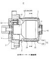
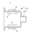
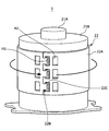
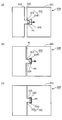
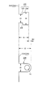
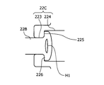
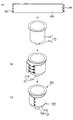
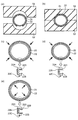
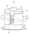
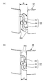
図1乃至図12は、本開示を例示するものであり、図1は第1実施形態及び第2実施形態に共通するモータの概略構成図を示した。図2乃至図7は、第1実施形態を示すものであり、図2は第1ステータの縦断面相当図、図3は第1ステータの斜視図、図4は図1のA-A線断面図及び平面図、図5は第1補助ヨークの取付部分を示す説明図、図6は第1補助ヨークの取付部分のサイズ構成を示す説明図、図7は第1補助ヨークの取付部分の変形例を示す図、図8は第1ステータの製造工程を示す説明図、図9は第1ステータの製造工程に関するバリエーションを示す図である。なお、図2は、第1ステータの説明のため、ステータとマグネットのみを示し、その他の図示は省略している。図10乃至図12は、第2実施形態を示すものであり、図10は第2ステータを示す斜視図、図11は第2補助ヨークの回動かしめ部を示す説明図である。また、図12には、この回動かしめ部の機能を詳細に説明する説明図を示した。 1 to 12 exemplify the present disclosure, and FIG. 1 shows a schematic configuration diagram of a motor common to the first embodiment and the second embodiment. 2 to 7 show the first embodiment. FIG. 2 is a view corresponding to a longitudinal section of the first stator, FIG. 3 is a perspective view of the first stator, and FIG. 4 is a section taken along line AA in FIG. FIG. 5 is an explanatory diagram showing a mounting portion of the first auxiliary yoke, FIG. 6 is an explanatory diagram showing a size configuration of the mounting portion of the first auxiliary yoke, and FIG. 7 is a modification of the mounting portion of the first auxiliary yoke. FIG. 8 is a diagram illustrating an example, FIG. 8 is an explanatory diagram showing a manufacturing process of the first stator, and FIG. FIG. 2 shows only the stator and the magnet for the explanation of the first stator, and the other illustrations are omitted. 10 to 12 show a second embodiment, FIG. 10 is a perspective view showing a second stator, and FIG. 11 is an explanatory view showing a rotating caulked portion of a second auxiliary yoke. FIG. 12 shows an explanatory diagram for explaining the function of the swaging caulking portion in detail.
<<第1実施形態>><モータの概略構成について>
当該例示したモータMは、直流モータである。以下、モータMの構成について簡単に説明する。本実施形態に係るモータMは、ロータ1と、第1ステータ2と、エンドプレート3と、ブラシ4と、を組み合わせることにより構成されている。なお、モータMの出力側とは、モータMの動力が伝達されていく側であり、図1においては、向かって左側を指す。また、基端部側とは、回転軸11の軸方向に沿って、出力側と反対側を指すものとする。
<< First Embodiment >><< General Configuration of Motor >>
The illustrated motor M is a DC motor. Hereinafter, the configuration of the motor M will be briefly described. The motor M according to the present embodiment is configured by combining the
図1に示すように、ロータ1は、回転中心となる回転軸11と、電機子12と、整流子13と、を有して構成されている。電機子12は、回転軸11と一体回転可能に組付けられるものであり、ロータコア12Aと、このロータコア12Aに巻装されるコイル12Bと、を有して構成されている。円筒形状の整流子13は、回転軸11に固定されるが、この固定位置は、電機子12によりも出力側であり、回転軸11と一体的に回転可能である。そして、電機子12を構成するコイル12Bは、整流子13(正確には、外周に貼設された整流子片)と電気的に接続されている。
As shown in FIG. 1, the
第1ステータ2は、カップ形状のメインヨーク21と、このメインヨーク21の外側に配置される円環形状の第1補助ヨーク22と、界磁用のマグネット23と、を有して構成されている。メインヨーク21のカップ形状底面部分の中央部には、基端部方向に突出するカップ形状の軸受配設部21Aが形成されている。なお、この軸受配設部21A以外の部分を「メインヨーク本体部21B」と記す。この軸受配設部21Aの内部には、円環状のボール軸受K1が配置されており、このボール軸受K1により、回転軸11の基端部側端部が回転可能に軸支されている。また、界磁用のマグネット23は、瓦型の永久磁石であり、メインヨーク本体部21Bの内側壁に複数個(極数に対応する個数)貼設されている。なお、本例においては、4極を例示しているため、4個のマグネット23が使用されている。
The
メインヨーク21は、カップ形状(有底筒状)の磁性体であり、特に、メインヨーク本体部21Bは、内壁に貼設されているマグネット23,23間を磁束で結合して磁気回路を構成する役割を果たす。第1補助ヨーク22は、円環形状の磁性体であり、メインヨーク本体部21Bの外側面(外周壁面に相当)に巻き付くように配置され、メインヨーク21の磁気回路としての役割を補強するものである。なお、このメインヨーク21への第1補助ヨーク22の取付構造等に関しては、本開示の主要構成であるため、後に詳述する。
The
また、メインヨーク21の開口側は、エンドプレート3(ブラシホルダ)で閉塞されている。このエンドプレート3の中央部には、回転軸11の出力側を貫通させるための貫通孔(図示せず)が形成されており、この貫通孔の内壁面には、円環状のボール軸受K2が配置されている。このボール軸受K2により、回転軸11の出力側が回転可能に軸支されている。更に、エンドプレート3の基端部側の面には、ブラシ4が配置されている。このブラシ4は、角柱状の部材であり、径方向中央側の端部が整流子13の外側面(正確には、外周に貼設された整流子片)に当接するように構成されている。
Further, the opening side of the
以上のように、カップ状の第1ステータ2の内部には、ロータ1を構成する電機子12が格納されており、第1ステータ2の開口部(出力側に開口している)は、回転軸11の出力側端部を突出させた状態で、エンドプレート3で閉塞されている。そして、この状態において、回転軸11の基端部側端部及び出力側端部は、ボール軸受K1,K2により回転可能に軸支されるとともに、エンドプレート3の出力側面に配置されたブラシ4は、整流子13の外側面に当接している。なお、第1ステータ2を構成するメインヨーク本体部21Bの内側面には、界磁用のマグネット23が貼設されており、このマグネット23は、電機子12の外側面と対面するように構成されている。
As described above, the
そして、図示は省略するが、ブラシ4には、外部電源から電流が供給されるよう構成されており、このブラシ4から供給される電流は、整流子13により整流されて電機子12に供給される。そして、磁力方向が切替わる電磁石となった電機子12と、固定された界磁用のマグネット23との相互作用によりロータ1が回転することとなる。そして、この第1ステータ2は、メインヨーク21と第1補助ヨーク22とを組合わせて1個のヨークとしたものであり、本例においては、メインヨーク21の外側面に円環状の第1補助ヨーク22が配設された構成となっている。なお、本実施形態においては、第1補助ヨーク22が、メインヨーク21の外側面に配置された構成を説明するが、もちろん、これに限られることはなく、メインヨーク21の内側面(内周壁面に相当)に円環状の第1補助ヨーク22が配置された構成とし、この第1補助ヨーク22の内側面にマグネット23が配設される構成としてもよい。しかしながら、製造における作業性等を鑑みると、第1補助ヨーク22は、メインヨーク21の外側面に配置される構成がより好適な構成である。
Although not shown, the
<第1補助ヨークの構成について>
図3乃至図7により、本実施形態に係る第1補助ヨーク22の構造について説明する。本実施形態に係る第1補助ヨーク22は、長方形帯状の板状体を環状に丸めることにより構成された円筒状の部材である。本実施形態に係る第1補助ヨーク22は、図3に示すように、第1補助ヨーク本体部22Aと、第1補助ヨーク凸部22Bと、第1補助ヨーク凹部22Cと、を有して構成されている。第1補助ヨーク本体部22Aは、長方形状(帯状)の板体であり、環状に丸めることにより円筒形状となる部分である。なお、以下、説明のため、長方形状の第1補助ヨーク本体部22Aの長辺を「長辺221」と記し、短辺を「短辺222」と記す。長辺221は、メインヨーク本体部21Bの外側面の胴回りの長さと略同じ長さとなるように構成されている。
<Configuration of the first auxiliary yoke>
The structure of the first
また、第1補助ヨーク凸部22Bは、第1補助ヨーク本体部22Aの一方の短辺222(すなわち、第1補助ヨーク22の一端部)に形成されている。第1補助ヨーク凹部22Cは、第1補助ヨーク本体部22Aの他方の短辺222(すなわち、第1補助ヨーク22の他端部)に形成されている。第1補助ヨーク凸部22Bは、一方の短辺222から、長辺221が延びる方向へと突出した突起である。なお、本実施形態において、第1補助ヨーク凸部22Bの先端部分は、当初、円弧状に形成されている。そして、第1補助ヨーク凸部22Bには、図5に示すように、吸収孔H1が形成(厳密には、中抜き形成)されている。後述するが、この吸収孔H1は、第1補助ヨーク凸部22Bを第1補助ヨーク凹部22C内で変形するときに逃げ孔となる部分である。なお、本実施形態において、図3に示すように、第1補助ヨーク凸部22Bは、軸方向に並列するように3個形成されている。
The first auxiliary yoke
第1補助ヨーク凹部22Cは、他方の短辺222から、長辺221が延びる方向に沿って穿たれた凹部である。本実施形態において、第1補助ヨーク凹部22Cは、図5に示すように、挿入部223と変形部224とを有して構成されている。挿入部223は、第1補助ヨーク凹部22Cの開口により近い第1孔部に相当し、他方の短辺222から切り込まれた矩形の孔部である。変形部224は、第2孔部に相当し、挿入部223よりも第1補助ヨーク凹部22Cの開口から離れており、挿入部223と連通する矩形孔部である。そして、挿入部223の軸方向距離(開口幅)は、第1補助ヨーク凸部22B基端部の軸方向距離(軸方向長さ)とほぼ同等となるように構成されるとともに、変形部224の軸方向距離よりも小さくなるように構成されている。つまり、第1補助ヨーク凹部22Cは、入口側(一方の短辺222端部側)が狭い孔部(挿入部223)であって、奥側が広い孔部(変形部224)となるように、長辺221が延びる方向に沿って穿たれた(一方の短辺222から他方の短辺222に向かって穿たれた)スリット状の孔部である。より詳しく説明すると、図5に示すように、挿入部223と変形部224との間には、L字状の段差225が形成されている。なお、本実施形態においては、図3に示すように、第1補助ヨーク凹部22Cが軸方向に並列するように3個形成されており、第1補助ヨーク本体部22Aを環状に丸めて両短辺222,222を合わせた際に、3個の第1補助ヨーク凸部22Bが、3個の第1補助ヨーク凹部22Cの位置に整合するように位置が決定されている。
The first
なお、本実施形態では、図3に示すように、第1補助ヨーク凸部22Bの基端部側付近と、第1補助ヨーク凹部22Cの変形部224付近とに緩衝孔H2が形成されている。これら緩衝孔H2は、第1補助ヨーク凸部22Bを第1補助ヨーク凹部22Cに係合した際に、この係合作業によって加えられる力及びこの力による変形が、第1補助ヨーク本体部22Aのその他の部分(係合作業が行われる端部以外の部分)に及ぶことを防止するための緩衝部分となる。すなわち、第1補助ヨーク本体部22Aを環状に丸めて両短辺222,222を合わせる際、第1補助ヨーク凸部22Bの先端が第1補助ヨーク凹部22C内に嵌まり込んで吸収孔H1が変形し、両短辺222,222が密着した状態から更に第1補助ヨーク凸部22Bの先端部を第1補助ヨーク凹部22Cの奥側に向かって押し込むと、緩衝孔H2がその機能を発揮するために変形する。
In the present embodiment, as shown in FIG. 3, buffer holes H2 are formed in the vicinity of the base end side of the first auxiliary yoke
また、本実施形態においては、図4に示すように、第1補助ヨーク22の継ぎ目部分、つまり、一方の短辺222と他方の短辺222とが突き合わされている部分は、マグネット23が配置されている位置の外側に配置されるように構成されている。好適には、図4の(b)に示すように、上記の突き合せ部分が、周方向においてマグネット23が配設された範囲内に位置しているのが望ましい。また、第1補助ヨーク凸部22Bと第1補助ヨーク凹部22Cとの係合位置は、マグネット23の重心位置と径方向に整合する位置であると更に望ましい。本実施形態においては、3個の第1補助ヨーク凸部22Bと3個第1補助ヨーク凹部22Cとが係合しているため、軸方向中央に位置する第1補助ヨーク凸部22Bと第1補助ヨーク凹部22Cとが係合する位置が、マグネット23の重心位置と径方向に整合する位置に配置されている。また、第1補助ヨーク凸部22Bと第1補助ヨーク凹部22Cとが係合する位置が1個の場合には、この1個の係合位置が、マグネット23の重心位置と径方向に整合する位置に配置されることが望ましい。これは、マグネット23において、当該箇所は、磁路として活用しない場所であり、磁気損失の影響を受けないため、当該位置を第1補助ヨーク凸部22Bと第1補助ヨーク凹部22Cとの係合位置のひとつとしたものである。
Further, in the present embodiment, as shown in FIG. 4, the
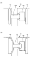
次いで、図5乃至図7を参照しながら、第1補助ヨーク凸部22Bと第1補助ヨーク凹部22Cとの係合について説明する。図5(a)に示すように、第1補助ヨーク凸部22Bを第1補助ヨーク凹部22Cへと挿入する。なお、図6に示すように、第1補助ヨーク凸部22Bの長さt2(長辺221が延びる方向の距離)は、第1補助ヨーク凹部22Cの同方向の長さt1よりも若干大きくなるように構成されている。このため、第1補助ヨーク凸部22Bの先端部分が、第1補助ヨーク凹部22Cの底辺部に当接した状態では、図5(b)に示すように、一方の短辺222と他方の短辺222との間には、若干の間隙Kが形成されることとなる。この間隙Kの幅Δtは、Δt2-Δt1となっている。そして、図6に示すように、挿入部223の軸方向距離t3と、第1補助ヨーク凸部22Bの軸方向距離t4とほぼ同等となるように構成されている(長さt3≒長さt4)。このように構成されているため、この図5(b)に示す状態では、挿入部223に第1補助ヨーク凸部22Bに基端部側が保持されることとなるが、本実施形態では、第1補助ヨーク凸部22Bを第1補助ヨーク凹部22Cに対し、より強く係合するために、図5(b)の状態から更に矢印方向に力を加える。もちろん、第1補助ヨーク凸部22Bを挿入部223に挿入し易くする観点から、挿入部223の軸方向距離t3を第1補助ヨーク凸部22Bの軸方向距離t4よりも若干大きくしてもよい。
Next, the engagement between the first auxiliary yoke
このように、図5(b)の状態から、矢印方向に力を加えると、間隙Kの幅がほぼ0となり、一方の短辺222と他方の短辺222とが当接(圧接含む)若しくは近接することとなる。そして、同時に、第1補助ヨーク凸部22Bの先端部分が、第1補助ヨーク凹部22Cに圧接し、図5(c)に示すように第1補助ヨーク凸部22Bの先端部が第1補助ヨーク凹部22Cの変形部224内部で変形する。このとき、変形部224の軸方向距離t5は、第1補助ヨーク凸部22Bの軸方向距離t4よりも大きくなるように構成されているため、この差分が変形代となって、第1補助ヨーク凸部22Bの先端が第1補助ヨーク凹部22C内で変形する。換言すれば、第1補助ヨーク凸部22Bの先端が押し潰される。このとき、第1補助ヨーク凸部22Bの先端部に形成された吸収孔H1が変形することにより、第1補助ヨーク凸部22Bが、加えられる力で破損することを有効に防止することができる。
In this way, when a force is applied in the direction of the arrow from the state of FIG. 5B, the width of the gap K becomes almost zero, and one
以上のように、本実施形態においては、変形部224内で第1補助ヨーク凸部22Bの先端部分が軸方向に押し拡げられるように潰れ、これにより、第1補助ヨーク凸部22Bの先端部分の軸方向距離が挿入部223の軸方向距離t3よりも大きくなる。換言すると、第1補助ヨーク凸部22Bの先端部には、当該先端部分が潰れることで軸方向距離が長くなるように拡がった拡がり部226が設けられるようになる。この拡がり部226の軸方向両端が、図5(c)に示すように、変形部224の軸方向両端に位置する縁面に圧接することで第1補助ヨーク凸部22Bが第1補助ヨーク凹部22Cに係合する。これにより、第1補助ヨーク凸部22Bを第1補助ヨーク凹部22Cに確実かつ高い強度で係合することが可能となる。以上のように、第1補助ヨーク凸部22Bの先端が変形部224内に圧接することにより、第1補助ヨーク凸部22Bが挿入部223から抜けるのを有効に防止することができる。
As described above, in the present embodiment, the distal end portion of the first auxiliary yoke
以上までに説明してきたように、本開示の第1実施形態によれば、第1補助ヨーク22がメインヨーク21の外側面の周方向に沿って当該外側面に配置された状態で、第1補助ヨーク凸部22Bが第1補助ヨーク凹部22Cと対向して係合している。この結果、メインヨーク21に影響を与えることなく(具体的には、内径変形を生じずに)メインヨーク21の外側面に第1補助ヨーク22を巻き付けることが可能となる。また、メインヨーク21や第1補助ヨーク22の内外径の精度要求を低減することができるとともに、メインヨーク21の外側面におけるメッキ剥がれや加工油溜まり等の問題が発生するのを抑えることが可能となる。なお、上記の係合構造は、メインヨーク21の内側面に沿って第1補助ヨーク22を配置する構成においても同様であり、かかる構成では、メインヨーク21の内側面よりも径方向中心側で第1補助ヨーク凸部22Bを第1補助ヨーク凹部22Cに係合させることになる。
As described above, according to the first embodiment of the present disclosure, the first
また、図5(c)のように、第1補助ヨーク凸部22Bの先端部に設けられた拡がり部226の軸方向両端が変形部224の軸方向両端に位置する縁面に圧接する場合、その間に生じる摩擦力のみで係合状態を保持することになる。これに対し、図7に示すように、拡がり部226において第1補助ヨーク凸部22Bの基端部側に位置する表面が、第1補助ヨーク凹部22Cにおける段差225に密接(密着)するように第1補助ヨーク凸部22Bが第1補助ヨーク凹部22Cに係合すれば、その係合状態がより強固に保持されるようになる。
Further, as shown in FIG. 5C, when both axial ends of the expanded
<第1ステータの製造方法について>
次いで、図8により、本実施形態に係る第1ステータ2の製造方法について説明する。上記説明及び図8(a)に示すように、第1補助ヨーク22は、当初、長方形の帯状板体で構成されており、一方の短辺には、3個の第1補助ヨーク凸部22Bが形成されるとともに、他方の短辺には、3個の第1補助ヨーク凹部22Cが形成されている。そして、図8(b)に示す配置工程では、この帯状の第1補助ヨーク22の第1補助ヨーク本体部22Aをメインヨーク本体部21Bの外側面に巻き付ける。このとき、第1補助ヨーク凸部22Bと第1補助ヨーク凹部22Cとが周方向に突き合うように巻き付ける。次いで、図8(b)の矢印で示すように、挿入工程において、第1補助ヨーク凸部22Bを第1補助ヨーク凹部22Cに挿入する(図5(a)も参照)。次いで、図8(c)に示す圧接工程では、周方向への力Fを更に加え、第1補助ヨーク凸部22Bの先端を、第1補助ヨーク凹部22Cの変形部224の内縁に押し当てて、当該第1補助ヨーク凸部22Bの先端部を変形させる。そして、最終的には、第1補助ヨーク凸部22Bの先端部分が、第1補助ヨーク凹部22Cの変形部224内部で変形して(換言すると、拡がり部226を形成して)、変形部224の軸方向両端の縁面に圧接するようになる。これにより、第1補助ヨーク凸部22Bが第1補助ヨーク凹部22Cに確実かつ高い強度で係合される(図5(b)→図5(c)も参照)。このようにして、メインヨーク21に第1補助ヨーク22が組付けられる。このとき、拡がり部226において第1補助ヨーク凸部22Bの基端部側に位置する表面が、挿入部223と変形部224との間の段差225に密接(密着)していれば、第1補助ヨーク凸部22Bと第1補助ヨーク凹部22Cとの係合状態を更に強固に保持することが可能となる。
<About the manufacturing method of the first stator>
Next, a method for manufacturing the
なお、第1ステータ2を形成するにあたり、マグネット23を配置する工程も実施されるが、この工程は、どの段階で行われてもよい。好ましくは、第1補助ヨーク凸部22Bと第1補助ヨーク凹部22Cとの係合位置を把握しやすいように、第1補助ヨーク22をメインヨーク本体部21Bに巻設する前の段階で配置するとよい。また、本実施形態においては、第1補助ヨーク22をメインヨーク本体部21Bの外側面に巻設する構成としたため、マグネット23は、メインヨーク本体部21Bの内側面に配設されるが、この配設方法としては、接着剤での接着、溶接等、どのような方法で実行されてもよい。
In addition, when forming the
<第1ステータの製造方法のバリエーション>
次いで、図9により、本実施形態に係る第1ステータ2の製造方法に関するバリエーションについて説明する。なお、図9の(c)~(e)に図示の工程は、後述する2つの分割金型S1,S2を用いて行われるが、図9の(c)~(e)では説明の都合上、分割金型S1,S2の図示を省略している。また、図9の(c)~(e)には、第1補助ヨーク22の取付部分の拡大図を併せて図示している。バリエーションに係る第1ステータ2の製造方法では、図9(a)に示すように、上下に二分割された成形用金型(分割金型S1,S2)の間にメインヨーク21及び第1補助ヨーク22を挟み込みながら両ヨークを径方向に加圧することでメインヨーク21の外側面に第1補助ヨーク22を配置する。より詳しく説明すると、配置工程において、帯状の第1補助ヨーク22の第1補助ヨーク本体部22Aをメインヨーク本体部21Bの外側面に巻き付ける。その後、図9(b)に示すように、第1補助ヨーク22が巻き付けられたメインヨーク21を、2つの分割金型S1,S2の間に形成される略円柱状の収容空間内に収容する。そして、メインヨーク21及び第1補助ヨーク22を収容空間内に収容したままの状態で、2つの分割金型S1,S2によって両ヨークを挟み込みながら径方向に加圧して挿入工程及び圧接工程を行う。これにより、図9(c)に示すように、第1補助ヨーク凸部22Bの先端部が挿入部223を通じて第1補助ヨーク凹部22C内に挿入され、変形部224に圧接して変形し、拡がり部226を形成する。その後、さらにメインヨーク21及び第1補助ヨーク22を径方向に加圧すると、図9(d)に示すように、両ヨークが縮径すると共に、第1補助ヨーク凸部22Bの先端部が更に押し潰れて変形部224の軸方向距離に相当する長さまで拡がり部226が拡がる。以上の工程を経ると、メインヨーク21が元の径まで復元しようとする一方で、第1補助ヨーク22は、メインヨーク21からの押圧に抗して縮径状態を維持しようとする。このため、第1補助ヨーク凸部22Bには第1補助ヨーク凹部22Cから抜けようとする力が作用する。このとき、図9(e)に示すように、拡がり部226が挿入部223及び変形部224の間の段差225によって係止される。これにより、第1補助ヨーク凸部22Bと第1補助ヨーク凹部22Cとの係合状態が強固に保持されるようになる。
<Variation of first stator manufacturing method>
Next, referring to FIG. 9, variations regarding the method for manufacturing the
<<第2実施形態>>
次いで、図10乃至図12により、第2実施形態について説明する。本例に係る第2ステータ102は、上記第1実施形態に比して、第1補助ヨーク22の形状が、第2補助ヨーク6に変更されたもので、他は同様である。第2補助ヨーク6は、図10に示したように、第2補助ヨーク本体部6Aと、回動かしめ部6Bと、を備えて構成されている。第2補助ヨーク本体部6Aは、長方形状(帯状)の板体であり、環状に丸めることにより円筒形状となる部分である。なお、以下、説明のため、長方形状の第2補助ヨーク本体部6Aの長辺を「長辺106」と記し、短辺を「短辺206」と記す。この長辺106は、メインヨーク本体部21Bの外面の胴回りの長さよりも若干短くなるように構成されている。
<< Second Embodiment >>
Next, a second embodiment will be described with reference to FIGS. The
回動かしめ部6Bは、図10に示すように、作用部61と、一方連結部62と、他方連結部63と、を有して構成されている。作用部61は、矩形平板状に形成されており、この外周の一点である一方点P1から一方の短辺206へと亘るように一方連結部62が延びており、この外周の一点である他方点P2から他方の短辺206へと亘るように他方連結部63が延びている。なお、この一方点P1と他方点P2は、作用部61の中心に対して点対称の位置に形成される。このように構成されているため、作用部61に黒矢印方向の回転力を加えると、第2補助ヨーク本体部6Aの短辺206,206の周方向距離が縮まることとなる。
As shown in FIG. 10, the
つまり、図11に示すように、作用部61に黒矢印方向の回転力を加えると、第2補助ヨーク本体部6Aの短辺206,206の周方向距離が、t6からt7に縮まることとなる。よって、初期状態において、第2補助ヨーク6の内周を、(t6-t7)分、メインヨーク本体部21Bの外周よりも大きく形成しておき、初期状態の第2補助ヨーク6に、メインヨーク本体部21Bを挿入し、作用部61に黒矢印方向の回転力を加えることで、メインヨーク本体部21Bの外周に第2補助ヨーク6を取付けることができる。なお、図12に、模式的に回動かしめ部6Bの機能を示した。図12の(a)→(b)→(c)のルートでは、上記のように、第2補助ヨーク本体部6Aの短辺206,206の周方向距離が、t6からt7に縮まるが、作用部61に対して反対方向の回転力を加えることにより、第2補助ヨーク本体部6Aの短辺206,206の周方向距離を、t6からt8に広げることもできる。このように、本例では、第2補助ヨーク6が着脱可能となるとともに、微調整もまた容易に行うことができる。
That is, as shown in FIG. 11, when a rotational force in the direction of the black arrow is applied to the
更に、この第2補助ヨーク6をメインヨーク本体部21Bの内周面に装着する場合には、第2補助ヨーク本体部6Aの短辺206,206の周方向距離を、t6からt8に広げるとよい。これは、図12の(a)→(d)→(e)のルートである。つまり、初期状態において、第2補助ヨーク6の内周を、(t8-t6)分、メインヨーク本体部21Bの内周よりも小さく形成しておき、初期状態の第2補助ヨーク6を、メインヨーク本体部21Bに挿入し、作用部61に図12(d)の黒矢印方向の回転力を加えることで、メインヨーク本体部21Bの内周に第2補助ヨーク6を取付けることができる。
Further, when the second
また、当該回動かしめ部6Bもまた、上記第1実施形態と同様の理由で、マグネット23が配置されている位置の外側に配置されるように構成されていると好適である。更に、第2ステータ102の製造方法としては、以下のようになる。まず、初期状態の第2補助ヨーク6(短辺206,206が回動かしめ部6Bで連結されて円筒形状となっている状態である)に、メインヨーク本体部21Bを挿入する(若しくは、メインヨーク本体部21Bに第2補助ヨーク6を挿入する)配置工程を行う。次いで、作用部61を回動させて、第2補助ヨーク本体部6Aの短辺206,206の周方向距離を縮める(若しくは引き離す)ことにより、第2補助ヨーク6をメインヨーク本体部21Bの外周壁面(若しくは内周壁面)に圧接させる圧接工程を行う。なお、第2ステータ102を形成するにあたり、マグネット23を配置する工程等は、上記第1実施形態と同様であるため、説明は省略する。
Further, it is preferable that the
<<分割コア型ステータの製造方法>>
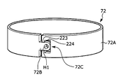
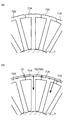
次に、上述したステータ製造方法の応用例として、分割コア型ステータ7の製造方法について図13乃至図17を参照しながら説明する。図13は、分割コア型ステータ7の模式平面図、図14は、巻きヨーク72の斜視図、図15は、分割コア型ステータ7の製造工程を示す説明図、図16及び図17は、巻きヨーク72のバリエーションを示す図である。なお、図14には、分割コア71の外側面に巻き付けられた状態の巻きヨーク72を図示しているが、図示の都合上、同図では分割コア71の図示を省略している。
<< Production Method of Split Core Type Stator >>
Next, as an application example of the above-described stator manufacturing method, a method of manufacturing the split
分割コア型ステータ7は、図13に示すように、円環状の分割コア71と、巻きヨーク72と、を有して構成されている。分割コア71は、略T字状のコア片71Aを周方向に沿って環状に並べて構成されている。巻きヨーク72は、分割コア71の外側面周りに配置された円環状の金属板である。比較例として、分割コア型ステータ7は、コア片71Aを周方向に沿って環状に並べて分割コア71を仮組みした後、予め円筒状に成形された巻きヨーク72を仮組みした分割コア71に対して圧入することで構成できる。しかしながら、このような手順では、仮組みした分割コア71に対して巻きヨーク72を圧入する際に分割コア71が崩れてしまう(厳密には、コア片71Aの連結状態が解けてしまう)虞がある。これに対して、上述した第1補助ヨーク22や第2補助ヨーク6と同様の構造を巻きヨーク72に採用すれば、仮組みした分割コア71の外側面に巻きヨーク72を無理なく組み付けることができ、分割コア型ステータ7を容易に組み立てることが可能となる。
As shown in FIG. 13, the split
具体的に説明すると、第1補助ヨーク22と同じ構造の巻きヨーク72を用いる場合、当該巻きヨーク72は、図14に示すように、帯状の巻きヨーク本体部72Aを有するとともに、その一端部に凸部72Bを、その他端部に凹部72Cを有する。巻きヨーク本体部72Aは、上述の第1補助ヨーク本体部22Aと同様の構造であり、その長辺は、分割コア71の外側面の周長(周方向における長さ)と略同じ長さとなるように構成されている。また、凸部72Bは、上述の第1補助ヨーク凸部22Bと同様の構造であり、凹部72Cは、上述の第1補助ヨーク凹部22Cと同様の構造である。
More specifically, when the winding
以上のような構成の巻きヨーク72であれば、第1実施形態において第1補助ヨーク22をメインヨーク21の外側面に配置した手順と略同じ手順にて分割コア71の外側面に配置することができる。より詳しく説明すると、先ず、図15(a)に示すように、コア片71Aを周方向に沿って環状に並べて分割コア71を仮組みする。このとき、コア中心(コア片71Aの内側面に接する位置)に円柱状の治具Tを配置し、この治具Tの外周面周りにコア片71Aを配置すれば、コア片71Aを円環状に容易に配置することが可能となる。その後、図15(b)に示すように、巻きヨーク72の巻きヨーク本体部72Aを仮組みされた分割コア71の外側面に巻き付ける。このとき、コア中心に上述の治具Tを配置し続けることで、分割コア71の真円度を良好に保ちながら巻きヨーク72を巻き付けることができる。
In the case of the winding
巻きヨーク72を分割コア71の外側面に巻き付けると、凸部72Bと凹部72Cとが周方向に突き合うようになる。かかる状態となった上で挿入工程を行い、当該工程において巻きヨーク72を径方向中心側に引っ張って凸部72Bを凹部72Cに挿入する。これにより、図5(a)に図示の手順と同じ手順にて、凸部72Bの先端部が凹部72Cの挿入部223を通って変形部224まで進入する。その後、圧接工程を行い、図5(b)に図示の手順と同じ手順にて、凸部72Bの先端を凹部72Cの変形部224の内縁に押し当てて、当該凸部72Bの先端部を押し潰す。これにより、図5(c)に図示した状況と同様、凸部72Bの先端部が凹部72Cの変形部224内で変形して拡がり部226を形成し、変形部224の軸方向両端の縁面に圧接するようになる。これにより、凸部72Bが凹部72Cに確実かつ高い強度で係合される。このようにして巻きヨーク72が分割コア71に組み付けられる。なお、圧縮工程では、巻きヨーク本体部72Aが径方向中心側に引っ張られるため、巻きヨーク本体部72Aの内側に位置するコア片71Aが径方向中心側に押圧される。これにより、各コア片71Aが円柱状の治具Tの外周面に押し付けられ、結果として分割コア71の真円度を更に向上させることが可能になる。
When the winding
ところで、凸部72B及び凹部72Cの各々の形状については、第1実施形態における第1補助ヨーク凸部22B及び第1補助ヨーク凹部22Cと同様の形状に限定されるものではなく、他の形状も考えられる。一例を挙げて説明すると、図16に示すように、凸部72B及び凹部72Cがスナップフィット形式にて係合することができる構造であってもよい。つまり、図16の(a)に示すように、凸部72Bの先端部における軸方向両端部が爪状に突出しており、凹部72Cの挿入部223が凸部72Bの先端形状に対応してテーパ形状をなしていてもよい。このような構成において、巻きヨーク72を径方向中心側に引っ張って凸部72Bを凹部72Cに挿入すると、図16の(b)に示すように、凸部72Bの先端部が凹部72Cの挿入部223を押し拡げながら凹部72Cの変形部224まで進入した後に、押し拡げられていた挿入部223が元のサイズに戻る。これにより、凸部72Bが凹部72Cとスナップフィット形式にて係合するようになる。
By the way, the shape of each of the
また、巻きヨーク72を分割コア71に組み付ける方法としては、帯状の巻きヨーク本体部72Aを分割コア71の外側面に巻き付けるものに限定されず、図17に図示した方法を利用してもよい。図17に図示の方法では、予め円筒状に丸められた巻きヨーク本体部72A内に分割コア71を挿入(厳密には、緩挿)してから、巻きヨーク本体部72Aの内径を分割コア71の外側面の径まで縮径させて巻きヨーク72を分割コア71に組み付ける。
Further, the method of assembling the winding
より詳しく説明すると、図17に図示の方法において、巻きヨーク72は、図17の(a)に示すように、円筒状の巻きヨーク本体部72Aの周方向中途位置に途切れ部72Gを有するとともに、この途切れ部に第1延出部72D、第2延出部72E及び中央連結部72Fを備える。第1延出部72Dは、途切れ部72Gの周方向一端から他端に向かって延出した矩形状の部分である。第2延出部72Eは、途切れ部72Gの周方向他端から一端に向かって延出した矩形状の部分である。第1延出部72D及び第2延出部72Eは、対称的に配置されており、軸方向においては互いに離れており、周方向において一部分が重なる位置にある。また、第1延出部72Dの先端と途切れ部72Gの周方向他端との間、及び、第2延出部72Eの先端と途切れ部72Gの周方向一端には、それぞれ隙間Qが形成されている。これら2つの隙間Qの幅(周方向における長さ)は、互いに同じ長さとなっている。そして、巻きヨーク72を分割コア71に取り付ける際には、図17の(b)に示すように、巻きヨーク本体部72Aの内径を上記の隙間Qに応じた分だけ縮ませることになる。つまり、隙間Qが消滅することで途切れ部72Gの周方向長さが短くなり、その分、巻きヨーク本体部72Aの内径が縮むようになる。
More specifically, in the method shown in FIG. 17, the winding
中央連結部72Fは、軸方向において第1延出部72Dと第2延出部72Eとの間に介在し、軸方向に長く延びている。この中央連結部72Fは、巻きヨーク72を分割コア71に組み付ける前の時点では、図17の(a)に示すように側方視で略長方形状をなしている。一方で、巻きヨーク72を分割コア71に組み付けるために巻きヨーク本体部72Aを縮径させると、図17の(b)に示すように、中央連結部72Fの軸方向一端側の辺が他端側の辺に対してズレるように中央連結部72Fが変形する(歪む)。換言すると、巻きヨーク本体部72Aは、中央連結部72Fが図17の(a)に図示した状態から(b)に図示した状態へと変形することで上述の隙間Qに応じた分だけ縮径する。以上のような構造の巻きヨーク72によれば、仮組み状態の分割コア71に対して無理なく(分割コア71を崩すことなく)組み付けることが可能となる。
The central connecting
本開示は実施例を参照して記載されているが、本開示は開示された上記実施例や構造に限定されるものではないと理解される。寧ろ、本開示は、様々な変形例や均等範囲内の変形を包含する。加えて、本開示の様々な要素が、様々な組み合わせや形態によって示されているが、それら要素よりも多くの要素、あるいは少ない要素、またはそのうちの1つだけの要素を含む他の組み合わせや形態も、本開示の範疇や思想範囲に入るものである。 Although the present disclosure has been described with reference to embodiments, it is understood that the present disclosure is not limited to the above-described embodiments and structures. Rather, the present disclosure includes various modifications and modifications within the equivalent scope. In addition, although various elements of the present disclosure have been shown in various combinations and forms, other combinations or forms that include more or fewer elements than those elements, or only one of them. Are within the scope and spirit of the present disclosure.
Claims (13)
該ステータは、
有底筒状のメインヨーク(21)と、
該メインヨークの外周壁面若しくは内周壁面に配置された帯状の補助ヨーク(22)と、
前記メインヨークの内部において、前記電機子の外側面と径方向に対向するように配置された界磁用マグネット(23)と、を備えて構成され、
前記補助ヨークは、前記メインヨークの外周壁面若しくは内周壁面の周方向に沿って配置されており、
前記補助ヨークの一端部には、少なくとも1個の凸部(22B、72B)が形成され、
前記補助ヨークの他端部には、前記補助ヨークが前記周方向に沿って前記メインヨークの外周壁面若しくは内周壁面に配置された状態で前記周方向において前記凸部と対向して係合している少なくとも1個の凹部(22C、72C)が形成されていることを特徴とするステータ。 A bottomed cylindrical stator that constitutes a rotating electrical machine and stores an armature fixed to a rotating shaft,
The stator is
A bottomed cylindrical main yoke (21);
A belt-like auxiliary yoke (22) disposed on the outer peripheral wall surface or the inner peripheral wall surface of the main yoke;
A magnetic field magnet (23) disposed to face the outer surface of the armature in the radial direction inside the main yoke;
The auxiliary yoke is disposed along the circumferential direction of the outer peripheral wall surface or inner peripheral wall surface of the main yoke,
At least one convex portion (22B, 72B) is formed at one end of the auxiliary yoke,
The other end portion of the auxiliary yoke is engaged with the auxiliary yoke so as to face the convex portion in the circumferential direction in a state where the auxiliary yoke is disposed on the outer peripheral wall surface or the inner peripheral wall surface of the main yoke along the circumferential direction. And at least one recess (22C, 72C) formed therein.
前記第1孔部の軸方向距離は、前記第2孔部の軸方向距離よりも小さく、
前記凸部の先端部には、前記凸部の先端部が押し潰れて軸方向距離が長くなるように拡がった拡がり部(226)が設けられており、
前記凸部は、前記拡がり部において前記凸部の基端部側に位置する表面が前記第1孔部と前記第2孔部との間に形成された段差に密接した状態で前記凹部に係合していることを特徴とする請求項2に記載のステータ。 The recess includes a first hole (223) that is closer to the opening of the recess, and a second hole (224) that is further away from the opening than the first hole and communicates with the first hole. Have
The axial distance of the first hole is smaller than the axial distance of the second hole,
The front end of the convex portion is provided with an expanded portion (226) that is expanded so that the front end portion of the convex portion is crushed and the axial distance is increased,
The convex portion is engaged with the concave portion in a state in which a surface of the expanded portion located on the base end side of the convex portion is in close contact with a step formed between the first hole portion and the second hole portion. The stator according to claim 2, wherein the stator is aligned.
前記凸部の先端部側は、前記凹部の内部に配置されるとともに、前記凸部の先端は、前記凹部の内部を規定する周縁部の一部に圧接しており、
前記凸部の基端部側は、前記凸部の先端部側よりも軸方向距離が小さくなるように構成されるとともに、前記凹部の開口部に配置されていることを特徴とする請求項1乃至請求項3のいずれか一項に記載のステータ。 The axial distance of the opening of the recess is formed to be smaller than the internal axial distance,
The front end side of the convex portion is disposed inside the concave portion, and the front end of the convex portion is in pressure contact with a part of the peripheral edge that defines the inside of the concave portion,
The base end side of the convex portion is configured to have a smaller axial distance than the distal end side of the convex portion, and is disposed in the opening of the concave portion. The stator according to any one of claims 3 to 4.
該ステータは、
有底筒状のメインヨーク(21)と、
該メインヨークの外周壁面若しくは内周壁面に配置され、帯状の板体である補助ヨーク本体部の一端部と他端部とが連絡されて筒状となった補助ヨーク(6)と、
前記メインヨークの内部において、前記電機子の外側面と径方向に対向するように配置された界磁用マグネット(23)と、を備えて構成され、
前記補助ヨークは、前記メインヨークの外周壁面若しくは内周壁面の周方向に沿って配置されており、
前記補助ヨーク本体部の一端部と他端部とは、一方側を他方側へと引き寄せる若しくは引き離すように回動可能な回動かしめ部(6B)を介して周方向に連結されており、
前記補助ヨークは、前記メインヨークの内周壁面若しくは外周壁面に圧接していることを特徴とするステータ。 A bottomed cylindrical stator that constitutes a rotating electrical machine and stores an armature fixed to a rotating shaft,
The stator is
A bottomed cylindrical main yoke (21);
An auxiliary yoke (6) disposed on the outer peripheral wall surface or the inner peripheral wall surface of the main yoke and having a cylindrical shape by connecting one end portion and the other end portion of the auxiliary yoke main body which is a belt-like plate body;
A magnetic field magnet (23) disposed to face the outer surface of the armature in the radial direction inside the main yoke;
The auxiliary yoke is disposed along the circumferential direction of the outer peripheral wall surface or inner peripheral wall surface of the main yoke,
One end and the other end of the auxiliary yoke main body are connected in the circumferential direction via a swaging caulking portion (6B) that can be pivoted so as to draw one side toward or away from the other.
The stator, wherein the auxiliary yoke is in pressure contact with an inner peripheral wall surface or an outer peripheral wall surface of the main yoke.
平板状の作用部と、
該作用部の一方点(P1)と前記補助ヨーク本体部の一端部とを連結する一方側連結部と、
前記作用部の他方点(P2)と前記補助ヨーク本体部の他端部とを連結する他方側連結部と、を備え、
前記他方点は、前記作用部の中心に対して、前記一方点と点対称の位置に形成されることを特徴とする請求項6に記載のステータ。 The rotating caulking portion is
A plate-like working part;
A one-side connecting part that connects one point (P1) of the working part and one end of the auxiliary yoke body part;
The other side connection part that connects the other point (P2) of the action part and the other end part of the auxiliary yoke body part,
The stator according to claim 6, wherein the other point is formed at a point-symmetrical position with respect to the one point with respect to the center of the action portion.
一端部に少なくとも1個の凸部(22B、72B)が形成されるとともに、他端部に前記凸部と係合する少なくとも1個の凹部(22C、72C)が形成された帯状の補助ヨークを、前記メインヨークの外周壁面若しくは内周壁面に沿わせながら、前記メインヨークの外周壁面及び内周壁面の周方向に沿って前記凸部と前記凹部とが突き合うように丸める配置工程と、
前記凹部に対し、前記凸部を挿入する挿入工程と、
前記凹部の一部である周端部に前記凸部の先端部を圧接させて前記凸部を変形させることにより、前記凹部に前記凸部を係合させる圧接工程と、を行うことを特徴とするステータの製造方法。 A bottomed cylindrical main yoke (21), a belt-like auxiliary yoke (22) disposed on the outer peripheral wall surface or inner peripheral wall surface of the main yoke, and the outer surface of the armature and the radial direction inside the main yoke A field magnet (23) disposed to face the magnetic field, and a method of manufacturing a stator for storing the armature fixed to a rotating shaft,
A belt-shaped auxiliary yoke having at least one convex portion (22B, 72B) formed at one end and at least one concave portion (22C, 72C) engaged with the convex portion at the other end is provided. An arrangement step in which the convex portion and the concave portion are rounded so as to abut along the circumferential direction of the outer peripheral wall surface and the inner peripheral wall surface of the main yoke while being along the outer peripheral wall surface or the inner peripheral wall surface of the main yoke;
An insertion step of inserting the convex portion with respect to the concave portion;
A pressure contact step of engaging the convex portion with the concave portion by deforming the convex portion by pressing the distal end portion of the convex portion with a peripheral end portion that is a part of the concave portion. A method for manufacturing a stator.
前記収容空間内の前記メインヨーク及び前記補助ヨークを、前記2つの分割金型によって挟み込んで前記メインヨークの径方向に加圧することで、前記凹部に対して前記凸部を挿入して前記凹部に前記凸部を係合させることを特徴とする請求項10に記載のステータの製造方法。 In the insertion step and the pressure contact step, the main yoke and the auxiliary yoke wound around the outer peripheral wall surface of the main yoke are accommodated in an accommodation space formed between the two split molds (S1, S2). Done in state
The main yoke and the auxiliary yoke in the housing space are sandwiched between the two split molds and pressed in the radial direction of the main yoke, so that the convex portion is inserted into the concave portion to the concave portion. The method for manufacturing a stator according to claim 10, wherein the convex portions are engaged.
前記圧接工程では、前記吸収孔を変形させることにより、前記凹部内で前記凸部の先端部分を変形させて前記凹部に前記凸部を係合することを特徴とする請求項10又は請求項11に記載のステータの製造方法。 An absorption hole (H1) is formed in the convex portion,
12. In the press-contacting step, by deforming the absorption hole, the tip portion of the convex portion is deformed in the concave portion, and the convex portion is engaged with the concave portion. A method for manufacturing the stator according to claim 1.
帯状の板体である補助ヨーク本体部の一端部と他端部とを連絡するとともに、回動することにより一方側を他方側へと引き寄せる若しくは引き離す回動かしめ部(6B)によって連結されて筒状となった前記補助ヨークを、前記メインヨークの外周壁面若しくは内周壁面に装着する配置工程と、
前記回動かしめ部を回動させて、前記補助ヨーク本体部の端部の一方側を他方側へと引き寄せる若しくは引き離すことにより、前記補助ヨークを前記メインヨークの外周壁面若しくは内周壁面に圧接させる圧接工程と、を行うことを特徴とするステータの製造方法。 A bottomed cylindrical main yoke (21), an auxiliary yoke (6) disposed on an outer peripheral wall surface or an inner peripheral wall surface of the main yoke, and an outer surface of the armature in a radial direction inside the main yoke. A field magnet (23) arranged so as to make a stator that houses the armature fixed to the rotating shaft,
A tube is connected by a rotating caulking portion (6B) that connects one end portion and the other end portion of the auxiliary yoke main body, which is a belt-like plate body, and pulls one side toward or away from the other by rotating. A mounting step of mounting the auxiliary yoke on the outer peripheral wall surface or inner peripheral wall surface of the main yoke;
By rotating the swaging caulking portion and pulling one side of the end portion of the auxiliary yoke main body portion toward or away from the other side, the auxiliary yoke is pressed against the outer peripheral wall surface or inner peripheral wall surface of the main yoke. A method of manufacturing a stator, comprising: performing a pressure welding process.
Priority Applications (5)
| Application Number | Priority Date | Filing Date | Title |
|---|---|---|---|
| DE112017004346.8T DE112017004346T5 (en) | 2016-08-30 | 2017-08-24 | STATOR AND MANUFACTURING PROCESS OF A STATOR |
| CN201780052383.9A CN109690916B (en) | 2016-08-30 | 2017-08-24 | Stator and method of making the same |
| CN202110195121.6A CN113014005B (en) | 2016-08-30 | 2017-08-24 | Stator and method for manufacturing same |
| US16/275,804 US11011947B2 (en) | 2016-08-30 | 2019-02-14 | Stator and manufacturing method of stator |
| US17/213,438 US11990792B2 (en) | 2016-08-30 | 2021-03-26 | Stator with split core and yoke with protrusions and recesses engaging together and surrounding the split core |
Applications Claiming Priority (4)
| Application Number | Priority Date | Filing Date | Title |
|---|---|---|---|
| JP2016-167804 | 2016-08-30 | ||
| JP2016167804 | 2016-08-30 | ||
| JP2017110944A JP6915391B2 (en) | 2016-08-30 | 2017-06-05 | Stator and its manufacturing method |
| JP2017-110944 | 2017-06-05 |
Related Child Applications (1)
| Application Number | Title | Priority Date | Filing Date |
|---|---|---|---|
| US16/275,804 Continuation US11011947B2 (en) | 2016-08-30 | 2019-02-14 | Stator and manufacturing method of stator |
Publications (1)
| Publication Number | Publication Date |
|---|---|
| WO2018043263A1 true WO2018043263A1 (en) | 2018-03-08 |
Family
ID=61301496
Family Applications (1)
| Application Number | Title | Priority Date | Filing Date |
|---|---|---|---|
| PCT/JP2017/030221 Ceased WO2018043263A1 (en) | 2016-08-30 | 2017-08-24 | Stator and manufacturing method therefor |
Country Status (2)
| Country | Link |
|---|---|
| CN (1) | CN113014005B (en) |
| WO (1) | WO2018043263A1 (en) |
Cited By (1)
| Publication number | Priority date | Publication date | Assignee | Title |
|---|---|---|---|---|
| JP2019193345A (en) * | 2018-04-19 | 2019-10-31 | 株式会社デンソー | Rotary electric machine and manufacturing method of rotary electric machine |
Citations (5)
| Publication number | Priority date | Publication date | Assignee | Title |
|---|---|---|---|---|
| JPS5390906U (en) * | 1976-12-27 | 1978-07-25 | ||
| JPS5774656U (en) * | 1980-10-27 | 1982-05-08 | ||
| JPH04251540A (en) * | 1990-12-29 | 1992-09-07 | Nagano Nippon Densan Kk | Spindle motor |
| JPH0631354U (en) * | 1992-09-17 | 1994-04-22 | 株式会社安川電機 | DC motor frame structure |
| JP2005291367A (en) * | 2004-03-31 | 2005-10-20 | Nhk Spring Co Ltd | Boot ring |
Family Cites Families (5)
| Publication number | Priority date | Publication date | Assignee | Title |
|---|---|---|---|---|
| JP3704029B2 (en) * | 2000-07-24 | 2005-10-05 | 三菱電機株式会社 | Starting motor stator |
| JP3520035B2 (en) * | 2000-07-27 | 2004-04-19 | 三菱電機株式会社 | Stator of starting motor |
| US7038343B2 (en) * | 2002-02-22 | 2006-05-02 | Black & Decker Inc. | Field assembly for a motor and method of making same |
| JP2010104160A (en) * | 2008-10-24 | 2010-05-06 | Panasonic Corp | Dual rotor motor and manufacturing method therefor |
| JP2015100202A (en) * | 2013-11-19 | 2015-05-28 | 日本電産サンキョー株式会社 | Rotor, motor and method for manufacturing rotor |
-
2017
- 2017-08-24 WO PCT/JP2017/030221 patent/WO2018043263A1/en not_active Ceased
- 2017-08-24 CN CN202110195121.6A patent/CN113014005B/en active Active
Patent Citations (5)
| Publication number | Priority date | Publication date | Assignee | Title |
|---|---|---|---|---|
| JPS5390906U (en) * | 1976-12-27 | 1978-07-25 | ||
| JPS5774656U (en) * | 1980-10-27 | 1982-05-08 | ||
| JPH04251540A (en) * | 1990-12-29 | 1992-09-07 | Nagano Nippon Densan Kk | Spindle motor |
| JPH0631354U (en) * | 1992-09-17 | 1994-04-22 | 株式会社安川電機 | DC motor frame structure |
| JP2005291367A (en) * | 2004-03-31 | 2005-10-20 | Nhk Spring Co Ltd | Boot ring |
Cited By (1)
| Publication number | Priority date | Publication date | Assignee | Title |
|---|---|---|---|---|
| JP2019193345A (en) * | 2018-04-19 | 2019-10-31 | 株式会社デンソー | Rotary electric machine and manufacturing method of rotary electric machine |
Also Published As
| Publication number | Publication date |
|---|---|
| CN113014005A (en) | 2021-06-22 |
| CN113014005B (en) | 2024-08-13 |
Similar Documents
| Publication | Publication Date | Title |
|---|---|---|
| CN103944291A (en) | Rotary electric machine | |
| US20020084709A1 (en) | Motor | |
| JP2007043845A (en) | Stator structure and method for manufacturing stator | |
| JP3958732B2 (en) | Rotating electric machine and manufacturing method thereof | |
| JP7168039B2 (en) | Stator and manufacturing method thereof | |
| WO2018043263A1 (en) | Stator and manufacturing method therefor | |
| JPH10248222A (en) | Ultra-small motor and manufacturing method thereof | |
| JP3003748B2 (en) | Method for manufacturing rotor of magnet generator | |
| JP3569463B2 (en) | motor | |
| EP1388922A2 (en) | Rotor, Manufacturing Method of the Rotor and Motor using the Rotor | |
| JP2003153483A (en) | Motor bracket mounting structure | |
| JP2001025221A (en) | Manufacturing method of small motor | |
| JP2000274494A (en) | Ring gear | |
| JP2017135967A (en) | Stator and manufacturing method of stator | |
| JP4180588B2 (en) | Vibration motor with internal weight and its manufacturing method | |
| JPH0266324A (en) | Electromagnetic clutch | |
| JP2006311657A (en) | Electric actuator | |
| JP7130728B2 (en) | ROTOR, BRUSHLESS MOTOR, ROTOR MANUFACTURING METHOD | |
| JP2000050597A (en) | Thin cylindrical coreless motor and battery-driven device using the same | |
| JPH11234932A (en) | Rotor structure of small motor | |
| JP7130726B2 (en) | ROTOR, BRUSHLESS MOTOR, ROTOR MANUFACTURING METHOD | |
| JP2004064832A (en) | Motor structure | |
| JP4066745B2 (en) | Stator core and housing fixing structure | |
| JP2019118224A (en) | Stator, motor, and stator manufacturing method | |
| JP2005210812A (en) | Motor and manufacturing method thereof |
Legal Events
| Date | Code | Title | Description |
|---|---|---|---|
| 121 | Ep: the epo has been informed by wipo that ep was designated in this application |
Ref document number: 17846268 Country of ref document: EP Kind code of ref document: A1 |
|
| 122 | Ep: pct application non-entry in european phase |
Ref document number: 17846268 Country of ref document: EP Kind code of ref document: A1 |