WO2018043348A1 - 水素ガスの製造方法、及び鋼の製造方法 - Google Patents
水素ガスの製造方法、及び鋼の製造方法 Download PDFInfo
- Publication number
- WO2018043348A1 WO2018043348A1 PCT/JP2017/030579 JP2017030579W WO2018043348A1 WO 2018043348 A1 WO2018043348 A1 WO 2018043348A1 JP 2017030579 W JP2017030579 W JP 2017030579W WO 2018043348 A1 WO2018043348 A1 WO 2018043348A1
- Authority
- WO
- WIPO (PCT)
- Prior art keywords
- water
- metal material
- hydrogen gas
- iron
- light
- Prior art date
- Legal status (The legal status is an assumption and is not a legal conclusion. Google has not performed a legal analysis and makes no representation as to the accuracy of the status listed.)
- Ceased
Links
Images


Classifications
-
- C—CHEMISTRY; METALLURGY
- C01—INORGANIC CHEMISTRY
- C01G—COMPOUNDS CONTAINING METALS NOT COVERED BY SUBCLASSES C01D OR C01F
- C01G49/00—Compounds of iron
- C01G49/02—Oxides; Hydroxides
-
- C—CHEMISTRY; METALLURGY
- C01—INORGANIC CHEMISTRY
- C01B—NON-METALLIC ELEMENTS; COMPOUNDS THEREOF; METALLOIDS OR COMPOUNDS THEREOF NOT COVERED BY SUBCLASS C01C
- C01B3/00—Hydrogen; Gaseous mixtures containing hydrogen; Separation of hydrogen from mixtures containing it; Purification of hydrogen; Reversible storage of hydrogen
- C01B3/02—Production of hydrogen; Production of gaseous mixtures containing hydrogen
- C01B3/06—Production of hydrogen; Production of gaseous mixtures containing hydrogen by reaction of inorganic compounds containing electro-positively bound hydrogen with inorganic reducing agents
- C01B3/08—Production of hydrogen; Production of gaseous mixtures containing hydrogen by reaction of inorganic compounds containing electro-positively bound hydrogen with inorganic reducing agents by reaction of inorganic compounds with metals
-
- B—PERFORMING OPERATIONS; TRANSPORTING
- B01—PHYSICAL OR CHEMICAL PROCESSES OR APPARATUS IN GENERAL
- B01J—CHEMICAL OR PHYSICAL PROCESSES, e.g. CATALYSIS OR COLLOID CHEMISTRY; THEIR RELEVANT APPARATUS
- B01J23/00—Catalysts comprising metals or metal oxides or hydroxides, not provided for in group B01J21/00
- B01J23/70—Catalysts comprising metals or metal oxides or hydroxides, not provided for in group B01J21/00 of the iron group metals or copper
- B01J23/74—Iron group metals
- B01J23/745—Iron
-
- B—PERFORMING OPERATIONS; TRANSPORTING
- B01—PHYSICAL OR CHEMICAL PROCESSES OR APPARATUS IN GENERAL
- B01J—CHEMICAL OR PHYSICAL PROCESSES, e.g. CATALYSIS OR COLLOID CHEMISTRY; THEIR RELEVANT APPARATUS
- B01J23/00—Catalysts comprising metals or metal oxides or hydroxides, not provided for in group B01J21/00
- B01J23/70—Catalysts comprising metals or metal oxides or hydroxides, not provided for in group B01J21/00 of the iron group metals or copper
- B01J23/76—Catalysts comprising metals or metal oxides or hydroxides, not provided for in group B01J21/00 of the iron group metals or copper combined with metals, oxides or hydroxides provided for in groups B01J23/02 - B01J23/36
- B01J23/84—Catalysts comprising metals or metal oxides or hydroxides, not provided for in group B01J21/00 of the iron group metals or copper combined with metals, oxides or hydroxides provided for in groups B01J23/02 - B01J23/36 with arsenic, antimony, bismuth, vanadium, niobium, tantalum, polonium, chromium, molybdenum, tungsten, manganese, technetium or rhenium
- B01J23/85—Chromium, molybdenum or tungsten
- B01J23/86—Chromium
- B01J23/866—Nickel and chromium
-
- B—PERFORMING OPERATIONS; TRANSPORTING
- B01—PHYSICAL OR CHEMICAL PROCESSES OR APPARATUS IN GENERAL
- B01J—CHEMICAL OR PHYSICAL PROCESSES, e.g. CATALYSIS OR COLLOID CHEMISTRY; THEIR RELEVANT APPARATUS
- B01J35/00—Catalysts, in general, characterised by their form or physical properties
- B01J35/30—Catalysts, in general, characterised by their form or physical properties characterised by their physical properties
- B01J35/39—Photocatalytic properties
-
- C—CHEMISTRY; METALLURGY
- C01—INORGANIC CHEMISTRY
- C01G—COMPOUNDS CONTAINING METALS NOT COVERED BY SUBCLASSES C01D OR C01F
- C01G49/00—Compounds of iron
- C01G49/02—Oxides; Hydroxides
- C01G49/04—Ferrous oxide [FeO]
-
- C—CHEMISTRY; METALLURGY
- C01—INORGANIC CHEMISTRY
- C01G—COMPOUNDS CONTAINING METALS NOT COVERED BY SUBCLASSES C01D OR C01F
- C01G49/00—Compounds of iron
- C01G49/02—Oxides; Hydroxides
- C01G49/06—Ferric oxide [Fe2O3]
-
- C—CHEMISTRY; METALLURGY
- C01—INORGANIC CHEMISTRY
- C01G—COMPOUNDS CONTAINING METALS NOT COVERED BY SUBCLASSES C01D OR C01F
- C01G49/00—Compounds of iron
- C01G49/02—Oxides; Hydroxides
- C01G49/08—Ferroso-ferric oxide [Fe3O4]
-
- C—CHEMISTRY; METALLURGY
- C22—METALLURGY; FERROUS OR NON-FERROUS ALLOYS; TREATMENT OF ALLOYS OR NON-FERROUS METALS
- C22B—PRODUCTION AND REFINING OF METALS; PRETREATMENT OF RAW MATERIALS
- C22B9/00—General processes of refining or remelting of metals; Apparatus for electroslag or arc remelting of metals
- C22B9/14—Refining in the solid state
-
- C—CHEMISTRY; METALLURGY
- C25—ELECTROLYTIC OR ELECTROPHORETIC PROCESSES; APPARATUS THEREFOR
- C25B—ELECTROLYTIC OR ELECTROPHORETIC PROCESSES FOR THE PRODUCTION OF COMPOUNDS OR NON-METALS; APPARATUS THEREFOR
- C25B1/00—Electrolytic production of inorganic compounds or non-metals
- C25B1/50—Processes
- C25B1/55—Photoelectrolysis
-
- C—CHEMISTRY; METALLURGY
- C25—ELECTROLYTIC OR ELECTROPHORETIC PROCESSES; APPARATUS THEREFOR
- C25F—PROCESSES FOR THE ELECTROLYTIC REMOVAL OF MATERIALS FROM OBJECTS; APPARATUS THEREFOR
- C25F3/00—Electrolytic etching or polishing
- C25F3/02—Etching
- C25F3/06—Etching of iron or steel
-
- C—CHEMISTRY; METALLURGY
- C01—INORGANIC CHEMISTRY
- C01B—NON-METALLIC ELEMENTS; COMPOUNDS THEREOF; METALLOIDS OR COMPOUNDS THEREOF NOT COVERED BY SUBCLASS C01C
- C01B2203/00—Integrated processes for the production of hydrogen or synthesis gas
- C01B2203/06—Integration with other chemical processes
-
- C—CHEMISTRY; METALLURGY
- C01—INORGANIC CHEMISTRY
- C01P—INDEXING SCHEME RELATING TO STRUCTURAL AND PHYSICAL ASPECTS OF SOLID INORGANIC COMPOUNDS
- C01P2002/00—Crystal-structural characteristics
- C01P2002/10—One-dimensional structures
-
- C—CHEMISTRY; METALLURGY
- C01—INORGANIC CHEMISTRY
- C01P—INDEXING SCHEME RELATING TO STRUCTURAL AND PHYSICAL ASPECTS OF SOLID INORGANIC COMPOUNDS
- C01P2002/00—Crystal-structural characteristics
- C01P2002/70—Crystal-structural characteristics defined by measured X-ray, neutron or electron diffraction data
-
- C—CHEMISTRY; METALLURGY
- C01—INORGANIC CHEMISTRY
- C01P—INDEXING SCHEME RELATING TO STRUCTURAL AND PHYSICAL ASPECTS OF SOLID INORGANIC COMPOUNDS
- C01P2002/00—Crystal-structural characteristics
- C01P2002/80—Crystal-structural characteristics defined by measured data other than those specified in group C01P2002/70
- C01P2002/85—Crystal-structural characteristics defined by measured data other than those specified in group C01P2002/70 by XPS, EDX or EDAX data
-
- C—CHEMISTRY; METALLURGY
- C01—INORGANIC CHEMISTRY
- C01P—INDEXING SCHEME RELATING TO STRUCTURAL AND PHYSICAL ASPECTS OF SOLID INORGANIC COMPOUNDS
- C01P2002/00—Crystal-structural characteristics
- C01P2002/80—Crystal-structural characteristics defined by measured data other than those specified in group C01P2002/70
- C01P2002/87—Crystal-structural characteristics defined by measured data other than those specified in group C01P2002/70 by chromatography data, e.g. HPLC, gas chromatography
-
- C—CHEMISTRY; METALLURGY
- C01—INORGANIC CHEMISTRY
- C01P—INDEXING SCHEME RELATING TO STRUCTURAL AND PHYSICAL ASPECTS OF SOLID INORGANIC COMPOUNDS
- C01P2004/00—Particle morphology
- C01P2004/01—Particle morphology depicted by an image
- C01P2004/03—Particle morphology depicted by an image obtained by SEM
-
- C—CHEMISTRY; METALLURGY
- C01—INORGANIC CHEMISTRY
- C01P—INDEXING SCHEME RELATING TO STRUCTURAL AND PHYSICAL ASPECTS OF SOLID INORGANIC COMPOUNDS
- C01P2004/00—Particle morphology
- C01P2004/10—Particle morphology extending in one dimension, e.g. needle-like
-
- C—CHEMISTRY; METALLURGY
- C01—INORGANIC CHEMISTRY
- C01P—INDEXING SCHEME RELATING TO STRUCTURAL AND PHYSICAL ASPECTS OF SOLID INORGANIC COMPOUNDS
- C01P2004/00—Particle morphology
- C01P2004/10—Particle morphology extending in one dimension, e.g. needle-like
- C01P2004/16—Nanowires or nanorods, i.e. solid nanofibres with two nearly equal dimensions between 1-100 nanometer
-
- C—CHEMISTRY; METALLURGY
- C01—INORGANIC CHEMISTRY
- C01P—INDEXING SCHEME RELATING TO STRUCTURAL AND PHYSICAL ASPECTS OF SOLID INORGANIC COMPOUNDS
- C01P2004/00—Particle morphology
- C01P2004/30—Particle morphology extending in three dimensions
-
- C—CHEMISTRY; METALLURGY
- C01—INORGANIC CHEMISTRY
- C01P—INDEXING SCHEME RELATING TO STRUCTURAL AND PHYSICAL ASPECTS OF SOLID INORGANIC COMPOUNDS
- C01P2004/00—Particle morphology
- C01P2004/60—Particles characterised by their size
- C01P2004/64—Nanometer sized, i.e. from 1-100 nanometer
-
- C—CHEMISTRY; METALLURGY
- C01—INORGANIC CHEMISTRY
- C01P—INDEXING SCHEME RELATING TO STRUCTURAL AND PHYSICAL ASPECTS OF SOLID INORGANIC COMPOUNDS
- C01P2006/00—Physical properties of inorganic compounds
- C01P2006/40—Electric properties
-
- C—CHEMISTRY; METALLURGY
- C22—METALLURGY; FERROUS OR NON-FERROUS ALLOYS; TREATMENT OF ALLOYS OR NON-FERROUS METALS
- C22B—PRODUCTION AND REFINING OF METALS; PRETREATMENT OF RAW MATERIALS
- C22B5/00—General methods of reducing to metals
-
- C—CHEMISTRY; METALLURGY
- C22—METALLURGY; FERROUS OR NON-FERROUS ALLOYS; TREATMENT OF ALLOYS OR NON-FERROUS METALS
- C22C—ALLOYS
- C22C38/00—Ferrous alloys, e.g. steel alloys
-
- C—CHEMISTRY; METALLURGY
- C22—METALLURGY; FERROUS OR NON-FERROUS ALLOYS; TREATMENT OF ALLOYS OR NON-FERROUS METALS
- C22C—ALLOYS
- C22C38/00—Ferrous alloys, e.g. steel alloys
- C22C38/18—Ferrous alloys, e.g. steel alloys containing chromium
- C22C38/22—Ferrous alloys, e.g. steel alloys containing chromium with molybdenum or tungsten
-
- C—CHEMISTRY; METALLURGY
- C22—METALLURGY; FERROUS OR NON-FERROUS ALLOYS; TREATMENT OF ALLOYS OR NON-FERROUS METALS
- C22C—ALLOYS
- C22C38/00—Ferrous alloys, e.g. steel alloys
- C22C38/18—Ferrous alloys, e.g. steel alloys containing chromium
- C22C38/40—Ferrous alloys, e.g. steel alloys containing chromium with nickel
-
- Y—GENERAL TAGGING OF NEW TECHNOLOGICAL DEVELOPMENTS; GENERAL TAGGING OF CROSS-SECTIONAL TECHNOLOGIES SPANNING OVER SEVERAL SECTIONS OF THE IPC; TECHNICAL SUBJECTS COVERED BY FORMER USPC CROSS-REFERENCE ART COLLECTIONS [XRACs] AND DIGESTS
- Y02—TECHNOLOGIES OR APPLICATIONS FOR MITIGATION OR ADAPTATION AGAINST CLIMATE CHANGE
- Y02E—REDUCTION OF GREENHOUSE GAS [GHG] EMISSIONS, RELATED TO ENERGY GENERATION, TRANSMISSION OR DISTRIBUTION
- Y02E60/00—Enabling technologies; Technologies with a potential or indirect contribution to GHG emissions mitigation
- Y02E60/30—Hydrogen technology
- Y02E60/36—Hydrogen production from non-carbon containing sources, e.g. by water electrolysis
Definitions
- the present invention relates to a method for producing hydrogen gas and a method for producing steel.
- Hydrogen is expected as an energy that can solve environmental problems and resource problems, and research on technologies for realizing a hydrogen society has been actively conducted.
- Examples of the technology include fuel cells, elemental technologies such as hydrogen storage or transportation, and hydrogen production technologies.
- hydrogen can also be produced by water electrolysis or thermochemical decomposition.
- these methods require constant electrical energy or high temperature processes and consume fossil fuels for the generation of electrical energy or heat. Therefore, even if the electrolysis method or the thermochemical decomposition method is adopted, the environmental problem and the resource depletion problem cannot be overcome.
- use of sunlight, which is a renewable energy, for the production of hydrogen has been studied.
- hydrogen can be produced by electrolyzing water using a photovoltaic force generated when a metal oxide semiconductor such as titanium dioxide (TiO 2 ) absorbs light energy.
- a metal oxide semiconductor such as titanium dioxide (TiO 2 ) absorbs light energy.
- a platinum electrode and a titanium dioxide electrode are disposed in water and the titanium dioxide electrode is irradiated with ultraviolet rays, the water can be decomposed into hydrogen and oxygen.
- Titanium dioxide has a large energy band gap of about 3.2 eV.
- the energy level of the conduction band of titanium dioxide is negative with respect to the hydrogen generation potential, and the energy level of the valence band of titanium dioxide is positive with respect to the oxygen generation potential. Therefore, titanium dioxide has a photovoltaic power higher than the potential (theoretical value 1.23 V) required for water decomposition.
- titanium dioxide does not function as a photocatalyst for light having a wavelength longer than 380 nm, and the photoelectric conversion efficiency is extremely low. That is, when sunlight is used for the photocatalytic action of titanium dioxide, only a small portion of sunlight can be used, and the energy conversion efficiency is extremely low.
- ZnO or CdS which is a semiconductor material having a narrow band gap
- the semiconductor material may be photodissolved. Therefore, ZnO or CdS lacks long-term stability as a photocatalyst.
- the photodissolution means an effect of promoting dissolution under light irradiation.
- Patent Document 1 discloses using BiVO 4 or the like as a semiconductor material having responsiveness to visible light and stability as a photocatalyst instead of titanium dioxide. Patent Document 1 proposes a method for improving the stability of a semiconductor photoelectrode by covering the surface of a semiconductor material such as BiVO 4 with a protective film made of a compound containing an element such as Nb, Sn, or Zr. Yes.
- Patent Document 2 discloses the use of a semiconductor material having a narrow band gap and responsiveness to visible light.
- a transition metal or the like is introduced into the semiconductor material by doping or atomic substitution.
- the energy level of the valence band is controlled, the shift of the energy level of the conduction band to positive is suppressed, and the generation efficiency of hydrogen is improved.
- Patent Document 3 discloses a semiconductor photoelectrode having a tandem cell structure in which a semiconductor photocatalyst material and a dye-sensitized solar cell are stacked and electrically connected to each other. And in the method of patent document 3, hydrogen is generated by immersing the said semiconductor photoelectrode in electrolyte solution, and making the electromotive force of a dye-sensitized solar cell function as a bias.
- Patent Document 4 discloses a hydrogen production apparatus including a semiconductor photocatalyst material for hydrogen generation, a semiconductor photocatalyst material for oxygen generation, and an iodine redox medium.
- a hydrogen production apparatus including a semiconductor photocatalyst material for hydrogen generation, a semiconductor photocatalyst material for oxygen generation, and an iodine redox medium.
- any of the above-described techniques requires energy for producing an electrode or a photocatalyst.
- additional steps such as heating at a high temperature of 500 ° C. or higher, chemical vapor deposition (CVD), or sputtering are required to cover the surface of the semiconductor material with a protective film. It is.
- Patent Document 2 it is necessary to form a semiconductor material from a complex oxide containing two or more elements and to make the semiconductor material porous in order to improve the characteristics of the semiconductor. These steps are complicated.
- Patent Document 3 requires a baking step, and it is expensive to increase the area of the transparent conductive film. Therefore, the method described in Patent Document 3 is not suitable for producing a large amount of hydrogen gas.
- Patent Document 4 although an existing material can be used as a photocatalyst having responsiveness to visible light, an expensive catalyst such as platinum (Pt) may need to be supported on the semiconductor photocatalyst material. .
- the method described in Patent Document 4 is not necessarily a simple process because it requires adjustment of an aqueous solution of iodine ions as a redox pair.
- the present invention has been made in view of the above circumstances, and provides a method for producing hydrogen gas capable of easily obtaining a large amount of high-purity hydrogen gas, and a method for producing steel using the method for producing hydrogen gas.
- the purpose is to do.
- a method for producing hydrogen gas according to one aspect of the present invention includes a light irradiation step of generating a gas containing hydrogen by irradiating light on a surface of a metal material immersed in water, and the metal material includes iron.
- the wavelength having the maximum intensity is not less than 360 nm and less than 620 nm, and at least one of iron oxide and iron hydroxide is formed on the surface as the gas is generated.
- the number of moles of oxygen in the gas may be 0 times or more and less than 1 ⁇ 2 times the number of moles of hydrogen.
- the method for producing hydrogen gas according to one aspect of the present invention may further include a surface roughening step of roughening the surface before the light irradiation step.
- the surface roughening step may be performed by machining, chemical treatment, or submerged discharge treatment.
- the metal material may contain pure iron or an iron alloy.
- the iron content in the metal material may be 10.0 to 100% by mass based on the total mass of the metal material.
- the light may be sunlight or simulated sunlight.
- the water is pure water, ion-exchanged water, rain water, tap water, river water, well water, filtered water, distilled water, reverse osmosis water, spring water, spring water, It may be at least one selected from the group consisting of dam water and seawater.
- the pH of water may be 5.00 to 10.0.
- the electric conductivity of water may be 0.05 to 80000 ⁇ S / cm.
- nanocrystals containing at least one of iron oxide and iron hydroxide may be formed on the surface in the light irradiation step.
- the shape of the nanocrystal is from a needle shape, a column shape, a rod shape, a tube shape, a flake shape, a lump shape, a flower shape, a starfish shape, a branch shape, and a convex shape. It may be at least one selected from the group consisting of
- the metal material may include iron scrap.
- a method for producing steel according to one aspect of the present invention includes a step of forming at least one of iron oxide and iron hydroxide on the surface of a metal material by the above-described method for producing hydrogen gas, Steel is produced using a step of removing and recovering at least one of iron hydroxide from the surface and a metal material from which at least one of iron oxide and iron hydroxide is removed And a step of performing.
- the present invention it is possible to provide a method for producing hydrogen gas capable of easily obtaining a large amount of high-purity hydrogen gas, and a method for producing steel using the method for producing hydrogen gas.
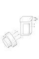
- FIG. 1 is a schematic diagram showing a method for producing hydrogen gas according to an embodiment of the present invention.
- FIG. 2 is a schematic diagram showing a method for producing hydrogen gas according to an embodiment of the present invention.
- FIG. 3 is an image showing an example of a flower-like nanocrystal photographed with a scanning electron microscope (SEM).
- FIG. 4 is an image showing an example of a starfish-like nanocrystal taken by a scanning electron microscope (SEM).
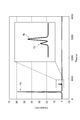
- FIG. 5 is a chromatogram of gas generated in the light irradiation process in Example 2.
- the term “process” is not limited to an independent process, and is included in the term if the purpose of the process is achieved even when it cannot be clearly distinguished from other processes.
- a numerical range indicated by using “to” indicates a range including the numerical values described before and after “to” as the minimum value and the maximum value, respectively.
- the content of each component in the composition means that when there are a plurality of substances corresponding to each component in the composition, the contents of the plurality of substances present in the composition unless otherwise specified. It means the total amount.
- the same components are denoted by the same reference numerals.
- the method for producing hydrogen gas according to the present embodiment includes a light irradiation step.
- a gas containing hydrogen is generated by irradiating the surface of a metal material 4 immersed in water 2 with light L.
- the metal material 4 contains iron.
- the wavelength having the maximum intensity is 360 nm or more and less than 620 nm.
- As the gas is generated at least one of iron oxide and iron hydroxide is formed on the surface of the metal material 4. The location where hydrogen-containing gas is generated is not necessarily found by research.
- a gas containing hydrogen is generated from the vicinity of the surface of the metal material by irradiating the surface of the metal material 4 immersed in the water 2 with light L.
- Near the surface means at least one of the surface of a metal material, iron oxide, and iron hydroxide.
- at least one of water molecules and hydrogen gas may be generated from iron hydroxide.
- nanocrystals containing at least one of iron oxide and iron hydroxide may be formed on the surface of the metal material.
- a method of irradiating the surface of a metal material immersed in water with light to form nanocrystals on the surface of the metal material is referred to as an underwater crystal photosynthesis (SPSC) method. That is, in the method for producing hydrogen gas according to the present embodiment, nanocrystals may be formed on the surface of the metal material by the SPSC method using a metal material containing iron, water, and the light.
- SPSC underwater crystal photosynthesis
- the manufacturing method of the hydrogen gas which concerns on this embodiment in case an iron oxide or an iron hydroxide is a nanocrystal is demonstrated.
- the method for producing hydrogen gas according to the present embodiment is also established when the iron oxide or the iron hydroxide is not a nanocrystal. That is, in the following, the nanocrystal may be referred to as iron oxide or iron hydroxide.
- the hydrogen gas production method according to the present embodiment can easily obtain a large amount of high-purity hydrogen gas as compared with a conventional hydrogen gas production method.
- the method for producing hydrogen gas according to the present embodiment does not require a complicated production process (for example, heating at high temperature, CVD or sputtering) such as an electrode or a photocatalyst.
- hydrogen gas can be produced at room temperature and atmospheric pressure.
- the method for producing hydrogen gas according to this embodiment when the formed iron oxide or iron hydroxide is recovered from the surface of the metal material, the surface of the metal material is exposed again. The exposed surface of the metal material can be reused for hydrogen generation.
- nanocrystals can be formed without using a high-temperature process such as a hydrothermal synthesis reaction and strong alkaline water. From the above, in the method for producing hydrogen gas according to the present embodiment, the production cost of hydrogen gas can be reduced, and the environmental burden associated with the production of hydrogen gas can be reduced.
- iron corrodes means that iron rusts.
- the reaction that iron corrodes is as follows.
- iron is ionized in water to generate Fe 2+ as shown in the following reaction formula (1).
- oxygen is dissolved in water, electrons (e ⁇ ) react with water molecules (H 2 O) and oxygen to generate hydroxide ions (OH ⁇ ) as shown in the following reaction formula (2).
- Fe 2+ further emits electrons to produce Fe 3+ as shown in the following reaction formula (3).
- Fe 3+ reacts with hydroxide ions to produce iron hydroxide (Fe (OH) 3 ) as shown in the following reaction formula (4).
- Desorption of water molecules from iron hydroxide produces iron oxyhydroxide (FeOOH) as shown in the following reaction formula (5).
- iron oxide (Fe 2 O 3 ) that is, rust is generated as shown in the following reaction formula (6).
- hydrogen gas (H 2 ) is not generated in the general iron corrosion reaction as described above.
- crystallinity is deteriorated in iron oxyhydroxide and iron oxide produced by a general iron corrosion reaction.
- iron oxyhydroxide and iron oxide generated by a general iron corrosion reaction are not formed as nanocrystals obtained by the SPSC method according to this embodiment.
- 2Fe ⁇ 2Fe 2+ + 4e ⁇ (1) 2H 2 O + O 2 + 4e ⁇ ⁇ 4OH ⁇ (2)
- the hydroxide ion has arisen also other than reaction shown to the said Reaction formula (2).
- a case where hydroxide ions are present due to dissociation of water molecules and a case where hydroxide ions are present by using alkaline water can be considered.
- the reaction in which iron hydroxide (Fe (OH) 3 ), iron oxyhydroxide (FeOOH), and iron oxide (Fe 2 O 3 ) are generated by these hydroxide ions is a reaction in which the above-mentioned iron rusts. . Therefore, in this case, hydrogen gas is not generated. Further, nanocrystals obtained by the SPSC method according to this embodiment are not formed.
- the surface of the metal material is irradiated with light to generate nanocrystals on the surface of the metal material. Hydrogen gas is generated from the vicinity of the surface.
- the inventors presume that the mechanism by which hydrogen gas is generated by the method for producing hydrogen gas according to the present embodiment is as follows. In the method for producing hydrogen gas according to this embodiment, first, reactions of the above reaction formulas (1) to (4) occur. Thereafter, in the present embodiment, by providing the light irradiation step, at least one of iron oxyhydroxide (FeOOH) and iron oxide (Fe 2 O 3 ) is converted from iron hydroxide (Fe (OH) 3 ).
- the contained nanocrystals grow on the surface of the metal material, and as a by-product, hydrogen gas is generated as well as water molecules.
- iron oxyhydroxide nanocrystals are formed on the surface of the metal material from iron hydroxide, and at least a part of the iron oxyhydroxide nanocrystals is changed to iron oxide nanocrystals.
- water molecules and hydrogen gas are also produced.
- the nanocrystal may be formed, for example, by light-induced tip growth. Light-induced tip growth means that crystal tip growth is promoted in a columnar or needle shape by light irradiation.
- generates is not limited to said reaction mechanism.
- oxygen gas O 2
- the ratio between the number of moles of hydrogen gas produced and the number of moles of oxygen gas produced is 2: 1. That is, based on the stoichiometry, the number of moles of oxygen gas to be generated is 1 ⁇ 2 times the number of moles of hydrogen gas to be generated.
- the number of moles of oxygen in the gas generated in the light irradiation step is 0 times to less than 1/2 times, 0 times to 1/5 times the number of moles of hydrogen.
- the concentration of hydrogen in the gas produced may be greater than 66.7% by volume, 80.0-100% by volume, or 90.0-100% by volume, based on the total volume of the gas.
- the concentration of hydrogen in the gas produced may be greater than 66.7 mol%, based on the total number of moles of all components contained in the gas, 80.0-100 mol%, or 90.0-100 mol %.
- highly pure hydrogen gas is obtained.
- the wavelength having the maximum intensity in the light spectrum used in the light irradiation step is 360 nm or more and less than 620 nm.
- the spectrum of light may be rephrased as the spectral irradiance distribution of light, and the intensity may be rephrased as spectral irradiance or spectral irradiance. That is, in this embodiment, the wavelength of light having the maximum spectral irradiance (intensity) in the spectral radiation distribution (spectrum) of light used in the light irradiation step is 360 nm or more and less than 620 nm.
- the unit of the spectral irradiance (intensity) of light may be, for example, W ⁇ m ⁇ 2 ⁇ nm ⁇ 1 .
- a large amount of high-purity hydrogen gas can be obtained by adjusting the wavelength of light applied to the metal material.
- the crystallinity (crystallinity) of the nanocrystal can be confirmed by, for example, X-ray diffraction (XRD) analysis.
- the composition of iron oxide and iron hydroxide can be confirmed, for example, by point analysis by energy dispersive X-ray analysis (EDX).
- EDX energy dispersive X-ray analysis
- the wavelength is 620 nm or more, it is difficult to generate hydrogen gas and it is difficult to obtain nanocrystals.
- the wavelength is less than 360 nm, it is difficult to obtain high purity hydrogen.
- the nanocrystal is easily decomposed, and the shape of the nanocrystal is easily broken.
- the inventors speculate that the reason why it is difficult to obtain high-purity hydrogen when the wavelength is less than 360 nm is as follows. When the wavelength is less than 360 nm, the nanocrystal acts as a photocatalyst.
- the nanocrystal acts as a photocatalyst, as will be described later, photolysis of water occurs, and not only hydrogen gas but also oxygen gas is generated. As a result, the purity of the obtained hydrogen gas is lowered. Further, the formed iron oxide returns to the iron hydroxide, and the nanocrystal is decomposed.
- the wavelength having the maximum intensity in the spectrum of light used in the light irradiation step is preferably 380 to 600 nm, and more preferably 400 to 580 nm. From the viewpoint of the efficiency of water radiolysis, equipment restrictions, the band gap of iron oxide and iron hydroxide, and the generation of heat energy (exotherm) when excited electrons are relaxed, the above wavelength is: It may be appropriately adjusted within the above range.
- the light source for irradiating the metal material is not particularly limited as long as it can irradiate the light.
- the light source may be, for example, the sun, an LED, a xenon lamp, a mercury lamp, a fluorescent lamp, or the like.
- the light applied to the metal material may be, for example, sunlight or pseudo-sunlight.
- Sunlight can be suitably used from the viewpoint that it can be used as a renewable energy that flows infinitely on the earth and does not emit greenhouse gases.
- Pseudo-sunlight means light that does not use the sun as a light source and whose light spectrum matches the spectrum of sunlight.
- the simulated sunlight can be emitted by a solar simulator using a metal halide lamp, a halogen lamp, or a xenon lamp, for example.
- Pseudo sunlight is generally used for the purpose of evaluating the strength of a material against ultraviolet rays, evaluating solar cells, or evaluating weather resistance.
- simulated sunlight can be suitably used.
- light may be irradiated to the interface where the surface of the metal material is in contact with water.
- the interface is obtained by, for example, a method of immersing a metal material in water, a method of circulating water through part or all of the metal material, and the like.
- the light irradiation step when the water in which the metal material is immersed is irradiated with light, radiolysis of the water may occur.
- a hydrogen radical (H.), a hydroxy radical (.OH), and a hydrated electron (e aq ⁇ ) are generated.
- the hydroxide ion reacts with the hydrated electrons to immediately generate hydroxide ions.
- the generation of hydroxide ions may be promoted by the reaction between the hydroxy radical and the hydrated electron, the production of hydrogen gas may be promoted, and the production of nanocrystals may be promoted. That is, in the light irradiation step, a photochemical reaction accompanied by generation of radicals may occur.
- iron oxide may be formed in advance as a natural oxide film on the surface of the metal material.
- the band gap Eg of iron oxide (Fe 2 O 3 ) contained in the natural oxide film is 2.2 eV. Therefore, the natural oxide film absorbs light by irradiating light having a wavelength of 563 nm or less having energy corresponding to the band gap of iron oxide.
- electrons and holes (h + ) are excited, electrons become hydrated electrons in the process of radiolysis of water, hydrogen gas generation may be promoted, and nanocrystal growth is promoted. Good.
- absorption of light and generation of hydrated electrons in the natural oxide film as described above are not essential for generation of hydrogen gas and generation of nanocrystals.
- the method for producing hydrogen gas according to the present embodiment may further include a surface roughening step of roughening the surface of the metal material before the light irradiation step. That is, in the light irradiation step, the surface of the roughened metal material may be irradiated with light.
- a surface roughening step By performing the surface roughening step, irregularities are formed on the surface of the metal material, the generation of hydrogen gas is easily promoted, and the growth rate of the nanocrystal is easily improved.
- the electron density at the tip of the nanocrystal tends to increase. As a result, it is presumed that a large amount of hydrated electrons are generated at the tip of the nanocrystal, and the generation of the hydroxide ions, the generation of hydrogen gas and the formation of the nanocrystals are promoted.
- the size of the irregularities on the surface of the metal material formed by the surface roughening process is not particularly limited. From the viewpoint of promoting the photochemical reaction, promoting the generation of hydrogen gas, and promoting the growth of nanocrystals, it is preferable that the average size of the bases of the protrusions is 10 nm or more and 500 nm or less, and It is preferable that the average value of the interval between the convex portions to be matched is 2 nm or more and 200 nm or less.
- the average value of the sizes of the bases of the protrusions is more preferably 15 nm or more and 300 nm or less, and the average value of the interval between adjacent protrusions is more preferably 5 nm or more and 150 nm or less.
- the average value of the sizes of the bottoms of the protrusions is more preferably 20 nm or more and 100 nm or less, and the average value of the interval between adjacent protrusions is more preferably 10 nm or more and 100 nm or less.
- the size of the base of the convex portion means the maximum width of the convex portion in a direction perpendicular to the height direction of the convex portion.
- the surface roughening step may be performed by, for example, machining of the surface of the metal material, chemical treatment, or discharge treatment in a liquid.
- the submerged discharge process means a process of discharging in a conductive liquid.
- the mechanical processing include grinding using a polishing paper, buff, or grindstone, blasting, processing using a sandpaper, and the like.
- the chemical treatment include etching with acid or alkali.
- a voltage is applied to a counter electrode composed of an anode and a cathode disposed in a conductive liquid, and the vicinity of the cathode This may be done by generating a plasma and locally melting the cathode.
- irregularities can be formed on the surface of the metal material.
- the submerged discharge treatment may be performed using, for example, the following apparatus.
- An apparatus that performs an in-liquid discharge process includes a cell that contains a conductive liquid, a non-contact electrode pair disposed in the cell, and a DC power source that applies a voltage to the electrode pair.
- the electrode pair is a cathode and an anode.
- a metal material is used for the cathode.
- the material of the anode is not particularly limited as long as it is stable in a conductive liquid without being energized.
- the material of the anode may be platinum or the like, for example.
- the surface area of the anode may be greater than the surface area of the cathode.
- the liquid having conductivity may be, for example, an aqueous potassium carbonate (K 2 CO 3 ) solution.
- the surface of the metal material after the surface roughening step may be exposed to the outside or may be covered with a natural oxide film.
- the metal material is not particularly limited as long as it contains iron.
- the content of iron in the metal material may be 10.0 to 100% by mass, 15.0 to 100% by mass, or 20.0 to 100% by mass based on the total mass of the metal material.
- the higher the iron content in the metal material the easier it is to generate hydrogen gas, the easier it is to generate iron oxide or iron hydroxide, and the easier it is to control the composition of iron oxide or iron hydroxide.
- the metal material may contain, for example, pure iron or an iron alloy, may be made only of pure iron, or may be made only of an iron alloy.
- the metal material may contain iron compounds such as iron sulfide (FeS), iron carbonate (FeCO 3 ), and iron complexes.
- the metal material may contain iron scrap.
- the iron scrap may contain the iron compound. You may use a metal material individually by 1 type or in combination of 2 or more types.
- the iron alloy is not particularly limited as long as it is an alloy containing iron.
- the iron content in the iron alloy is preferably 10.0 to 99.8% by mass from the viewpoint of promoting the generation of hydrogen gas and the productivity of nanocrystals, and 15.0 to 99.5% by mass. Is more preferably 20.0 to 99.0% by mass, and particularly preferably 25.0 to 99.0% by mass.
- iron alloys include Fe—C alloys, Fe—Au alloys, Fe—Al alloys, Fe—B alloys, Fe—Ce alloys, Fe—Cr alloys, and Fe—Cr—Ni alloys.
- iron alloys Fe-C alloy, Fe-Cr alloy, Fe-Cr-Ni alloy, Fe-Cr-Mo alloy, Fe-Cr-Al alloy, Fe-Cr-Ti alloy, Fe-Cr-Ni-Mn alloy, Fe-Cu alloy, Fe-Mg alloy, Fe-Mn alloy, Fe-Mo alloy, Fe-Nb alloy, Fe-Ni alloy, Fe-P alloy Alloys, Fe-Si based alloys, Fe-Si-Ag based alloys, Fe-Si-Mg based alloys, Fe-Ti based alloys, and Fe-Zn based alloys are also widely used industrially and have the characteristics inherent in iron. It can be suitably used in the same manner as pure iron from the viewpoints of being provided and corrosion resistance in water.
- the metal material may further contain other atoms inevitably mixed.
- other atoms inevitably mixed include Ag, C, Mn, Sb, Si, K, Na, Li, Ba, Sr, Ca, Mg, Be, Zn, Pb, Cd, Tl, V, and Al. , Zr, W, Mo, Ti, Co, Ni, Au, and the like.
- the content of the atoms contained in the metal material may be, for example, 3% by mass or less based on the total mass of the metal material.
- the content of the atoms contained in the metal material is preferably 1% by mass or less from the viewpoint of promoting the generation of hydrogen gas and the productivity of nanocrystals.
- the shape of the metal material is not particularly limited.
- Examples of the shape of the metal material include a plate shape, a block shape, a ribbon shape, a round wire shape, a sheet shape, a mesh shape, or a shape obtained by combining these.
- the shape of the metal material is preferably a plate shape, a block shape, or a sheet shape from the viewpoint of the recoverability of hydrogen gas and nanocrystals and the workability of immersion in water.
- the method for producing the metal material is not particularly limited.
- Examples of the method for producing the metal material include industrially widely used techniques such as a reduction method, a blast furnace method, an electric furnace method, and a smelting reduction method.
- the reduction method means a method of removing oxygen from iron oxide contained in iron ore to extract iron.
- the water in which the metal material is immersed is selected from the group consisting of pure water, ion exchange water, rain water, tap water, river water, well water, filtered water, distilled water, reverse osmosis water, spring water, spring water, dam water, and seawater. May be at least one kind.
- pure water, ion-exchanged water, and tap water are preferable from the viewpoint of promoting the generation of hydrogen gas and controlling the composition of nanocrystals and productivity.
- river water, well water, dam water, seawater, etc. can be used suitably as naturally derived water.
- the pH of the water may be 5.00 to 10.0.
- the pH of water is preferably 5.5 to 9.5, and more preferably 6.0 to 9.0, from the viewpoint of controlling the composition of the nanocrystals.
- the pH of the water may be 5.5 to 8.2, or 5.5 to 7.5.
- the pH of water may be measured by, for example, a pH meter (LAQUAact, portable pH meter / water quality meter) manufactured by Horiba, Ltd.
- LAQUAact portable pH meter / water quality meter
- the electrical conductivity of water may be 80000 ⁇ S / cm or less.
- the electrical conductivity of water is 10000 ⁇ S / cm or less from the viewpoint of promoting the generation of hydrogen gas and enhancing the crystallinity of nanocrystals while suppressing corrosion of metal materials in water (conventional rust formation reaction). Is preferably 5000 ⁇ S / cm or less, and more preferably 1.0 ⁇ S / cm or less.
- the lower limit value of the electrical conductivity of water may be, for example, 0.05 ⁇ S / cm.
- the electrical conductivity of water may be measured by, for example, a pH meter (LAQUAact, portable pH meter / water quality meter) manufactured by Horiba, Ltd.
- LAQUAact portable pH meter / water quality meter
- Water purity is not particularly limited.
- the purity of water means the ratio of the mass of water molecules contained in water.
- the purity of water may be, for example, 80.0% by mass or more based on the total mass of water. By setting the purity of water to 80.0% by mass or more, the influence of impurities under light irradiation can be suppressed. Examples of the influence of impurities include salt precipitation and formation of an immobile film.
- the purity of water is preferably 85.0% by mass or more and more preferably 90.0% by mass or more from the viewpoint of promoting the generation of hydrogen gas and controlling the composition of the nanocrystals.
- the upper limit of the purity of water may be 100.0 mass%, for example.
- Water purity may be controlled by electrical conductivity. For example, when the type of solute (impurity) dissolved in water is specified and the purity of water is in the above range, the concentration of solute and electrical conductivity are often in a proportional relationship. On the other hand, in water in which a plurality of solutes (impurities) are mixed, it is difficult to determine the purity of water from the measured electric conductivity.
- the purity of water is preferably managed by the electrical conductivity of water.
- the concentration of dissolved oxygen in water is not particularly limited.
- the concentration of dissolved oxygen in water is, for example, based on the total volume of water, from the viewpoint of promoting the generation of hydrogen gas by light irradiation, promoting the growth reaction of nanocrystals, and preventing corrosion of metal materials in water. 15 mg / L or less is preferable, 12 mg / L or less is more preferable, and 10 mg / L or less is more preferable.
- the lower limit value of the concentration of dissolved oxygen in water may be, for example, 8.0 mg / L.
- the concentration of dissolved oxygen in water may be measured, for example, with a pH meter (LAQUAact, portable pH meter / water quality meter) manufactured by Horiba, Ltd.
- LAQUAact portable pH meter / water quality meter
- Water temperature is not particularly limited.
- the temperature of water is, for example, preferably from 0 to 80 ° C., more preferably from 2 to 75 ° C., and even more preferably from 5 to 70 ° C., from the viewpoint of preventing solidification and evaporation of water and preventing corrosion of the metal material.
- the nanocrystal may contain at least one of iron oxide and iron hydroxide.
- the nanocrystal may be made of iron oxide and iron hydroxide, may be made only of iron oxide, or may be made only of iron hydroxide.
- the iron oxide contained in the nanocrystal include FeO, ⁇ -Fe 2 O 3 , ⁇ -Fe 2 O 3 , Fe 3 O 4 , Cr 2 FeO 4 , CoFe 2 O 4 , and ZnFe 2 O 4. It's okay.
- Iron hydroxide contained in the nanocrystals for example, Fe (OH) 3, FeOOH , may be Fe 5 HO 8 ⁇ 4H 2 O and the like.
- the shape of the nanocrystal may be at least one selected from the group consisting of needle shape, column shape, rod shape, tube shape, flake shape, lump shape, flower shape, starfish shape, branch shape and convex shape.
- the flower shape means a shape in which a plurality of columnar crystals extend radially from the center of the crystal.
- the starfish shape means a shape in which a plurality of columnar crystals extend from the center of the crystal at almost equal intervals in the same plane.
- the maximum width (eg, length) of the nanocrystal may be 2 nm to 10 ⁇ m, or 2 nm to 1000 nm.
- the maximum width of a nanocrystal implies the maximum width of an aggregate of a plurality of nanocrystals.
- the height of the nanocrystal from the surface of the metal material is not particularly limited.
- the nanocrystal may be a solid structure or a hollow structure.
- the concentration of hydrogen in the generated gas may be measured by gas chromatography mass spectrometry.
- the apparatus used for measurement may be a general gas chromatograph.
- a gas chromatograph for example, GC-14B manufactured by Shimadzu Corporation may be used.
- Measurement using a gas chromatograph may be performed by putting argon as a carrier gas and a sample into a syringe.
- the concentration of hydrogen gas in consideration of air contamination.
- nitrogen (N) is not contained in the metal material and water and the analyzed gas contains nitrogen gas (N 2 )
- N 2 nitrogen gas
- the volume of generated hydrogen gas can be obtained by subtracting the total volume of nitrogen gas and the volume of components excluding nitrogen gas (for example, oxygen gas) from the mixed air from the total volume of analyzed gas. it can.
- the generated gas can be regarded as only hydrogen gas and oxygen gas.
- the container 6a may include a container body 8a that houses the water 2 and the metal material 4, and a lid 10a.
- the container 6a may not include the lid body 10a.
- the container 6a preferably includes a lid body 10a from the viewpoint of collecting hydrogen gas.
- the lid 10a may seal the container body 8a.
- the light L may be irradiated using a lamp (light source) 12.
- the lamp 12 By using the lamp 12, the surface of the metal material can be irradiated with light having a certain intensity.
- the position of the lamp 12 may be appropriately adjusted so that hydrogen gas is effectively generated.
- the lamp 12 may not be used.
- the position and orientation of the container 6a may be appropriately adjusted so that the surface of the metal material 4 is irradiated with sunlight.
- the metal material 4 may have a light-irradiated surface upright, or a light-irradiated surface as shown in FIG.
- the distance from the water surface to the light irradiation surface of the metal material 4 can be appropriately set according to the type of the metal material and water, and is not particularly limited.
- the distance may be 5 mm to 10 m, for example.
- the distance is preferably 5 mm to 8 m, more preferably 5 mm to 5 m, from the viewpoint of suppressing the reduction of the effect due to light scattering, promoting the generation of hydrogen gas, and collecting the nanocrystals.
- the shape of the container body 8a is not particularly limited.
- the shape of the container main body 8a may be a rectangular parallelepiped shape like the container main body 8a shown in FIG. 1, or may be cylindrical like the container main body 8b included in the container 6b shown in FIG.
- the shape of the container body 8a may be appropriately selected so that light can be effectively irradiated onto the surface of the metal material 4.
- the shape of the lid 10a is not particularly limited.
- the shape of the lid body 10a may be a rectangular parallelepiped shape like the lid body 10a shown in FIG. 1, or may be cylindrical like the lid body 10b shown in FIG.
- a material that can effectively irradiate the surface of the metal material 4 with light may be used as appropriate.
- the material of the container 6a (the container body 8a and the lid body 10a) is not particularly limited as long as it does not block light from being irradiated on the surface of the metal material.
- the material of the container body 8a and the lid 10a is preferably one that does not react with water.
- the material of the container body 8a and the lid body 10a may be, for example, glass or plastic. From the viewpoint of collecting generated hydrogen gas, the material of the container body 8a and the lid body 10a is preferably glass.
- the method for producing steel according to the present embodiment includes a step of forming at least one of iron oxide and iron hydroxide on the surface of a metal material by the method for producing hydrogen gas according to the present embodiment, Removing and recovering at least one of oxide and iron hydroxide from the surface of the metal material, and using the metal material from which at least one of iron oxide and iron hydroxide is removed And a step of manufacturing steel.
- a gas containing hydrogen is generated, and at least one of iron oxide and iron hydroxide is formed. Containing nanocrystals may be formed on the surface of the metal material.
- the steel manufacturing method according to the present embodiment may further include at least one of a separation process, a purification process, and a recovery process for the hydrogen gas generated in the light irradiation process.
- a separation process since the purity of the hydrogen gas to be generated is high, the separation step and the purification step may be omitted.
- the mechanism of the reaction in which hydrogen is generated with iron oxide or iron hydroxide is not necessarily elucidated.
- the present inventors consider that one of the hydrogen generation reaction mechanisms is a photocatalytic reaction in which iron oxide or iron hydroxide (for example, nanocrystal) itself functions as a photocatalyst.
- the photocatalytic reaction by iron oxide or iron hydroxide is not a dominant reaction, and as described above, iron oxohydroxide (FeOOH) and iron oxide (Fe 2 O).
- FeOOH iron oxohydroxide
- Fe 2 O iron oxide
- the photocatalytic reaction whose reaction mechanism is relatively known will be described.
- the photocatalytic reaction in the case where the iron oxide or iron hydroxide is a nanocrystal will be described.
- the photocatalytic reaction described below is also established when the iron oxide or iron hydroxide is not a nanocrystal.
- the reaction in which hydrogen gas is generated together with nanocrystals is different from the photolysis reaction of water using a photocatalyst such as titanium dioxide (TiO 2 ).
- a photocatalyst such as titanium dioxide (TiO 2 ).
- the reaction in which hydrogen gas is generated in the photocatalytic reaction with titanium dioxide is as follows.
- the band gap Eg of titanium dioxide is 3.2 eV. Accordingly, when titanium dioxide immersed in water is irradiated with light having a wavelength of 380 nm or less having energy corresponding to the band gap of titanium dioxide, the titanium dioxide absorbs light. As a result, electrons and holes are excited. The holes oxidize water to generate oxygen gas as shown in the following reaction formula (7).
- the electrons reduce hydrogen ions (H + ) to generate hydrogen gas as shown in the following reaction formula (8).
- the energy level of the conduction band of titanium dioxide is negative when the hydrogen generation potential is taken as a reference (zero), and hydrogen is in a 2: 1 molar ratio (stoichiometric ratio). Gas and oxygen gas are generated.
- the energy level of the conduction band of nanocrystals is positive, and the molar ratio of hydrogen and oxygen in the generated gas does not necessarily satisfy the stoichiometric ratio.
- the present inventors presume that the reaction mechanism in which hydrogen gas is generated in the photocatalytic reaction by nanocrystals is as follows.
- the iron oxide or iron hydroxide By irradiating the nanocrystal with light having energy corresponding to the band gap of iron oxide or iron hydroxide, the iron oxide or iron hydroxide absorbs light.
- the iron oxide is iron oxide (Fe 2 O 3 )
- the band gap Eg is 2.2 eV
- the wavelength of light having energy corresponding to the band gap is 563 nm or less.
- iron oxide or iron hydroxide absorbs light, electrons and holes are excited. The holes oxidize water to generate oxygen gas as shown in the above reaction formula (7).
- the electrons reduce hydrogen ions to generate hydrogen gas as shown in the above reaction formula (8).
- the photocatalytic conduction band is obtained when the band gap of the photocatalyst is large and the hydrogen generation potential is the reference (zero). It is necessary to satisfy the condition that the energy level of is negative. Titanium dioxide satisfies this condition, but the energy level of the conduction band of titanium dioxide is close to the hydrogen generation potential. Titanium dioxide has low catalytic activity for hydrogen generation. Therefore, in order to actually use titanium dioxide as a photocatalyst for water decomposition, a platinum (Pt) electrode is provided on the counter electrode of titanium dioxide, and a negative bias voltage (for example, about ⁇ 0.5 V) is provided on the titanium dioxide side. It may have to be applied.
- Pt platinum
- the band gap of nanocrystals made of iron oxide is narrower than that of titanium dioxide, by using light having a longer wavelength than that of titanium dioxide, a photocatalyst by nanocrystals is used.
- the reaction proceeds.
- the energy level of the conduction band of iron oxide is positive with respect to the hydrogen generation potential.
- hydrogen is not generated without a bias voltage when the energy level of the conduction band of the photocatalyst is positive.
- the present inventors presume that hydrogen is generated by a chemical bias without a bias voltage as follows.
- nanocrystal growth occurs through the reaction of hydroxide ions generated by the radiolysis of water or the reaction of water and holes with Fe 3+ . Therefore, the pH of water is locally shifted to the alkali side, particularly at the tip of the nanocrystal. As a result, this becomes a chemical bias, charge separation between electrons and holes proceeds efficiently, and hydrogen ions are reduced by the electrons to promote a reaction that generates hydrogen gas.
- the photocatalytic reaction using the nanocrystals described above does not require the use of two types of electrodes, a positive electrode and a negative electrode, and can generate hydrogen gas using visible light. Industrially superior to reaction.
- the gas generated in the photocatalytic reaction by nanocrystals may be mostly hydrogen gas.
- the concentration of hydrogen in the generated gas may be higher than the concentration of hydrogen calculated stoichiometrically from the molecular formula (H 2 O) of water. That is, the concentration of hydrogen in the generated gas may be greater than 66.7% by volume based on the total volume of the gas.
- the concentration of hydrogen in the gas produced may be greater than 66.7 mol%, based on the total number of moles of all components contained in the gas.
- the inventors presume that the mechanism by which high-purity hydrogen gas is obtained in the photocatalytic reaction with nanocrystals is as follows.
- oxygen gas is generated by the reaction of water and holes. Even if oxygen gas is generated, oxygen gas and iron ions ionized in water (Fe 2+ or Fe 3+) ) Reacts directly. As a result, the growth of iron oxide is promoted, the concentration of oxygen in the gas is reduced, and the concentration of hydrogen is increased. Further, since the solubility in water is higher for oxygen gas than for hydrogen gas, the concentration of hydrogen gas in the generated gas becomes higher.
- Example 1 the metal material was prepared by the method shown below, and the surface roughening process and the light irradiation process were performed.
- Metal material Iron having a purity of 99.5% by mass was rolled to form a plate-like metal material.
- the metal material had a size of 50 mm ⁇ 10 mm and a thickness of 0.5 mm.
- the surface of the metal material after the surface roughening step was observed using a scanning electron microscope.
- a scanning electron microscope JSM-7001F manufactured by JEOL Ltd. was used.
- many irregularities were formed on the surface of the metal material.
- the size of the base of the convex part was 5 nm on average.
- the light irradiation process was performed by the method shown below. Pure water was put into a glass container, and the metal material after the surface roughening step was immersed in pure water. The pH and electrical conductivity of pure water were measured with a pH meter. As the pH meter, LAQUAact (portable pH meter / water quality meter) manufactured by Horiba, Ltd. was used. The pH of pure water was 7.0, and the electric conductivity of pure water was 1.0 ⁇ S / cm or less. The container was sealed with a plastic lid.
- a metal material, a container, and a light source were arranged, and light was irradiated on the surface of the metal material. That is, the surface of the metal material was irradiated with light from a direction perpendicular to the surface of the metal material.
- a xenon lamp was used as the light source.
- a spot light source (LightingCureLC8) manufactured by Hamamatsu Photonics Co., Ltd. was used.
- a special optical filter was attached to the xenon lamp, and the light wavelength range was set to 400 to 600 nm.
- the surface of the metal material was irradiated with light for 48 hours. The light output was 280W.
- the spectral spectrum of light was measured with a spectroradiometer.
- SOLO 2 manufactured by Gentec-EO was used as the spectroradiometer.
- the wavelength having the maximum intensity was 360 nm or more and less than 620 nm.
- the wavelength having the maximum intensity was about 493 nm.
- the light intensity at the light irradiation position 5 cm away from the light source was 3025 Wm ⁇ 2 .
- the light irradiation position may be rephrased as the position of the surface of the metal material.
- Example 2 the same metal material as in Example 1 was prepared. Next, a surface roughening step was performed in the same manner as in Example 1. Subsequently, the light irradiation process was performed like Example 1 except the following points. In the light irradiation process of Example 2, the light irradiation time was 72 hours.
- Example 3 In Example 3, the same metal material as in Example 2 was prepared. Next, a surface roughening step was performed in the same manner as in Example 2. Subsequently, the light irradiation process was performed like Example 2 except the following points.
- the surface of the metal material was irradiated with simulated sunlight without using a xenon lamp as a light source.
- a solar simulator (HAL-320) manufactured by Asahi Spectroscopy Co., Ltd. was used as a light source for simulated sunlight.
- the solar simulator uses a xenon lamp.
- the wavelength range of pseudo sunlight emitted by the solar simulator is 350 to 1100 nm.
- a metal material, a container, and a light source were arranged. That is, the surface of the metal material was irradiated with light from a direction perpendicular to the surface of the metal material.
- the light output was 300W.
- the spectral spectrum of light was measured with the above spectroradiometer.
- the wavelength having the maximum intensity was 360 nm or more and less than 620 nm.
- the wavelength having the maximum intensity was about 460 nm.
- the intensity of light at a light irradiation position 60 cm away from the light source was 1000 W / m 2 .
- Example 4 In Example 4, the same metal material as in Example 2 was prepared. Next, a surface roughening step was performed in the same manner as in Example 2. Subsequently, the light irradiation process was performed like Example 2 except the following points.
- Example 5 In Example 5, the same metal material as in Example 3 was prepared. Next, a surface roughening step was performed in the same manner as in Example 3. Subsequently, the light irradiation process was performed like Example 3 except the following points.
- river water was used instead of pure water.
- the pH and electrical conductivity of river water were measured with the pH meter.
- the pH of the river water was 7.5 and the electric conductivity of the river water was 350 ⁇ S / cm.
- Example 6 the same metal material as in Example 3 was prepared. Next, a surface roughening step was performed in the same manner as in Example 3. Subsequently, the light irradiation process was performed like Example 3 except the following points.
- seawater was used instead of pure water.
- the pH and electrical conductivity of seawater were measured with the pH meter.
- the pH of the seawater was 8.2
- the electrical conductivity of the seawater was 55000 ⁇ S / cm.
- Example 7 a metal material was prepared in the same manner as in Example 3. Subsequently, the following surface roughening process was performed. Next, a light irradiation process was performed in the same manner as in Example 3.
- the surface of the metal material was polished with abrasive paper by the method described below. First, the surface of the metal material immersed in water was polished with # 400 water-resistant abrasive paper, and then the surface of the metal material was polished with # 800 water-resistant abrasive paper. As water-resistant abrasive paper, abrasive paper manufactured by Fujimoto Kagaku Co., Ltd. was used. The surface of the metal material after the surface roughening step was observed using the scanning electron microscope. As a result, many irregularities were formed on the surface. The distance between adjacent convex portions was 13 ⁇ m on average.
- Example 8 In Example 8, the following metal materials were prepared. Next, in the same manner as in Example 3, a surface roughening step and a light irradiation step were performed.
- the Fe—Cr—Ni alloy was rolled to form a plate-like metal material.
- the metal material had a size of 50 mm ⁇ 10 mm and a thickness of 0.5 mm.
- the Fe—Cr—Ni alloy was an austenitic stainless steel containing 70.3% by mass of Fe, 18.2% by mass of Cr, and 11.5% by mass of Ni.
- Example 9 In Example 9, the following metal materials were prepared. Next, in the same manner as in Example 3, a surface roughening step and a light irradiation step were performed.
- the Fe—C alloy was rolled to form a plate-like metal material.
- the metal material had a size of 50 mm ⁇ 10 mm and a thickness of 0.5 mm.
- the Fe—C alloy was cast iron containing 96.5% by mass of Fe and 3.5% by mass of C.
- Example 10 In Example 10, the following metal materials were prepared. Next, in the same manner as in Example 3, a surface roughening step and a light irradiation step were performed.
- Metal material As a metal material, iron scrap generated when manufacturing a cutting tool was used. The shape of the iron scrap was plate-like. The dimensions of the iron scrap were 50 mm ⁇ 250 mm and thickness 10 mm. The iron scrap contained 77.8% by mass of Fe, 17.8% by mass of W, 4.2% by mass of Cr, and 0.2% by mass of C. Iron scrap was classified as chromium tungsten steel scrap based on Japanese Industrial Standards (JIS) iron scrap classification criteria G2401 and G4404. There was no scratch on the surface of the iron scrap, and there was no trace of welding or painting.
- JIS Japanese Industrial Standards
- Example 11 a metal material was prepared in the same manner as in Example 1. Subsequently, the following surface roughening process was performed. Next, a light irradiation process was performed in the same manner as in Example 1.
- the surface of the metal material was polished so as to be a mirror surface.
- the surface of the metal material was polished with # 2000 water-resistant polishing paper.
- As the water resistant abrasive paper water resistant abrasive paper manufactured by Fujimoto Kagaku Co., Ltd. was used.
- the surface of the metal material was polished using a table polishing machine, a polishing buff and a diamond abrasive.
- the particle size of the diamond abrasive was 0.25 ⁇ m.
- “RPO-128K Refine Polisher, 200HV” manufactured by Refine Tech Co., Ltd. was used.
- Both the polishing buff and the diamond abrasive were manufactured by Refine Tech Co., Ltd.
- the surface of the metal material after the surface roughening step was observed using the scanning electron microscope. As a result, clear irregularities were not formed on the surface of the metal material after the surface roughening step of Example 11.
- Example 12 a metal material was prepared in the same manner as in Example 3. Next, a surface roughening step was performed in the same manner as in Example 3. Subsequently, the light irradiation process was performed like Example 3 except the following points.
- Example 12 In the light irradiation process of Example 12, pure water to which dilute hydrochloric acid aqueous solution was added was used instead of pure water. The pH and electrical conductivity of pure water were measured with the pH meter. As a result, the pH of pure water was 5.5, and the electric conductivity of pure water was 1.0 ⁇ S / cm or less.
- Example 13 the same metal material as in Example 8 was prepared. Next, a surface roughening step was performed in the same manner as in Example 4. Subsequently, the light irradiation process was performed like Example 4 except the following points.
- river water was used instead of pure water.
- the pH and electrical conductivity of river water were measured with the pH meter.
- the pH of river water was 7.5.
- the electric conductivity of river water was 350 ⁇ S / cm.
- Example 14 In Example 14, the same metal material as in Example 1 was prepared. Subsequently, the light irradiation process was performed like Example 1 without performing the surface roughening process.
- Example 15 the same metal material as in Example 4 was prepared. Next, a surface roughening step was performed in the same manner as in Example 7. Next, a light irradiation process was performed in the same manner as in Example 4.
- Example 16 the same metal material as in Example 2 was prepared. Next, a surface roughening step was performed in the same manner as in Example 2. Subsequently, the light irradiation process was performed like Example 2 except the following points.
- Example 16 In the light irradiation step of Example 16, a dedicated optical filter was attached to the xenon lamp used in Example 2 to set the light wavelength range to 500 to 800 nm.
- the surface of the metal material was irradiated with light for 72 hours.
- the light output was 280W.
- the spectral spectrum of light was measured with the above spectroradiometer.
- the wavelength having the maximum intensity was 360 nm or more and less than 620 nm.
- the wavelength having the maximum intensity was about 600 nm.
- the intensity of light at a light irradiation position 60 cm away from the light source was 1000 W / m 2 .
- Example 17 the same metal material as in Example 2 was prepared. Next, a surface roughening step was performed in the same manner as in Example 2. Subsequently, the light irradiation process was performed like Example 2 except the following points.
- a UV lamp was used instead of a xenon lamp as a light source.
- B-100AP manufactured by UVP was used as the UV lamp.
- the surface of the metal material was irradiated with light for 72 hours.
- the light output was 100 W.
- the spectral spectrum of light was measured with the above spectroradiometer.
- the wavelength having the maximum intensity was 360 nm or more and less than 620 nm.
- the wavelength having the maximum intensity was about 365 nm.
- the light intensity at the light irradiation position 20 cm away from the light source was 100 W / m 2 .
- Comparative Example 1 In Comparative Example 1, the same metal material as in Example 1 was prepared. Next, a surface roughening step was performed in the same manner as in Example 1. Subsequently, pure water was put into a glass container, and the metal material after the surface roughening step was immersed in pure water. The pH and electrical conductivity of pure water were measured with the pH meter. As a result, the pH of pure water was 7.0, and the electric conductivity of pure water was 1.0 ⁇ S / cm or less. The container was sealed with a plastic lid and held for 72 hours. In Comparative Example 1, the light irradiation process was not performed.
- Comparative Example 2 In Comparative Example 2, the same metal material as in Example 1 was prepared. Next, a surface roughening step was performed in the same manner as in Example 1. Subsequently, the light irradiation process was performed like Example 1 except the following points.
- an infrared lamp was used instead of the xenon lamp.
- a SICCA 250 W 240 V infrared lamp manufactured by OSRAM Co., Ltd. was used as the infrared lamp.
- the wavelength of the light of the infrared lamp is greater than 1000 nm.
- the spectral spectrum of light was measured with the above spectroradiometer.
- the wavelength having the maximum intensity was 620 nm or more.
- the wavelength having the maximum intensity was about 1100 nm.
- the average light intensity at the light irradiation position was 35 W / m 2 .
- Comparative Example 3 In Comparative Example 3, the same metal material as in Example 3 was prepared. Next, a surface roughening step was performed in the same manner as in Example 3. Subsequently, the light irradiation process was performed like Example 3 except the following points.
- acetone was used instead of pure water.
- acetone purity 99.5 mass%) manufactured by Wako Pure Chemical Industries, Ltd. was used.
- Comparative Example 4 In Comparative Example 4, the same metal material as in Example 2 was prepared. Next, a surface roughening step was performed in the same manner as in Example 2. Subsequently, the light irradiation process was performed like Example 2 except the following points.
- a dedicated optical filter was attached to the xenon lamp used in Example 2 to set the light wavelength range to 600 to 1000 nm.
- the surface of the metal material was irradiated with light for 72 hours.
- the light output was 280W.
- the spectral spectrum of light was measured with the above spectroradiometer.
- the wavelength having the maximum intensity was 620 nm or more.
- the wavelength having the maximum intensity was about 820 nm.
- the intensity of light at a light irradiation position 60 cm away from the light source was 1000 W / m 2 .
- Table 1 shows the conditions of the metal materials, surface roughening process, water, and light irradiation process of Examples 1 to 17 and Comparative Examples 1 to 4.
- GC-14B As a gas chromatograph, GC-14B manufactured by Shimadzu Corporation was used. As the volume of the product gas, a value (unit: cc / cm 2 ) per light irradiation area on the surface of the metal material was calculated. Moreover, when nitrogen is not contained in the metal material and water before use, and the analyzed gas contains nitrogen gas, the volume of nitrogen and oxygen derived from the air is determined by the method described above. The concentration of the produced hydrogen gas was corrected so as to be excluded from the total volume of the produced gas.
- Examples 1 to 17 and Comparative Example 4 it was visually confirmed that gas was accumulated in the container after the light irradiation process.
- Tables 2 and 3 show the volume of the product gas in each of Examples 1 to 17 and Comparative Example 4.
- Comparative Examples 1 to 3 no gas was generated.
- hydrogen gas (H 2 ), nitrogen gas (N 2 ), and oxygen gas (O 2 ) were detected from the gases of Examples 1 to 17 and Comparative Example 4. It was also found that hydrogen gas (H 2 ) was dominant in each of Examples 1 to 17 and Comparative Example 4. However, the volume of the product gas in Comparative Example 4 was smaller than the volume of the product gas in Examples 1 to 17.
- FIG. 5 is a chromatogram of the gas generated in the light irradiation step in Example 2.
- the volume ratio of hydrogen gas (H 2 ): oxygen gas (O 2 ): nitrogen gas (N 2 ) was 52: 1: 3.
- nitrogen was not contained in the metal material and water before use. Therefore, the nitrogen gas detected by gas chromatography mass spectrometry is considered to be due to air contamination during analysis.
- the volume ratio of oxygen gas: nitrogen gas was 2: 7 in air. Based on this result, the corrected hydrogen gas concentration (unit: volume%) was calculated by the method described above.
- the concentration of hydrogen gas in Example 2 was 99.7% by volume.
- the hydrogen gas concentration after correction was calculated in the same manner as in Example 2.
- the hydrogen gas concentrations of Examples 1 to 17 and Comparative Example 4 are shown in Tables 2 and 3, respectively.
- Crystal phase The surface of the metal material after each light irradiation step in each of Examples 1 to 17 and Comparative Examples 1 to 4 is individually analyzed by the X-ray diffraction (XRD) method to identify main crystal phases generated on the surface of the metal material. did.
- XRD X-ray diffraction
- the surface of the metal material was irradiated with Cu-K ⁇ rays using an X-ray diffractometer.
- the measurement conditions for the XRD analysis were as follows. As the X-ray diffractometer, ATG-G (powder X-ray diffraction) manufactured by Rigaku Corporation was used.
- the main crystalline phases detected are shown in Tables 2 and 3. Output: 50kV-300mA Scan speed: 4.0 ° / min Measurement mode: ⁇ -2 ⁇ Diffraction angle: 10-60 °
- Example 3 As shown in Tables 2 and 3, in Examples 1 to 17, the volume of the generated gas per light irradiation area exceeded 1 cc / cm 2 , and high concentration hydrogen gas was generated. It was. In addition, as shown in Tables 2 and 3, there was a tendency that a difference in the volume of the generated gas occurred depending on the iron content in the metal material, the pH of the water, or the electrical conductivity. Here, it was found that the volume of the gas generated in Example 3 was larger than the volume of the gas generated in Example 7. Example 3 and Example 7 differ only in the method of the surface roughening process for the surface of the metal material. The present inventors consider that the reason why the volume of the product gas in Example 3 is larger than the volume of the product gas in Example 7 is as follows.
- Example 3 The unevenness on the surface of the metal material formed by the submerged discharge treatment in Example 3 is finer than the unevenness on the surface of the metal material formed by polishing in Example 7. For this reason, the electron density at the tip of the nanocrystal of Example 3 is increased, and many hydrated electrons are generated at the tip of the nanocrystal. As a result, the generation of hydroxide ions, the formation of nanocrystals, and the generation of hydrogen gas are further promoted. Furthermore, it was found that the volume of the gas generated in Example 1 was larger than the volume of the gas generated in Example 11. Example 1 and Example 11 differ only in the method of the surface roughening process for the surface of the metal material.
- the present inventors consider that the reason why the volume of the product gas of Example 1 is larger than the volume of the product gas of Example 11 is as follows.
- the unevenness on the surface of the metal material formed by the submerged discharge treatment in Example 1 is finer than the unevenness on the surface of the metal material formed by polishing in Example 11.
- the electron density at the tip of the nanocrystal of Example 1 increases, and many hydrated electrons are generated at the tip of the nanocrystal.
- the generation of hydroxide ions, the formation of nanocrystals, and the generation of hydrogen gas are further promoted.
- Comparative Example 1 Fe (OH) 3 was detected on the surface of the metal material by XRD analysis. However, in Comparative Example 1, Fe (OH) 3 was uniformly distributed on the surface of the metal material. In Comparative Example 1, no gas was generated in the light irradiation process. From the above, it is considered that the surface of the metal material after the light irradiation process of Comparative Example 1 was iron rusted in water.
- Comparative Example 2 since the irradiated light was infrared light, it is considered that the reaction for forming the nanocrystal did not proceed. In Comparative Example 2, since the irradiated light was infrared light, the natural oxide film (for example, Fe 2 O 3 ) originally present in the metal material does not absorb light, and the above-described photochemical reaction does not proceed. You can also think.
- the natural oxide film for example, Fe 2 O 3
- Comparative Example 3 since the metal material was immersed in acetone instead of water, it was considered that no hydroxide ions were present and nanocrystals were not formed. Acetone does not cause radiolysis of water even when irradiated with light, and there are no dissociated hydroxide ions.
- Comparative Example 4 almost no nanocrystals were confirmed. In Comparative Example 4, since the wavelength having the maximum intensity in the irradiated light spectrum was 620 nm or more, it is considered that formation and growth of nanocrystals were difficult to occur. That is, in Comparative Example 4, at least one of iron oxyhydroxide (FeOOH) and iron oxide (Fe 2 O 3 ) is generated from iron hydroxide (Fe (OH) 3 ) generated according to the above reaction formula (4). It is considered that the reaction in which the nanocrystals containing phosphine are difficult to proceed and the light-induced tip growth of the nanocrystals is difficult to occur.
- FeOOH iron oxyhydroxide
- Fe 2 O 3 iron oxide
- Fe (OH) 3 iron hydroxide
- the volume of the product gas of Comparative Example 4 was smaller than the volume of the product gas of Examples 1 to 17.
- Comparative Example 4 since the generation and growth of nanocrystals were difficult to occur, it is considered that the generation of water molecules and hydrogen gas associated therewith was difficult to occur.
Landscapes
- Chemical & Material Sciences (AREA)
- Organic Chemistry (AREA)
- Engineering & Computer Science (AREA)
- Inorganic Chemistry (AREA)
- Chemical Kinetics & Catalysis (AREA)
- Materials Engineering (AREA)
- Metallurgy (AREA)
- Health & Medical Sciences (AREA)
- General Health & Medical Sciences (AREA)
- Combustion & Propulsion (AREA)
- Mechanical Engineering (AREA)
- Electrochemistry (AREA)
- Manufacturing & Machinery (AREA)
- Catalysts (AREA)
- Electrolytic Production Of Non-Metals, Compounds, Apparatuses Therefor (AREA)
- Compounds Of Iron (AREA)
- ing And Chemical Polishing (AREA)
Abstract
Description
(1)原材料が安価である。
(2)原材料の加工にコストがかからない。
(3)プロセス及び装置が簡易であり、大型化できる。
2Fe→2Fe2++4e- (1)
2H2O+O2+4e-→4OH- (2)
2Fe2+→2Fe3++2e- (3)
Fe3++3OH-→Fe(OH)3 (4)
Fe(OH)3→FeOOH+H2O (5)
2FeOOH→Fe2O3+H2O (6)
本実施形態において鉄酸化物又は鉄水酸化物(例えば、ナノ結晶)に伴い水素が生成する反応の機構は必ずしも解明されていない。本発明者らは、水素の生成反応機構の一つが、鉄酸化物又は鉄水酸化物(例えば、ナノ結晶)自身が光触媒として機能する光触媒反応である、と考える。ただし、本実施形態において、鉄酸化物又は鉄水酸化物(例えば、ナノ結晶)による光触媒反応は支配的な反応ではなく、上記のとおり、オキソ水酸化鉄(FeOOH)及び酸化鉄(Fe2O3)の生成に伴って水及び水素が生成する反応が支配的な反応である、と本発明者らは考える。以下では、反応機構が比較的判明している光触媒反応について説明する。なお、以下では、鉄酸化物又は鉄水酸化物がナノ結晶である場合の光触媒反応について説明する。ただし、以下に説明する光触媒反応は、鉄酸化物又は鉄水酸物がナノ結晶でない場合にも成立する。
H2O+2h+→0.5O2+2H+ (7)
2e-+2H+→H2 (8)
実施例1では、以下に示す方法により、金属材料を準備し、表面粗化工程及び光照射工程を行った。
純度が99.5質量%である鉄を圧延して、板状の金属材料を形成した。金属材料の寸法は、50mm×10mm、厚さ0.5mmであった。
次いで、以下に示す方法により、上記金属材料の表面に液中放電処理を行った。ガラス製の容器に、炭酸カリウム(K2CO3)の濃度が0.1mol/Lである炭酸カリウム水溶液を300mL収容した。炭酸カリウム水溶液中に、陰極及び陽極を液面から100mm以内の深さに配置した。陰極と陽極との間の距離は50mmであった。陰極としては、上記金属材料を用いた。陽極としては、網状の白金電極を用いた。白金電極の寸法は、40mm×550mmであった。白金電極の線幅は0.5mmであった。白金電極の電極面積内の白金線の長さは600mmであった。そして、セル電圧を120V、放電時間を10分間として、液中放電処理を行った。
次いで、以下に示す方法により、光照射工程を行った。ガラス製の容器に純水を入れ、表面粗化工程後の金属材料を純水に浸漬した。純水のpH及び電気伝導度をpHメーターで測定した。pHメーターとしては、(株)堀場製作所製のLAQUAact(ポータブル型pHメーター・水質計)を用いた。純水のpHは、7.0であり、純水の電気伝導度は、1.0μS/cm以下であった。上記容器にプラスチック製の蓋をして容器を密閉した。
実施例2では、実施例1と同様の金属材料を準備した。次いで、実施例1と同様にして、表面粗化工程を行った。次いで、以下の点を除いては、実施例1と同様にして、光照射工程を行った。実施例2の光照射工程では、光照射時間を72時間とした。
実施例3では、実施例2と同様の金属材料を準備した。次いで、実施例2と同様にして、表面粗化工程を行った。次いで、以下の点を除いては、実施例2と同様にして、光照射工程を行った。
実施例4では、実施例2と同様の金属材料を準備した。次いで、実施例2と同様にして、表面粗化工程を行った。次いで、以下の点を除いては、実施例2と同様にして、光照射工程を行った。
実施例5では、実施例3と同様の金属材料を準備した。次いで、実施例3と同様にして、表面粗化工程を行った。次いで、以下の点を除いては、実施例3と同様にして、光照射工程を行った。
実施例6では、実施例3と同様の金属材料を準備した。次いで、実施例3と同様にして、表面粗化工程を行った。次いで、以下の点を除いては、実施例3と同様にして、光照射工程を行った。
実施例7では、実施例3と同様にして、金属材料を準備した。次いで、下記の表面粗化工程を行った。次いで、実施例3と同様にして、光照射工程を行った。
以下に示す方法により、金属材料の表面を研磨紙で研磨した。まず、水に浸された金属材料の表面を#400の耐水研磨紙で研磨し、続いて、#800の耐水研磨紙で金属材料の表面を研磨した。耐水研磨紙としては、藤本科学(株)製の研磨紙を用いた。表面粗化工程後の金属材料の表面を、上記走査型電子顕微鏡を用いて観察した。その結果、表面に凹凸が多数形成されていた。隣り合う凸部同士の間隔は、平均13μmであった。
実施例8では、下記の金属材料を準備した。次いで、実施例3と同様にして、表面粗化工程及び光照射工程を行った。
Fe-Cr-Ni系合金を圧延して、板状の金属材料を形成した。金属材料の寸法は、50mm×10mm、厚さ0.5mmであった。Fe-Cr-Ni系合金は、Feを70.3質量%と、Crを18.2質量%と、Niを11.5質量%とを含むオーステナイト系ステンレス鋼であった。
実施例9では、下記の金属材料を準備した。次いで、実施例3と同様にして、表面粗化工程及び光照射工程を行った。
Fe-C系合金を圧延して、板状の金属材料を形成した。金属材料の寸法は、50mm×10mm、厚さ0.5mmであった。Fe-C系合金は、Feを96.5質量%と、Cを3.5質量%とを含む鋳鉄であった。
実施例10では、下記の金属材料を準備した。次いで、実施例3と同様にして、表面粗化工程及び光照射工程を行った。
金属材料として、切削工具を製造する際に発生した鉄スクラップを用いた。鉄スクラップの形状は板状であった。鉄スクラップの寸法は、50mm×250mm、厚さ10mmであった。鉄スクラップは、Feを77.8質量%と、Wを17.8質量%と、Crを4.2質量%と、Cを0.2質量%とを含んでいた。鉄スクラップは、日本工業規格(JIS)鉄くず分類規準G2401及びG4404に基づく、クロムタングステン鋼くずに分類されるものであった。鉄スクラップの表面には傷がなく、溶接跡及びペイントした跡はなかった。
実施例11では、実施例1と同様にして、金属材料を準備した。次いで、下記の表面粗化工程を行った。次いで、実施例1と同様にして、光照射工程を行った。
以下に示す方法により、金属材料の表面を鏡面となるように研磨した。まず、金属材料の表面を#2000の耐水研磨紙で研磨した。耐水研磨紙としては、藤本科学(株)製の耐水研磨紙を用いた。続いて、卓上研磨機、ポリッシング用バフ及びダイヤモンド研磨剤を用いて、金属材料の表面を研磨した。ダイヤモンド研磨剤の粒度は0.25μmであった。卓上研磨機としては、リファインテック(株)製の「RPO-128K リファイン・ポリッシャー、200HV」を用いた。ポリッシング用バフ、及びダイヤモンド研磨剤は、いずれもリファインテック(株)製であった。表面粗化工程後の金属材料の表面を、上記走査型電子顕微鏡を用いて観察した。その結果、実施例11の表面粗化工程後の金属材料の表面には、明確な凹凸が形成されていなかった。
実施例12では、実施例3と同様にして、金属材料を準備した。次いで、実施例3と同様にして、表面粗化工程を行った。次いで、以下の点を除いては、実施例3と同様にして、光照射工程を行った。
実施例13では、実施例8と同様の金属材料を準備した。次いで、実施例4と同様にして、表面粗化工程を行った。次いで、以下の点を除いては、実施例4と同様にして、光照射工程を行った。
実施例14では、実施例1と同様の金属材料を準備した。次いで、表面粗化工程を行わずに、実施例1と同様にして、光照射工程を行った。
実施例15では、実施例4と同様の金属材料を準備した。次いで、実施例7と同様にして、表面粗化工程を行った。次いで、実施例4と同様にして、光照射工程を行った。
実施例16では、実施例2と同様の金属材料を準備した。次いで、実施例2と同様にして、表面粗化工程を行った。次いで、以下の点を除いては、実施例2と同様にして、光照射工程を行った。
実施例17では、実施例2と同様の金属材料を準備した。次いで、実施例2と同様にして、表面粗化工程を行った。次いで、以下の点を除いては、実施例2と同様にして、光照射工程を行った。
比較例1では、実施例1と同様の金属材料を準備した。次いで、実施例1と同様にして、表面粗化工程を行った。次いで、ガラス製の容器に純水を入れ、表面粗化工程後の金属材料を純水に浸漬した。純水のpH及び電気伝導度を上記pHメーターで測定した。その結果、純水のpHは、7.0であり、純水の電気伝導度は、1.0μS/cm以下であった。上記容器にプラスチック製の蓋をして容器を密閉し、72時間保持した。比較例1では、光照射工程を行わなかった。
比較例2では、実施例1と同様の金属材料を準備した。次いで、実施例1と同様にして、表面粗化工程を行った。次いで、以下の点を除いては、実施例1と同様にして、光照射工程を行った。
比較例3では、実施例3と同様の金属材料を準備した。次いで、実施例3と同様にして、表面粗化工程を行った。次いで、以下の点を除いては、実施例3と同様にして、光照射工程を行った。
比較例4では、実施例2と同様の金属材料を準備した。次いで、実施例2と同様にして、表面粗化工程を行った。次いで、以下の点を除いては、実施例2と同様にして、光照射工程を行った。

(ガスの分析)
実施例1~17及び比較例1~4それぞれの光照射工程において容器内部にガスが生成したか否かを個別に目視で確認した。つまり、実施例1~17及び比較例1~4それぞれの光照射工程後の容器の上部に気泡が溜まっているか否かを個別に目視で確認した。容器内部にガスが生成している場合は、生成ガスの体積を目視で測定した。また、ガスクロマトグラフィー質量分析(GC-MS)法により、生成ガスに含まれる成分の種類及び濃度を測定した。ガスクロマトグラフィー質量分析では、ガスクロマトグラフを用いて、キャリアーガスとしてアルゴンと、サンプルとをシリンジに入れて測定した。ガスクロマトグラフとしては、(株)島津製作所製のGC-14Bを用いた。生成ガスの体積としては、金属材料の表面の光照射面積あたりの値(単位:cc/cm2)を算出した。また、使用前の金属材料及び水に窒素が含まれておらず、かつ、分析したガス中に窒素ガスが含まれている場合は、上述した方法により、空気に由来する窒素及び酸素の体積が生成ガスの総体積から除外されるように、生成した水素ガスの濃度を補正した。
実施例1~17及び比較例1~4それぞれの光照射工程後の金属材料の表面を個別にX線回折(XRD)法により分析して、金属材料の表面に生成した主な結晶相を特定した。XRD分析では、X線回折装置を用いて、Cu-Kα線を金属材料の表面に照射した。XRD分析の測定条件は下記のとおりであった。X線回折装置としては、(株)リガク製のATG-G(粉末X線回折)を用いた。検出された主な結晶相を表2及び3に示す。
出力:50kV-300mA
スキャン速度:4.0°/分
測定モード:θ-2θ
回折角度:10~60°
実施例1~17及び比較例1~4それぞれの光照射工程後の金属材料の表面を個別に上記走査型電子顕微鏡で観察して、ナノ結晶の有無を調べた。また、ナノ結晶が形成されていた場合には、ナノ結晶の形状を評価した。さらに、上記走査型電子顕微鏡に付属するエネルギー分散型X線分析(EDX)による点分析により、金属部材の表面に生成したナノ結晶又は被膜等の微細組織の元素分析を行った。


さらに、実施例1で生成したガスの体積は、実施例11で生成したガスの体積に比べて多いことが分かった。実施例1と実施例11とでは、金属材料の表面に対する表面粗化工程の方法が異なるだけである。実施例1の生成ガスの体積が実施例11の生成ガスの体積に比べて多い理由は以下のとおりである、と本発明者らは考える。実施例1の液中放電処理によって形成された金属材料の表面の凹凸は、実施例11の研磨により形成された金属材料の表面の凹凸に比べて、より微細である。そのため、実施例1のナノ結晶の先端部での電子密度が高くなり、ナノ結晶の先端部に水和電子が多く生成する。その結果、水酸化物イオンの生成と、それに次ぐナノ結晶の形成、及び水素ガスの生成がより促進される。
Claims (14)
- 水中に浸された金属材料の表面に光を照射することにより、水素を含むガスを生成させる光照射工程を備え、
前記金属材料が、鉄を含み、
前記光のスペクトルにおいて、強度が最大である波長が360nm以上620nm未満であり、
前記ガスの生成に伴い、鉄酸化物及び鉄水酸化物のうち少なくともいずれか一種を前記表面上に形成する、
水素ガスの製造方法。 - 前記ガス中における酸素のモル数が、前記水素のモル数の0倍以上1/2倍未満である、
請求項1に記載の水素ガスの製造方法。 - 前記光照射工程の前に、前記表面を粗化する表面粗化工程を更に備える、
請求項1又は2に記載の水素ガスの製造方法。 - 前記表面粗化工程が、機械加工、化学処理又は液中放電処理により行われる、
請求項3に記載の水素ガスの製造方法。 - 前記金属材料が、純鉄又は鉄合金を含む、
請求項1~4のいずれか一項に記載の水素ガスの製造方法。 - 前記金属材料における鉄の含有率が、前記金属材料の全質量を基準として、10.0~100質量%である、
請求項1~5のいずれか一項に記載の水素ガスの製造方法。 - 前記光が、太陽光又は擬似太陽光である、
請求項1~6のいずれか一項に記載の水素ガスの製造方法。 - 前記水が、純水、イオン交換水、雨水、水道水、河川水、井戸水、ろ過水、蒸留水、逆浸透水、泉水、湧水、ダム水及び海水からなる群より選択される少なくとも一種である、
請求項1~7のいずれか一項に記載の水素ガスの製造方法。 - 前記水のpHが、5.00~10.0である、
請求項1~8のいずれか一項に記載の水素ガスの製造方法。 - 前記水の電気伝導度が、0.05~80000μS/cmである、
請求項1~9のいずれか一項に記載の水素ガスの製造方法。 - 前記光照射工程において、前記鉄酸化物及び前記鉄水酸化物のうち少なくともいずれか一種を含むナノ結晶が前記表面上に形成される、
請求項1~10のいずれか一項に記載の水素ガスの製造方法。 - 前記ナノ結晶の形状が、針状、柱状、ロッド状、チューブ状、燐片状、塊状、フラワー状、ヒトデ状、枝状及び凸形状からなる群より選択される少なくとも一種である、
請求項11に記載の水素ガスの製造方法。 - 前記金属材料が、鉄スクラップを含む、
請求項1~12のいずれか一項に記載の水素ガスの製造方法。 - 請求項1~13のいずれか一項に記載の水素ガスの製造方法により、鉄酸化物及び鉄水酸化物のうち少なくともいずれか一種を前記金属材料の表面上に形成する工程と、
前記鉄酸化物及び前記鉄水酸化物のうち少なくともいずれか一種を前記表面から除去して回収する工程と、
前記鉄酸化物及び前記鉄水酸化物のうち少なくともいずれか一種が除去された前記金属材料を用いて、鋼を製造する工程と、
を備える、
鋼の製造方法。
Priority Applications (5)
| Application Number | Priority Date | Filing Date | Title |
|---|---|---|---|
| KR1020197004062A KR20190045166A (ko) | 2016-09-01 | 2017-08-25 | 수소 가스의 제조 방법, 및 강의 제조 방법 |
| EP17846353.5A EP3508448A4 (en) | 2016-09-01 | 2017-08-25 | METHOD FOR PRODUCING HYDROGEN GAS AND METHOD FOR PRODUCING STEEL |
| JP2018537231A JPWO2018043348A1 (ja) | 2016-09-01 | 2017-08-25 | 水素ガスの製造方法、及び鋼の製造方法 |
| US16/329,338 US20190202692A1 (en) | 2016-09-01 | 2017-08-25 | Hydrogen gas production method, and steel production method |
| CN201780052353.8A CN109641744A (zh) | 2016-09-01 | 2017-08-25 | 氢气的制造方法以及钢的制造方法 |
Applications Claiming Priority (2)
| Application Number | Priority Date | Filing Date | Title |
|---|---|---|---|
| JP2016-171253 | 2016-09-01 | ||
| JP2016171253 | 2016-09-01 |
Publications (1)
| Publication Number | Publication Date |
|---|---|
| WO2018043348A1 true WO2018043348A1 (ja) | 2018-03-08 |
Family
ID=61301101
Family Applications (1)
| Application Number | Title | Priority Date | Filing Date |
|---|---|---|---|
| PCT/JP2017/030579 Ceased WO2018043348A1 (ja) | 2016-09-01 | 2017-08-25 | 水素ガスの製造方法、及び鋼の製造方法 |
Country Status (6)
| Country | Link |
|---|---|
| US (1) | US20190202692A1 (ja) |
| EP (1) | EP3508448A4 (ja) |
| JP (1) | JPWO2018043348A1 (ja) |
| KR (1) | KR20190045166A (ja) |
| CN (1) | CN109641744A (ja) |
| WO (1) | WO2018043348A1 (ja) |
Families Citing this family (3)
| Publication number | Priority date | Publication date | Assignee | Title |
|---|---|---|---|---|
| CN111217328B (zh) * | 2020-03-03 | 2021-10-22 | 苏州思美特表面材料科技有限公司 | 激光制氢的方法 |
| CN114134567B (zh) * | 2021-12-07 | 2024-02-06 | 贵州民族大学 | 一种高温高压合成羟基氧化铁FeOOH晶体的方法 |
| US12589993B2 (en) * | 2024-05-14 | 2026-03-31 | Saudi Arabian Oil Company | Methods for photocatalytic water splitting of produced waters |
Citations (8)
| Publication number | Priority date | Publication date | Assignee | Title |
|---|---|---|---|---|
| JPS5188492A (ja) * | 1975-02-03 | 1976-08-03 | ||
| JPH08301606A (ja) * | 1995-03-01 | 1996-11-19 | Toyota Motor Corp | 酸素及び水素を製造する方法 |
| JPH11157801A (ja) * | 1997-11-27 | 1999-06-15 | Agency Of Ind Science & Technol | 光触媒−電解ハイブリッドシステムによる水素の製造方法 |
| JP2002066333A (ja) * | 2000-08-28 | 2002-03-05 | Japan Science & Technology Corp | 可視光応答性を有する金属オキシナイトライドからなる光触媒 |
| JP2004196581A (ja) * | 2002-12-18 | 2004-07-15 | National Institute Of Advanced Industrial & Technology | 水素製造方法及びそれに用いる触媒 |
| JP2009001432A (ja) * | 2007-06-19 | 2009-01-08 | Hitachi Maxell Ltd | 水素発生材料組成物および水素の製造方法 |
| US20120267234A1 (en) * | 2011-04-22 | 2012-10-25 | Sun Catalytix Corporation | Nanostructures, Systems, and Methods for Photocatalysis |
| JP2013234077A (ja) * | 2012-05-02 | 2013-11-21 | Toyota Industries Corp | 水素製造装置、及びそれを用いた水素製造方法 |
Family Cites Families (11)
| Publication number | Priority date | Publication date | Assignee | Title |
|---|---|---|---|---|
| KR100202238B1 (ko) * | 1996-10-07 | 1999-06-15 | 이서봉 | 신규한 제트엔에스계 광촉매 및 그 제조방법, 그리고 이를 이용한 수소의 제조방법 |
| US6630116B2 (en) * | 1998-11-13 | 2003-10-07 | The United States Of America As Represented By The United States Department Of Energy | Method to remove ammonia using a proton-conducting ceramic membrane |
| JP4029155B2 (ja) | 2003-07-25 | 2008-01-09 | 独立行政法人産業技術総合研究所 | 可視光応答性の膜状多孔質半導体光電極 |
| JP4406689B2 (ja) | 2004-09-24 | 2010-02-03 | 独立行政法人産業技術総合研究所 | 水の光分解反応により水素および酸素を製造する装置 |
| JP2006265697A (ja) | 2005-03-25 | 2006-10-05 | Sharp Corp | 水分解用半導体光電極 |
| DE102005040255A1 (de) * | 2005-08-24 | 2007-03-22 | Martin Prof. Dr. Demuth | Herstellung von Wasserstoff und Sauerstoff aus Wasser und Speicherung dieser Gase mittels Siliciden |
| US7485209B2 (en) * | 2006-06-22 | 2009-02-03 | Martinez Nestor | Process, method, and device for the production and/or derivation of hydrogen utilizing microwave energy |
| US20070017913A1 (en) * | 2006-06-22 | 2007-01-25 | Nestor Martinez | Process, method and device for the production and/or derivation of hydrogen utilizing microwave energy |
| US11952273B2 (en) * | 2011-05-26 | 2024-04-09 | Hari Har Parshad Cohly | Clean green fuel technology |
| JP5904545B2 (ja) | 2012-07-06 | 2016-04-13 | 国立研究開発法人産業技術総合研究所 | 可視光応答性半導体光電極 |
| WO2018135145A1 (ja) * | 2017-01-18 | 2018-07-26 | 日立化成株式会社 | ナノ結晶の製造方法、及び半導体デバイスの製造方法 |
-
2017
- 2017-08-25 US US16/329,338 patent/US20190202692A1/en not_active Abandoned
- 2017-08-25 JP JP2018537231A patent/JPWO2018043348A1/ja active Pending
- 2017-08-25 EP EP17846353.5A patent/EP3508448A4/en not_active Withdrawn
- 2017-08-25 WO PCT/JP2017/030579 patent/WO2018043348A1/ja not_active Ceased
- 2017-08-25 KR KR1020197004062A patent/KR20190045166A/ko not_active Ceased
- 2017-08-25 CN CN201780052353.8A patent/CN109641744A/zh active Pending
Patent Citations (8)
| Publication number | Priority date | Publication date | Assignee | Title |
|---|---|---|---|---|
| JPS5188492A (ja) * | 1975-02-03 | 1976-08-03 | ||
| JPH08301606A (ja) * | 1995-03-01 | 1996-11-19 | Toyota Motor Corp | 酸素及び水素を製造する方法 |
| JPH11157801A (ja) * | 1997-11-27 | 1999-06-15 | Agency Of Ind Science & Technol | 光触媒−電解ハイブリッドシステムによる水素の製造方法 |
| JP2002066333A (ja) * | 2000-08-28 | 2002-03-05 | Japan Science & Technology Corp | 可視光応答性を有する金属オキシナイトライドからなる光触媒 |
| JP2004196581A (ja) * | 2002-12-18 | 2004-07-15 | National Institute Of Advanced Industrial & Technology | 水素製造方法及びそれに用いる触媒 |
| JP2009001432A (ja) * | 2007-06-19 | 2009-01-08 | Hitachi Maxell Ltd | 水素発生材料組成物および水素の製造方法 |
| US20120267234A1 (en) * | 2011-04-22 | 2012-10-25 | Sun Catalytix Corporation | Nanostructures, Systems, and Methods for Photocatalysis |
| JP2013234077A (ja) * | 2012-05-02 | 2013-11-21 | Toyota Industries Corp | 水素製造装置、及びそれを用いた水素製造方法 |
Non-Patent Citations (1)
| Title |
|---|
| See also references of EP3508448A4 * |
Also Published As
| Publication number | Publication date |
|---|---|
| US20190202692A1 (en) | 2019-07-04 |
| KR20190045166A (ko) | 2019-05-02 |
| CN109641744A (zh) | 2019-04-16 |
| EP3508448A4 (en) | 2020-01-15 |
| JPWO2018043348A1 (ja) | 2019-06-24 |
| EP3508448A1 (en) | 2019-07-10 |
Similar Documents
| Publication | Publication Date | Title |
|---|---|---|
| Hisatomi et al. | Recent advances in semiconductors for photocatalytic and photoelectrochemical water splitting | |
| Hunter et al. | Highly active mixed-metal nanosheet water oxidation catalysts made by pulsed-laser ablation in liquids | |
| CN103534202A (zh) | 铌氮化物及其制造方法、含铌氮化物膜及其制造方法、以及半导体、半导体装置、光催化剂、氢生成装置及能量系统 | |
| Liu et al. | Enhanced photoelectrocatalytic degradation of 2, 4-dichlorophenoxyacetic acid by CuInS2 nanoparticles deposition onto TiO2 nanotube arrays | |
| Ketir et al. | Preparation, characterization and application of CuCrO2/ZnO photocatalysts for the reduction of Cr (VI) | |
| JP7026773B2 (ja) | 水分解用光触媒電極および水分解装置 | |
| KR101670860B1 (ko) | 물 분해용 촉매 및 이의 제조방법 | |
| Sugano et al. | Crucial role of sustainable liquid junction potential for solar-to-carbon monoxide conversion by a photovoltaic photoelectrochemical system | |
| JP7029126B2 (ja) | ナノ結晶の製造方法、及び半導体デバイスの製造方法 | |
| Huang et al. | Anion-mediated in situ reconstruction of the Bi2MoO6 precatalyst for enhanced electrochemical CO2 reduction over a wide potential window | |
| WO2018043348A1 (ja) | 水素ガスの製造方法、及び鋼の製造方法 | |
| Lim et al. | CuSx catalysts by Ag-mediated corrosion of Cu for electrochemical reduction of sulfur-containing CO2 gas to HCOOH | |
| JP5490042B2 (ja) | 水分解用光触媒及びそれを含む水分解用光電極 | |
| Ma et al. | Hydrogen production by photocatalytic water splitting | |
| Chauhan et al. | Indium-doped ZnOas efficient photosensitive material for sunlight driven hydrogen generation and DSSC applications: integrated experimental and computational approach | |
| Dessie et al. | Waste to Wealth: Electrochemical Innovations in Hydrogen Production From Industrial Wastewater | |
| Centurion et al. | Constructing particulate p–n heterojunction Mo: SrTiO3/NiO@ Ni (OH) 2 for enhanced H2 evolution under simulated solar light | |
| JP6989875B2 (ja) | ナノ結晶の製造方法、及び鋼の製造方法 | |
| KR101791515B1 (ko) | 이산화탄소 환원 장치 | |
| WO2018135144A1 (ja) | 水素ガスの製造方法、及び半導体デバイスの製造方法 | |
| EP4711496A1 (en) | Electrochemical reaction device and method of manufacturing electrochemical reaction device | |
| Ling | Nanostructured Hematite for Photoelectrochemical Water Splitting | |
| PATEL | Fundamental Study of 1-D Semiconductor and Nanoscale Electrode Architectures for Photo-Electrochemical Water Splitting | |
| Chen et al. | Eco-Friendly Nickel-Modified Titanium Dioxide Nanotube Arrays: A Breakthrough in Photoelectrochemical Degradation of Tetramethylammonium Hydroxide | |
| Arcas Martínez | Development and Characterization of Electro-and Photo-Electrochemical Systems for High-Added-Value Products |
Legal Events
| Date | Code | Title | Description |
|---|---|---|---|
| ENP | Entry into the national phase |
Ref document number: 2018537231 Country of ref document: JP Kind code of ref document: A |
|
| 121 | Ep: the epo has been informed by wipo that ep was designated in this application |
Ref document number: 17846353 Country of ref document: EP Kind code of ref document: A1 |
|
| ENP | Entry into the national phase |
Ref document number: 20197004062 Country of ref document: KR Kind code of ref document: A |
|
| NENP | Non-entry into the national phase |
Ref country code: DE |
|
| ENP | Entry into the national phase |
Ref document number: 2017846353 Country of ref document: EP Effective date: 20190401 |