WO2018047398A1 - ログ送信装置、ログ収集システム - Google Patents
ログ送信装置、ログ収集システム Download PDFInfo
- Publication number
- WO2018047398A1 WO2018047398A1 PCT/JP2017/015517 JP2017015517W WO2018047398A1 WO 2018047398 A1 WO2018047398 A1 WO 2018047398A1 JP 2017015517 W JP2017015517 W JP 2017015517W WO 2018047398 A1 WO2018047398 A1 WO 2018047398A1
- Authority
- WO
- WIPO (PCT)
- Prior art keywords
- log
- transmission device
- environment
- code
- unit
- Prior art date
- Legal status (The legal status is an assumption and is not a legal conclusion. Google has not performed a legal analysis and makes no representation as to the accuracy of the status listed.)
- Ceased
Links
Images













Classifications
-
- G—PHYSICS
- G06—COMPUTING OR CALCULATING; COUNTING
- G06F—ELECTRIC DIGITAL DATA PROCESSING
- G06F11/00—Error detection; Error correction; Monitoring
- G06F11/30—Monitoring
- G06F11/34—Recording or statistical evaluation of computer activity, e.g. of down time, of input/output operation ; Recording or statistical evaluation of user activity, e.g. usability assessment
- G06F11/3466—Performance evaluation by tracing or monitoring
- G06F11/3476—Data logging
-
- G—PHYSICS
- G06—COMPUTING OR CALCULATING; COUNTING
- G06F—ELECTRIC DIGITAL DATA PROCESSING
- G06F11/00—Error detection; Error correction; Monitoring
- G06F11/07—Responding to the occurrence of a fault, e.g. fault tolerance
-
- G—PHYSICS
- G06—COMPUTING OR CALCULATING; COUNTING
- G06F—ELECTRIC DIGITAL DATA PROCESSING
- G06F11/00—Error detection; Error correction; Monitoring
- G06F11/07—Responding to the occurrence of a fault, e.g. fault tolerance
- G06F11/0703—Error or fault processing not based on redundancy, i.e. by taking additional measures to deal with the error or fault not making use of redundancy in operation, in hardware, or in data representation
- G06F11/0751—Error or fault detection not based on redundancy
-
- G—PHYSICS
- G06—COMPUTING OR CALCULATING; COUNTING
- G06F—ELECTRIC DIGITAL DATA PROCESSING
- G06F11/00—Error detection; Error correction; Monitoring
- G06F11/30—Monitoring
- G06F11/3003—Monitoring arrangements specially adapted to the computing system or computing system component being monitored
- G06F11/3006—Monitoring arrangements specially adapted to the computing system or computing system component being monitored where the computing system is distributed, e.g. networked systems, clusters, multiprocessor systems
-
- G—PHYSICS
- G06—COMPUTING OR CALCULATING; COUNTING
- G06F—ELECTRIC DIGITAL DATA PROCESSING
- G06F11/00—Error detection; Error correction; Monitoring
- G06F11/30—Monitoring
- G06F11/3051—Monitoring arrangements for monitoring the configuration of the computing system or of the computing system component, e.g. monitoring the presence of processing resources, peripherals, I/O links, software programs
-
- G—PHYSICS
- G06—COMPUTING OR CALCULATING; COUNTING
- G06F—ELECTRIC DIGITAL DATA PROCESSING
- G06F11/00—Error detection; Error correction; Monitoring
- G06F11/30—Monitoring
- G06F11/3055—Monitoring arrangements for monitoring the status of the computing system or of the computing system component, e.g. monitoring if the computing system is on, off, available, not available
-
- G—PHYSICS
- G06—COMPUTING OR CALCULATING; COUNTING
- G06F—ELECTRIC DIGITAL DATA PROCESSING
- G06F11/00—Error detection; Error correction; Monitoring
- G06F11/30—Monitoring
- G06F11/34—Recording or statistical evaluation of computer activity, e.g. of down time, of input/output operation ; Recording or statistical evaluation of user activity, e.g. usability assessment
-
- G—PHYSICS
- G05—CONTROLLING; REGULATING
- G05B—CONTROL OR REGULATING SYSTEMS IN GENERAL; FUNCTIONAL ELEMENTS OF SUCH SYSTEMS; MONITORING OR TESTING ARRANGEMENTS FOR SUCH SYSTEMS OR ELEMENTS
- G05B23/00—Testing or monitoring of control systems or parts thereof
- G05B23/02—Electric testing or monitoring
- G05B23/0205—Electric testing or monitoring by means of a monitoring system capable of detecting and responding to faults
- G05B23/0259—Electric testing or monitoring by means of a monitoring system capable of detecting and responding to faults characterized by the response to fault detection
- G05B23/0264—Control of logging system, e.g. decision on which data to store; time-stamping measurements
-
- G—PHYSICS
- G06—COMPUTING OR CALCULATING; COUNTING
- G06F—ELECTRIC DIGITAL DATA PROCESSING
- G06F11/00—Error detection; Error correction; Monitoring
- G06F11/07—Responding to the occurrence of a fault, e.g. fault tolerance
- G06F11/0703—Error or fault processing not based on redundancy, i.e. by taking additional measures to deal with the error or fault not making use of redundancy in operation, in hardware, or in data representation
- G06F11/0706—Error or fault processing not based on redundancy, i.e. by taking additional measures to deal with the error or fault not making use of redundancy in operation, in hardware, or in data representation the processing taking place on a specific hardware platform or in a specific software environment
- G06F11/0709—Error or fault processing not based on redundancy, i.e. by taking additional measures to deal with the error or fault not making use of redundancy in operation, in hardware, or in data representation the processing taking place on a specific hardware platform or in a specific software environment in a distributed system consisting of a plurality of standalone computer nodes, e.g. clusters, client-server systems
-
- G—PHYSICS
- G06—COMPUTING OR CALCULATING; COUNTING
- G06F—ELECTRIC DIGITAL DATA PROCESSING
- G06F11/00—Error detection; Error correction; Monitoring
- G06F11/07—Responding to the occurrence of a fault, e.g. fault tolerance
- G06F11/0703—Error or fault processing not based on redundancy, i.e. by taking additional measures to deal with the error or fault not making use of redundancy in operation, in hardware, or in data representation
- G06F11/0766—Error or fault reporting or storing
- G06F11/0778—Dumping, i.e. gathering error/state information after a fault for later diagnosis
-
- G—PHYSICS
- G06—COMPUTING OR CALCULATING; COUNTING
- G06F—ELECTRIC DIGITAL DATA PROCESSING
- G06F11/00—Error detection; Error correction; Monitoring
- G06F11/07—Responding to the occurrence of a fault, e.g. fault tolerance
- G06F11/0703—Error or fault processing not based on redundancy, i.e. by taking additional measures to deal with the error or fault not making use of redundancy in operation, in hardware, or in data representation
- G06F11/0766—Error or fault reporting or storing
- G06F11/0784—Routing of error reports, e.g. with a specific transmission path or data flow
-
- G—PHYSICS
- G06—COMPUTING OR CALCULATING; COUNTING
- G06F—ELECTRIC DIGITAL DATA PROCESSING
- G06F11/00—Error detection; Error correction; Monitoring
- G06F11/07—Responding to the occurrence of a fault, e.g. fault tolerance
- G06F11/0703—Error or fault processing not based on redundancy, i.e. by taking additional measures to deal with the error or fault not making use of redundancy in operation, in hardware, or in data representation
- G06F11/0793—Remedial or corrective actions
-
- G—PHYSICS
- G06—COMPUTING OR CALCULATING; COUNTING
- G06F—ELECTRIC DIGITAL DATA PROCESSING
- G06F2201/00—Indexing scheme relating to error detection, to error correction, and to monitoring
- G06F2201/86—Event-based monitoring
Definitions
- the present invention relates to a log transmission device and a log collection system.
- Patent Document 1 a graphical user interface that allows an operator to select a log collection target device and a log to be collected and another log related to the log selected on the graphical user interface are determined, and the related other A log collection device comprising: a combination management means for selecting a log of the selected log on the graphical user interface.
- a log transmission device is a log transmission device connected to a log collection device via a communication network, and includes an application execution unit that outputs a log, and a change in the state of the log transmission device.
- An environment change management unit that generates an environment code that is information to indicate, and a transmission unit that transmits the log and the environment code to the log collection device, and the environment change management unit includes the application execution unit that stores the log.
- the environment code indicating a change in state from the previous output to the current output is generated.
- a log collection system is a log transmission device connected via a communication network, and a log collection system including the log collection device, wherein the log transmission device is an application unit that outputs a log.
- An environment change management unit that generates an environment code that is information indicating a change in the state of the log transmission device; and a transmission unit that transmits the log and the environment code to the log collection device.
- the log generation device analyzes the log received from the log transmission device, and the log generation device analyzes the log received from the log transmission device.
- a type of determining a failure detection unit that detects a failure and another log transmission device having the same or similar state using the environment code received from the log transmission device Comprising a environment judging section.
- the present invention information necessary for detecting a failure and reproducing a state at the time of occurrence of an abnormality can be obtained, so even when a detailed log cannot be obtained from a device in which a failure has occurred, the state at the time of occurrence of an abnormality is similar.
- the cause of failure can be investigated using the logs of other devices.
- FIG. 8A is a diagram illustrating an example of a detailed log
- FIG. 8B is a diagram illustrating an example of an overview log
- FIG. 8C is a diagram illustrating an example of an environment code.
- FIG. 10A is a diagram showing previously collected environmental information
- FIG. 10B is a diagram showing newly collected environmental information.
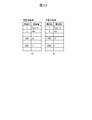
- FIG. 15A is a diagram showing an environment information list
- FIG. 15B is a diagram showing a similarity calculation result table which is a processing result.
- Overall configuration diagram of a log collection system according to the second embodiment The figure which shows the structure of a log indirect transmission apparatus and a log direct transmission apparatus The figure which shows the structure and stored information of summary log DB
- FIG. 1 is an overall configuration diagram of a log collection system 1.
- the log collection system 1 includes a single log collection device 200 and a plurality of log transmission devices 1100.
- the log collection device 200 and the plurality of log transmission devices 1100 are connected via a network 500.
- the network 500 is a wide area network such as the Internet.
- Log transmission device 1100 is, for example, a car navigation system (hereinafter referred to as “car navigation”) that can be mounted on a vehicle.
- the log collection device 200 is a server device that collects and analyzes logs output from the log transmission device 1100.
- the summary log has a smaller amount of information than the detailed log, but includes information that can be detected by the log collection device 200 that at least some failure has occurred.
- the detailed log includes more detailed information than the summary log, for example, information that contributes to the investigation of the cause of the failure and the solution of the failure.
- the outline of the first embodiment is as follows.
- the log collection device 200 detects an abnormality from the collected log information, the log collection device 200 transmits the log in which the abnormality is detected to the log transmission device 1100 (hereinafter referred to as “detected device to be detected”) in order to examine the details. Request a detailed log.
- the log collection device 200 requests a detailed log not only to the abnormality detection device but also to another log transmission device 1100 (hereinafter referred to as “alternative device”) having the same or similar environment as the abnormality detection device.
- the “environment” of the log transmission device 1100 is the state of the log transmission device 1100 including at least one of hardware and software.
- the log collection device 200 analyzes the details of the abnormality using the detailed log received from the alternative device. Details will be described below.
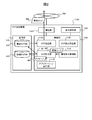
- FIG. 2 is a configuration diagram of the log transmission device 1100.
- the log transmission device 1100 includes a storage unit 1101 that stores an overview log DB 610 and a detailed log DB 620, a control unit 1102 that executes a series of processes of the log transmission device 1100, a display operation that displays an application execution screen and the like, and accepts user operations.
- a communication unit 1104 that performs communication with the unit 1103 and the log collection device 200.
- the control unit 1102 executes an application execution unit 1110, an environment change management unit 1120, a log output unit 1130, a log transmission unit 1140, by a CPU (not shown) executing a program stored in a ROM (not shown).
- the log request receiving unit 1150 operates.
- the display operation unit 1103 is, for example, a liquid crystal touch panel that includes an information presentation function for a user and an input function for receiving an operation from the user.
- the display operation unit 1103 presents information based on a command from the control unit 1102 and transmits a user input to the control unit 1102.
- the application execution unit 1110 executes one or more applications, for example, a destination search application, and outputs a message 601 that is an operation log of each application to the log output unit 1130.
- the message 601 includes a detailed log and a summary log.
- the application execution unit 1110 always outputs a detailed log when outputting a summary log, but may not output a summary log when outputting a detailed log.
- the environment change management unit 1120 monitors the change in the environment of the log transmission device 1100, and outputs the change in the environment every time the summary log is output by the application execution unit 1110 as an environment code 602 described in detail later. That is, when only the detailed log is output and the overview log is not output, the environment change management unit 1120 does not output the environment code 602. For example, when the environment of the log transmission device 1100 has a hardware configuration and a software configuration, addition / removal of hardware and software upgrade are detected by the environment change management unit 1120 as changes in the environment.
- the log output unit 1130 stores the detailed log output by the application execution unit 1110 in the detailed log DB 620.
- the log output unit 1130 stores the overview log output by the application execution unit 1110 and the environment code 602 output by the environment change management unit 1120 in the overview log DB 610.
- the summary log and the environment code 602 are collectively referred to as “summary set”.
- the configuration of the summary log DB 610 and the configuration of the detailed log DB 620 will be described later.
- the log transmission unit 1140 transmits the summary set 603 stored in the summary log DB 610 to the log collection device 200 every predetermined time period. Further, the log transmission unit 1140 transmits the detailed log stored in the detailed log DB 620 to the log collection device 200 based on the operation command from the log request reception unit 1150. When receiving a detailed log request from the log collection device 200, the log request reception unit 1150 outputs an operation command to the log transmission unit 1140, and causes the log transmission unit 1140 to transmit a detailed log to the log collection device 200.
- the application execution unit 1110, the environment change management unit 1120, the log output unit 1130, the log transmission unit 1140, and the log request reception unit 1150 may be configured as dedicated hardware.
- FIG. 3 is a configuration diagram of the log collection device 200.
- the log collection device 200 includes a storage unit 201 that stores collected logs, a control unit 202 that executes a series of processes of the log collection device 200, and a communication unit 203 that communicates with the log transmission device 1100.
- the control unit 202 operates as a failure detection unit 210, an environment information restoration unit 220, and a similar environment determination unit 230 when a CPU (not shown) executes a program stored in a ROM (not shown).
- the failure detection unit 210, the environment information restoration unit 220, and the similar environment determination unit 230 may be configured as dedicated hardware.
- the failure detection unit 210 detects the occurrence of a failure based on the summary log received from the log transmission device 1100, and transmits a detailed log request to the detected device and the alternative device.
- the detection of the failure occurrence is determined based on, for example, a status code of an HTTP response described later and a log correlation.
- Log correlation means that there is a response log for a request log and a called function log for a function call log.
- SMS Short Message Service
- the detailed log request can be transmitted by push-type notification.
- the environment information restoration unit 220 restores environment information representing the environment (state) of each log transmission device 1100 using the history of the environment code 602 included in the log information and the initial environment information 221.
- the initial environment information 221 is information indicating the initial environment of each log transmission apparatus 1100, that is, the environment at the time of product shipment.
- the initial environment information 221 is stored in the storage unit 201 of the log collection device 200, but in FIG. 3, it is described as being provided in the environment information restoration unit 220 for convenience.
- the similar environment determination unit 230 uses the environment information of each log transmission device 1100 restored by the environment information restoration unit 220 to determine another log transmission device 1100 whose environment is similar to the log transmission device 1100 in which the failure has occurred. . That is, the similar environment determination unit 230 specifies an alternative device for the detected abnormality detection device in which the failure detection unit 210 has detected a failure.
- FIG. 3 shows a configuration of the storage unit 201 when N log transmission devices 1100 are connected to the log collection device 200. That is, the storage unit 201 stores N summary DBs that store summary sets transmitted by the respective log transmission devices 1100, and N detail DBs that store detailed logs transmitted by the respective log transmission devices 1100. Is stored.
- the configuration of each summary DB is the same as the summary log DB 610 of the corresponding log transmission device 1100, and the configuration of each detail DB is the same as the detail log DB 620.
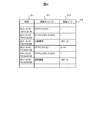
- FIG. 4 is a diagram showing the configuration of the summary log DB 610 and the stored information.
- the summary log DB 610 is composed of three fields: time 611, summary message 612, and environment code 613.
- time 611 the time when the summary log is output is stored.
- the summary log output from the application execution unit 1110 is stored in the field of the summary message 612.
- the environment code 602 output by the environment change management unit 1120 is stored. However, if there is no change in the environment and the environment code 613 is not output, “-” indicating that there is no corresponding information is stored.
- the log in the second row of the stored information shown in FIG. 4 includes request processing using HTTP (Hyper Text Transfer Protocol) at 3: 15: 32.765 on October 3, 2015 (hereinafter referred to as “HTTP request”). ”) Is performed. Further, “-” is stored in the field of the environment code 613, which indicates that there has been no change in the environment since the summary log was output immediately before.
- HTTP request Hyper Text Transfer Protocol
- HTTP response a response using HTTP (hereinafter referred to as “HTTP response”) is received at 3: 15: 33.423 on the same day, which is about 0.5 seconds later, and the status code is It shows that it was 200.
- the status code is a code indicating an outline of the HTTP response.
- the 200 series indicates that the process is normally performed, and the 400 series is not normally performed due to a problem caused by the client that requested the process. It shows that.
- the log on the fourth line indicates that the screen transition has been made in about 0.1 seconds, and that the environment of the log transmission device 1100 has changed and the environment code “1001-12” has been output. Has been.
- FIG. 5 is a diagram showing the configuration of the detailed log DB 620 and the stored information.
- the detail log DB 620 includes two fields, a time 621 and a detail message 622.
- the time 621 field stores the time when the detailed log is output.
- a detailed log output by the application execution unit 1110 is stored in the field of the detailed message 622.
- the log in the second line of the stored information shown in FIG. 5 indicates that an HTTP request was transmitted at 3: 15: 32.765 on October 3, 2015, and the method was “GET”. Has been. Further, the requested URL is specifically shown.
- the log on the third line indicates that an HTTP response with a status code of 200 is received and the meaning of the status code is “OK”, that is, the processing has been performed normally.
- the log on the fourth line indicates that the screen transition is performed and the screen ID of the transition destination is 12.
- the 5th and 7th lines indicate that some log entries are omitted.
- the log on the sixth line indicates that the software was updated from version 100 to version 101 at 5: 15: 33.423 seconds on the next day.
- the log on the eighth line indicates that an HTTP request was transmitted at 1: 0: 47.786 seconds on October 5, 2015, and the method was “GET”. Further, the requested URL is specifically shown.
- the log on the 10th line indicates that the screen transition is performed and the screen ID of the transition destination is 14. Comparing the summary log DB 610 shown in FIG. 4 and the detailed log DB 620 shown in FIG. 5, the three logs of the summary log DB 610 each of October 3 and October 5 are the logs in the second to fourth lines of the detail log DB 620. And 8th to 10th lines respectively. That is, at least a log relating to software update does not exist in the summary log DB 610.
- the environment code is a predetermined code that indicates a change in the environment of the log transmission device 1100, and is expressed by a combination of an environment ID that indicates the type of the changed environment and an environment value.
- the environment value is a value indicating the state after the change of the item represented by the environment ID.
- the environment ID is defined by environment ID definition information.
- the environment ID definition information is stored in the environment change management unit 1120 of the log transmission device 1100 and the environment information restoration unit 220 of the log collection device 200.
- FIG. 6 is a diagram illustrating an example of the environment ID definition information 630 indicating the meaning of the environment ID and the environment value.
- the environment ID “1” indicates that the hardware configuration has been changed
- the environment value attached to the environment ID is information for specifying the changed hardware configuration.
- the environment ID “2” indicates that the software version has been changed
- the environment value of the environment ID “2” indicates the software version after the change.
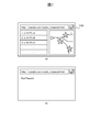
- FIG. 7 is a diagram illustrating an example of a screen displayed on the display operation unit 1103 by the application execution unit 1110 as a result of performing the HTTP request illustrated in FIGS. 4 and 5.
- 7A shows a result of accessing on October 3, 2015
- FIG. 7B shows a result of accessing on October 5, 2015.
- Both screens access the same URL “http://example.com/nearby-restaurant.html”. This URL searches for and displays a restaurant that exists in the vicinity of the position where the HTTP request is transmitted.
- the status code is 200, so the processing has been performed normally, so the display operation as shown in FIG. Part 1103 displays the location of the restaurant.
- an error occurs for some reason, as can be seen from the fact that the status code is 400 in FIGS. 4 and 5, and as shown in FIG. Is not displayed, and the contents of the error are displayed on the display operation unit 1103.
- FIG. 8 is a diagram showing a message 601 output by the application execution unit and an environment code 602 output by the environment change management unit 1120 when the execution screen of October 5, 2015 is displayed.
- the detailed log shown in FIG. 8A indicates that a request for the URL shown in the figure has been made by the HTTP GET method.
- the summary log shown in FIG. 8B indicates that an HTTP request has been made.
- An environment code 602 shown in FIG. 8C indicates that the environment code is “2-101”.
- “2” indicates that the environment ID is a software version
- “101” indicates that the environment value corresponding to the environment ID “2” is 101. . That is, the environment code 602 of “2-101” indicates that the software version has changed to “101” from when the overview log was output immediately before the current overview log is output.
- FIG. 9 is a flowchart showing the operation of the environment change management unit 1120 that generates the environment code 602.
- the environment change management unit 1120 executes a program whose operation is shown in FIG. 9 when the application execution unit 1110 outputs a summary log.
- An execution subject of each step described below is an environment change management unit 1120, that is, a CPU (not shown) provided in the log transmission device 1100.
- the environment change management unit 1120 first collects environment information of the log transmission device 1100 (step S1121). Environment information is collected by collecting information on items defined in the environment ID definition information 630. Next, the environmental change management unit 1120 compares each value of the collected environmental information with the environmental information that was previously collected and stored in the storage unit 1101 and determines whether there has been a change since the last time the information was collected. Judgment is made (step S1122). If it is determined that there is a change in the environment information, an environment code combining the changed environment ID and the environment value is generated (step S1123), and the changed environment information is stored in the storage unit 1101 (step S1124). The flowchart of 9 is finished. If it is determined in step S1122 that there is no change in the environment information, the flowchart of FIG.
- FIGS. 10A and 10B are diagrams showing a comparison of environment information when the HTTP request on October 5, 2015 shown in FIGS. 4 and 5 is performed, and FIG. The environmental information collected and stored in the storage unit 1101 is shown, and FIG. 10B shows the newly collected environmental information.
- the difference between FIG. 10A and FIG. 10B is the environment value of the environment ID “2” and the environment value after the change is “101”, so the environment code 602 is “2-101”.
- FIG. 11 is a flowchart showing the operation of the log output unit 1130 when the message 601 is received from the application execution unit 1110.
- the execution subject of each step described below is a log output unit 1130, that is, a CPU (not shown) included in the log transmission device 1100.
- the log output unit 1130 first stores the detailed log included in the message 601 in the detailed log DB 620 (step S1131). Next, it is determined whether or not a summary log is included in the message 601 (step S1132). When it is determined that the overview log is included, the overview log included in the message 601 and the environment code 602 received from the environment change management unit 1120 are stored in the overview log DB 610 (step S1133), and the flowchart of FIG. . If it is determined in step S1132 that the summary log is not included, the flowchart of FIG.
- FIG. 12 is a flowchart showing the operation of the log transmission unit 1140 when transmitting the contents of the summary log DB 610 and the detailed log DB 620 stored as described above to the log collection device 200.
- the execution subject of each step described below is a log transmission unit 1140, that is, a CPU (not shown) included in the log transmission device 1100.
- the log transmission unit 1140 performs the following transmission processing at regular time intervals such as every 5 minutes, immediately after the log transmission unit 1140 is started, or immediately before the operation is stopped by the operation stop command by the user. However, the transmission process may be executed based on a user operation input.
- the log transmission unit 1140 transmits the contents of the summary log DB 610 to the log collection device 200 (step S1141).
- the log transmission unit 1140 deletes the contents of the summary log DB 610 (step S1142).
- the log transmission unit 1140 checks whether a detailed log request is received from the log collection device 200 (step S1143). If it is determined that the detailed log request has been received, the contents of the detailed log DB 620 are transmitted to the log collection device 200 (step S1144), the contents of the detailed log DB 620 are deleted (step S1145), and the flowchart of FIG. To do.
- the flow chart of FIG. The above is the operation of the log transmission device 1100 when transmitting log information.
- the contents of the summary log DB and the detail log DB transmitted in this way are stored in the storage unit 201 of the log collection device 200.
- FIG. 13 is a flowchart showing the operation of the failure detection unit 210.
- the execution subject of each step described below is a failure detection unit 210, that is, a CPU (not shown) provided in the log collection device 200.
- the failure detection unit 210 executes the processing described below for each log of each log transmission device 1100 connected to the log collection device 200 every time a predetermined time, for example, 24 hours elapses.
- a predetermined time for example, 24 hours elapses.
- the first overview DB 640 and the first detail DB 650 corresponding to a certain log transmission device 1100 will be described as an example.
- the failure detection unit 210 refers to the first summary DB 640 stored in the storage unit 201 and acquires summary logs for a predetermined period, for example, the latest 24 hours (step S211). Next, it is confirmed whether or not any error is included in the acquired summary log (step S212). The presence / absence of an abnormality can be determined as having no abnormality if the status code of the HTTP response is in the 200 range, for example, and can be determined to be abnormal if it is other than the 200 range. If the failure detection unit 210 determines that an abnormality is included, the failure detection unit 210 restores environment information described below (step S213), and identifies an alternative device based on determination of a similar environment described later (step S214).
- the failure detection unit 210 transmits a detailed log request to the log transmission device 1100 that has transmitted the log in which the abnormality is detected, that is, the abnormality detection device and the alternative device (step S215), and ends the flowchart of FIG.
- the failure detection unit 210 determines that no abnormality is included, the flowchart of FIG.
- Environment information restoration processing by the failure detection unit 210 is performed in order to compare the environments (states) of the log transmission devices 1100 when an abnormality is detected in the summary log acquired from any of the log transmission devices 1100. This is processing for restoring environment information of the log transmission device 1100.
- the initial environment information 221 of the processing target log transmission apparatus 1100 is updated, that is, overwritten with the environment code 602 included in the outline set stored in the outline DB corresponding to the log transmission apparatus 1100.
- the description of the environment code 602 is prioritized, and the description related to only one of the environment IDs is directly restored as environment information.
- this process is performed in order for all log transmission apparatuses 1100 as processing targets.
- FIG. 14 is a diagram showing an example of restoration processing of environment information.
- the outline information shown in FIG. 4 is obtained, and the environment information restoration processing will be described by taking as an example a case where the failure detection unit 210 detects an abnormality in the log of 10: 00: 48.525 on October 5.
- the initial environment information 221 includes information corresponding to the environment codes “1-TypeA” and “2-100”, and the environment code up to the time when the abnormality included in the summary DB is detected.
- 602 is “1001-12” and “2-101”
- the environment information is restored as follows. That is, environment information including “1-Type A”, “2-101”, and “1001-12” is restored. Since the environment value of environment code “1” is not included in the overview DB, it remains the initial value, the environment value of environment code “2” is changed to “101”, and the environment value of environment code “1001” is This is because it is changed to “12”.
- the determination process of the similar environment by the failure detection unit 210 is performed as follows using the result of the environment information restoration process in step S213, for example. That is, using the weight of each item of the environment ID that is set in advance, the environment values of the detected abnormality apparatus and the environment ID match for all log transmission apparatuses 1100 other than the detected abnormality apparatus that detected an abnormality. The sum of the weights of items to be calculated is calculated as the similarity. Then, an alternative device is determined based on the degree of similarity. The alternative device may be one log transmission device 1100 having the highest similarity, or may be a predetermined number of log transmission devices 1100 having a higher similarity.
- FIG. 15 is a diagram illustrating an example of the similar environment determination process
- FIG. 15A is a diagram illustrating an environment information list 706 that is a list of environment information that is a premise of the similar environment determination process.
- there are four log transmission apparatuses that is, first to fourth log transmission apparatuses, and the first log transmission apparatus is an abnormality detection apparatus.
- the environment information of each log transmission device is different, and the environment value is the same as or different from the first log transmission device for each environment ID.
- the “weight” field shown in FIG. 15B indicates the weight for each preset environment ID.
- the weight of that environment ID is added.
- the value of the environment ID “1” in the similarity calculation result table 707 is the weight value “10”.
- the value of the environment ID “2” also matches the first log transmission device.
- the value of the environment ID “2” is “15” which is the weight value.
- the value of the environment ID “1001” in the similarity calculation result table 707 is zero. Therefore, the total weight of the second log transmission device, that is, the similarity is “25”. However, only the total value of the values of the environment IDs “1”, “2”, and “1001” is shown here. Similarly, the similarity of the third log transmission device is “15”, and the similarity of the fourth log transmission device is “16”.
- the second log transmitting device when only the device having the highest similarity is used as the substitute device, only the second log transmitting device is used as the substitute device, and when the upper two devices having high similarity are used as the substitute devices, the second log transmitting device and the fourth log The transmission device becomes an alternative device.
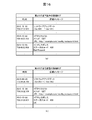
- FIG. 16 is a diagram showing the detailed logs received from these alternative devices when the alternative devices are the top two log transmission devices 1100 with high similarity, that is, the second log transmission device and the fourth log transmission device. .
- FIG. 16 shows only the software update log and the access log to the above-mentioned URL. Since the log collection device 200 can obtain the detailed log of the alternative device shown in FIG. 16 in addition to the detailed log of the detected device, it is highly possible that an error has occurred when the software is updated to version 101. Can be guessed. By collecting logs from other log transmission apparatuses having similar failure occurrence environments in this way, it becomes possible to start investigation of failure occurrence conditions and reproduction procedures.
- the log transmission device 1100 is connected to the log collection device 200 via the network 500.
- the log transmission device 1100 includes an application execution unit 1110 that outputs a summary log, an environment change management unit 1120 that generates an environment code 602 that is information indicating a change in the state of the log transmission device 1100, and logs the summary log and the environment code.
- the environment change management unit 1120 includes a log transmission unit 1140 that transmits to the collection device 200.
- the environment change management unit 1120 changes the state of the log transmission device 1100 from when the application execution unit 1110 outputs the summary log to the current output, that is, the environment.
- An environment code 602 indicating a change is generated.
- the log transmission device 1100 transmits not only the summary log but also the environment code 602 indicating the environment when this summary log is generated, the log collection device 200 that has received the log transmission device 1100 has detailed generation conditions. And the reproduction procedure can be expressed.
- the environment code 602 is so-called difference information of the environment information of the log transmission device 1100, so that although it is detailed information, a storage area and a communication amount necessary for recording are reduced more than environment information itself.
- the log transmission device 1100 can provide an overview log necessary for detecting a failure and an environment code 602 necessary for reproducing a state at the time of occurrence of an abnormality, the log collection device 200 receives a detailed log from the log transmission device 1100 in which the failure has occurred. Even when the error cannot be obtained, the cause of the failure can be investigated using the logs of other log transmission apparatuses 1100 having similar states at the time of occurrence of the abnormality.
- a log request receiving unit that transmits a detailed log including more detailed information than the summary log, that is, a communication unit 1104 is provided. Therefore, during normal times, an overview log with a small amount of information that can be processed with a limited communication bandwidth and low power consumption is transmitted, and a detail log for investigating details is transmitted in response to a request from the log collection device 200 be able to.
- the environment code 602 includes an item code indicating an item in a changed state, that is, an environment ID, and a value code indicating a value after the change of the item represented by the item code, that is, an environment value. Therefore, the change in the environment of the log transmission device 1100 can be expressed succinctly.
- the log collection system 1 includes a log transmission device 1100 and a log collection device 200 connected via a network 500.
- the log transmission device 1100 includes an application execution unit 1110 that outputs a log, an environment change management unit 1120 that generates an environment code 602 that is information indicating a change in the state of the log transmission device 1100, and collects a summary log and an environment code.
- the environment change management unit 1120 includes a log transmission unit 1140 that transmits to the device 200.
- the environment change management unit 1120 changes the state of the log transmission device 1100 from when the application execution unit 1110 outputs the summary log to the current output, that is, changes in the environment.
- An environment code 602 is generated.
- the log collection device 200 analyzes the summary log received from the log transmission device 1100 and detects a failure, and uses the failure detection unit 210 that detects a failure and the environment code 602 received from the log transmission device 1100, that is, the status of the log transmission device 1100, that is, the environment
- the environment information restoring unit 220 that restores information and the environment information restoring unit 220 are the same as or similar to the abnormality detection device that is the log transmission device 1100 that has transmitted the summary log in which the failure detection unit 210 has detected the failure.
- a similar environment determination unit 230 that determines the log transmission device 1100 of The log collection device 200 analyzes the received summary log to detect a failure, and determines another log transmission device 1100 that is the same as or similar to the detected abnormality detection device. The cause can be investigated in the range of the summary log.
- the log collection device 200 sends a detailed log command to another log transmission device 1100 having the same or similar environment as the abnormality detection device that is the log transmission device that has transmitted the summary log in which the failure detection unit 210 has detected the failure.
- the log request unit for transmitting the error that is, the failure detection unit 210 is provided.
- the log transmission device 1100 includes a log request reception unit 1150 that transmits a detailed log including more detailed information than the summary log. Therefore, the log collection device 200 can acquire a detailed log of another log transmission device 1100 whose state is the same as or similar to that of the abnormality detection device. As a result, the log collection device 200 can investigate the influence of environmental differences on failures.
- the log transmission device 1100 may request the user to consent to transmit the detailed log, and may transmit the detailed log only when the user's consent is obtained.
- the means for requesting consent to transmit the detailed log to the user may make a voice inquiry using a voice output unit (not shown), or may make a display inquiry using the display operation unit 1103. Further, an unsent summary log may be transmitted together with the detailed log request.
- FIG. 17 is a diagram illustrating an example in which a display inquiry is performed using the display operation unit 1103.
- the detailed log is transmitted when “Yes” is selected by the user, and the detailed log is not transmitted when “No” is selected by the user.
- FIG. 18 is a flowchart showing the operation of the log request receiving unit 1150 in the first modification.
- the execution subject of each step described below is a log request reception unit 1150, that is, a CPU (not shown) of the log transmission device 1100.
- step S1151 an inquiry is made to the user of the log transmission device 1100 to confirm whether transmission is possible, that is, to request permission for transmission.
- step S1152 it is determined whether or not a transmission OK response, that is, consent has been obtained. If it is determined that a positive response has been obtained, the process proceeds to step S1153, and an outline set is acquired from the outline log DB 610 and transmitted. Then, the detailed log is acquired from the detailed log DB 1155 and transmitted, and the flowchart of FIG. 18 is ended. If it is determined in step S1152 that a negative response has been obtained, the flowchart of FIG.
- the log transmission device 1100 transmits a message to that effect to the log collection device 200, and the log collection device 200 that has received the message transmits it to the other log transmission device 1100.
- a detailed log request may be sent to.
- the log transmission device 1100 may confirm whether or not the detailed log can be transmitted in advance before receiving the detailed log request, and may store the result. In this case, the operation is performed based on the stored result without performing the display shown in FIG.
- the environment code 602 includes the environment ID and the environment value.
- the environment code 602 may further include a base ID.
- the base ID is a reference code indicating the state of the log transmitting apparatus 1100 serving as a reference, and defines initial values of corresponding environmental values for several environment IDs of the log transmitting apparatus 1100.
- the base ID value and the initial value of the environment value for each environment ID in the corresponding environment information are defined by the base ID definition table 710.
- the base ID definition table 710 is stored in both the log collection device 200 and the log transmission device 1100.
- FIG. 19 is a diagram illustrating an example of the base ID definition table 710. As shown in FIG.
- the base ID definition table 710 defines a combination of an environment ID and an environment value as an initial value for each base ID.
- the base ID definition table 710 includes only two environment IDs. However, three or more environment IDs may be included, and at least one environment ID may be included.
- the environment change management unit 1120 in Modification 2 When the environment change management unit 1120 in Modification 2 generates the environment code 602 for the first time, the environment ID indicating the difference between the environment information of the log transmission device 1100 indicated by the reference code and the environment information of the current log transmission device 1100 is shown. And generate environment values.
- the environment change management unit 1120 When the environment change management unit 1120 generates the environment code 602 for the second time or later, the environment ID indicating the change in the state of the log transmission device 1100 from when the application execution unit 1110 outputs the summary log last time to this time output And generate environment values.
- the environment information when the log transmission device 1100 first generates the environment code 602 is “1-Type A, 2-101”, and “01” is used as the base ID
- “01” is set as the environment code 602. -2-101 "is output.
- the difference from the environment information represented by the base ID “01” is that the environment value is the environment ID “2”.
- the environment information when the environment code 602 is generated next is “1-TypeB, 2-100”, “01-1-TypeB” is output as the environment code 602. This is because the change in the environment information since the previous generation of the environment code 602 is “1-TypeB”.
- the environment information restoration unit 220 restores the environment information of the log transmission device 1100 using the base ID definition table 710 provided in the log collection device 200 and the received environment code 602. According to the second modification, since the environment information of the log transmission device 1100 is expressed by a difference from the environment information represented by the base ID, detailed environment information can be restored while reducing the amount of information recorded as a log. .
- the failure detection unit 210 of the log collection device 200 when the failure detection unit 210 of the log collection device 200 detects a failure, it transmits a detailed log request to the detected abnormality detection device and the alternative device.
- the detailed log request may be transmitted to the alternative device only when the detailed log cannot be obtained from the detected device.
- the case where the detailed log cannot be obtained from the abnormality detection device means that the log collection device 200 is subject to the reason that the abnormality detection device is turned off at the time when the log collection device 200 detects a failure. This is a case where communication with the abnormality detection apparatus cannot be performed and a detailed log request cannot be transmitted.
- the log collection device 200 can transmit the detailed log request but the detailed log is not transmitted from the abnormality detection device within a predetermined time, for example, within 10 seconds, is included in the case where the detailed log cannot be obtained.
- the power may be turned on from a remote place by using a technique such as Wake On LAN.
- Modification 4 In the first embodiment described above, when the occurrence of a failure is detected, the detailed log request is transmitted to the log transmission device 1100. However, the environment information in which the failure occurs using only the summary log without transmitting the detailed log request. You may specify. For example, it is possible to determine whether or not a failure similar to that of the abnormality detection device is found from the overview log of the alternative device, and specify the environment information in which the failure occurs by making this determination for a plurality of alternative devices. it can.
- the application execution unit 1110 outputs a detailed log and a summary log.
- the log output unit 1130 may generate a summary log based on the detailed log output by the application execution unit 1110. For example, a summary log template corresponding to the detailed log is prepared in advance, and the log output unit 1130 generates the summary log only when the detailed log corresponding to the prepared pattern is output.
- the environment change management unit 1120 outputs the environment code 602 only when the log output unit 1130 generates a summary log.
- the “environment” of the log transmission device 1100 indicates the configuration of at least one of hardware and software.
- the resource of the log transmission device 1100 that is, the load factor of the CPU (not shown), the free capacity of the storage area (not shown), the usage amount of the RAM (not shown), etc. may be added to the “environment” of the log transmission device 1100 .
- information that may contribute to the investigation of the cause of the failure such as the temperature and operating time of the log transmission device 1100 may be further added to the “environment” of the log transmission device 1100.
- log direct transmission device a log transmission device provided with a direct communication means to the log collection device 200 and a direct communication means to the log collection device 200. It differs from the first embodiment in that it is used in combination with a non-log transmission device (hereinafter referred to as “log indirect transmission device”).
- FIG. 20 is an overall configuration diagram of a log collection system 1A according to the second embodiment.
- the log collection system 1A includes a single log collection device 200, a plurality of log indirect transmission devices 1200, and a plurality of log direct transmission devices 1300.
- the log direct transmission device 1300 is connected to the log collection device 200 via the network 500.
- the log indirect transmission device 1200 is connected to the log collection device 200 via the log direct transmission device 1300 and the network 500.
- the log indirect transmission device 1200 is a car navigation system that can be mounted on a vehicle, for example.
- the log direct transmission device 1300 is, for example, a mobile phone, a smartphone, or a dedicated communication module. Since the configuration and operation of the log collection device 200 are the same as those in the first embodiment, description thereof will be omitted.
- FIG. 21 is a diagram illustrating a configuration of the log indirect transmission device 1200 and the log direct transmission device 1300.
- the configurations and operations of the log indirect transmission device 1200 and the log direct transmission device 1300 are the same as those of the log transmission device 1100 according to the first embodiment unless otherwise described. That is, as described in the first embodiment, the log indirect transmission device 1200 transmits the outline set 623 for each predetermined time period.
- the summary set 623 is transmitted to the log collection device 200 with the environment code 1632 of the log direct transmission device 1300 added as will be described later.
- the log indirect transmission device 1200 is different from the log transmission device 1100 according to the first embodiment in that the communication destination of the communication unit 1204 is limited.
- the communication unit 1204 communicates with the short-range communication unit 1306 of the log direct transmission device 1300.
- the communication unit 1204 and the short-range communication unit 1306 perform communication using Bluetooth (registered trademark), Wi-Fi (registered trademark), or the like. That is, the log indirect transmission device 1200 outputs the summary log output from the application execution unit 1110 and the environment code 1622 output from the environment change management unit 1220 to the log direct transmission device 1300 as a summary set 623.
- the log direct transmission device 1300 is different from the log transmission device 1100 according to the first embodiment in that it further includes a short-range communication unit 1306.
- the application executed by the application execution unit 1310 includes a transfer application described later.
- the communication unit 1304 supports a plurality of communication standards, and a change in the communication standard to be used is reflected in the environment code 1632.
- the environment ID “2001” indicates that the communication standard used by the communication unit 1304 has changed. If the value is “zero”, it indicates that the communication has been switched to 3G, and if the value is “1”. It shows that it switched to LTE.
- the short-range communication unit 1306 communicates with the log indirect transmission device 1200 using Bluetooth (registered trademark), Wi-Fi (registered trademark), or the like.
- the short-range communication unit 1306 is switched on and off based on a user instruction or the like.
- the operation state of the short-range communication unit 1306 is switched off, communication with the log indirect transmission device 1200 becomes impossible, but the power consumption of the log direct transmission device 1300 is suppressed.
- the operation state of the short-range communication unit 1306 is switched on, communication with the log indirect transmission device 1200 becomes possible, but the power consumption of the log direct transmission device 1300 increases.
- the change in the operating state of the short-range communication unit 1306 is reflected in the environment code 1632. For example, the environment ID “2002” indicates that the operating state of the short-range communication unit 1306 has changed. If the value is “zero”, it indicates that it has been switched off. If the value is “1”, Indicates that it was switched on.
- the transfer application acquires the summary set 623 output by the log indirect transmission device 1200 and outputs the contents of the summary set 623 to the log output unit 1330 as the summary log of the application.
- the log direct transmission device 1300 generates a summary set by attaching the environment code 1632 output by the environment change management unit 1320 to the summary log output by the application execution unit 1310. That is, when the application execution unit 1210 of the log indirect transmission device 1200 outputs a summary log, the environment code 1622 of the log indirect transmission device 1200 and the environment code 1632 of the log direct transmission device 1300 are added to form a summary set 633.
- the application executed by the application execution unit 1310 is not limited to the transfer application that processes the summary set 623, the summary set 633 output by the log direct transmission device 1300 does not include the environment code 1622 of the log indirect transmission device 1200. There is also.
- the log request reception unit 1350 When receiving the detailed log request from the log collection device 200, the log request reception unit 1350 not only transmits the detailed log stored in the detailed log DB 620B to the log collection device 200 but also transmits the detailed log request to the log indirect transmission device 1200. To do. In response to this request, the detailed log transmitted from the log indirect transmission device 1200 is also transmitted to the log collection device 200. However, when communication with the log indirect transmission device 1200 cannot be performed, such as when the operation state of the short-range communication unit 1306 is OFF, the detailed log request is not transmitted to the log indirect transmission device 1200.
- FIG. 22 is a diagram showing a configuration of the summary log DB 610B and stored information.
- FIG. 22 shows a log based on the operation of the transfer application, that is, a log based on the summary set 623 output by the log indirect transmission device 1200.
- an environment code 1622 generated by the log indirect transmission device 1200 and an environment code 1632 generated by the log direct transmission device 1300 are appended to the summary message output by the application execution unit 1210 of the log indirect transmission device 1200.
- the communication code used by the communication unit 1304 of the environment code “2001-1”, that is, the log direct transmission device 1300 is switched to LTE from when the HTTP response is obtained from the log on the fifth line until the screen transition is performed. It is shown that. Therefore, the log collection device 200 can grasp not only the log indirect transmission device 1200 but also environment information of the log direct transmission device 1300.
- the log direct transmission device 1300 includes a short-range communication unit 1306 that communicates with another log transmission device, that is, the log indirect transmission device 1200.
- the application execution unit 1310 outputs the overview log received from the log indirect transmission device 1200 and the environment code 1622 received from the log indirect transmission device 1200 as the overview log. Therefore, the log direct transmission device 1300 transmits to the log collection device 200 a summary set 633 obtained by adding the environment code 1632 output from the environment change management unit 1320 to the summary log and environment code 1622 received from the log indirect transmission device 1200. Accordingly, the log collection device 200 can restore not only the log indirect transmission device 1200 but also the environment information of the log direct transmission device 1300.
- the log direct transmission device 1300 Upon receiving the detailed log command from the log collection device 200, the log direct transmission device 1300 outputs the detailed log command to the log indirect transmission device 1200, and the detailed log received from the log indirect transmission device 1200 is output to the log collection device 200.
- a log request receiving unit 1350 for transmitting to Therefore, the log collection device 200 can acquire detailed logs of not only the log direct transmission device 1300 but also the log indirect transmission device 1200.
- the operation state of the short-range communication unit 1306 can be switched on or off, and the environmental code 1632 output from the environment change management unit 1320 reflects the switching of the operation state of the short-range communication unit. Therefore, when a problem occurs due to the fact that the operation state of the short-range communication unit 1306 has been switched off, the cause can be easily determined.
- the log indirect transmission device 1200 may transmit the detailed log to the log direct transmission device 1300 without receiving the detailed log request.
- the timing at which the log indirect transmission device 1200 transmits the detailed log to the log direct transmission device 1300 may be every predetermined time period or every time the detailed log is output from the application execution unit 1210.
- the log direct transmission device 1300 receives the detailed log from the log indirect transmission device 1200 at a timing when the detailed log request is not received, the log direct transmission device 1300 does not transmit the log to the log collection device 200 but accumulates it in the detailed log DB 620B.
- the detailed log request is received from the log collection device 200, the detailed log is transmitted to the log collection device 200.
- the log collection device 200 when the log collection device 200 transmits a detailed log request, even if the log indirect transmission device 1200 cannot communicate with the log direct transmission device 1300, the log collection device 200 logs the log indirect transmission device 1200. A detailed log that has already been transmitted to the direct transmission device 1300 can be acquired.
- This modification is particularly effective when the log indirect transmission device 1200 and the log direct transmission device 1300 are not always used in the same place, or when the log indirect transmission device 1200 is frequently turned off. It is. Specifically, this is particularly effective when the log indirect transmission device 1200 is a car navigation system mounted on a vehicle and the log direct transmission device 1300 is a mobile terminal.
- the log indirect transmission device 1200 may request permission to transmit the detailed log to the user, and may transmit the detailed log only when the user's consent is obtained.
- an inquiry may be displayed on the display operation unit 1203 included in the log indirect transmission device 1200, or the display operation unit included in the log direct transmission device 1300.
- An inquiry may be displayed at 1303.
- an unsent summary log may be sent together with the detailed log request.
- the program is stored in a ROM (not shown), the program may be stored in a nonvolatile memory (not shown).
- the log transmission device 1100 may include an input / output interface (not shown), and the program may be read from another device via the input / output interface and a medium that can be used by the log transmission device 1100 when necessary.
- the medium refers to, for example, a storage medium that can be attached to and detached from the input / output interface, or a communication medium, that is, a wired, wireless, or optical network, or a carrier wave or digital signal that propagates through the network.
- part or all of the functions realized by the program may be realized by a hardware circuit or FPGA.
Landscapes
- Engineering & Computer Science (AREA)
- Theoretical Computer Science (AREA)
- General Engineering & Computer Science (AREA)
- Physics & Mathematics (AREA)
- Quality & Reliability (AREA)
- General Physics & Mathematics (AREA)
- Computing Systems (AREA)
- Computer Hardware Design (AREA)
- Health & Medical Sciences (AREA)
- Biomedical Technology (AREA)
- Mathematical Physics (AREA)
- Debugging And Monitoring (AREA)
Abstract
ログ送信装置は、通信網を介してログ収集装置と接続されるログ送信装置であって、ログを出力するアプリケーション実行部と、当該ログ送信装置の状態の変化を示す情報である環境コードを生成する環境変化管理部と、ログおよび環境コードをログ収集装置に送信する送信部とを備え、環境変化管理部は、アプリケーション実行部がログを前回出力してから今回出力するまでの状態の変化を示す環境コードを生成する。
Description
本発明は、ログ送信装置、およびログ収集システムに関する。
機器に何らかの障害が発生した場合に、その機器のログ情報を参照して障害原因を調査することが多い。この際に、障害が発生した機器のログ情報だけでは情報が不足していて有効な調査を行えない場合があるため、関連する他の機器のログ情報もあわせて収集して調査することが行われている。
特許文献1には、ログ収集対象の機器および収集するログを操作者に選択させるグラフィカルユーザインタフェースと、前記グラフィカルユーザインタフェース上で選択されたログに関連する他のログを判別し、前記関連する他のログを前記グラフィカルユーザインタフェース上で選択状態にする組合せ管理手段とを備えたことを特徴とするログ収集装置が開示されている。
特許文献1には、ログ収集対象の機器および収集するログを操作者に選択させるグラフィカルユーザインタフェースと、前記グラフィカルユーザインタフェース上で選択されたログに関連する他のログを判別し、前記関連する他のログを前記グラフィカルユーザインタフェース上で選択状態にする組合せ管理手段とを備えたことを特徴とするログ収集装置が開示されている。
特許文献1に記載されている発明では、障害が発生した機器から詳細なログが得られない場合に障害原因の調査が困難である。
本発明の第1の態様によるログ送信装置は、通信網を介してログ収集装置と接続されるログ送信装置であって、ログを出力するアプリケーション実行部と、当該ログ送信装置の状態の変化を示す情報である環境コードを生成する環境変化管理部と、前記ログおよび前記環境コードを前記ログ収集装置に送信する送信部とを備え、前記環境変化管理部は、前記アプリケーション実行部が前記ログを前回出力してから今回出力するまでの状態の変化を示す前記環境コードを生成する。
本発明の第2の態様によるログ収集システムは、通信網を介して接続されるログ送信装置、およびログ収集装置を含むログ収集システムであって、前記ログ送信装置は、ログを出力するアプリケーション部と、当該ログ送信装置の状態の変化を示す情報である環境コードを生成する環境変化管理部と、前記ログおよび前記環境コードを前記ログ収集装置に送信する送信部とを備え、前記環境変化管理部は、前記アプリケーション部が前記ログを前回出力してから今回出力するまでの状態の変化を示す前記環境コードを生成し、前記ログ収集装置は、前記ログ送信装置から受信した前記ログを解析し障害を検知する障害検知部と、前記ログ送信装置から受信した前記環境コードを用いて状態が同一または類似する他のログ送信装置を判定する類似環境判定部と、を備える。
本発明の第2の態様によるログ収集システムは、通信網を介して接続されるログ送信装置、およびログ収集装置を含むログ収集システムであって、前記ログ送信装置は、ログを出力するアプリケーション部と、当該ログ送信装置の状態の変化を示す情報である環境コードを生成する環境変化管理部と、前記ログおよび前記環境コードを前記ログ収集装置に送信する送信部とを備え、前記環境変化管理部は、前記アプリケーション部が前記ログを前回出力してから今回出力するまでの状態の変化を示す前記環境コードを生成し、前記ログ収集装置は、前記ログ送信装置から受信した前記ログを解析し障害を検知する障害検知部と、前記ログ送信装置から受信した前記環境コードを用いて状態が同一または類似する他のログ送信装置を判定する類似環境判定部と、を備える。
本発明によれば、障害の検出と異常発生時の状態の再現に必要な情報が得られるので、障害が発生した機器から詳細なログが得られない場合でも、異常発生時の状態が類似する他の機器のログを用いて障害原因の調査ができる。
(第1の実施の形態)
以下、図1~図16を参照して、ログ送信装置およびログ収集システムの第1の実施の形態を説明する。
以下、図1~図16を参照して、ログ送信装置およびログ収集システムの第1の実施の形態を説明する。
(全体構成と発明の概要)
図1は、ログ収集システム1の全体構成図である。ログ収集システム1は、1台のログ収集装置200と、複数のログ送信装置1100とから構成される。ログ収集装置200と複数のログ送信装置1100とは、ネットワーク500を介して接続される。ネットワーク500は広域のネットワーク網、たとえばインターネットである。ログ送信装置1100は、たとえば車両に搭載可能なカーナビゲーションシステム(以下、「カーナビ」と呼ぶ)である。ログ収集装置200はログ送信装置1100が出力するログを収集し解析するサーバ装置である。
図1は、ログ収集システム1の全体構成図である。ログ収集システム1は、1台のログ収集装置200と、複数のログ送信装置1100とから構成される。ログ収集装置200と複数のログ送信装置1100とは、ネットワーク500を介して接続される。ネットワーク500は広域のネットワーク網、たとえばインターネットである。ログ送信装置1100は、たとえば車両に搭載可能なカーナビゲーションシステム(以下、「カーナビ」と呼ぶ)である。ログ収集装置200はログ送信装置1100が出力するログを収集し解析するサーバ装置である。
ログ送信装置1100が送信するログには、詳細ログと概要ログの2種類がある。概要ログは、詳細ログよりも情報量が少ないが、少なくとも何らかの障害が発生したことがログ収集装置200により検出可能な情報が含まれる。詳細ログには、概要ログよりも詳細な情報、たとえば障害の原因究明や障害の解決に資する情報が含まれる。
第1の実施の形態の概要は以下のとおりである。ログ収集装置200は、収集したログ情報から異常を検出すると、その詳細を検討するために、異常が検出されたログを送信したログ送信装置1100(以下、「被異常検出装置」と呼ぶ)に詳細ログを要求する。しかし、ログ収集装置200が詳細ログの要求を送信した際に、被異常検出装置の電源がオフの状態である場合など、詳細ログの送信が不可能な場合が想定される。そのためログ収集装置200は、被異常検出装置だけでなく、被異常検出装置と環境が同一または類似の他のログ送信装置1100(以下、「代替装置」と呼ぶ)に詳細ログを要求する。ただしログ送信装置1100の「環境」とは、ハードウエアおよびソフトウエアの少なくとも一方の構成を含むログ送信装置1100の状態である。ログ収集装置200は、代替装置から受信する詳細ログを用いて異常の詳細を解析する。以下、詳細を説明する。
(ログ送信装置の構成)
図2は、ログ送信装置1100の構成図である。ログ送信装置1100は、概要ログDB610および詳細ログDB620を格納する記憶部1101、ログ送信装置1100の一連の処理を実行する制御部1102、アプリケーションの実行画面等を表示しユーザーの操作を受け付ける表示操作部1103、およびログ収集装置200との通信を行う通信部1104を備える。制御部1102は、不図示のROMに格納されたプログラムを不図示のCPUが実行することにより、アプリケーション実行部1110と、環境変化管理部1120と、ログ出力部1130と、ログ送信部1140と、ログ要求受信部1150として動作する。表示操作部1103は、ユーザへの情報提示機能とユーザからの操作を受け付ける入力機能とを備える、たとえば液晶タッチパネルである。表示操作部1103は、制御部1102の指令に基づき情報を提示し、ユーザの入力を制御部1102に伝達する。
図2は、ログ送信装置1100の構成図である。ログ送信装置1100は、概要ログDB610および詳細ログDB620を格納する記憶部1101、ログ送信装置1100の一連の処理を実行する制御部1102、アプリケーションの実行画面等を表示しユーザーの操作を受け付ける表示操作部1103、およびログ収集装置200との通信を行う通信部1104を備える。制御部1102は、不図示のROMに格納されたプログラムを不図示のCPUが実行することにより、アプリケーション実行部1110と、環境変化管理部1120と、ログ出力部1130と、ログ送信部1140と、ログ要求受信部1150として動作する。表示操作部1103は、ユーザへの情報提示機能とユーザからの操作を受け付ける入力機能とを備える、たとえば液晶タッチパネルである。表示操作部1103は、制御部1102の指令に基づき情報を提示し、ユーザの入力を制御部1102に伝達する。
アプリケーション実行部1110は、1以上のアプリケーション、たとえば目的地検索のアプリケーションを実行し、各アプリケーションの動作ログであるメッセージ601をログ出力部1130に出力する。メッセージ601には、詳細ログと概要ログとが含まれる。アプリケーション実行部1110は、概要ログを出力する場合には詳細ログを必ず出力するが、詳細ログを出力する場合に概要ログを出力しないこともある。
環境変化管理部1120は、ログ送信装置1100の環境の変化を監視しており、アプリケーション実行部1110により概要ログが出力される毎の環境の変化を、後に詳述する環境コード602として出力する。すなわち、詳細ログのみが出力され概要ログが出力されない場合は、環境変化管理部1120は環境コード602を出力しない。たとえば、ログ送信装置1100の環境がハードウエア構成およびソフトウエア構成である場合に、ハードウエアの追加や取り外し、ソフトウエアのバージョンアップは環境の変化として環境変化管理部1120に検出される。
ログ出力部1130は、アプリケーション実行部1110が出力する詳細ログを詳細ログDB620に格納する。ログ出力部1130は、アプリケーション実行部1110が出力する概要ログ、および環境変化管理部1120が出力する環境コード602を概要ログDB610に格納する。以下では、概要ログと環境コード602をあわせて「概要セット」と呼ぶ。概要ログDB610の構成、および詳細ログDB620の構成は後述する。
ログ送信部1140は、あらかじめ定められた時間周期ごとに概要ログDB610に格納された概要セット603をログ収集装置200に送信する。またログ送信部1140は、ログ要求受信部1150からの動作指令に基づき詳細ログDB620に格納された詳細ログをログ収集装置200に送信する。
ログ要求受信部1150は、ログ収集装置200から詳細ログ要求を受信すると、ログ送信部1140に動作指令を出力し、ログ送信部1140にログ収集装置200へ詳細ログを送信させる。
なお、アプリケーション実行部1110、環境変化管理部1120、ログ出力部1130、ログ送信部1140、およびログ要求受信部1150は、専用のハードウエアとして実現する構成としても良い。
ログ要求受信部1150は、ログ収集装置200から詳細ログ要求を受信すると、ログ送信部1140に動作指令を出力し、ログ送信部1140にログ収集装置200へ詳細ログを送信させる。
なお、アプリケーション実行部1110、環境変化管理部1120、ログ出力部1130、ログ送信部1140、およびログ要求受信部1150は、専用のハードウエアとして実現する構成としても良い。
(ログ収集装置の構成)
図3は、ログ収集装置200の構成図である。ログ収集装置200は、収集したログが格納される記憶部201と、ログ収集装置200の一連の処理を実行する制御部202と、ログ送信装置1100との通信を行う通信部203とを備える。制御部202は、不図示のROMに格納されたプログラムを不図示のCPUが実行することにより、障害検知部210と、環境情報復元部220と、類似環境判定部230として動作する。なお、障害検知部210、環境情報復元部220、類似環境判定部230は、専用のハードウエアとして実現する構成としても良い。
図3は、ログ収集装置200の構成図である。ログ収集装置200は、収集したログが格納される記憶部201と、ログ収集装置200の一連の処理を実行する制御部202と、ログ送信装置1100との通信を行う通信部203とを備える。制御部202は、不図示のROMに格納されたプログラムを不図示のCPUが実行することにより、障害検知部210と、環境情報復元部220と、類似環境判定部230として動作する。なお、障害検知部210、環境情報復元部220、類似環境判定部230は、専用のハードウエアとして実現する構成としても良い。
障害検知部210は、ログ送信装置1100から受信した概要ログに基づき障害の発生を検知し、被異常検出装置および代替装置に詳細ログ要求を送信する。障害発生の検知は、たとえば後述するHTTPレスポンスのステータスコードや、ログの相関関係に基づき判断される。ログの相関関係とは、リクエストのログに対するレスポンスのログ、関数の呼び出しログに対する呼び出された関数のログがそれぞれ存在することである。詳細ログ要求の送信はたとえば、ログ送信装置1100の通信部1104がSMS(SMS:Short Message Service)等のPUSH型の通知機能を利用可能である場合は、PUSH型の通知によって実現できる。ただしログ送信装置1100からログ収集装置に対してポーリング処理を繰り返すことにより実現してもよい。
環境情報復元部220は、ログ情報に含まれる環境コード602の履歴、および初期環境情報221を用いて、それぞれのログ送信装置1100の環境(状態)を表す環境情報を復元する。初期環境情報221は、それぞれのログ送信装置1100の初期、すなわち製品出荷時の環境を示す情報である。なお初期環境情報221はログ収集装置200の記憶部201に格納されるが、図3では便宜的に環境情報復元部220に備えられるように記載している。
類似環境判定部230は、環境情報復元部220が復元したそれぞれのログ送信装置1100の環境情報を用いて、障害が発生したログ送信装置1100と環境が類似する他のログ送信装置1100を判定する。すなわち類似環境判定部230は、障害検知部210が障害を検知した被異常検出装置に対する代替装置を特定する。
類似環境判定部230は、環境情報復元部220が復元したそれぞれのログ送信装置1100の環境情報を用いて、障害が発生したログ送信装置1100と環境が類似する他のログ送信装置1100を判定する。すなわち類似環境判定部230は、障害検知部210が障害を検知した被異常検出装置に対する代替装置を特定する。
記憶部201には、ログ収集装置200に接続されるそれぞれのログ送信装置1100に対応する概要セットの格納領域、および詳細ログの格納領域が確保される。図3には、ログ収集装置200にN個のログ送信装置1100が接続される場合の記憶部201の構成を示している。すなわち記憶部201には、それぞれのログ送信装置1100が送信する概要セットが格納されるN個の概要DBと、それぞれのログ送信装置1100が送信する詳細ログが格納されるN個の詳細DBとが格納される。それぞれの概要DBの構成は、対応するログ送信装置1100の概要ログDB610と同様であり、それぞれの詳細DBの構成は詳細ログDB620と同様である。
(概要ログDBの構成)
図4は、概要ログDB610の構成と格納された情報を示す図である。概要ログDB610は、時刻611、概要メッセージ612、および環境コード613の3つのフィールドから構成される。時刻611のフィールドには、概要ログが出力された時刻が格納される。概要メッセージ612のフィールドには、アプリケーション実行部1110が出力した概要ログが格納される。環境コード613のフィールドには、環境変化管理部1120が出力した環境コード602が格納される。ただし環境に変化がなく環境コード613が出力されなかった場合は、該当する情報がないことを示す「-」が格納される。
図4は、概要ログDB610の構成と格納された情報を示す図である。概要ログDB610は、時刻611、概要メッセージ612、および環境コード613の3つのフィールドから構成される。時刻611のフィールドには、概要ログが出力された時刻が格納される。概要メッセージ612のフィールドには、アプリケーション実行部1110が出力した概要ログが格納される。環境コード613のフィールドには、環境変化管理部1120が出力した環境コード602が格納される。ただし環境に変化がなく環境コード613が出力されなかった場合は、該当する情報がないことを示す「-」が格納される。
図4に示す格納情報の2行目のログには、2015年10月3日の3時15分32.765秒に、HTTP(Hyper Text Transfer Protocol)を用いたリクエスト処理(以下、「HTTPリクエスト」と呼ぶ)が行われたことを示している。また、環境コード613のフィールドには「-」が格納されており、直前に概要ログが出力されてからの環境の変化がなかったことが示されている。
続く3行目のログには、約0.5秒後である同日の3時15分33.423秒にHTTPを用いたレスポンス(以下、「HTTPレスポンス」と呼ぶ)を受信し、ステータスコードが200であったことを示している。ステータスコードとは、HTTPレスポンスの概要を示すコードであり、200番台は処理が正常に行われたことを示し、400番台は処理を要求したクライアントに起因する問題により処理が正常に行われなかったことを示す。
この3行目のログにおける環境コード613のフィールドにも「-」が格納されているので、このときも環境の変化がなかったことが示されている。そして4行目のログには、約0.1秒後に画面遷移が行われたこと、およびログ送信装置1100の環境が変化しており「1001-12」の環境コードが出力されたことが示されている。
続く5行目のログには、翌々日の2015年10月5日1時0分47.786秒にHTTPリクエストが行われたこと、およびログ送信装置1100の環境が変化しており「2-101」の環境コードが出力されたことが示されている。6行目のログには、約1秒後にHTTPレスポンスを受信し、ステータスコードが400であったこと、および環境の変化がなかったことが示されている。7行目のログには、約0.1秒後に画面遷移が行われたこと、およびログ送信装置1100の環境が変化しており「1001-14」の環境コードが出力されたことが示されている。
(詳細ログDBの構成)
図5は、詳細ログDB620の構成と格納された情報を示す図である。詳細ログDB620は、時刻621、および詳細メッセージ622の2つのフィールドから構成される。時刻621のフィールドには、詳細ログが出力された時刻が格納される。詳細メッセージ622のフィールドには、アプリケーション実行部1110が出力した詳細ログが格納される。
図5は、詳細ログDB620の構成と格納された情報を示す図である。詳細ログDB620は、時刻621、および詳細メッセージ622の2つのフィールドから構成される。時刻621のフィールドには、詳細ログが出力された時刻が格納される。詳細メッセージ622のフィールドには、アプリケーション実行部1110が出力した詳細ログが格納される。
図5に示す格納情報の2行目のログには、2015年10月3日の3時15分32.765秒に、HTTPリクエストが送信され、そのメソッドは「GET」であったことが示されている。さらに、リクエストしたURLが具体的に示されている。3行目のログには、ステータスコードが200であるHTTPレスポンスを受信し、そのステータスコードの意味は「OK」であること、すなわち正常に処理が行われたことが示されている。4行目のログには、画面遷移が行われ遷移先の画面IDが12であることが示されている。
5行目および7行目には、いくつかのログの記載が省略されていることが示されている。6行目のログには、翌日の5時15分33.423秒にソフトウエアがバージョン100からバージョン101にアップデートされたことが示されている。
5行目および7行目には、いくつかのログの記載が省略されていることが示されている。6行目のログには、翌日の5時15分33.423秒にソフトウエアがバージョン100からバージョン101にアップデートされたことが示されている。
8行目のログには、2015年10月5日1時0分47.786秒にHTTPリクエストが送信され、そのメソッドは「GET」であったことが示されている。さらに、リクエストしたURLが具体的に示されている。9行目のログには、ステータスコードが400であるHTTPレスポンスを受信したこと、およびそのステータスコードの意味は「BadRequest」であること、すなわちログ送信装置1100が送信したHTTPリクエストに問題があったことが示されている。10行目のログには、画面遷移が行われ遷移先の画面IDが14であることが示されている。
図4に示す概要ログDB610と図5に示す詳細ログDB620を比較すると、概要ログDB610の10月3日と10月5日のそれぞれ3つのログは、詳細ログDB620の2~4行目のログと8~10行目のログにそれぞれ対応する。すなわち、少なくともソフトウエアのアップデートに関するログは概要ログDB610には存在しない。
図4に示す概要ログDB610と図5に示す詳細ログDB620を比較すると、概要ログDB610の10月3日と10月5日のそれぞれ3つのログは、詳細ログDB620の2~4行目のログと8~10行目のログにそれぞれ対応する。すなわち、少なくともソフトウエアのアップデートに関するログは概要ログDB610には存在しない。
(環境コード)
環境コードとは、ログ送信装置1100の環境の変化を示す事前に定められたコードであり、変化した環境の種類を示す環境IDと環境値との組み合わせで表現される。環境値とは、その環境IDであらわされる項目の変化後の状態を示す値である。環境IDは、環境ID定義情報により定義される。環境ID定義情報は、ログ送信装置1100の環境変化管理部1120、およびログ収集装置200の環境情報復元部220に格納される。
環境コードとは、ログ送信装置1100の環境の変化を示す事前に定められたコードであり、変化した環境の種類を示す環境IDと環境値との組み合わせで表現される。環境値とは、その環境IDであらわされる項目の変化後の状態を示す値である。環境IDは、環境ID定義情報により定義される。環境ID定義情報は、ログ送信装置1100の環境変化管理部1120、およびログ収集装置200の環境情報復元部220に格納される。
図6は、環境IDと環境値の意味を示す、環境ID定義情報630の一例を示す図である。図6に示すように、環境ID「1」はハードウエア構成が変更されたことを示し、その環境IDに付される環境値は変更後のハードウエア構成を特定する情報である。たとえば環境ID「1」の環境値が「Type-A」の場合は別途定義される「Type-A」のハードウエア構成に変更されたことを示す。同様に、環境ID「2」はソフトウエアバージョンが変更されたことを示し、環境ID「2」の環境値は変更後のソフトウエアバージョンを示す。
(動作例)
以上が、ログ収集システム1の構成である。以下では、本システムの動作を説明する。
図7は、図4および図5に示したHTTPリクエストを行った結果として、アプリケーション実行部1110が表示操作部1103に表示する画面の例を示す図である。図7(a)は2015年10月3日にアクセスした結果を示し、図7(b)は2015年10月5日にアクセスした結果を示す。いずれの画面も同一のURLである「http://example.com/nearby-restaurant.html」にアクセスしている。このURLは、HTTPリクエストが送信された位置の付近に存在するレストランを検索して表示するものである。
以上が、ログ収集システム1の構成である。以下では、本システムの動作を説明する。
図7は、図4および図5に示したHTTPリクエストを行った結果として、アプリケーション実行部1110が表示操作部1103に表示する画面の例を示す図である。図7(a)は2015年10月3日にアクセスした結果を示し、図7(b)は2015年10月5日にアクセスした結果を示す。いずれの画面も同一のURLである「http://example.com/nearby-restaurant.html」にアクセスしている。このURLは、HTTPリクエストが送信された位置の付近に存在するレストランを検索して表示するものである。
10月3日にアクセスした場合は、図4や図5でステータスコードが200となっていることからもわかるように、正常に処理がなされたので、図7(a)に示すように表示操作部1103にはレストランの位置が表示される。一方、10月5日にアクセスした場合は、図4や図5でステータスコードが400となっていることからもわかるように何らかの要因でエラーが発生し、図7(b)に示すようにレストランは表示されず、表示操作部1103にはエラーの内容が表示される。
図8は、2015年10月5日の実行画面が表示された際の、アプリケーション実行部が出力するメッセージ601および環境変化管理部1120が出力する環境コード602を示す図である。図8(a)に示す詳細ログは、HTTPのGETメソッドにより、図に示したURLへのリクエストが行われたことを示している。図8(b)に示す概要ログは、HTTPリクエストが行われたことを示している。図8(c)に示す環境コード602は、環境コードが「2-101」であることを示している。図6に示した環境ID定義情報630によれば、「2」は環境IDがソフトウェアバージョンであること、「101」は環境ID「2」に対応する環境値が101であることを示している。すなわち「2-101」という環境コード602は直前に概要ログが出力されてから今回の概要ログが出力されるまでに、ソフトウェアバージョンが「101」に変化したことを示している。
(環境変化管理部の動作)
図9は、環境コード602を生成する環境変化管理部1120の動作を示すフローチャートである。環境変化管理部1120は、アプリケーション実行部1110が概要ログを出力すると動作が図9により示されるプログラムを実行する。以下に説明する各ステップの実行主体は環境変化管理部1120、すなわちログ送信装置1100が備える不図示のCPUである。
図9は、環境コード602を生成する環境変化管理部1120の動作を示すフローチャートである。環境変化管理部1120は、アプリケーション実行部1110が概要ログを出力すると動作が図9により示されるプログラムを実行する。以下に説明する各ステップの実行主体は環境変化管理部1120、すなわちログ送信装置1100が備える不図示のCPUである。
環境変化管理部1120は、まず、ログ送信装置1100の環境情報を収集する(ステップS1121)。環境情報の収集は、環境ID定義情報630において定義された項目の情報を収集することにより行われる。次に環境変化管理部1120は、収集した環境情報の各値について、従前に収集し記憶部1101に格納していた環境情報と比較し、前回情報を収集した時から変化があるか否かを判断する(ステップS1122)。環境情報に変化があると判断する場合は、変化した環境IDと環境値を組み合わせた環境コードを生成し(ステップS1123)、変化後の環境情報を記憶部1101に格納し(ステップS1124)、図9のフローチャートを終了する。ステップS1122において環境情報に変化がないと判断する場合は、そのまま図9のフローチャートを終了する。
図10(a)、(b)は、図4および図5に示す2015年10月5日のHTTPリクエストが行われた際の環境情報の比較を示す図であり、図10(a)は従前に収集し記憶部1101に格納していた環境情報を示し、図10(b)は新たに収集した環境情報を示す。図10(a)と図10(b)の相違点は環境ID「2」の環境値であり変化後の環境値は「101」なので、環境コード602は「2-101」となる。
(ログ出力部の動作)
図11は、アプリケーション実行部1110からメッセージ601を受け取った際のログ出力部1130の動作を示すフローチャートである。以下に説明する各ステップの実行主体はログ出力部1130、すなわちログ送信装置1100が備える不図示のCPUである。
図11は、アプリケーション実行部1110からメッセージ601を受け取った際のログ出力部1130の動作を示すフローチャートである。以下に説明する各ステップの実行主体はログ出力部1130、すなわちログ送信装置1100が備える不図示のCPUである。
ログ出力部1130は、まず、メッセージ601に含まれる詳細ログを詳細ログDB620に格納する(ステップS1131)。次に、メッセージ601に概要ログが含まれるか否かを判断する(ステップS1132)。概要ログが含まれると判断する場合は、メッセージ601に含まれる概要ログと環境変化管理部1120から受信した環境コード602とを概要ログDB610に格納し(ステップS1133)、図11のフローチャートを終了する。ステップS1132において概要ログが含まれないと判断する場合は、そのまま図11のフローチャートを終了する。
(ログ送信部の動作)
図12は、上記のようにして格納された概要ログDB610および詳細ログDB620の内容をログ収集装置200に送信する際の、ログ送信部1140の動作を示すフローチャートである。以下に説明する各ステップの実行主体はログ送信部1140、すなわちログ送信装置1100が備える不図示のCPUである。
ログ送信部1140は、5分毎などの一定の時間間隔、ログ送信部1140の起動直後、またはユーザによる動作停止指令による動作停止直前に以下の送信処理を行う。ただし、ユーザーの操作入力に基づき送信処理を実行してもよい。
図12は、上記のようにして格納された概要ログDB610および詳細ログDB620の内容をログ収集装置200に送信する際の、ログ送信部1140の動作を示すフローチャートである。以下に説明する各ステップの実行主体はログ送信部1140、すなわちログ送信装置1100が備える不図示のCPUである。
ログ送信部1140は、5分毎などの一定の時間間隔、ログ送信部1140の起動直後、またはユーザによる動作停止指令による動作停止直前に以下の送信処理を行う。ただし、ユーザーの操作入力に基づき送信処理を実行してもよい。
ログ送信部1140は、まず、概要ログDB610の内容をログ収集装置200に送信する(ステップS1141)。次にログ送信部1140は、概要ログDB610の内容を消去する(ステップS1142)。そしてログ送信部1140は、ログ収集装置200から詳細ログ要求を受信しているか否かを確認する(ステップS1143)。詳細ログ要求を受信していると判断する場合は、詳細ログDB620の内容をログ収集装置200に送信し(ステップS1144)、詳細ログDB620の内容を消去し(ステップS1145)図12のフローチャートを終了する。ログ送信部1140は詳細ログ要求を受信していないと判断する場合は、そのまま図12のフローチャートを終了する。
以上が、ログ情報を送信する際の、ログ送信装置1100の動作である。このようにして送信された概要ログDBおよび詳細ログDBの内容は、ログ収集装置200の記憶部201に格納される。
以上が、ログ情報を送信する際の、ログ送信装置1100の動作である。このようにして送信された概要ログDBおよび詳細ログDBの内容は、ログ収集装置200の記憶部201に格納される。
(ログ収集装置の動作)
図13は、障害検知部210の動作を示すフローチャートである。以下に説明する各ステップの実行主体は障害検知部210、すなわちログ収集装置200が備える不図示のCPUである。障害検知部210は、ログ収集装置200に接続されたそれぞれのログ送信装置1100のログごとに、所定時間、たとえば24時間が経過するたびに以下に説明する処理を実行する。以下では、あるログ送信装置1100に対応する第1概要DB640と第1詳細DB650を例として説明する。
図13は、障害検知部210の動作を示すフローチャートである。以下に説明する各ステップの実行主体は障害検知部210、すなわちログ収集装置200が備える不図示のCPUである。障害検知部210は、ログ収集装置200に接続されたそれぞれのログ送信装置1100のログごとに、所定時間、たとえば24時間が経過するたびに以下に説明する処理を実行する。以下では、あるログ送信装置1100に対応する第1概要DB640と第1詳細DB650を例として説明する。
まず障害検知部210は、記憶部201に格納されている第1概要DB640を参照し、所定の期間、たとえば最新の24時間分の概要ログを取得する(ステップS211)。次に、取得した概要ログに何らかのエラーが含まれているか否かを確認する(ステップS212)。異常の有無は、たとえばHTTPレスポンスのステータスコードが、200番台であれば異常なしと判断され、200番台以外であれば異常ありと判断することができる。障害検知部210は、異常が含まれると判断する場合は、次に説明する環境情報の復元を行い(ステップS213)、後に説明する類似環境の判定に基づき代替装置を特定する(ステップS214)。そして障害検知部210は、異常が検出されたログを送信したログ送信装置1100、すなわち被異常検出装置と代替装置とに詳細ログ要求を送信し(ステップS215)図13のフローチャートを終了する。障害検知部210は異常が含まれないと判断する場合は、そのまま図13のフローチャートを終了する。
(ログ収集装置の環境情報復元処理)
障害検知部210による環境情報の復元処理は、いずれかのログ送信装置1100から取得した概要ログにおいて異常が検出された際に各ログ送信装置1100の環境(状態)同士を比較するために、各ログ送信装置1100の環境情報を復元する処理である。この処理では、処理対象のログ送信装置1100の初期環境情報221を、当該ログ送信装置1100に対応する概要DBに格納されている概要セットに含まれる環境コード602で更新、すなわち上書きする。すなわち、初期環境情報221と環境コード602とで共通する環境IDに関する記載があれば環境コード602の記載が優先され、いずれか片方にしかない環境IDに関する記載はそのまま環境情報として復元される。この処理は、ステップS212で概要ログから異常が検出されると、全てのログ送信装置1100を処理対象として順番に行われる。
障害検知部210による環境情報の復元処理は、いずれかのログ送信装置1100から取得した概要ログにおいて異常が検出された際に各ログ送信装置1100の環境(状態)同士を比較するために、各ログ送信装置1100の環境情報を復元する処理である。この処理では、処理対象のログ送信装置1100の初期環境情報221を、当該ログ送信装置1100に対応する概要DBに格納されている概要セットに含まれる環境コード602で更新、すなわち上書きする。すなわち、初期環境情報221と環境コード602とで共通する環境IDに関する記載があれば環境コード602の記載が優先され、いずれか片方にしかない環境IDに関する記載はそのまま環境情報として復元される。この処理は、ステップS212で概要ログから異常が検出されると、全てのログ送信装置1100を処理対象として順番に行われる。
図14は、環境情報の復元処理の一例を示す図である。ここでは、図4に示す概要ログが得られ、障害検知部210が10月5日の1時0分48.525秒のログで異常を検出した場合を例として環境情報の復元処理を説明する。たとえば図14に示すように、初期環境情報221に環境コードの「1-TypeA」と「2-100」に相当する情報が含まれ、概要DBに含まれる異常が検出された時刻までの環境コード602が「1001-12」と「2-101」であった場合に、次のように環境情報が復元される。すなわち、「1-TypeA」と「2-101」と「1001-12」を含む環境情報が復元される。環境コード「1」の環境値は概要DBに含まれないので初期値のままであり、環境コード「2」の環境値は「101」に変更されており、環境コード「1001」の環境値は「12」に変更されているからである。
(ログ収集装置の類似環境判定処理)
障害検知部210による類似環境の判定処理は、ステップS213の環境情報復元処理の結果を用いてたとえば以下のように行われる。すなわち、あらかじめ設定された環境IDの各項目の重みを使用し、異常が検出された被異常検出装置以外の全てのログ送信装置1100を対象として、被異常検出装置と環境IDの環境値が一致する項目の重みを合計した値を類似度としてそれぞれ算出する。そして類似度の高さに基づき代替装置を決定する。代替装置は、類似度が最も高い1台のログ送信装置1100としてもよいし、類似度が高い上位の所定数のログ送信装置1100としてもよい。
障害検知部210による類似環境の判定処理は、ステップS213の環境情報復元処理の結果を用いてたとえば以下のように行われる。すなわち、あらかじめ設定された環境IDの各項目の重みを使用し、異常が検出された被異常検出装置以外の全てのログ送信装置1100を対象として、被異常検出装置と環境IDの環境値が一致する項目の重みを合計した値を類似度としてそれぞれ算出する。そして類似度の高さに基づき代替装置を決定する。代替装置は、類似度が最も高い1台のログ送信装置1100としてもよいし、類似度が高い上位の所定数のログ送信装置1100としてもよい。
図15は類似環境判定処理の一例を示す図であり、図15(a)は類似環境判定処理の前提となる環境情報の一覧である環境情報一覧表706を示す図であり、図15(b)は処理結果である類似度計算結果表707を示す図である。図15に示す例では、4つのログ送信装置、すなわち第1~第4ログ送信装置があり、そのうち第1ログ送信装置が被異常検出装置である。図15(a)に示すように、それぞれのログ送信装置の環境情報は異なっており、環境IDごとに第1ログ送信装置と同じ環境値であったり異なる環境値であったりする。
図15(b)に示す「重み」のフィールドは、あらかじめ設定された環境IDごとの重みを示している。ある環境IDの環境値が、被異常検出装置である第1ログ送信装置と一致する場合には、その環境IDの重みが加算される。たとえば第2ログ送信装置は、環境ID「1」の環境値が第1ログ送信装置と一致するので、類似度計算結果表707における環境ID「1」の値は、重みの値である「10」となる。第2ログ送信装置は、環境ID「2」の環境値も第1ログ送信装置と一致するので、同様に環境ID「2」の値は、重みの値である「15」となる。しかし第2ログ送信装置の環境ID「1001」の環境値は第1ログ送信装置と一致しないので、類似度計算結果表707における環境ID「1001」の値は、ゼロとなる。そのため、第2ログ送信装置の重みの合計、すなわち類似度は「25」である。ただしここでは環境ID「1」、「2」、「1001」の値の合計値のみを示している。同様に第3ログ送信装置の類似度は「15」、第4ログ送信装置の類似度は「16」である。
したがって、類似度が最も高い装置のみを代替装置とする場合は第2ログ送信装置のみが代替装置となり、類似度が高い上位2装置を代替装置とする場合は第2ログ送信装置と第4ログ送信装置が代替装置となる。
したがって、類似度が最も高い装置のみを代替装置とする場合は第2ログ送信装置のみが代替装置となり、類似度が高い上位2装置を代替装置とする場合は第2ログ送信装置と第4ログ送信装置が代替装置となる。
図16は、代替装置を類似度が高い上位2つのログ送信装置1100、すなわち第2ログ送信装置と第4ログ送信装置とした場合に、これらの代替装置から受信した詳細ログを示す図である。ただし図16では、ソフトウエアアップデートのログと、前述のURLへのアクセスログだけを示している。ログ収集装置200は、被異常検出装置の詳細ログに加えて図16に示す代替装置の詳細ログも得られるので、ソフトウエアをバージョン101にアップデートした場合にエラーが発生している可能性が高いと推測することができる。このように障害発生環境が類似する他のログ送信装置のログを収集することで、障害発生条件や再現手順の調査を開始することが可能になる。
上述した第1の実施の形態によれば、次の作用効果が得られる。
(1)ログ送信装置1100は、ネットワーク500を介してログ収集装置200と接続される。ログ送信装置1100は、概要ログを出力するアプリケーション実行部1110と、ログ送信装置1100の状態の変化を示す情報である環境コード602を生成する環境変化管理部1120と、概要ログおよび環境コードをログ収集装置200に送信するログ送信部1140とを備え、環境変化管理部1120は、アプリケーション実行部1110が概要ログを前回出力してから今回出力するまでのログ送信装置1100の状態の変化、すなわち環境変化を示す環境コード602を生成する。
ログ送信装置1100は、ログ送信装置1100は概要ログだけでなく、この概要ログが生成された際の環境を示す環境コード602を送信するので、これを受信したログ収集装置200は詳細な発生条件や再現手順を表現可能となる。環境コード602は、いわばログ送信装置1100の環境情報の差分情報なので、詳細な情報でありながら、環境情報そのものよりも記録に必要な記憶領域や通信量が削減される。
また、ログ送信装置1100は障害の検出に必要な概要ログと異常発生時の状態の再現に必要な環境コード602を提供できるので、ログ収集装置200は障害が発生したログ送信装置1100から詳細ログが得られない場合でも、異常発生時の状態が類似する他のログ送信装置1100のログを用いて障害原因の調査ができる。
(1)ログ送信装置1100は、ネットワーク500を介してログ収集装置200と接続される。ログ送信装置1100は、概要ログを出力するアプリケーション実行部1110と、ログ送信装置1100の状態の変化を示す情報である環境コード602を生成する環境変化管理部1120と、概要ログおよび環境コードをログ収集装置200に送信するログ送信部1140とを備え、環境変化管理部1120は、アプリケーション実行部1110が概要ログを前回出力してから今回出力するまでのログ送信装置1100の状態の変化、すなわち環境変化を示す環境コード602を生成する。
ログ送信装置1100は、ログ送信装置1100は概要ログだけでなく、この概要ログが生成された際の環境を示す環境コード602を送信するので、これを受信したログ収集装置200は詳細な発生条件や再現手順を表現可能となる。環境コード602は、いわばログ送信装置1100の環境情報の差分情報なので、詳細な情報でありながら、環境情報そのものよりも記録に必要な記憶領域や通信量が削減される。
また、ログ送信装置1100は障害の検出に必要な概要ログと異常発生時の状態の再現に必要な環境コード602を提供できるので、ログ収集装置200は障害が発生したログ送信装置1100から詳細ログが得られない場合でも、異常発生時の状態が類似する他のログ送信装置1100のログを用いて障害原因の調査ができる。
(2)ログ収集装置200から詳細ログ指令を受信すると、概要ログよりも詳細な情報を含む詳細ログを送信するログ要求受信部、すなわち通信部1104を備える。
そのため、平時は限られた通信帯域や少ない消費電力で処理可能な、情報量の少ない概要ログを送信し、ログ収集装置200からの要求に応じて、詳細を調査するための詳細ログを送信することができる。
そのため、平時は限られた通信帯域や少ない消費電力で処理可能な、情報量の少ない概要ログを送信し、ログ収集装置200からの要求に応じて、詳細を調査するための詳細ログを送信することができる。
(3)環境コード602は、変化のあった状態の項目を示す項目コード、すなわち環境IDと、項目コードによりあらわされる項目の変化後の値を示す値コード、すなわち環境値とから構成される。
そのため、ログ送信装置1100の環境の変化を簡潔に表現できる。
そのため、ログ送信装置1100の環境の変化を簡潔に表現できる。
(4)ログ収集システム1は、ネットワーク500を介して接続されるログ送信装置1100、およびログ収集装置200を含む。ログ送信装置1100は、ログを出力するアプリケーション実行部1110と、ログ送信装置1100の状態の変化を示す情報である環境コード602を生成する環境変化管理部1120と、概要ログおよび環境コードをログ収集装置200に送信するログ送信部1140とを備え、環境変化管理部1120は、アプリケーション実行部1110が概要ログを前回出力してから今回出力するまでのログ送信装置1100の状態の変化、すなわち環境変化を示す環境コード602を生成する。ログ収集装置200は、ログ送信装置1100から受信した概要ログを解析し障害を検知する障害検知部210と、ログ送信装置1100から受信した環境コード602を用いてログ送信装置1100の状態、すなわち環境情報を復元する環境情報復元部220と、環境情報復元部220を用いて、障害検知部210が障害を検知した概要ログを送信したログ送信装置1100である被異常検出装置と同一または類似する他のログ送信装置1100を判定する類似環境判定部230と、を備える。
ログ収集装置200は、受信した概要ログを解析して障害を検出し、被異常検出装置と同一または類似する他のログ送信装置1100を判定するので、それらの概要ログを比較することにより障害の原因を概要ログの範囲で調査できる。
ログ収集装置200は、受信した概要ログを解析して障害を検出し、被異常検出装置と同一または類似する他のログ送信装置1100を判定するので、それらの概要ログを比較することにより障害の原因を概要ログの範囲で調査できる。
(5)ログ収集装置200は、障害検知部210が障害を検知した概要ログを送信したログ送信装置である被異常検出装置と環境が同一または類似である他のログ送信装置1100に詳細ログ指令を送信するログ要求部、すなわち障害検知部210を備える。ログ送信装置1100は、ログ収集装置200から詳細ログ要求を受信すると、概要ログよりも詳細な情報を含む詳細ログを送信するログ要求受信部1150を備える。
そのためログ収集装置200は、被異常検出装置と状態が同一または類似である他のログ送信装置1100の詳細ログを取得できる。これによりログ収集装置200は、環境の相違が障害へ与える影響を調査できる。
そのためログ収集装置200は、被異常検出装置と状態が同一または類似である他のログ送信装置1100の詳細ログを取得できる。これによりログ収集装置200は、環境の相違が障害へ与える影響を調査できる。
(変形例1)
ログ送信装置1100は、詳細ログ要求を受信するとユーザへ詳細ログを送信することの承諾を求め、ユーザの承諾が得られた場合のみ詳細ログを送信してもよい。ユーザへ詳細ログを送信することの承諾を求める手段は、不図示の音声出力部を用いて音声による問い合わせを行ってもよいし、表示操作部1103を用いて表示による問い合わせを行ってもよい。さらに、詳細ログ要求とともに未送信の概要ログを併せて送信してもよい。
ログ送信装置1100は、詳細ログ要求を受信するとユーザへ詳細ログを送信することの承諾を求め、ユーザの承諾が得られた場合のみ詳細ログを送信してもよい。ユーザへ詳細ログを送信することの承諾を求める手段は、不図示の音声出力部を用いて音声による問い合わせを行ってもよいし、表示操作部1103を用いて表示による問い合わせを行ってもよい。さらに、詳細ログ要求とともに未送信の概要ログを併せて送信してもよい。
図17は、表示操作部1103を用いて表示による問い合わせを行う例を示す図である。図17に示す図において、ユーザにより「はい」が選択されると詳細ログが送信され、ユーザにより「いいえ」が選択されると詳細ログは送信されない。
図18は、変形例1におけるログ要求受信部1150の動作を表すフローチャートである。以下に説明する各ステップの実行主体は、ログ要求受信部1150、すなわちログ送信装置1100の不図示のCPUである。
図18は、変形例1におけるログ要求受信部1150の動作を表すフローチャートである。以下に説明する各ステップの実行主体は、ログ要求受信部1150、すなわちログ送信装置1100の不図示のCPUである。
ステップS1151では、ログ送信装置1100のユーザに送信可否の確認、すなわち送信の承諾を求める問い合わせを行う。続くステップS1152では送信OKの応答、すなわち承諾が得られたか否かを判断する。肯定的な応答が得られたと判断する場合はステップS1153に進み概要ログDB610から概要セットを取得して送信する。そして、続いて詳細ログDB1155から詳細ログを取得して送信して図18のフローチャートを終了する。ステップS1152で否定的な応答が得られたと判断する場合は、そのまま図18のフローチャートを終了する。
なお、ステップS1152で否定的な応答が得られたと判断する場合に、ログ送信装置1100がログ収集装置200にその旨を送信し、これを受信したログ収集装置200は、他のログ送信装置1100に詳細ログ要求を送信してもよい。
またログ送信装置1100は、詳細ログ要求を受信する前にあらかじめ詳細ログの送信可否の確認を行い、その結果を保存してもよい。この場合は、図17に示す表示を行うことなく保存していた結果に基づき動作する。
またログ送信装置1100は、詳細ログ要求を受信する前にあらかじめ詳細ログの送信可否の確認を行い、その結果を保存してもよい。この場合は、図17に示す表示を行うことなく保存していた結果に基づき動作する。
(変形例2)
上述した第1の実施の形態では、環境コード602は環境IDと環境値とから構成されたが、環境コード602がさらにベースIDを含んでもよい。ベースIDとは、基準となるログ送信装置1100の状態を示す基準コードであり、ログ送信装置1100のいくつかの環境IDについて対応する環境値の初期値を定めたものである。ベースIDの値とそれに対応する環境情報における環境IDごとの環境値の初期値は、ベースID定義表710により定義される。ベースID定義表710は、ログ収集装置200およびログ送信装置1100の両方に格納される。
図19は、ベースID定義表710の一例を示す図である。図19に示すように、ベースID定義表710にはベースIDごとに環境IDと初期値としての環境値の組み合わせが規定される。なお図19ではベースID定義表710に2つの環境IDしか含まれていないが、3以上の環境IDを含んでいてもよく、少なくとも1つの環境IDを含めばよい。
上述した第1の実施の形態では、環境コード602は環境IDと環境値とから構成されたが、環境コード602がさらにベースIDを含んでもよい。ベースIDとは、基準となるログ送信装置1100の状態を示す基準コードであり、ログ送信装置1100のいくつかの環境IDについて対応する環境値の初期値を定めたものである。ベースIDの値とそれに対応する環境情報における環境IDごとの環境値の初期値は、ベースID定義表710により定義される。ベースID定義表710は、ログ収集装置200およびログ送信装置1100の両方に格納される。
図19は、ベースID定義表710の一例を示す図である。図19に示すように、ベースID定義表710にはベースIDごとに環境IDと初期値としての環境値の組み合わせが規定される。なお図19ではベースID定義表710に2つの環境IDしか含まれていないが、3以上の環境IDを含んでいてもよく、少なくとも1つの環境IDを含めばよい。
変形例2における環境変化管理部1120は、環境コード602を初回に生成する場合は、基準コードが示すログ送信装置1100の環境情報と現在のログ送信装置1100の環境情報との差を示す環境IDおよび環境値を生成する。環境変化管理部1120は、環境コード602を2回目以降に生成する場合は、アプリケーション実行部1110が概要ログを前回出力してから今回出力するまでのログ送信装置1100の状態の変化を示す環境IDおよび環境値を生成する。
たとえば、ログ送信装置1100が初回に環境コード602を生成する際の環境情報が「1-TypeA、2-101」である場合に、ベースIDとして「01」を使う場合は環境コード602として「01-2-101」を出力する。ベースID「01」によりあらわされる環境情報との相違点は、環境ID「2」の環境値だからである。そして次に環境コード602を生成する際の環境情報が「1-TypeB、2-100」である場合は、環境コード602として「01-1-TypeB」を出力する。前回の環境コード602の生成以降の環境情報の変化が「1-TypeB」だからである。
環境情報復元部220は、ログ収集装置200に備えられるベースID定義表710と、受信する環境コード602とを用いてログ送信装置1100の環境情報を復元する。
この変形例2によれば、ログ送信装置1100の環境情報をベースIDにより表される環境情報との差分によって表現するので、ログとして記録する情報量を削減しつつ、詳細な環境情報を復元できる。
この変形例2によれば、ログ送信装置1100の環境情報をベースIDにより表される環境情報との差分によって表現するので、ログとして記録する情報量を削減しつつ、詳細な環境情報を復元できる。
(変形例3)
上述した第1の実施の形態では、ログ収集装置200の障害検知部210は、障害を検知すると被異常検出装置および代替装置に詳細ログ要求を送信した。しかし、被異常検出装置から詳細ログが得られない場合のみ代替装置に詳細ログ要求を送信してもよい。被異常検出装置から詳細ログが得られない場合とはたとえば、ログ収集装置200が障害を検出した時点で被異常検出装置の電源がオフになっている等の理由により、ログ収集装置200が被異常検出装置との通信を行うことができず、詳細ログ要求が送信できない場合である。また、ログ収集装置200が詳細ログ要求を送信できたが所定の時間内、たとえば10秒以内に詳細ログが被異常検出装置から送信されない場合も、詳細ログが得られない場合に含まれる。なお、詳細ログ要求が被異常検出装置に送信できなかった場合には、Wake On LAN等の技術を用いて遠隔地から電源をオンにしてもよい。
上述した第1の実施の形態では、ログ収集装置200の障害検知部210は、障害を検知すると被異常検出装置および代替装置に詳細ログ要求を送信した。しかし、被異常検出装置から詳細ログが得られない場合のみ代替装置に詳細ログ要求を送信してもよい。被異常検出装置から詳細ログが得られない場合とはたとえば、ログ収集装置200が障害を検出した時点で被異常検出装置の電源がオフになっている等の理由により、ログ収集装置200が被異常検出装置との通信を行うことができず、詳細ログ要求が送信できない場合である。また、ログ収集装置200が詳細ログ要求を送信できたが所定の時間内、たとえば10秒以内に詳細ログが被異常検出装置から送信されない場合も、詳細ログが得られない場合に含まれる。なお、詳細ログ要求が被異常検出装置に送信できなかった場合には、Wake On LAN等の技術を用いて遠隔地から電源をオンにしてもよい。
(変形例4)
上述した第1の実施の形態では、障害の発生を検知するとログ送信装置1100に詳細ログ要求を送信したが、詳細ログ要求を送信せずに概要ログのみを用いて障害が発生する環境情報を特定してもよい。たとえば、代替装置の概要ログから被異常検出装置と同様の障害が発見されるか否かを判断し、複数の代替装置についてこの判断を行うことにより、障害が発生する環境情報を特定することができる。
上述した第1の実施の形態では、障害の発生を検知するとログ送信装置1100に詳細ログ要求を送信したが、詳細ログ要求を送信せずに概要ログのみを用いて障害が発生する環境情報を特定してもよい。たとえば、代替装置の概要ログから被異常検出装置と同様の障害が発見されるか否かを判断し、複数の代替装置についてこの判断を行うことにより、障害が発生する環境情報を特定することができる。
(変形例5)
上述した第1の実施の形態では、アプリケーション実行部1110が詳細ログおよび概要ログを出力した。しかし、アプリケーション実行部1110が出力する詳細ログに基づきログ出力部1130が概要ログを生成してもよい。たとえば、詳細ログに対応する概要ログのテンプレートをあらかじめ用意しておき、用意したパターンに該当する詳細ログが出力された場合のみログ出力部1130が概要ログを生成する。この場合は、環境変化管理部1120は、ログ出力部1130が概要ログを生成した場合のみ環境コード602を出力する。
上述した第1の実施の形態では、アプリケーション実行部1110が詳細ログおよび概要ログを出力した。しかし、アプリケーション実行部1110が出力する詳細ログに基づきログ出力部1130が概要ログを生成してもよい。たとえば、詳細ログに対応する概要ログのテンプレートをあらかじめ用意しておき、用意したパターンに該当する詳細ログが出力された場合のみログ出力部1130が概要ログを生成する。この場合は、環境変化管理部1120は、ログ出力部1130が概要ログを生成した場合のみ環境コード602を出力する。
(変形例6)
上述した第1の実施の形態では、ログ送信装置1100の「環境」とは、ハードウエアおよびソフトウエアの少なくとも一方の構成を示すものであった。しかし、ログ送信装置1100の「環境」にログ送信装置1100のリソース、すなわち不図示のCPUの負荷率や、不図示の記憶領域の空き容量、不図示のRAMの使用量などを加えてもよい。さらにログ送信装置1100の温度や稼働時間など、障害発生の原因究明に資する可能性がある情報はさらにログ送信装置1100の「環境」に加えてよい。
上述した第1の実施の形態では、ログ送信装置1100の「環境」とは、ハードウエアおよびソフトウエアの少なくとも一方の構成を示すものであった。しかし、ログ送信装置1100の「環境」にログ送信装置1100のリソース、すなわち不図示のCPUの負荷率や、不図示の記憶領域の空き容量、不図示のRAMの使用量などを加えてもよい。さらにログ送信装置1100の温度や稼働時間など、障害発生の原因究明に資する可能性がある情報はさらにログ送信装置1100の「環境」に加えてよい。
(第2の実施の形態)
図20~図22を参照して、ログ送信装置およびログ収集システムの第2の実施の形態を説明する。以下の説明では、第1の実施の形態と同じ構成要素には同じ符号を付して相違点を主に説明する。特に説明しない点については、第1の実施の形態と同じである。本実施の形態では、主に、ログ収集装置200への直接の通信手段を備えるログ送信装置(以下、「ログ直接送信装置」と呼ぶ)と、ログ収集装置200への直接の通信手段を備えないログ送信装置(以下、「ログ間接送信装置」と呼ぶ)とを組み合わせて使用する点で、第1の実施の形態と異なる。
図20~図22を参照して、ログ送信装置およびログ収集システムの第2の実施の形態を説明する。以下の説明では、第1の実施の形態と同じ構成要素には同じ符号を付して相違点を主に説明する。特に説明しない点については、第1の実施の形態と同じである。本実施の形態では、主に、ログ収集装置200への直接の通信手段を備えるログ送信装置(以下、「ログ直接送信装置」と呼ぶ)と、ログ収集装置200への直接の通信手段を備えないログ送信装置(以下、「ログ間接送信装置」と呼ぶ)とを組み合わせて使用する点で、第1の実施の形態と異なる。
図20は、第2の実施の形態におけるログ収集システム1Aの全体構成図である。ログ収集システム1Aは、1台のログ収集装置200と、複数のログ間接送信装置1200と、複数のログ直接送信装置1300とから構成される。ログ直接送信装置1300は、ネットワーク500を介してログ収集装置200と接続される。ログ間接送信装置1200は、ログ直接送信装置1300およびネットワーク500を介してログ収集装置200と接続される。ログ間接送信装置1200は、たとえば車両に搭載可能なカーナビである。ログ直接送信装置1300は、たとえば携帯電話、スマートフォン、または専用の通信モジュールである。
ログ収集装置200の構成、および動作は第1の実施の形態と同様なので説明を省略する。
ログ収集装置200の構成、および動作は第1の実施の形態と同様なので説明を省略する。
図21は、ログ間接送信装置1200およびログ直接送信装置1300の構成を示す図である。ログ間接送信装置1200およびログ直接送信装置1300の構成や動作は、特に説明しない点は第1の実施の形態におけるログ送信装置1100と同様である。すなわちログ間接送信装置1200は、第1の実施の形態で説明したように、あらかじめ定められた時間周期ごとに概要セット623を送信する。この概要セット623は、後述するようにログ直接送信装置1300の環境コード1632が付加されてログ収集装置200へ送信される。
ログ間接送信装置1200は、第1の実施の形態におけるログ送信装置1100と比較して、通信部1204の通信先が限定される点が異なる。通信部1204は、ログ直接送信装置1300の近距離通信部1306と通信を行う。通信部1204および近距離通信部1306は、Bluetooth(登録商標)やWi-Fi(登録商標)などによる通信を行う。すなわちログ間接送信装置1200は、アプリケーション実行部1110が出力する概要ログと、環境変化管理部1220が出力する環境コード1622とをあわせて概要セット623としてログ直接送信装置1300に出力する。
ログ直接送信装置1300は、第1の実施の形態のログ送信装置1100と比較して、近距離通信部1306をさらに備える点が異なる。またアプリケーション実行部1310が実行するアプリケーションは、後述する転送アプリを含む。さらに、通信部1304が複数の通信規格に対応し、使用する通信規格の変化が環境コード1632に反映される。たとえば、環境ID「2001」は通信部1304が使用する通信規格が変化したことを示し、その値が「ゼロ」の場合は3Gに切り替えられたことを示し、その値が「1」の場合はLTEに切り替えられたことを示す。
近距離通信部1306は、Bluetooth(登録商標)やWi-Fi(登録商標)などによりログ間接送信装置1200と通信する。近距離通信部1306は、ユーザの指示などに基づき動作状態がオンとオフに切り替えられる。近距離通信部1306の動作状態がオフに切り替えられると、ログ間接送信装置1200との通信が不可能になるがログ直接送信装置1300の電力消費量が抑制される。近距離通信部1306の動作状態がオンに切り替えられると、ログ間接送信装置1200との通信が可能になるがログ直接送信装置1300の電力消費量が増加する。近距離通信部1306の動作状態の変化は、環境コード1632に反映される。たとえば、環境ID「2002」は近距離通信部1306の動作状態が変化したことを示し、その値が「ゼロ」の場合はオフに切り替えられたことを示し、その値が「1」の場合はオンに切り替えられたことを示す。
転送アプリは、ログ間接送信装置1200が出力する概要セット623を取得し、その概要セット623の内容を当該アプリケーションの概要ログとしてログ出力部1330に出力する。ログ直接送信装置1300もログ間接送信装置1200と同様に、アプリケーション実行部1310が出力する概要ログに環境変化管理部1320が出力する環境コード1632を付して概要セットを生成する。すなわち、ログ間接送信装置1200のアプリケーション実行部1210が概要ログを出力すると、ログ間接送信装置1200の環境コード1622、およびログ直接送信装置1300の環境コード1632とが加えられて概要セット633となる。ただしアプリケーション実行部1310が実行するアプリケーションは概要セット623を処理する転送アプリに限定されないので、ログ直接送信装置1300が出力する概要セット633には、ログ間接送信装置1200の環境コード1622を含まないものもある。
ログ要求受信部1350は、ログ収集装置200から詳細ログ要求を受信すると詳細ログDB620Bに格納された詳細ログをログ収集装置200に送信するだけでなく、ログ間接送信装置1200に詳細ログ要求を送信する。そしてこの要求に応じてログ間接送信装置1200から送信された詳細ログもログ収集装置200に送信する。ただし、近距離通信部1306の動作状態がオフである場合などログ間接送信装置1200との通信が行えない場合はログ間接送信装置1200へ詳細ログ要求を送信しない。
図22は、概要ログDB610Bの構成および格納された情報を示す図である。図22には、転送アプリの動作に基づくログ、すなわちログ間接送信装置1200が出力した概要セット623に基づくログを示している。図22に示すように、ログ間接送信装置1200のアプリケーション実行部1210が出力した概要メッセージに、ログ間接送信装置1200が生成した環境コード1622と、ログ直接送信装置1300が生成した環境コード1632が付されている。たとえば、5行目のログからはHTTPレスポンスが得られてから画面遷移が行われるまでに、環境コード「2001-1」すなわちログ直接送信装置1300の通信部1304が使用する通信規格がLTEに切り替えられたことを示している。そのためログ収集装置200は、ログ間接送信装置1200だけでなくログ直接送信装置1300の環境情報も把握することができる。
上述した第2の実施の形態によれば、次の作用効果が得られる。
(1)ログ直接送信装置1300は、他の1つのログ送信装置、すなわちログ間接送信装置1200と通信を行う近距離通信部1306を備える。アプリケーション実行部1310は、ログ間接送信装置1200から受信した概要ログおよびログ間接送信装置1200から受信した環境コード1622を、概要ログとして出力する。
そのためログ直接送信装置1300は、ログ間接送信装置1200から受信した概要ログおよび環境コード1622に、環境変化管理部1320が出力する環境コード1632を加えた概要セット633をログ収集装置200に送信する。これによりログ収集装置200は、ログ間接送信装置1200だけでなくログ直接送信装置1300の環境情報も復元することができる。
(1)ログ直接送信装置1300は、他の1つのログ送信装置、すなわちログ間接送信装置1200と通信を行う近距離通信部1306を備える。アプリケーション実行部1310は、ログ間接送信装置1200から受信した概要ログおよびログ間接送信装置1200から受信した環境コード1622を、概要ログとして出力する。
そのためログ直接送信装置1300は、ログ間接送信装置1200から受信した概要ログおよび環境コード1622に、環境変化管理部1320が出力する環境コード1632を加えた概要セット633をログ収集装置200に送信する。これによりログ収集装置200は、ログ間接送信装置1200だけでなくログ直接送信装置1300の環境情報も復元することができる。
(2)ログ直接送信装置1300は、ログ収集装置200から詳細ログ指令を受信すると、ログ間接送信装置1200に詳細ログ指令を出力し、ログ間接送信装置1200から受信した詳細ログをログ収集装置200へ送信するログ要求受信部1350を備える。
そのためログ収集装置200は、ログ直接送信装置1300だけでなくログ間接送信装置1200の詳細ログを取得できる。
そのためログ収集装置200は、ログ直接送信装置1300だけでなくログ間接送信装置1200の詳細ログを取得できる。
(3)近距離通信部1306はオンまたはオフに動作状態が切り替え可能であり、環境変化管理部1320が出力する環境コード1632には、前記近距離通信部の動作状態の切り替えが反映される。そのため、近距離通信部1306の動作状態がオフに切り替えられていたことが原因で問題が生じていた場合に、原因の究明が容易となる。
(第2の実施の形態の変形例1)
ログ間接送信装置1200は、詳細ログ要求を受信しなくても詳細ログをログ直接送信装置1300に送信してもよい。ログ間接送信装置1200が詳細ログをログ直接送信装置1300に送信するタイミングは、所定の時間周期毎でもよいしアプリケーション実行部1210から詳細ログが出力される毎でもよい。
ログ直接送信装置1300は、詳細ログ要求を受信しないタイミングでログ間接送信装置1200から詳細ログを受信すると、ログ収集装置200に送信せず詳細ログDB620Bに蓄積する。そしてログ収集装置200から詳細ログ要求を受信した際に、その詳細ログをログ収集装置200に送信する。
ログ間接送信装置1200は、詳細ログ要求を受信しなくても詳細ログをログ直接送信装置1300に送信してもよい。ログ間接送信装置1200が詳細ログをログ直接送信装置1300に送信するタイミングは、所定の時間周期毎でもよいしアプリケーション実行部1210から詳細ログが出力される毎でもよい。
ログ直接送信装置1300は、詳細ログ要求を受信しないタイミングでログ間接送信装置1200から詳細ログを受信すると、ログ収集装置200に送信せず詳細ログDB620Bに蓄積する。そしてログ収集装置200から詳細ログ要求を受信した際に、その詳細ログをログ収集装置200に送信する。
この変形例によれば、ログ収集装置200が詳細ログ要求を送信した際に、ログ間接送信装置1200がログ直接送信装置1300と通信できない場合でも、ログ収集装置200はログ間接送信装置1200がログ直接送信装置1300に送信済みの詳細ログを取得できる。この変形例は、ログ間接送信装置1200とログ直接送信装置1300とが常には同一の場所で使われない場合や、ログ間接送信装置1200の電源がオフにされている機会が多い場合に特に有効である。具体的には、ログ間接送信装置1200が車両に搭載されるカーナビであり、ログ直接送信装置1300が携帯端末の場合に特に有効である。
(第2の実施の形態の変形例2)
ログ間接送信装置1200は、詳細ログ要求を受信するとユーザへ詳細ログを送信することの承諾を求め、ユーザの承諾が得られた場合のみ詳細ログを送信してもよい。このとき、ユーザへ詳細ログを送信することの承諾を求めるために、ログ間接送信装置1200が備える表示操作部1203に問い合わせの表示を行ってもよいし、ログ直接送信装置1300が備える表示操作部1303に問い合わせの表示を行ってもよい。
さらに、詳細ログ要求を送信する際に未送信の概要ログも併せて送信してもよい。
ログ間接送信装置1200は、詳細ログ要求を受信するとユーザへ詳細ログを送信することの承諾を求め、ユーザの承諾が得られた場合のみ詳細ログを送信してもよい。このとき、ユーザへ詳細ログを送信することの承諾を求めるために、ログ間接送信装置1200が備える表示操作部1203に問い合わせの表示を行ってもよいし、ログ直接送信装置1300が備える表示操作部1303に問い合わせの表示を行ってもよい。
さらに、詳細ログ要求を送信する際に未送信の概要ログも併せて送信してもよい。
プログラムは不図示のROMに格納されるとしたが、プログラムは不図示の不揮発性メモリに格納されていてもよい。また、ログ送信装置1100が不図示の入出力インタフェースを備え、必要なときに入出力インタフェースとログ送信装置1100が利用可能な媒体を介して、他の装置からプログラムが読み込まれてもよい。ここで媒体とは、たとえば入出力インタフェースに着脱可能な記憶媒体、または通信媒体、すなわち有線、無線、光などのネットワーク、または当該ネットワークを伝搬する搬送波やディジタル信号、を指す。また、プログラムにより実現される機能の一部または全部がハードウエア回路やFPGAにより実現されてもよい。
上述した各実施の形態および変形例は、それぞれ組み合わせてもよい。
上記では、種々の実施の形態および変形例を説明したが、本発明はこれらの内容に限定されるものではない。本発明の技術的思想の範囲内で考えられるその他の態様も本発明の範囲内に含まれる。
上述した各実施の形態および変形例は、それぞれ組み合わせてもよい。
上記では、種々の実施の形態および変形例を説明したが、本発明はこれらの内容に限定されるものではない。本発明の技術的思想の範囲内で考えられるその他の態様も本発明の範囲内に含まれる。
次の優先権基礎出願の開示内容は引用文としてここに組み込まれる。
日本国特許出願2016年第177323号(2016年9月12日出願)
日本国特許出願2016年第177323号(2016年9月12日出願)
1、1A … ログ収集システム
1100 … ログ送信装置
200 … ログ収集装置
210 … 障害検知部
220 … 環境情報復元部
230 … 類似環境判定部
602、1622、1632 … 環境コード
603、623,633 … 概要セット
612 … 概要メッセージ
622 … 詳細メッセージ
630 … 環境ID定義情報
710 … ベースID定義表
1100 … ログ送信装置
1110、1210、1310 … アプリケーション実行部
1120、1220、1320 … 環境変化管理部
1140、1240、1340 … ログ送信部
1150、1250、1350 … ログ要求受信部
1200 … ログ間接送信装置
1300 … ログ直接送信装置
1306 … 近距離通信部
1100 … ログ送信装置
200 … ログ収集装置
210 … 障害検知部
220 … 環境情報復元部
230 … 類似環境判定部
602、1622、1632 … 環境コード
603、623,633 … 概要セット
612 … 概要メッセージ
622 … 詳細メッセージ
630 … 環境ID定義情報
710 … ベースID定義表
1100 … ログ送信装置
1110、1210、1310 … アプリケーション実行部
1120、1220、1320 … 環境変化管理部
1140、1240、1340 … ログ送信部
1150、1250、1350 … ログ要求受信部
1200 … ログ間接送信装置
1300 … ログ直接送信装置
1306 … 近距離通信部
Claims (13)
- 通信網を介してログ収集装置と接続されるログ送信装置であって、
ログを出力するアプリケーション実行部と、
当該ログ送信装置の状態の変化を示す情報である環境コードを生成する環境変化管理部と、
前記ログおよび前記環境コードを前記ログ収集装置に送信する送信部とを備え、
前記環境変化管理部は、前記アプリケーション実行部が前記ログを前回出力してから今回出力するまでの前記状態の変化を示す前記環境コードを生成するログ送信装置。 - 請求項1に記載のログ送信装置において、
前記ログ収集装置から詳細ログ指令を受信すると、前記ログよりも詳細な情報を含む詳細ログを送信するログ要求受信部をさらに備えるログ送信装置。 - 請求項1に記載のログ送信装置において、
前記環境コードは、変化のあった状態の項目を示す項目コードと、前記項目コードによりあらわされる前記項目の変化後の値を示す値コードとから構成されるログ送信装置。 - 請求項1に記載のログ送信装置において、
前記環境コードは、基準となるログ送信装置の状態を示す基準コードと、変化のあった状態の項目を示す項目コードと、前記項目コードによりあらわされる前記項目の変化後の値を示す値コードとから構成され、
前記環境変化管理部は、前記環境コードを初回に生成する場合は、前記基準コードが示す前記ログ送信装置の状態と現在の前記ログ送信装置の状態との差を示す前記項目コードおよび前記値コードを生成し、
前記環境変化管理部は、前記環境コードを2回目以降に生成する場合は、前記アプリケーション実行部が前記ログを前回出力してから今回出力するまでの前記状態の変化を示す前記項目コードおよび前記値コードを生成するログ送信装置。 - 請求項1に記載のログ送信装置において、
他のログ送信装置と通信を行う近距離通信部をさらに備え、
前記アプリケーション実行部は、前記他のログ送信装置から受信した前記ログおよび前記他のログ送信装置から受信した前記環境コードを、前記ログとして出力するログ送信装置。 - 請求項5に記載のログ送信装置において、
前記ログ収集装置から詳細ログ指令を受信すると、前記他のログ送信装置に前記詳細ログ指令を出力し、前記他のログ送信装置から受信した前記ログよりも詳細な情報を含む詳細ログを前記ログ収集装置へ送信するログ要求受信部をさらに備えるログ送信装置。 - 請求項5に記載のログ送信装置において、
前記近距離通信部はオンまたはオフに動作状態が切り替え可能であり、
前記状態の変化には前記近距離通信部の動作状態の切り替えが含まれるログ送信装置。 - 通信網を介して接続される複数のログ送信装置、およびログ収集装置を含むログ収集システムであって、
前記ログ送信装置は、
ログを出力するアプリケーション部と、
当該ログ送信装置の状態の変化を示す情報である環境コードを生成する環境変化管理部と、
前記ログおよび前記環境コードを前記ログ収集装置に送信する送信部とを備え、
前記環境変化管理部は、前記アプリケーション部が前記ログを前回出力してから今回出力するまでの前記状態の変化を示す前記環境コードを生成し、
前記ログ収集装置は、
前記ログ送信装置から受信した前記ログを解析し障害を検知する障害検知部と、
前記ログ送信装置から受信した前記環境コードを用いて前記ログ送信装置の状態を復元する環境情報復元部と、
前記環境情報復元部が復元した前記ログ送信装置の状態を用いて、前記障害検知部が障害を検知した前記ログを送信した前記ログ送信装置である被異常検出装置と状態が同一または類似する他のログ送信装置を判定する類似環境判定部と、を備えるログ収集システム。 - 請求項8に記載のログ収集システムにおいて、
前記ログ収集装置は、前記類似環境判定部が前記被異常検出装置と状態が同一または類似であると判定した他の前記ログ送信装置に詳細ログ指令を送信するログ要求部をさらに備え、
前記ログ送信装置は、前記ログ収集装置から前記詳細ログ指令を受信すると、前記ログよりも詳細な情報を含む詳細ログを送信するログ要求受信部をさらに備えるログ収集システム。 - 請求項8に記載のログ収集システムにおいて、
前記環境コードは、変化のあった状態の項目を示す項目コードと、前記項目コードによりあらわされる前記項目の変化後の値を示す値コードとから構成されるログ収集システム。 - 請求項8に記載のログ収集システムにおいて、
前記環境コードは、基準となるログ送信装置の状態を示す基準コードと、変化のあった状態の項目を示す項目コードと、前記項目コードによりあらわされる前記項目の変化後の値を示す値コードとから構成され、
前記ログ送信装置の前記環境変化管理部は、前記環境コードを初回に生成する場合は、前記基準コードが示す前記ログ送信装置の状態と現在の前記ログ送信装置の状態との差を示す前記項目コードおよび前記値コードを生成し、
前記ログ送信装置の前記環境変化管理部は、前記環境コードを2回目以降に生成する場合は、前記アプリケーション部が前記ログを前回出力してから今回出力するまでの前記状態の変化を示す前記項目コードおよび前記値コードを生成するログ収集システム。 - 請求項8に記載のログ収集システムにおいて、
前記ログ送信装置は、他のログ送信装置を介して前記通信網に接続されるログ間接送信装置と、他のログ送信装置を介さずに前記通信網に接続されるログ直接送信装置とに分類され、
前記ログ直接送信装置は、
前記ログ間接送信装置と通信を行う近距離通信部と、
前記ログ収集装置から詳細ログ指令を受信すると、前記ログ間接送信装置に詳細ログ指令を出力し、前記ログ間接送信装置から受信した前記ログよりも詳細な情報を含む詳細ログを前記ログ収集装置へ送信するログ要求受信部とをさらに備えるログ収集システム。 - 請求項9に記載のログ収集システムにおいて、
前記ログ要求部は、前記被異常検出装置から前記詳細ログが得られない場合に、前記類似環境判定部が前記被異常検出装置と状態が同一または類似であると判定した他の前記ログ送信装置に前記詳細ログ指令を送信するログ収集システム。
Priority Applications (3)
| Application Number | Priority Date | Filing Date | Title |
|---|---|---|---|
| EP17848345.9A EP3511832B1 (en) | 2016-09-12 | 2017-04-18 | Log transmission device and log collection system |
| CN201780049460.5A CN109564537B (zh) | 2016-09-12 | 2017-04-18 | 日志发送装置、日志收集系统 |
| US16/329,913 US11163632B2 (en) | 2016-09-12 | 2017-04-18 | Log transmission apparatus and log collection system |
Applications Claiming Priority (2)
| Application Number | Priority Date | Filing Date | Title |
|---|---|---|---|
| JP2016177323A JP6649214B2 (ja) | 2016-09-12 | 2016-09-12 | ログ送信装置、ログ収集システム |
| JP2016-177323 | 2016-09-12 |
Publications (1)
| Publication Number | Publication Date |
|---|---|
| WO2018047398A1 true WO2018047398A1 (ja) | 2018-03-15 |
Family
ID=61562236
Family Applications (1)
| Application Number | Title | Priority Date | Filing Date |
|---|---|---|---|
| PCT/JP2017/015517 Ceased WO2018047398A1 (ja) | 2016-09-12 | 2017-04-18 | ログ送信装置、ログ収集システム |
Country Status (5)
| Country | Link |
|---|---|
| US (1) | US11163632B2 (ja) |
| EP (1) | EP3511832B1 (ja) |
| JP (1) | JP6649214B2 (ja) |
| CN (1) | CN109564537B (ja) |
| WO (1) | WO2018047398A1 (ja) |
Cited By (1)
| Publication number | Priority date | Publication date | Assignee | Title |
|---|---|---|---|---|
| JP2021064034A (ja) * | 2019-10-10 | 2021-04-22 | 日産自動車株式会社 | 異常検知装置、セキュリティシステム及び異常検知方法 |
Families Citing this family (8)
| Publication number | Priority date | Publication date | Assignee | Title |
|---|---|---|---|---|
| JP7134903B2 (ja) * | 2019-03-05 | 2022-09-12 | 株式会社日立製作所 | 不具合再現支援システム、不具合再現支援方法 |
| JP7318353B2 (ja) * | 2019-06-25 | 2023-08-01 | 株式会社リコー | 詳細ログ配信システム、および詳細ログ配信方法 |
| US11768701B2 (en) * | 2019-09-17 | 2023-09-26 | Western Digital Technologies, Inc. | Exception analysis for data storage devices |
| JP7392598B2 (ja) * | 2020-07-14 | 2023-12-06 | 株式会社デンソー | ログ管理装置及びセキュリティ攻撃検知・分析システム |
| JP7574035B2 (ja) | 2020-10-01 | 2024-10-28 | キヤノン株式会社 | ネットワークデバイス、方法およびプログラム |
| US12032683B2 (en) * | 2021-07-29 | 2024-07-09 | Micro Focus Llc | Abnormality detection in log entry collection |
| US11652755B1 (en) * | 2021-07-30 | 2023-05-16 | Amazon Technologies, Inc. | Adaptive telemetry using cooperative selective summarization metric reporting |
| US12045468B2 (en) | 2021-11-12 | 2024-07-23 | Samsung Electronics Co., Ltd. | Storage devices configured to obtain data of external devices for debugging |
Citations (5)
| Publication number | Priority date | Publication date | Assignee | Title |
|---|---|---|---|---|
| JP2006221538A (ja) * | 2005-02-14 | 2006-08-24 | Anritsu Corp | 測定装置及び該装置を用いた変更履歴取得方法 |
| JP2012203431A (ja) * | 2011-03-23 | 2012-10-22 | Mitsubishi Electric Corp | ログ解析装置 |
| JP2014098994A (ja) * | 2012-11-13 | 2014-05-29 | Hitachi Ltd | 動作検証システム、動作検証プログラム、および動作検証方法 |
| US20150193326A1 (en) * | 2014-01-06 | 2015-07-09 | Ford Global Technologies, Llc | Method and apparatus for error identification and data collection |
| JP2016048433A (ja) * | 2014-08-27 | 2016-04-07 | 株式会社リコー | 履歴管理装置、電子機器、履歴管理方法、プログラムおよび履歴管理システム |
Family Cites Families (22)
| Publication number | Priority date | Publication date | Assignee | Title |
|---|---|---|---|---|
| US7546365B2 (en) * | 2002-04-30 | 2009-06-09 | Canon Kabushiki Kaisha | Network device management system and method of controlling same |
| JP2006048433A (ja) * | 2004-08-05 | 2006-02-16 | Ricoh Co Ltd | プリンタドライバおよびプリンタシステム |
| JP4606273B2 (ja) | 2004-08-30 | 2011-01-05 | 株式会社リコー | ログ収集装置,ログ収集プログラム |
| US20100162269A1 (en) * | 2008-12-22 | 2010-06-24 | Unisys Corporation | Controllable interaction between multiple event monitoring subsystems for computing environments |
| US8756586B2 (en) * | 2009-12-10 | 2014-06-17 | Tata Consultancy Services Limited | System and method for automated performance testing in a dynamic production environment |
| JP5267736B2 (ja) * | 2010-06-07 | 2013-08-21 | 日本電気株式会社 | 障害検出装置、障害検出方法およびプログラム記録媒体 |
| JP5560113B2 (ja) * | 2010-06-25 | 2014-07-23 | 株式会社日立製作所 | 計算機システム及び計算機の管理方法 |
| JPWO2012020829A1 (ja) * | 2010-08-12 | 2013-10-28 | 京セラ株式会社 | 無線測定収集方法、無線端末、及びプロセッサ |
| CN102096982A (zh) * | 2010-12-29 | 2011-06-15 | 中国科学院计算技术研究所 | 一种用于服务器监控的语音报警系统和方法 |
| JP5195951B2 (ja) * | 2011-02-23 | 2013-05-15 | 横河電機株式会社 | 情報管理装置及び情報管理システム |
| US8990536B2 (en) * | 2011-06-01 | 2015-03-24 | Schneider Electric It Corporation | Systems and methods for journaling and executing device control instructions |
| CN103186535B (zh) * | 2011-12-27 | 2016-10-19 | 腾讯科技(深圳)有限公司 | 一种移动终端图片管理方法及设备 |
| US20130227352A1 (en) * | 2012-02-24 | 2013-08-29 | Commvault Systems, Inc. | Log monitoring |
| US8954387B2 (en) * | 2012-06-07 | 2015-02-10 | Vmware, Inc. | Tracking changes that affect performance of deployed applications |
| CN103647669B (zh) * | 2013-12-16 | 2017-04-05 | 上海证券交易所 | 一种保证分布式数据处理一致性的系统及方法 |
| FR3027178B1 (fr) * | 2014-10-10 | 2018-01-12 | Cassidian Cybersecurity Sas | Procede d’ajustement dynamique d’un niveau de verbosite d’un composant d’un reseau de communications |
| US9893952B2 (en) | 2015-01-09 | 2018-02-13 | Microsoft Technology Licensing, Llc | Dynamic telemetry message profiling and adjustment |
| US10027534B1 (en) * | 2015-05-27 | 2018-07-17 | VCE IP Holding Company LLC | Log management system and method for distributed computing systems |
| US9575828B2 (en) * | 2015-07-08 | 2017-02-21 | Cisco Technology, Inc. | Correctly identifying potential anomalies in a distributed storage system |
| US20170010930A1 (en) * | 2015-07-08 | 2017-01-12 | Cisco Technology, Inc. | Interactive mechanism to view logs and metrics upon an anomaly in a distributed storage system |
| CN105117322B (zh) * | 2015-08-28 | 2017-07-14 | 国网浙江省电力公司 | 一种基于多源报警日志安全事件特征分析的去冗余方法 |
| US9794158B2 (en) * | 2015-09-08 | 2017-10-17 | Uber Technologies, Inc. | System event analyzer and outlier visualization |
-
2016
- 2016-09-12 JP JP2016177323A patent/JP6649214B2/ja not_active Expired - Fee Related
-
2017
- 2017-04-18 EP EP17848345.9A patent/EP3511832B1/en active Active
- 2017-04-18 WO PCT/JP2017/015517 patent/WO2018047398A1/ja not_active Ceased
- 2017-04-18 US US16/329,913 patent/US11163632B2/en not_active Expired - Fee Related
- 2017-04-18 CN CN201780049460.5A patent/CN109564537B/zh not_active Expired - Fee Related
Patent Citations (5)
| Publication number | Priority date | Publication date | Assignee | Title |
|---|---|---|---|---|
| JP2006221538A (ja) * | 2005-02-14 | 2006-08-24 | Anritsu Corp | 測定装置及び該装置を用いた変更履歴取得方法 |
| JP2012203431A (ja) * | 2011-03-23 | 2012-10-22 | Mitsubishi Electric Corp | ログ解析装置 |
| JP2014098994A (ja) * | 2012-11-13 | 2014-05-29 | Hitachi Ltd | 動作検証システム、動作検証プログラム、および動作検証方法 |
| US20150193326A1 (en) * | 2014-01-06 | 2015-07-09 | Ford Global Technologies, Llc | Method and apparatus for error identification and data collection |
| JP2016048433A (ja) * | 2014-08-27 | 2016-04-07 | 株式会社リコー | 履歴管理装置、電子機器、履歴管理方法、プログラムおよび履歴管理システム |
Non-Patent Citations (1)
| Title |
|---|
| See also references of EP3511832A4 * |
Cited By (2)
| Publication number | Priority date | Publication date | Assignee | Title |
|---|---|---|---|---|
| JP2021064034A (ja) * | 2019-10-10 | 2021-04-22 | 日産自動車株式会社 | 異常検知装置、セキュリティシステム及び異常検知方法 |
| JP7360888B2 (ja) | 2019-10-10 | 2023-10-13 | 日産自動車株式会社 | 異常検知装置、セキュリティシステム及び異常検知方法 |
Also Published As
| Publication number | Publication date |
|---|---|
| JP6649214B2 (ja) | 2020-02-19 |
| US20190196898A1 (en) | 2019-06-27 |
| US11163632B2 (en) | 2021-11-02 |
| EP3511832A1 (en) | 2019-07-17 |
| EP3511832B1 (en) | 2022-12-07 |
| EP3511832A4 (en) | 2020-10-07 |
| CN109564537B (zh) | 2022-12-23 |
| JP2018045269A (ja) | 2018-03-22 |
| CN109564537A (zh) | 2019-04-02 |
Similar Documents
| Publication | Publication Date | Title |
|---|---|---|
| JP6649214B2 (ja) | ログ送信装置、ログ収集システム | |
| CN110177028B (zh) | 分布式健康检查方法及装置 | |
| CN113900834B (zh) | 基于物联网技术的数据处理方法、装置、设备及存储介质 | |
| JP2014179927A5 (ja) | 通信装置及びその制御方法、並びにプログラム | |
| CN110620806B (zh) | 信息生成方法和装置 | |
| US20140123026A1 (en) | Multi-device visual correlation interaction | |
| JP6232057B2 (ja) | 管理装置 | |
| KR101663115B1 (ko) | 모바일 기기를 이용한 차량의 알림 출력 방법 및 이를 수행하기 위한 장치 | |
| JP2017062711A (ja) | 通信方法、通信プログラムおよび情報処理装置 | |
| JP6015750B2 (ja) | ログ収集サーバ、ログ収集システム、ログ収集方法 | |
| CN113704121A (zh) | 移动端应用软件测试方法、装置及电子设备 | |
| CN112333045A (zh) | 智能流量基线学习方法、设备和计算机可读存储介质 | |
| JP2019004350A (ja) | アラーム通知システム及びアラーム通知方法 | |
| US9063853B2 (en) | Storage device, storage system, and method for controlling storage device | |
| JP2021087162A (ja) | サーバ、情報処理システム、および制御方法 | |
| CN117950676A (zh) | 一种代码的灰度发布方法、装置、设备及存储介质 | |
| JP7119582B2 (ja) | 情報処理システム、及び管理サーバ | |
| JP2014178832A (ja) | サービス提供システム、サーバ装置、クライアント端末、障害検知方法、及びプログラム | |
| JP6750270B2 (ja) | 情報処理装置、情報処理方法及びプログラム | |
| JP2015114991A (ja) | データ処理装置、データ処理装置監視方法およびデータ処理システム | |
| US11818028B2 (en) | Network diagnostic sampling in a distributed computing environment | |
| US12068939B2 (en) | Network safety rules in a distributed computing environment | |
| CN111245935B (zh) | 超时请求的处理方法、装置、计算机设备及存储介质 | |
| JP5546883B2 (ja) | 監視制御システム | |
| CN117014351A (zh) | 一种网络检测方法、装置、设备及介质 |
Legal Events
| Date | Code | Title | Description |
|---|---|---|---|
| 121 | Ep: the epo has been informed by wipo that ep was designated in this application |
Ref document number: 17848345 Country of ref document: EP Kind code of ref document: A1 |
|
| NENP | Non-entry into the national phase |
Ref country code: DE |
|
| WWE | Wipo information: entry into national phase |
Ref document number: 2017848345 Country of ref document: EP |