WO2018047878A1 - 圧電センサ - Google Patents
圧電センサ Download PDFInfo
- Publication number
- WO2018047878A1 WO2018047878A1 PCT/JP2017/032173 JP2017032173W WO2018047878A1 WO 2018047878 A1 WO2018047878 A1 WO 2018047878A1 JP 2017032173 W JP2017032173 W JP 2017032173W WO 2018047878 A1 WO2018047878 A1 WO 2018047878A1
- Authority
- WO
- WIPO (PCT)
- Prior art keywords
- sheet
- electrode layer
- piezoelectric
- piezoelectric sensor
- synthetic resin
- Prior art date
- Legal status (The legal status is an assumption and is not a legal conclusion. Google has not performed a legal analysis and makes no representation as to the accuracy of the status listed.)
- Ceased
Links
Images

Classifications
-
- H—ELECTRICITY
- H10—SEMICONDUCTOR DEVICES; ELECTRIC SOLID-STATE DEVICES NOT OTHERWISE PROVIDED FOR
- H10N—ELECTRIC SOLID-STATE DEVICES NOT OTHERWISE PROVIDED FOR
- H10N30/00—Piezoelectric or electrostrictive devices
- H10N30/80—Constructional details
- H10N30/87—Electrodes or interconnections, e.g. leads or terminals
-
- G—PHYSICS
- G01—MEASURING; TESTING
- G01B—MEASURING LENGTH, THICKNESS OR SIMILAR LINEAR DIMENSIONS; MEASURING ANGLES; MEASURING AREAS; MEASURING IRREGULARITIES OF SURFACES OR CONTOURS
- G01B7/00—Measuring arrangements characterised by the use of electric or magnetic techniques
- G01B7/16—Measuring arrangements characterised by the use of electric or magnetic techniques for measuring the deformation in a solid, e.g. by resistance strain gauge
-
- G—PHYSICS
- G01—MEASURING; TESTING
- G01L—MEASURING FORCE, STRESS, TORQUE, WORK, MECHANICAL POWER, MECHANICAL EFFICIENCY, OR FLUID PRESSURE
- G01L1/00—Measuring force or stress, in general
- G01L1/16—Measuring force or stress, in general using properties of piezoelectric devices
-
- H—ELECTRICITY
- H10—SEMICONDUCTOR DEVICES; ELECTRIC SOLID-STATE DEVICES NOT OTHERWISE PROVIDED FOR
- H10N—ELECTRIC SOLID-STATE DEVICES NOT OTHERWISE PROVIDED FOR
- H10N30/00—Piezoelectric or electrostrictive devices
- H10N30/01—Manufacture or treatment
- H10N30/06—Forming electrodes or interconnections, e.g. leads or terminals
-
- H—ELECTRICITY
- H10—SEMICONDUCTOR DEVICES; ELECTRIC SOLID-STATE DEVICES NOT OTHERWISE PROVIDED FOR
- H10N—ELECTRIC SOLID-STATE DEVICES NOT OTHERWISE PROVIDED FOR
- H10N30/00—Piezoelectric or electrostrictive devices
- H10N30/01—Manufacture or treatment
- H10N30/09—Forming piezoelectric or electrostrictive materials
- H10N30/098—Forming organic materials
-
- H—ELECTRICITY
- H10—SEMICONDUCTOR DEVICES; ELECTRIC SOLID-STATE DEVICES NOT OTHERWISE PROVIDED FOR
- H10N—ELECTRIC SOLID-STATE DEVICES NOT OTHERWISE PROVIDED FOR
- H10N30/00—Piezoelectric or electrostrictive devices
- H10N30/30—Piezoelectric or electrostrictive devices with mechanical input and electrical output, e.g. functioning as generators or sensors
-
- H—ELECTRICITY
- H10—SEMICONDUCTOR DEVICES; ELECTRIC SOLID-STATE DEVICES NOT OTHERWISE PROVIDED FOR
- H10N—ELECTRIC SOLID-STATE DEVICES NOT OTHERWISE PROVIDED FOR
- H10N30/00—Piezoelectric or electrostrictive devices
- H10N30/30—Piezoelectric or electrostrictive devices with mechanical input and electrical output, e.g. functioning as generators or sensors
- H10N30/302—Sensors
-
- H—ELECTRICITY
- H10—SEMICONDUCTOR DEVICES; ELECTRIC SOLID-STATE DEVICES NOT OTHERWISE PROVIDED FOR
- H10N—ELECTRIC SOLID-STATE DEVICES NOT OTHERWISE PROVIDED FOR
- H10N30/00—Piezoelectric or electrostrictive devices
- H10N30/50—Piezoelectric or electrostrictive devices having a stacked or multilayer structure
-
- H—ELECTRICITY
- H10—SEMICONDUCTOR DEVICES; ELECTRIC SOLID-STATE DEVICES NOT OTHERWISE PROVIDED FOR
- H10N—ELECTRIC SOLID-STATE DEVICES NOT OTHERWISE PROVIDED FOR
- H10N30/00—Piezoelectric or electrostrictive devices
- H10N30/80—Constructional details
- H10N30/85—Piezoelectric or electrostrictive active materials
- H10N30/857—Macromolecular compositions
-
- H—ELECTRICITY
- H10—SEMICONDUCTOR DEVICES; ELECTRIC SOLID-STATE DEVICES NOT OTHERWISE PROVIDED FOR
- H10N—ELECTRIC SOLID-STATE DEVICES NOT OTHERWISE PROVIDED FOR
- H10N30/00—Piezoelectric or electrostrictive devices
- H10N30/80—Constructional details
- H10N30/87—Electrodes or interconnections, e.g. leads or terminals
- H10N30/871—Single-layered electrodes of multilayer piezoelectric or electrostrictive devices, e.g. internal electrodes
-
- H—ELECTRICITY
- H10—SEMICONDUCTOR DEVICES; ELECTRIC SOLID-STATE DEVICES NOT OTHERWISE PROVIDED FOR
- H10N—ELECTRIC SOLID-STATE DEVICES NOT OTHERWISE PROVIDED FOR
- H10N30/00—Piezoelectric or electrostrictive devices
- H10N30/80—Constructional details
- H10N30/87—Electrodes or interconnections, e.g. leads or terminals
- H10N30/877—Conductive materials
- H10N30/878—Conductive materials the principal material being non-metallic, e.g. oxide or carbon based
Definitions
- the present invention relates to a piezoelectric sensor.
- Piezoelectric sheet is a material that has been permanently charged by injecting electric charge into an insulating polymer material.
- Patent Document 1 As a piezoelectric sensor using a piezoelectric sheet, in Patent Document 1, a piezoelectric sheet, a first ground electrode laminated and integrated on the first surface of the piezoelectric sheet, and having a first notch portion, A signal electrode laminated and integrated on the second surface and having a third notch, and a signal electrode and a second notch that are laminated and integrated on the signal electrode in a state of being electrically insulated from the signal electrode.
- a second ground electrode wherein the notches of the signal electrode, the first ground electrode, and the second ground electrode at least partially overlap each other in the thickness direction of the piezoelectric sheet, the signal electrode,
- the portion of the piezoelectric sheet exposed from the portion where the notches of the first ground electrode and the second ground electrode overlap each other in the thickness direction of the piezoelectric sheet The piezoelectric sensor is the exposed portion is disclosed.
- the piezoelectric body constituting the piezoelectric sensor of Patent Document 1 uses a resin film such as polyethylene terephthalate or polyethylene naphthalate as the insulating film carrying the signal electrode and the ground electrode.
- the piezoelectric sensor of Patent Document 1 has a problem in that it cannot be used for wearable applications that are used by being attached to the skin surface of a human body, for example, because it does not have elasticity in the surface direction and does not follow the elongation. is doing.
- the present invention has a stretchability in the surface direction, can smoothly follow the elongation of the object to be measured, and can accurately measure the movement of the object to be measured.
- a piezoelectric sensor capable of detecting movement in a surface direction of an arrangement surface.
- the piezoelectric sensor of the present invention Since the piezoelectric sensor of the present invention has the above-described configuration, it has elasticity in the surface direction.
- the piezoelectric sensor of the present invention is capable of expanding and contracting the object to be measured even when the piezoelectric sensor mounting surface of the object whose movement is detected (hereinafter referred to as “object to be measured”) expands and contracts in the surface direction. Smoothly follows, maintains excellent adhesion to the object to be measured, and can accurately measure the movement of the object to be measured (stretchable followability).
- the piezoelectric sensor of the present invention can also detect the movement in the surface direction of the surface on which the piezoelectric sensor is disposed in the measurement object (extensibility detection).
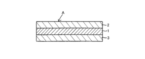
- the piezoelectric sensor A has a piezoelectric sheet 1 containing a porous synthetic resin sheet.
- the synthetic resin constituting the porous synthetic resin sheet is not particularly limited, for example, a polyethylene resin, a polyolefin resin such as a polypropylene resin, a fluorine resin such as polyvinylidene fluoride, a polylactic acid, a liquid crystal resin, Examples include a laminated sheet of a nonwoven fabric containing polytetrafluoroethylene, preferably including a polyolefin-based resin, and more preferably including a polypropylene-based resin.
- the synthetic resin is preferably excellent in insulating properties, and the synthetic resin may be a volume specific resistance value (hereinafter simply referred to as “volume specific resistance value”) after one minute of voltage application at an applied voltage of 500 V in accordance with JIS K6911. ) Is preferably 1.0 ⁇ 10 10 ⁇ ⁇ m or more.
- the volume resistivity value of the synthetic resin is preferably 1.0 ⁇ 10 12 ⁇ ⁇ m or more, and more preferably 1.0 ⁇ 10 14 ⁇ ⁇ m or more, because the piezoelectric sheet has more excellent piezoelectricity.
- polyethylene resin examples include an ethylene homopolymer, or a copolymer of ethylene containing an ethylene component in excess of 50% by mass and at least one ⁇ -olefin having 3 to 20 carbon atoms.
- ethylene homopolymer examples include low density polyethylene (LDPE) radically polymerized under high pressure, medium pressure low density polyethylene (HDPE) polymerized in the presence of a catalyst at medium and low pressure, and the like. By copolymerizing ethylene and ⁇ -olefin, linear low density polyethylene (LLDPE) can be obtained.
- LDPE low density polyethylene
- HDPE medium pressure low density polyethylene
- Examples of ⁇ -olefin include propylene, 1-butene, 1-pentene, 1-hexene, 4-methyl- Examples thereof include 1-pentene, 1-octene, 1-nonene, 1-decene, 1-tetradecene, 1-hexadecene, 1-octadecene, 1-eicosene and the like, and ⁇ -olefins having 4 to 10 carbon atoms are preferable.
- the content of ⁇ -olefin in the linear low density polyethylene is usually 1 to 15% by mass.
- the polypropylene resin is not particularly limited as long as it contains a propylene component in excess of 50% by mass.
- the number of carbons other than propylene homopolymer (homopolypropylene), propylene and at least one propylene is 20; Copolymers with the following olefins are exemplified.
- a polypropylene resin may be used independently or 2 or more types may be used together.
- the copolymer of propylene and at least one kind of olefin having 20 or less carbon atoms other than propylene may be either a block copolymer or a random copolymer.
- Examples of the ⁇ -olefin copolymerized with propylene include, for example, ethylene, 1-butene, 1-pentene, 4-methyl-1-pentene, 1-hexene, 1-octene, 1-nonene, 1-decene, Examples thereof include 1-tetradecene, 1-hexadecene, 1-octadecene, 1-eicosene and the like.
- the foaming ratio of the porous synthetic resin sheet is preferably 1.5 to 15 times, more preferably 2 to 10 times, particularly preferably 2 to 8 times, and most preferably 3 to 7 times. It is preferable that the foaming ratio of the porous synthetic resin sheet is 1.5 times or more because the stretchability in the surface direction of the piezoelectric sheet is excellent, and the stretchability and stretchability are improved. When the foaming ratio of the porous synthetic resin sheet is 15 times or less, the mechanical strength of the piezoelectric sensor is improved, or the bubble diameter is reduced and the piezoelectricity of the piezoelectric sheet is stabilized. It is preferable to improve.
- the expansion ratio of the porous synthetic resin sheet refers to a value obtained by dividing the density of the entire synthetic resin constituting the porous synthetic resin sheet by the density of the porous synthetic resin sheet.
- the porosity of the porous synthetic resin sheet is preferably 30% or more, more preferably 45% or more, and particularly preferably 60% or more.
- the porosity of the porous synthetic resin sheet is preferably 95% or less, more preferably 93% or less, and particularly preferably 90% or less. It is preferable that the porosity of the porous synthetic resin sheet is 30% or more because the piezoelectric sheet is excellent in stretchability in the surface direction, and the stretchability and stretchability are improved.
- the porosity of the porous synthetic resin sheet refers to a value obtained by multiplying 100 by the value obtained by dividing the total volume of pores in the porous synthetic resin sheet by the apparent volume of the porous synthetic resin sheet.
- the thickness of the porous synthetic resin sheet is preferably 10 to 300 ⁇ m, more preferably 30 to 200 ⁇ m. When the thickness of the porous synthetic resin sheet is 10 ⁇ m or more, the mechanical strength of the piezoelectric sheet is improved. It is preferable that the thickness of the porous synthetic resin sheet is 300 ⁇ m or less because the piezoelectricity of the piezoelectric sheet is stable.
- the expansion / contraction rate of the piezoelectric sheet 1 is preferably 0.5% or more, more preferably 1% or more, particularly preferably 1.5% or more, and most preferably 1.8% or more.
- the expansion / contraction rate of the piezoelectric sheet is preferably 30% or less, more preferably 20% or less, particularly preferably 10% or less, and most preferably 7% or less. It is preferable that the expansion / contraction rate of the piezoelectric sheet 1 is 0.5% or more because the expansion / contraction followability and the expansion / contraction detection property are improved.
- the expansion / contraction rate of the piezoelectric sheet 1 is 30% or less because the piezoelectric sheet maintains stable piezoelectricity over a long period of time, and expansion / contraction followability and expansion / contraction detection are improved.
- the electrical resistance value change rate at 5% elongation in the piezoelectric sheet 1 is preferably 10% or less, more preferably 8% or less, and particularly preferably 6% or less.
- the electrical resistance value change rate at 5% elongation in the piezoelectric sheet is a change rate between the initial electrical resistance value between two points and the electrical resistance value at 5% elongation, and the electrical resistance value at 5% elongation. The value obtained by dividing ( ⁇ ) by the initial electrical resistance value ( ⁇ ).
- the rate of change in electrical resistance value at 5% elongation of the piezoelectric sheet can be measured using, for example, a measuring device commercially available from Hioki Electric under the trade name “LCR meter”.
- the piezoelectric sheet 1 is constituted by charging a porous synthetic resin sheet.
- the method for charging the porous synthetic resin sheet is not particularly limited, and examples thereof include a method of applying direct current electrolysis to the porous synthetic resin sheet.
- the method for applying a direct current electric field to the porous synthetic resin sheet is not particularly limited.
- a flat plate electrode sandwiched between a pair of flat plate electrodes and brought into contact with a surface to be charged is used.
- a method of charging the porous synthetic resin sheet by connecting to a high-voltage DC power source and grounding the other flat plate electrode, applying a DC or pulsed high voltage to the porous synthetic resin sheet to inject charges into the synthetic resin,
- a grounded flat plate electrode is placed in close contact with the first surface of the porous synthetic resin sheet, and the second surface side of the porous synthetic resin sheet is placed at a predetermined interval to serve as a DC high-voltage power supply.
- An electrically connected acicular electrode or wire electrode is disposed, corona discharge is generated by electric field concentration near the tip of the acicular electrode or near the surface of the wire electrode, ionized air molecules, Wa
- the air ions generated by the polarity yer electrode is repelled and a method of charging a porous synthetic resin sheet and the like are.
- the absolute value of the DC processing voltage when a DC electric field is applied to the porous synthetic resin sheet is preferably 5 to 40 kV, more preferably 10 to 30 kV.
- the signal electrode layer 2 is laminated and integrated on one surface (first surface) of the piezoelectric sheet 1, and the ground electrode layer 3 is laminated and integrated on the other surface (second surface) of the piezoelectric sheet 1. It is configured. Then, by measuring the potential of the signal electrode using the ground electrode as a reference electrode, the potential generated in the piezoelectric sheet of the piezoelectric sensor can be measured.
- one surface (first surface) of the piezoelectric sheet 1 is a surface having the largest area of the piezoelectric sheet 1.
- the other surface (second surface) of the piezoelectric sheet 1 is a surface opposite to one surface (first surface) of the piezoelectric sheet 1.
- a signal electrode layer 2 containing conductive fine particles and a stretchable binder resin is laminated on one surface of the piezoelectric sheet 1. Since the signal electrode layer 2 is configured by dispersing conductive fine particles in a stretchable binder resin, the signal electrode layer 2 exhibits excellent stretchability, and the surface direction of the piezoelectric sensor on the surface to be measured is arranged. The movement of the object to be measured can be accurately detected by the piezoelectric sensor (extension / contraction followability), and the movement of the piezoelectric sensor on the surface of the object to be measured can be moved in the surface direction. It is possible to detect with high precision (extensibility detection).
- stacked on the one surface of the piezoelectric sheet 1 may be one, and the plurality may be patterned.
- a ground electrode layer 3 containing conductive fine particles and stretchable binder resin is laminated on the other surface of the piezoelectric sheet 1. Since the ground electrode layer 3 is configured by dispersing conductive fine particles in a stretchable binder resin, the ground electrode layer 3 exhibits excellent stretchability, and the surface direction of the piezoelectric sensor on the surface to be measured is arranged. The movement of the object to be measured can be accurately detected by the piezoelectric sensor (extension / contraction followability), and the movement of the piezoelectric sensor on the surface of the object to be measured can be moved in the surface direction. It is possible to detect with high precision (extensibility detection).
- stacked on the one surface of the piezoelectric sheet 1 may be one, and the plurality may be patterned.
- the conductive fine particles constituting the signal electrode layer 2 and the ground electrode layer 3 are not particularly limited as long as they can impart conductivity to the signal electrode layer 2 and the ground electrode layer 3.
- Metal fine particles such as copper fine particles, nickel fine particles, palladium fine particles, carbon-based conductive fine particles such as carbon black, graphite, carbon nanotube, carbon fiber, metal-coated carbon black, tungsten carbide, titanium nitride, zirconium nitride, titanium carbide, etc.
- Ceramic conductive fine particles and conductive potassium titanate whiskers examples thereof include ceramic conductive fine particles and conductive potassium titanate whiskers.
- Metal fine particles are preferable, and silver fine particles are more preferable.
- the conductive fine particles may be used alone or in combination of two or more.
- the conductive fine particles contained in the signal electrode layer 2 and the conductive fine particles contained in the ground electrode layer 3 may be the same or different.
- the average particle diameter of the conductive fine particles contained in the signal electrode layer 2 is preferably 0.01 to 50 ⁇ m, more preferably 0.1 to 30 ⁇ m, and particularly preferably 0.5 to 25 ⁇ m.
- the average particle size of the conductive fine particles contained in the ground electrode layer 3 is preferably 0.01 to 50 ⁇ m, more preferably 0.1 to 30 ⁇ m, and particularly preferably 0.5 to 25 ⁇ m.
- conductivity can be imparted to the signal electrode layer 2 and the ground electrode layer 3 while maintaining the stretchability of the signal electrode layer 2 and the ground electrode layer 3. .
- the average particle size of the conductive fine particles can be measured in the following manner.
- the signal electrode layer 2 and the ground electrode layer 3 are cut in the thickness direction, and an arbitrary portion of the cut surface is photographed with an electron microscope to obtain an enlarged photograph with a magnification of 1000 times.
- the diameters of arbitrary 100 conductive fine particles are measured.
- the diameter of the conductive fine particles refers to the diameter of the smallest perfect circle that can surround the conductive fine particles appearing in the enlarged photograph.
- the arithmetic average value of the diameters of the conductive fine particles is defined as the average particle diameter of the conductive fine particles.
- the content of the conductive fine particles contained in the signal electrode layer 2 is preferably 40 to 90 parts by weight, more preferably 60 to 85 parts by weight, and more preferably 60 to 80 parts by weight with respect to 100 parts by weight of the binder resin. Particularly preferred.
- the content of the conductive fine particles contained in the ground electrode layer 3 is preferably 40 to 90 parts by weight, more preferably 60 to 85 parts by weight, and more preferably 60 to 80 parts by weight with respect to 100 parts by weight of the binder resin. Particularly preferred.
- the binder resin constituting the signal electrode layer 2 and the ground electrode layer 3 follows the expansion and contraction in the surface direction of the piezoelectric sheet, and has a stretchable property that can expand and contract without causing damage such as cracks. In addition, it may be applied to the ground electrode layer 3.
- binder resin examples include modified silicone, acrylic modified polymer, styrene thermoplastic elastomer, polyolefin thermoplastic elastomer, polyvinyl chloride thermoplastic elastomer, polyurethane thermoplastic elastomer, polyester thermoplastic elastomer, and polyamide.
- thermoplastic elastomer such as 1,2-polybutadiene thermoplastic elastomer, polychloroprene (CR), EPDM, polyisoprene rubber (IR), polybutadiene rubber (BR), styrene-butadiene
- rubber materials such as heavy rubber (SBR), acrylonitrile-butadiene copolymer rubber (NBR), ethylene-propylene copolymer rubber, and butyl rubber.
- binder resin may be used independently or 2 or more types may be used together.
- a method for laminating and integrating the signal electrode layer 2 and the ground electrode layer 3 on the surface of the piezoelectric sheet 1 is not particularly limited.
- conductive fine particles and a binder resin are dispersed or dissolved in a solvent.
- a method of laminating and integrating the signal electrode layer 2 or the ground electrode layer 3 on the surface of the piezoelectric sheet 1 by applying the conductive paint to the surface of the piezoelectric sheet and then removing the solvent of the conductive paint.
- the curable resin After applying a conductive paint in which conductive fine particles are dispersed in a curable resin to the surface of the piezoelectric sheet, the curable resin is cured by heating or ionizing radiation to form a binder resin, and the signal electrode layer 2 or ground
- the electrode layer 3 may be laminated and integrated on the surface of the piezoelectric sheet 1.
- ionizing radiation include electron beams, ultraviolet rays, ⁇ rays, ⁇ rays, ⁇ rays, and the like.
- the stretch rate of the signal electrode layer 2 is preferably 0.5%, more preferably 3% or more, particularly preferably 5% or more, and most preferably 7% or more.
- the expansion / contraction rate of the signal electrode layer 2 is preferably 23% or less, more preferably 15% or less, particularly preferably 13% or less, and most preferably 11% or less. It is preferable that the expansion / contraction rate of the signal electrode layer 2 is 0.5% or more because the expansion / contraction followability and the expansion / contraction detection property are improved.
- the expansion / contraction rate of the signal electrode layer 2 is 23% or less, the accuracy of piezoelectricity of the piezoelectric sensor is improved, and the expansion / contraction followability and expansion / contraction detection property are improved.
- the expansion / contraction rate (%) of the signal electrode layer 2 is a value measured in the following manner. First, a plane square test piece having a side of 5 cm is cut out from the signal electrode layer 2, the test piece is stretched in a direction of an arbitrary edge with a force of 10 N, and the length (cm ). The expansion / contraction rate (%) of the signal electrode 2 is a value calculated based on the following formula.
- the expansion / contraction rate of the ground electrode layer 3 is preferably 0.5%, more preferably 3% or more, particularly preferably 5% or more, and most preferably 7% or more.
- the expansion / contraction rate of the ground electrode layer 3 is preferably 23% or less, more preferably 15% or less, particularly preferably 13% or less, and most preferably 11% or less.
- the expansion / contraction rate of the ground electrode layer 3 is 0.5% or more, the expansion / contraction followability and the expansion / contraction detection property are improved. It is preferable that the expansion / contraction rate of the ground electrode layer 3 is 23% or less because the accuracy of piezoelectricity of the piezoelectric sensor is improved and the expansion / contraction followability and expansion / contraction detection property are improved.
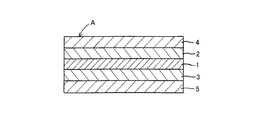
- the piezoelectric sensor A may be configured by laminating and integrating the surface of the piezoelectric sheet 1 toward the piezoelectric sheet 1 via a fixing agent as necessary.
- the stretchable synthetic resin sheets 4 and 5 are not particularly limited as long as they can expand and contract following the expansion and contraction in the surface direction of the piezoelectric sheet 1 without causing damage such as cracks.
- Examples of the synthetic resin constituting the stretchable synthetic resin sheets 4 and 5 include, for example, a styrene thermoplastic elastomer, a polyolefin thermoplastic elastomer, a polyvinyl chloride thermoplastic elastomer, a polyurethane thermoplastic elastomer, and a polyester thermoplastic.
- Elastomers polyamide thermoplastic elastomers, polyamide thermoplastic elastomers, thermoplastic elastomers, thermoplastic elastomers such as 1,2-polybutadiene thermoplastic elastomers, polychloroprene (CR), EPDM, polyisoprene rubber (IR), polybutadiene rubber (BR), Examples thereof include rubber materials such as styrene-butadiene copolymer rubber (SBR), acrylonitrile-butadiene copolymer rubber (NBR), ethylene-propylene copolymer rubber, and butyl rubber.
- binder resin may be used independently or 2 or more types may be used together.
- the stretch ratio of the stretchable synthetic resin sheets 4 and 5 is preferably 0.5% or more, more preferably 3% or more, particularly preferably 5% or more, and most preferably 7% or more.
- the stretch ratio of the stretchable synthetic resin sheets 4 and 5 is preferably 28% or less, more preferably 20% or less, particularly preferably 18% or less, and most preferably 16% or less. It is preferable that the stretchability of the stretchable synthetic resin sheets 4 and 5 is 0.5% or more because stretchability followability and stretchability detectability are improved. It is preferable that the stretchability of the stretchable synthetic resin sheets 4 and 5 is 28% or less because the piezoelectricity of the piezoelectric sensor is improved.
- the expansion / contraction rate (%) of the stretchable synthetic resin sheets 4 and 5 is a value measured in the following manner. First, a test piece having a flat square shape with a side of 5 cm is cut out from the stretchable synthetic resin sheets 4 and 5, and this test piece is stretched in a direction of an arbitrary edge with a force of 10 N. Measure length (cm).
- the stretch ratio (%) of the stretchable synthetic resin sheets 4 and 5 is a value calculated based on the following formula.
- the method for supporting the signal electrode layer 2 or the ground electrode layer 3 on the surfaces of the stretchable synthetic resin sheets 4 and 5 is not particularly limited.
- conductive fine particles and a binder resin are dispersed in a solvent or After applying the dissolved conductive paint to the surface of the stretchable synthetic resin sheet, the signal electrode layer 2 or the ground electrode layer 3 is removed from the stretchable synthetic resin sheets 4 and 5 by removing the solvent of the conductive paint.
- the curable resin is heated or ionized.
- a method in which the signal electrode layer 2 or the ground electrode layer 3 is laminated and integrated on the surfaces of the stretchable synthetic resin sheets 4 and 5 and the like.
- the piezoelectric sheet and the stretchable synthetic resin sheet can be subjected to a known surface treatment for the purpose of improving the adhesion of the conductive paint.
- a known surface treatment for the purpose of improving the adhesion of the conductive paint.
- the surface treatment method include corona treatment, primer treatment, and sandblast treatment.
- the method of laminating and integrating the stretchable synthetic resin sheets 4 and 5 carrying the signal electrode layer 2 or the ground electrode layer 3 on the surface of the piezoelectric sheet 1 is not particularly limited.
- the signal electrode layer 2 when the ground electrode layer 3 has adhesiveness or adhesiveness, the signal electrode layer 2 or the ground electrode layer is formed on the surface of the piezoelectric sheet 1 by the adhesiveness of the signal electrode layer 2 or the ground electrode layer 3. 3 (see FIG. 2), (2) the stretchable synthetic resin sheets 4 and 5 carrying the signal electrode layer 2 or the ground electrode layer 3 And a method of stacking and integrating on the surface of the piezoelectric sheet 1 via the fixing agents 6 and 7 having elasticity (see FIG. 3).
- the fixing agents 6 and 7 are composed of a reaction system, a solvent system, an aqueous system, a hot melt system adhesive or a pressure sensitive adhesive. From the viewpoint of maintaining the sensitivity of the piezoelectric sheet 1, a fixing agent having a low dielectric constant is used. preferable.
- the fixing agents 6 and 7 include an adhesive such as an acrylic adhesive and a double-sided adhesive tape.
- the stretch ratio of the fixative is 0.5. % Or more, more preferably 3% or more, particularly preferably 5% or more, and most preferably 7% or more.
- the expansion / contraction rate of the fixing agent is preferably 70% or less, more preferably 65% or less, and particularly preferably 60% or less. When the expansion / contraction rate of the fixing agent is 0.5% or more, it is preferable because expansion / contraction followability and expansion / contraction detection are improved.
- the fixing agent has elasticity, it is possible to effectively prevent peeling between the elastic synthetic resin sheets 4 and 5 and the piezoelectric sheet 1. It is preferable that the expansion / contraction ratio of the fixing agent is 70% or less because the piezoelectric sensor maintains excellent piezoelectricity over time.
- the expansion / contraction rate (%) of a fixing agent means the value measured in the following way. First, a plane square-shaped test piece having a side of 5 cm is cut out from the fixing agent, and this test piece is extended in a direction of an arbitrary edge with a force of 10 N, and the length (cm) of the test piece in the extending direction at the time of extension is set. taking measurement.
- the expansion / contraction rate (%) of the fixative refers to a value calculated based on the following formula.
- the piezoelectric sensor A configured as described above has the piezoelectric sheet 1, the signal electrode layer 2, the ground electrode layer 3, the stretchable synthetic resin sheets 4, 5, and the fixing agents 6, 7 constituting the piezoelectric sensor A.
- the stretchable synthetic resin sheets 4 and 5 and the fixing agents 6 and 7 are stretchable in the surface direction of the piezoelectric sheet 1. Therefore, the piezoelectric sensor A attached in close contact with the measurement object smoothly expands and contracts following the movement in the surface direction of the surface on which the piezoelectric sensor is arranged in the measurement object, and is applied to the surface of the measurement object. It is possible to maintain a good close contact state and accurately detect the movement of the measurement object.
- the piezoelectric sensor A can smoothly follow the movement in the surface direction of the surface (the surface on which the piezoelectric sensor is disposed) on the object (measurement object) from which the motion is detected. Therefore, even the skin of a human body that moves finely can be followed smoothly.
- the piezoelectric sensor A can be suitably used for applications that are attached to the human skin or attached to the human body, so-called wearable applications, and can accurately detect biological signals such as pulse waves and respiratory signals. it can.
- transportation apparatuses such as a human body, a concrete structure, a bridge, a vehicle, etc. are mentioned, for example.
- the piezoelectric sensor A expands and contracts smoothly following the movement in the surface direction of the surface where the piezoelectric sensor is disposed in the object to be measured.
- the thickness of the piezoelectric sheet 1 changes in the thickness direction, Electric charges are developed with this change in thickness. By detecting this electric charge, it is possible to accurately detect the movement in the surface direction of the mounting surface of the piezoelectric sensor in the measurement object.
- the wall surface of a concrete structure such as a building deteriorates over time due to exposure to sunlight or wind and rain, and cracks such as cracks occur. Movement occurs. Therefore, if the piezoelectric sensor A is adhered to the wall surface of the concrete structure in close contact, the piezoelectric sensor A accurately detects the movement of the wall surface due to the crack, and damage such as cracks generated in the concrete structure is promptly detected. It can be recognized and the subsequent response can be performed smoothly.
- the expansion / contraction rate of the entire piezoelectric sensor A is preferably 0.5% or more, more preferably 0.7% or more, more preferably 0.8% or more, and particularly preferably 0.9% or more.
- the expansion / contraction rate of the entire piezoelectric sensor A is preferably 15% or less, more preferably 13% or less, particularly preferably 11% or less, and most preferably 4% or less.
- the expansion / contraction rate of the entire piezoelectric sensor A is 0.5% or more, the expansion / contraction followability and the expansion / contraction detection property are preferably improved.
- the expansion / contraction rate of the entire piezoelectric sensor A is preferably 15% or less because the piezoelectric sensor maintains excellent piezoelectricity over time.
- the expansion rate (%) of the entire piezoelectric sensor A is a value measured in the following manner. First, a plane square test piece having a side of 5 cm is cut out from the piezoelectric sensor A, the test piece is extended in a direction of an arbitrary edge with a force of 10 N, and the length of the test piece in the extension direction at the time of extension (cm) Measure.
- the expansion / contraction rate (%) of the piezoelectric sensor A is a value calculated based on the following equation.
- Examples 1 to 5 100 parts by mass of a propylene-ethylene random copolymer (trade name “Novatech EG8B” manufactured by Nippon Polypro Co., Ltd., ethylene unit content: 5% by mass), 3.3 parts by mass of trimethylolpropane trimethacrylate, azodicarbonamide and phenolic 2 parts by mass of an antioxidant was supplied to an extruder, melted and kneaded and extruded from a T-die into a sheet to produce a foamable resin sheet having a thickness of 180 ⁇ m. The foamable resin sheet was cut into a planar square shape with a side of 30 cm. The amount of azodicarbonamide shown in Table 1 was supplied to the extruder.
- the propylene-ethylene random copolymer constituting the expandable resin sheet was cross-linked by irradiating both surfaces of the obtained expandable resin sheet with an electron beam under conditions of an acceleration voltage of 300 kV and an intensity of 25 kGy.
- the foamable resin sheet was heated to 250 ° C. to foam the foamable resin sheet to obtain a foamed sheet.
- the obtained foamed sheet was uniaxially stretched after its surface temperature was heated to 140 ° C. Table 1 shows the expansion ratio, thickness, and porosity of the foam sheet.
- the corona discharge is generated under the conditions of a voltage of ⁇ 20 kV, a discharge distance of 10 mm, and a voltage application time of 1 minute due to electric field concentration near the surface of the needle-like electrode, and the air molecules are ionized to form a needle-like shape.
- Air ions generated due to the polarity of the electrodes were repelled and a direct current electric field was applied to the foamed sheet to inject a charge to charge the foamed sheet as a whole. Thereafter, the foam sheet into which electric charges were injected was held for 3 hours in a state of being wrapped with a grounded aluminum foil to obtain a piezoelectric sheet.
- the piezoelectric constant d33 of the piezoelectric sheet is shown in Table 1.
- a stretchable synthetic resin sheet As a stretchable synthetic resin sheet, a stretchable polyurethane-based thermoplastic elastomer sheet having a thickness of 50 ⁇ m (trade name “Tough Grace” manufactured by Takeda Sangyo Co., Ltd.) and a stretchable polyurethane-based thermoplastic elastomer sheet having a thickness of 25 ⁇ m (Takeda) Sangyo Co., Ltd. (trade name “Tough Grace”) was prepared two by two. A polyurethane-based thermoplastic elastomer sheet having the thickness shown in Table 1 was selected.
- a conductive paint (trade name “SX-ECA48” manufactured by Cemedine Co., Ltd.) containing silver fine particles (average particle diameter: 2 ⁇ m) and an acrylic-modified polymer as a curable resin was prepared. After applying a conductive paint on one surface of each of the two polyurethane-based thermoplastic elastomer sheets, the conductive paint is heated at 100 ° C. for 3 hours to cure the curable resin to form a binder resin. An electrode layer in which silver fine particles were uniformly dispersed therein was laminated and integrated on one surface of a polyurethane-based thermoplastic elastomer sheet. The thickness of the electrode layer is shown in Table 1.
- the binder resin had elasticity.
- the electrode layer contained 65 parts by mass of silver fine particles with respect to 100 parts by mass of the binder resin.
- a double-sided adhesive tape (trade name “WT # 5402”, thickness 25 ⁇ m, manufactured by Sekisui Chemical Co., Ltd.) was prepared as a fixing agent.
- a double-sided adhesive tape was stuck as a fixing agent on both sides of the piezoelectric sheet.
- a polyurethane-based thermoplastic elastomer sheet was laminated and integrated with a fixing agent on both sides of the piezoelectric sheet so that the electrode layer was on the piezoelectric sheet side to obtain a piezoelectric sheet.
- the fixative had elasticity.
- the electrode layer carried on one surface of the polyurethane-based thermoplastic elastomer sheet laminated and integrated on one surface of the piezoelectric sheet 1 was used as a signal electrode layer.
- the electrode layer carried on one surface of the polyurethane-based thermoplastic elastomer sheet laminated and integrated on the other surface of the piezoelectric sheet 1 was used as a ground electrode layer.
- the polyurethane-based thermoplastic elastomer sheet, the signal electrode layer, and the ground electrode layer were in the form of a planar square having a side of 6 cm and the same size as the piezoelectric sheet. An electric wire was connected to each of the signal electrode layer and the ground electrode layer.
- Example 1 A piezoelectric sensor was obtained in the same manner as in Example 1 except that an electrode layer made of an aluminum foil having a thickness of 10 ⁇ m was laminated and integrated on one surface of two polyurethane thermoplastic elastomer sheets via a double-sided adhesive tape. It was. In addition, the electrode layer which consists of aluminum foil did not have a stretching property.
- Example 2 A piezoelectric sensor was obtained in the same manner as in Example 1 except that an electrode layer made of aluminum was formed on one surface of two polyurethane-based thermoplastic elastomer sheets by sputtering. In addition, the electrode layer which consists of aluminum did not have a stretching property.
- Example 3 A piezoelectric sensor was obtained in the same manner as in Example 1 except that a polyethylene terephthalate sheet having a thickness of 50 ⁇ m was used instead of the polyurethane-based thermoplastic elastomer sheet. The polyethylene terephthalate sheet did not have stretchability.
- the expansion / contraction ratio of the obtained piezoelectric sensor was measured, and the result is shown in Table 1.
- the expansion ratios of the piezoelectric sheet, the fixing agent, the signal electrode layer, the ground electrode layer, and the stretchable synthetic resin sheet constituting the piezoelectric sensor were measured as described above, and the results are shown in Table 1.
- the electrode layer made of aluminum could not be isolated, and the expansion / contraction ratios of the signal electrode layer and the ground electrode layer could not be measured.
- a planar square rubber sheet having elasticity and having a size slightly larger than that of the piezoelectric sensor was prepared.
- a piezoelectric sensor was attached to one surface of a rubber sheet in a close contact state with a double-sided adhesive tape having elasticity, to prepare a test specimen. Adjustment was made so that the edge of the piezoelectric sensor and the edge of the rubber sheet were parallel to each other.
- a pressing force was applied under the conditions of a load F of 1 N, a dynamic load of ⁇ 0.5 N, a frequency of 30 Hz, and a pressing area of 1 cm 2 , and the voltage generated at that time was measured.
- the voltage was read from peak to peak.
- the voltage was read using an oscilloscope (Texio Technology) through an amplifier (MSI).
- the voltage of the piezoelectric sheet immediately after the piezoelectric sensor was stuck on the rubber sheet was measured and used as the initial voltage.
- the voltage of the piezoelectric sheet was measured in the same manner as described above to obtain the extended voltage.
- the aluminum layer is disconnected when stretched, and in the piezoelectric sensors of Comparative Examples 1 and 3, the signal electrode layer and the ground electrode layer are peeled off from the surface of the piezoelectric sheet when stretched. The voltage could not be measured.
- the piezoelectric sensor of the present invention has elasticity in the surface direction, even when the surface on which the piezoelectric sensor is disposed in the object to be measured expands and contracts in the surface direction, the object to be measured can be smoothly expanded and contracted. , And maintaining excellent adhesion to the measured object, and the movement of the measured object can be accurately measured. Furthermore, the piezoelectric sensor of the present invention can also detect the movement in the surface direction of the mounting surface of the piezoelectric sensor in the measurement object.
- the piezoelectric sensor of the present invention can be suitably used for wearable applications.
- the piezoelectric sensor of the present invention can be used for measuring the movement of a measurement object such as a transportation device such as a vehicle, a human body, a concrete structure, or a bridge.
Landscapes
- Physics & Mathematics (AREA)
- General Physics & Mathematics (AREA)
- Spectroscopy & Molecular Physics (AREA)
- Engineering & Computer Science (AREA)
- Manufacturing & Machinery (AREA)
- Measurement Of Length, Angles, Or The Like Using Electric Or Magnetic Means (AREA)
- Investigating Or Analyzing Materials By The Use Of Ultrasonic Waves (AREA)
- Piezo-Electric Transducers For Audible Bands (AREA)
- Laminated Bodies (AREA)
Abstract
Description
伸縮率(%)
=100×〔伸長時における伸長方向の試験片の長さ(cm)-5〕/5
伸縮率(%)
=100×〔伸長時における伸長方向の試験片の長さ(cm)-5〕/5
伸縮率(%)
=100×〔伸長時における伸長方向の試験片の長さ(cm)-5〕/5
伸縮率(%)
=100×〔伸長時における伸長方向の試験片の長さ(cm)-5〕/5
伸縮率(%)
=100×〔伸長時における伸長方向の試験片の長さ(cm)-5〕/5
伸縮率(%)
=100×〔伸長時における伸長方向の試験片の長さ(cm)-5〕/5
プロピレン-エチレンランダム共重合体(日本ポリプロ社製 商品名「ノバテックEG8B」、エチレン単位の含有量:5質量%)100質量部、トリメチロールプロパントリメタクリレート3.3質量部、アゾジカルボンアミド及びフェノール系酸化防止剤2質量部を押出機に供給して溶融混練してTダイからシート状に押出し、厚みが180μmである発泡性樹脂シートを製造した。発泡性樹脂シートを一辺が30cmの平面正方形状に切り出した。アゾジカルボンアミドは表1に示した量を押出機に供給した。
2枚のポリウレタン系熱可塑性エラストマーシートの一面のそれぞれに厚みが10μmのアルミニウム箔からなる電極層を両面粘着テープを介して積層一体化したこと以外は実施例1と同様の要領で圧電センサを得た。なお、アルミニウム箔からなる電極層は伸縮性を有していなかった。
2枚のポリウレタン系熱可塑性エラストマーシートの一面のそれぞれにスパッタリングによってアルミニウムからなる電極層を形成したこと以外は実施例1と同様の要領で圧電センサを得た。なお、アルミニウムからなる電極層は伸縮性を有していなかった。
ポリウレタン系熱可塑性エラストマーシートの代わりに、厚みが50μmのポリエチレンテレフタレートシートを用いたこと以外は実施例1と同様の要領で圧電センサを得た。なお、ポリエチレンテレフタレートシートは伸縮性を有していなかった。
伸縮性を有し且つ圧電センサよりも一回り大きな大きさを有する平面正方形状のゴムシートを用意した。圧電センサをゴムシートの一面に伸縮性を有する両面粘着テープを介して密着状態に貼着して試験体を作製した。圧電センサの端縁とゴムシートの端縁とが互いに平行になるように調節した。
伸長率(%)=100×伸長後の伸長方向のゴムシートの寸法
/伸長前の伸長方向のゴムシートの寸法
伸縮追従性の測定時と同様の要領で試験体を作製した。ゴムシートをテンシロン(オリエンテック社製)を用いて任意の端縁に沿って伸長率1%又は5%だけ伸長させ、伸長時に発生する電圧を計測した。電圧は、伸び縮みのpeak to peakを測定した。

本出願は、2016年9月6日に出願された日本国特許出願第2016-174038号に基づく優先権を主張し、この出願の開示はこれらの全体を参照することにより本明細書に組み込まれる。
2 シグナル電極層
3 グランド電極層
4、5 伸縮性合成樹脂シート
6、7 固定剤
A 圧電センサ
Claims (3)
- 多孔質合成樹脂シートを含有する圧電シートと、上記圧電シートの一面に積層され且つ導電性微粒子及び伸縮性を有する結着樹脂を含むシグナル電極層と、上記圧電シートの他面に積層され且つ導電性微粒子及び伸縮性を有する結着樹脂を含むグランド電極層とを有することを特徴とする圧電センサ。
- シグナル電極層及び/又はグランド電極層は、伸縮性合成樹脂シートに担持されていることを特徴とする請求項1に記載の圧電センサ。
- 伸縮性合成樹脂シートは、熱可塑性エラストマーシート又はゴムシートを含有していることを特徴とする請求項1又は請求項2に記載の圧電センサ。
Priority Applications (5)
| Application Number | Priority Date | Filing Date | Title |
|---|---|---|---|
| JP2017549830A JP7271084B2 (ja) | 2016-09-06 | 2017-09-06 | 圧電センサ |
| EP17848816.9A EP3511673B1 (en) | 2016-09-06 | 2017-09-06 | Piezoelectric sensor |
| US16/330,424 US11264556B2 (en) | 2016-09-06 | 2017-09-06 | Piezoelectric sensor |
| KR1020197007295A KR102638861B1 (ko) | 2016-09-06 | 2017-09-06 | 압전 센서 |
| CN201780053765.3A CN109661558A (zh) | 2016-09-06 | 2017-09-06 | 压电传感器 |
Applications Claiming Priority (2)
| Application Number | Priority Date | Filing Date | Title |
|---|---|---|---|
| JP2016174038 | 2016-09-06 | ||
| JP2016-174038 | 2016-09-06 |
Publications (1)
| Publication Number | Publication Date |
|---|---|
| WO2018047878A1 true WO2018047878A1 (ja) | 2018-03-15 |
Family
ID=61562501
Family Applications (1)
| Application Number | Title | Priority Date | Filing Date |
|---|---|---|---|
| PCT/JP2017/032173 Ceased WO2018047878A1 (ja) | 2016-09-06 | 2017-09-06 | 圧電センサ |
Country Status (6)
| Country | Link |
|---|---|
| US (1) | US11264556B2 (ja) |
| EP (1) | EP3511673B1 (ja) |
| JP (1) | JP7271084B2 (ja) |
| KR (1) | KR102638861B1 (ja) |
| CN (1) | CN109661558A (ja) |
| WO (1) | WO2018047878A1 (ja) |
Cited By (1)
| Publication number | Priority date | Publication date | Assignee | Title |
|---|---|---|---|---|
| CN108577853A (zh) * | 2018-04-27 | 2018-09-28 | 福州大学 | 一种用于检测人体关节运动的可穿戴式应变传感器及其制备方法 |
Families Citing this family (6)
| Publication number | Priority date | Publication date | Assignee | Title |
|---|---|---|---|---|
| CN110081811B (zh) * | 2019-05-27 | 2021-04-27 | 合肥京东方光电科技有限公司 | 一种传感器结构及其制备方法,应变监测方法及装置 |
| WO2022025232A1 (ja) * | 2020-07-30 | 2022-02-03 | 株式会社村田製作所 | 変形検出センサ |
| TWI782624B (zh) * | 2021-07-14 | 2022-11-01 | 國立臺灣科技大學 | 曲面傳感器及其製造方法 |
| KR102699450B1 (ko) * | 2021-11-05 | 2024-09-02 | 한양대학교 산학협력단 | 다공성 유전부를 포함하는 유연성 구조체, 이의 제조방법 및 이를 포함하는 마찰전기 생성장치 |
| US20230160762A1 (en) * | 2021-11-25 | 2023-05-25 | National Taiwan University Of Science And Technology | Pressure Sensing Element with Porous Structure Based Flexible Base |
| CN119309712A (zh) * | 2024-11-05 | 2025-01-14 | 济南大学 | 一种基于压电薄膜的车辆动态轴载监测传感器制作方法及传感器 |
Citations (4)
| Publication number | Priority date | Publication date | Assignee | Title |
|---|---|---|---|---|
| US20080175450A1 (en) * | 1999-08-09 | 2008-07-24 | Cross Match Technologies, Inc. | Biometric piezo scanner |
| JP2009192231A (ja) * | 2008-02-12 | 2009-08-27 | Panasonic Corp | 圧電素子 |
| JP2012225727A (ja) * | 2011-04-19 | 2012-11-15 | Tokai Rubber Ind Ltd | 静電容量型センサ装置 |
| JP2015184122A (ja) * | 2014-03-24 | 2015-10-22 | 積水化学工業株式会社 | 圧電センサ |
Family Cites Families (11)
| Publication number | Priority date | Publication date | Assignee | Title |
|---|---|---|---|---|
| JPS5927584A (ja) * | 1982-08-05 | 1984-02-14 | Agency Of Ind Science & Technol | 高分子複合多孔質圧電体およびその製造方法 |
| US4624796A (en) * | 1985-06-07 | 1986-11-25 | Celanese Corporation | Piezoelectric filler and flexible piezoelectric composites |
| JP2005347364A (ja) * | 2004-06-01 | 2005-12-15 | National Institute Of Advanced Industrial & Technology | 伸縮可能な圧電素子 |
| WO2008021191A2 (en) * | 2006-08-09 | 2008-02-21 | The Johns Hopkins University | Piezoelectric compositions |
| JP5701508B2 (ja) | 2009-03-04 | 2015-04-15 | 日東電工株式会社 | 導電性を有する樹脂発泡体 |
| JP5562895B2 (ja) * | 2011-04-19 | 2014-07-30 | 中国電力株式会社 | 日射量推定装置、日射量推定方法及びプログラム |
| JP2014199226A (ja) | 2013-03-29 | 2014-10-23 | 積水化学工業株式会社 | 生体情報取得衣類 |
| CN103531706B (zh) | 2013-10-22 | 2016-05-25 | 深圳市豪恩声学股份有限公司 | 压电驻极体材料及其制备方法 |
| JP2016033580A (ja) | 2014-07-31 | 2016-03-10 | ヤマハ株式会社 | 電子打楽器用パッド |
| CN106289595A (zh) * | 2015-05-26 | 2017-01-04 | 鸿富锦精密工业(深圳)有限公司 | 能够侦测剪切力的力传感器 |
| CN107924986B (zh) * | 2015-07-16 | 2021-02-23 | 住友理工株式会社 | 压电传感器 |
-
2017
- 2017-09-06 KR KR1020197007295A patent/KR102638861B1/ko active Active
- 2017-09-06 CN CN201780053765.3A patent/CN109661558A/zh active Pending
- 2017-09-06 WO PCT/JP2017/032173 patent/WO2018047878A1/ja not_active Ceased
- 2017-09-06 US US16/330,424 patent/US11264556B2/en active Active
- 2017-09-06 EP EP17848816.9A patent/EP3511673B1/en active Active
- 2017-09-06 JP JP2017549830A patent/JP7271084B2/ja active Active
Patent Citations (4)
| Publication number | Priority date | Publication date | Assignee | Title |
|---|---|---|---|---|
| US20080175450A1 (en) * | 1999-08-09 | 2008-07-24 | Cross Match Technologies, Inc. | Biometric piezo scanner |
| JP2009192231A (ja) * | 2008-02-12 | 2009-08-27 | Panasonic Corp | 圧電素子 |
| JP2012225727A (ja) * | 2011-04-19 | 2012-11-15 | Tokai Rubber Ind Ltd | 静電容量型センサ装置 |
| JP2015184122A (ja) * | 2014-03-24 | 2015-10-22 | 積水化学工業株式会社 | 圧電センサ |
Non-Patent Citations (1)
| Title |
|---|
| See also references of EP3511673A4 * |
Cited By (1)
| Publication number | Priority date | Publication date | Assignee | Title |
|---|---|---|---|---|
| CN108577853A (zh) * | 2018-04-27 | 2018-09-28 | 福州大学 | 一种用于检测人体关节运动的可穿戴式应变传感器及其制备方法 |
Also Published As
| Publication number | Publication date |
|---|---|
| JP7271084B2 (ja) | 2023-05-11 |
| EP3511673B1 (en) | 2025-10-22 |
| KR102638861B1 (ko) | 2024-02-22 |
| CN109661558A (zh) | 2019-04-19 |
| US11264556B2 (en) | 2022-03-01 |
| KR20190044636A (ko) | 2019-04-30 |
| US20210280770A1 (en) | 2021-09-09 |
| JPWO2018047878A1 (ja) | 2019-06-24 |
| EP3511673A4 (en) | 2020-06-17 |
| EP3511673A1 (en) | 2019-07-17 |
Similar Documents
| Publication | Publication Date | Title |
|---|---|---|
| JP7271084B2 (ja) | 圧電センサ | |
| JP7411022B2 (ja) | エレクトレットシート | |
| TWI791491B (zh) | 壓電感測器 | |
| JP6959013B2 (ja) | エレクトレットシート | |
| KR102637368B1 (ko) | 일렉트릿 시트 | |
| JP7036538B2 (ja) | エレクトレットシート | |
| JP7198189B2 (ja) | 圧電シート及びその製造方法並びに圧電センサ | |
| JP7271641B2 (ja) | エレクトレットシート | |
| KR102588134B1 (ko) | 일렉트릿 시트 | |
| JP6798898B2 (ja) | エレクトレットシート | |
| JP2017179126A (ja) | エレクトレットシート及び圧電センサ | |
| JP2022183079A (ja) | エレクトレットシート、圧電センサ、圧力検出システム及びエレクトレットシートの製造方法 | |
| JP2013216816A (ja) | エレクトレットシート |
Legal Events
| Date | Code | Title | Description |
|---|---|---|---|
| WWE | Wipo information: entry into national phase |
Ref document number: 2017549830 Country of ref document: JP |
|
| 121 | Ep: the epo has been informed by wipo that ep was designated in this application |
Ref document number: 17848816 Country of ref document: EP Kind code of ref document: A1 |
|
| NENP | Non-entry into the national phase |
Ref country code: DE |
|
| ENP | Entry into the national phase |
Ref document number: 20197007295 Country of ref document: KR Kind code of ref document: A |
|
| ENP | Entry into the national phase |
Ref document number: 2017848816 Country of ref document: EP Effective date: 20190408 |
|
| WWG | Wipo information: grant in national office |
Ref document number: 2017848816 Country of ref document: EP |