WO2018047954A1 - 俯瞰画像システム、俯瞰画像表示方法及びプログラム - Google Patents
俯瞰画像システム、俯瞰画像表示方法及びプログラム Download PDFInfo
- Publication number
- WO2018047954A1 WO2018047954A1 PCT/JP2017/032534 JP2017032534W WO2018047954A1 WO 2018047954 A1 WO2018047954 A1 WO 2018047954A1 JP 2017032534 W JP2017032534 W JP 2017032534W WO 2018047954 A1 WO2018047954 A1 WO 2018047954A1
- Authority
- WO
- WIPO (PCT)
- Prior art keywords
- image
- traveling body
- camera
- bird
- eye view
- Prior art date
- Legal status (The legal status is an assumption and is not a legal conclusion. Google has not performed a legal analysis and makes no representation as to the accuracy of the status listed.)
- Ceased
Links
Images


Classifications
-
- B—PERFORMING OPERATIONS; TRANSPORTING
- B66—HOISTING; LIFTING; HAULING
- B66C—CRANES; LOAD-ENGAGING ELEMENTS OR DEVICES FOR CRANES, CAPSTANS, WINCHES, OR TACKLES
- B66C13/00—Other constructional features or details
- B66C13/18—Control systems or devices
- B66C13/46—Position indicators for suspended loads or for crane elements
-
- B—PERFORMING OPERATIONS; TRANSPORTING
- B60—VEHICLES IN GENERAL
- B60R—VEHICLES, VEHICLE FITTINGS, OR VEHICLE PARTS, NOT OTHERWISE PROVIDED FOR
- B60R1/00—Optical viewing arrangements; Real-time viewing arrangements for drivers or passengers using optical image capturing systems, e.g. cameras or video systems specially adapted for use in or on vehicles
- B60R1/20—Real-time viewing arrangements for drivers or passengers using optical image capturing systems, e.g. cameras or video systems specially adapted for use in or on vehicles
- B60R1/22—Real-time viewing arrangements for drivers or passengers using optical image capturing systems, e.g. cameras or video systems specially adapted for use in or on vehicles for viewing an area outside the vehicle, e.g. the exterior of the vehicle
- B60R1/23—Real-time viewing arrangements for drivers or passengers using optical image capturing systems, e.g. cameras or video systems specially adapted for use in or on vehicles for viewing an area outside the vehicle, e.g. the exterior of the vehicle with a predetermined field of view
- B60R1/27—Real-time viewing arrangements for drivers or passengers using optical image capturing systems, e.g. cameras or video systems specially adapted for use in or on vehicles for viewing an area outside the vehicle, e.g. the exterior of the vehicle with a predetermined field of view providing all-round vision, e.g. using omnidirectional cameras
-
- B—PERFORMING OPERATIONS; TRANSPORTING
- B60—VEHICLES IN GENERAL
- B60R—VEHICLES, VEHICLE FITTINGS, OR VEHICLE PARTS, NOT OTHERWISE PROVIDED FOR
- B60R11/00—Arrangements for holding or mounting articles, not otherwise provided for
- B60R11/02—Arrangements for holding or mounting articles, not otherwise provided for for radio sets, television sets, telephones, or the like; Arrangement of controls thereof
-
- B—PERFORMING OPERATIONS; TRANSPORTING
- B60—VEHICLES IN GENERAL
- B60R—VEHICLES, VEHICLE FITTINGS, OR VEHICLE PARTS, NOT OTHERWISE PROVIDED FOR
- B60R11/00—Arrangements for holding or mounting articles, not otherwise provided for
- B60R11/04—Mounting of cameras operative during drive; Arrangement of controls thereof relative to the vehicle
-
- B—PERFORMING OPERATIONS; TRANSPORTING
- B66—HOISTING; LIFTING; HAULING
- B66C—CRANES; LOAD-ENGAGING ELEMENTS OR DEVICES FOR CRANES, CAPSTANS, WINCHES, OR TACKLES
- B66C13/00—Other constructional features or details
-
- B—PERFORMING OPERATIONS; TRANSPORTING
- B66—HOISTING; LIFTING; HAULING
- B66C—CRANES; LOAD-ENGAGING ELEMENTS OR DEVICES FOR CRANES, CAPSTANS, WINCHES, OR TACKLES
- B66C23/00—Cranes comprising essentially a beam, boom, or triangular structure acting as a cantilever and mounted for translatory of swinging movements in vertical or horizontal planes or a combination of such movements, e.g. jib-cranes, derricks, tower cranes
- B66C23/88—Safety gear
- B66C23/90—Devices for indicating or limiting lifting moment
-
- B—PERFORMING OPERATIONS; TRANSPORTING
- B66—HOISTING; LIFTING; HAULING
- B66C—CRANES; LOAD-ENGAGING ELEMENTS OR DEVICES FOR CRANES, CAPSTANS, WINCHES, OR TACKLES
- B66C23/00—Cranes comprising essentially a beam, boom, or triangular structure acting as a cantilever and mounted for translatory of swinging movements in vertical or horizontal planes or a combination of such movements, e.g. jib-cranes, derricks, tower cranes
- B66C23/88—Safety gear
- B66C23/90—Devices for indicating or limiting lifting moment
- B66C23/905—Devices for indicating or limiting lifting moment electrical
-
- E—FIXED CONSTRUCTIONS
- E02—HYDRAULIC ENGINEERING; FOUNDATIONS; SOIL SHIFTING
- E02F—DREDGING; SOIL-SHIFTING
- E02F9/00—Component parts of dredgers or soil-shifting machines, not restricted to one of the kinds covered by groups E02F3/00 - E02F7/00
- E02F9/26—Indicating devices
-
- G—PHYSICS
- G06—COMPUTING OR CALCULATING; COUNTING
- G06T—IMAGE DATA PROCESSING OR GENERATION, IN GENERAL
- G06T1/00—General purpose image data processing
-
- H—ELECTRICITY
- H04—ELECTRIC COMMUNICATION TECHNIQUE
- H04N—PICTORIAL COMMUNICATION, e.g. TELEVISION
- H04N7/00—Television systems
- H04N7/18—Closed-circuit television [CCTV] systems, i.e. systems in which the video signal is not broadcast
-
- H—ELECTRICITY
- H04—ELECTRIC COMMUNICATION TECHNIQUE
- H04N—PICTORIAL COMMUNICATION, e.g. TELEVISION
- H04N7/00—Television systems
- H04N7/18—Closed-circuit television [CCTV] systems, i.e. systems in which the video signal is not broadcast
- H04N7/181—Closed-circuit television [CCTV] systems, i.e. systems in which the video signal is not broadcast for receiving images from a plurality of remote sources
-
- B—PERFORMING OPERATIONS; TRANSPORTING
- B60—VEHICLES IN GENERAL
- B60R—VEHICLES, VEHICLE FITTINGS, OR VEHICLE PARTS, NOT OTHERWISE PROVIDED FOR
- B60R2300/00—Details of viewing arrangements using cameras and displays, specially adapted for use in a vehicle
- B60R2300/10—Details of viewing arrangements using cameras and displays, specially adapted for use in a vehicle characterised by the type of camera system used
- B60R2300/105—Details of viewing arrangements using cameras and displays, specially adapted for use in a vehicle characterised by the type of camera system used using multiple cameras
-
- B—PERFORMING OPERATIONS; TRANSPORTING
- B60—VEHICLES IN GENERAL
- B60R—VEHICLES, VEHICLE FITTINGS, OR VEHICLE PARTS, NOT OTHERWISE PROVIDED FOR
- B60R2300/00—Details of viewing arrangements using cameras and displays, specially adapted for use in a vehicle
- B60R2300/60—Details of viewing arrangements using cameras and displays, specially adapted for use in a vehicle characterised by monitoring and displaying vehicle exterior scenes from a transformed perspective
- B60R2300/607—Details of viewing arrangements using cameras and displays, specially adapted for use in a vehicle characterised by monitoring and displaying vehicle exterior scenes from a transformed perspective from a bird's eye viewpoint
-
- B—PERFORMING OPERATIONS; TRANSPORTING
- B60—VEHICLES IN GENERAL
- B60R—VEHICLES, VEHICLE FITTINGS, OR VEHICLE PARTS, NOT OTHERWISE PROVIDED FOR
- B60R2300/00—Details of viewing arrangements using cameras and displays, specially adapted for use in a vehicle
- B60R2300/80—Details of viewing arrangements using cameras and displays, specially adapted for use in a vehicle characterised by the intended use of the viewing arrangement
- B60R2300/802—Details of viewing arrangements using cameras and displays, specially adapted for use in a vehicle characterised by the intended use of the viewing arrangement for monitoring and displaying vehicle exterior blind spot views
Definitions
- the present invention relates to an overhead image system, an overhead image display method, and a program used for a work vehicle.
- the work vehicle is large and easily blind spots, and the position of the rearview mirror etc. is devised, but it is not easy to see the surroundings from the driver's seat.
- a work vehicle uses a bird's-eye view image system that forms a bird's-eye view image around the work vehicle and presents it to the worker (for example, see Patent Document 1).
- this conventional overhead view image system a plurality of cameras are provided on the vehicle body in order to photograph the periphery of the vehicle body, and the images photographed by the cameras are combined while being converted into an image looking down from the upper virtual viewpoint, Is formed.
- the conventional bird's-eye view image system can display the bird's-eye view image even in a blind spot from the driver's seat in the vicinity of the vehicle body, and can improve the safety of the work vehicle.
- a turntable is provided on a traveling body so as to be turnable, and a cabin (driver's seat) is provided on the turntable. Even in such a work vehicle, it is difficult to completely eliminate the blind spots from the cabin around the traveling body, as in the above-described working vehicle. Therefore, an overhead view image around the traveling body can be obtained using a plurality of cameras. It is desirable to form and make the periphery of the traveling body visible over the entire circumference.
- An object of the present invention is to provide a bird's-eye view image system, a bird's-eye view image display method, and a program that make it possible to visually recognize the entire periphery of a traveling body provided with a swivel with a cabin.
- the overhead view image system includes: A plurality of cameras that acquire peripheral images of a work vehicle provided with a turntable capable of turning on the traveling body, a display unit that displays an overhead image based on the images acquired by the plurality of cameras, and the overhead image A control unit for displaying on the display unit,
- the plurality of cameras are provided on the traveling body to obtain a front image of the traveling body, a first rear camera is disposed on the traveling body and obtains a rear image of the traveling body, and the turning It has a right camera which is provided on a platform and acquires a right image of the swivel, and a left camera which is provided on the swivel and acquires a left image of the swivel.
- the overhead image system of the present invention is An overhead image system for displaying an overhead image of a periphery of a work vehicle provided with a turntable capable of turning on a traveling body, A first image acquired by a camera provided on the left and right of the swivel base and a second image acquired by a camera provided before and after the traveling body or the swivel base are acquired, and the first image and the first image are acquired.
- An image processing unit that synthesizes two images to generate an overhead image, The camera that acquires the second image is switched according to the state of the work vehicle.
- the bird's-eye view image display method includes: A bird's-eye view image display method for displaying a bird's-eye view image of a periphery of a work vehicle provided with a turntable capable of turning on a traveling body, A first front camera provided on the traveling body for acquiring a front image of the traveling body, a first rear camera provided on the traveling body for acquiring a rear image of the traveling body, and provided on the swivel base. A step of acquiring an image from a right camera for acquiring a right image, and a left camera for acquiring a left image of the swivel provided on the swivel; And generating and displaying the overhead image based on the acquired image.
- the program according to the present invention is: In the computer of the bird's-eye view image system that displays a bird's-eye view image of the periphery of the work vehicle provided with a turntable that can turn on the traveling body, A first front camera provided on the traveling body for acquiring a front image of the traveling body, a first rear camera provided on the traveling body for acquiring a rear image of the traveling body, and provided on the swivel base. Processing for acquiring an image from a right camera for acquiring a right image, and a left camera for acquiring a left image of the swivel provided on the swivel; And a process of generating and displaying the overhead image based on the acquired image.
- the periphery of the traveling body provided with the swivel with the cabin can be visually recognized over the entire circumference.
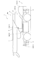
- FIG. 2 shows an example of the aspect of the crane vehicle in work mode.
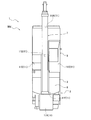
- FIG. 2 shows an example of the aspect of the crane vehicle in work mode.
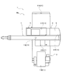
- FIG. 2 shows an example of the aspect of the crane vehicle in work mode.
- FIG. 2 shows an example of the aspect of the crane vehicle in work mode.
- FIG. 2 shows an example of the aspect of the crane vehicle in work mode.
- FIG. 2 shows an example of the aspect of the crane vehicle in work mode.
- working mode was displayed on the display part.
- FIG. 5 and 6 show a state in which only the overhead image P is displayed on the display unit 13 for easy understanding of the overhead image P, the operation unit 14 is also displayed on the display unit 13. And may not necessarily match the actual mode.
- the overhead image system 10 according to the present embodiment will be described with reference to FIGS. 1 to 8.
- the overhead view image system 10 is mounted on a crane vehicle 1 as an example of a work vehicle as shown in FIGS. 1 and 2.
- the crane vehicle 1 includes a traveling body (carrier) 2 and a swivel base 3.
- the traveling body 2 is a main body portion (vehicle body) of a vehicle having a traveling function.
- the traveling body 2 includes a plurality of wheels and a drive source that drives the wheels and the swivel base 3.
- the traveling body 2 has a substantially rectangular shape that is long in the front-rear direction (in FIG. 2, the vertical direction and the upper side is the front side of the traveling body 2) in plan view.
- the traveling body 2 is configured to allow the front side (upper side in FIG. 2) to travel in the vehicle traveling direction, retreat to the rear side (lower side in FIG. 2), and turn left and right by steering. Has been.
- the traveling body 2 is provided with a pair of left and right outriggers 4 (see FIG. 1 (only the left side of the traveling body 2 is shown in FIG. 1)) on the front side and the rear side.
- Each outrigger 4 is configured to be able to extend and retract to the left and right, and by appropriately extending and grounding, the traveling body 2 is stably supported during work using a boom 7 described later (operation mode Mw described later).
- the swivel base 3 is provided on the upper part of the traveling body 2 so as to be horizontally turnable.
- the swivel base 3 includes a cabin 5 and a boom support 6 that can swivel integrally.
- the cabin 5 is a place where an operator (operator) gets on, and the upper side in FIG. 2 is the front side of the cabin 5.
- the cabin 5 is provided with an operation unit for an operator to perform various operations.
- Various operations include, for example, turning of the swivel base 3, raising and lowering and expanding and contracting of a boom 7 described later, winding and lowering of a winch provided on the boom support 6, extension and storage of each outrigger 4, and starting of the engine And stop, traveling of the traveling body 2, and the like.
- the cabin 5 is provided on the right side of the turntable 3 with respect to the vehicle traveling direction (forward movement side).
- the swivel base 3 has such a size that the cabin 5 and the boom support 6 can be accommodated on the traveling body 2.
- the width of the cabin 5 (the dimension in the left-right direction in FIG. 2) is substantially equal to the traveling body 2, and the length dimension (the dimension in the vertical direction in FIG. 2) is smaller than that of the traveling body 2.
- the boom support 6 is a place where the boom 7 is attached.
- the base end of the boom 7 is attached to the boom support 6 via a boom root fulcrum pin.
- the boom 7 can be raised and lowered around the boom fulcrum pin.
- the boom support 6 is provided with a hoisting cylinder (not shown) between the boom support 6 and the boom 7.
- the boom 7 is raised and lowered by extending and retracting the raising and lowering cylinder.
- the boom 7 is arranged on the left side of the cabin 5 in the swivel 3 and extends in the front-rear direction. As shown in FIG. 1, the boom 7 is held in a horizontal posture when not in use such as traveling. The tip of the boom 7 (upper side in FIG. 2) protrudes forward from the traveling body 2.
- the boom 7 may be a so-called slant boom that is held in a posture in which the tip is lowered.
- the boom 7 has a proximal boom portion, an intermediate boom portion, and a distal boom portion that are connected to each other by an extension cylinder.
- the intermediate boom portion and the distal boom portion are accommodated in the base boom portion in a nested manner from the outside to the inside, and are expanded and contracted by extending and contracting the expansion cylinder.
- a sheave is provided at the distal end boom portion, and a wire is wound around the sheave to hang a hook.
- the boom 7 is in a state in which each boom portion is housed when not in use, such as during travel (a travel mode Md (see FIG. 2 or the like) described later).
- the crane vehicle 1 has a travel mode Md and a work mode Mw.
- the traveling mode Md the boom 7 is accommodated as described above, and the front side (vehicle traveling direction) of the traveling body 2 and the front side (front direction) of the cabin 5 (operator therein) in the swivel 3 are matched. In this state (see FIG. 2), this is a mode in which movement by traveling is performed.
- the work mode Mw is a mode in which the traveling is stopped and the swivel base 3 can be swung with respect to the traveling body 2 to use the boom 7 as shown in FIG.
- the crane 1 is in the traveling mode Md when the shift switch is moved forward, neutral, or reverse.
- the crane 1 enters the work mode Mw when a PTO switch for driving a PTO (Power take-off), which is a mechanism for taking out the engine power for driving the vehicle to drive the work machine, is turned on.
- PTO Power take-off
- each outrigger 4 protrudes to the right and left as appropriate and is grounded, and the traveling body 2 is stably supported, so that the boom 3 is appropriately swung around the swivel base 3. 7 can be used.
- An overhead view image system 10 is mounted on the crane vehicle 1.
- the bird's-eye view image system 10 presents a bird's-eye view image P (see FIGS. 5 and 6) showing a state where the crane vehicle 1 is looked down from the upper (upper) virtual viewpoint in the vertical direction.
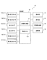
- the overhead image system 10 includes six cameras 11 (11A to 11F), a control unit 12, a display unit 13, an operation unit 14, an information acquisition unit 15, and a storage unit 16.
- Each camera 11 is provided at a predetermined position in view of acquiring an image around the traveling body 2 in the crane vehicle 1 and acquiring an image around the swivel 3 in the crane vehicle 1.
- the camera 11 for example, a wide-angle camera having an angle of view of approximately 180 degrees is used.
- the image of the periphery of the traveling body 2 is an image of the ground (the traveling surface) surrounding the traveling body 2 when viewed from the upper side (above) in the vertical direction, and the traveling body 2 is viewed from the periphery of the traveling body 2. It is an image of the ground in the area up to a predetermined distance from the center (see FIG. 5). Further, the image around the swivel base 3 is basically an image of the ground (traveling surface) surrounding the swivel base 3 when viewed from the upper side (upward) in the vertical direction. It is the image of the ground of the area
- the swivel base 3 is turnable above the traveling body 2, as will be described later, a part of the traveling body 2 may be reflected in an image around the swivel base 3 ( (See FIG. 6).
- the camera 11 has a first front camera 11 ⁇ / b> A that acquires a front image, a first rear camera 11 ⁇ / b> B that acquires a rear image, and a right image as a reference with the traveling body 2. It has a right camera 11C to acquire and a left camera 11D to acquire a left image.
- the first front camera 11A is provided at the end (front end) of the traveling body 2 on the forward side of the traveling body 2
- the first rear camera 11B is the end of the traveling body 2 on the backward side of the traveling body 2 ( It is provided at the rear end.
- the right camera 11 ⁇ / b> C is provided at the right end of the swivel base 3 on the right side of the cabin 5, and the left camera 11 ⁇ / b> D is provided at the left end of the swivel base 3 on the left side of the cabin 5.
- the traveling body 2 has a substantially rectangular shape that is long in the front-rear direction (vehicle traveling direction), even if a wide-angle camera is used, it is necessary to provide only one each on the left and right sides of the traveling body 2. It is difficult to acquire an image over the entire area.
- the crane 1 mounted with the bird's-eye view image system 10 has substantially the same width dimension between the traveling body 2 and the swivel base 3, the front side of the traveling body 2 and the front side of the swivel base 3 (cabin 5). In the traveling mode Md in which the two coincide with each other, both side ends of the turntable 3 substantially coincide with both side ends of the traveling body 2.
- the right camera 11C and the left camera 11D are provided on both sides of the turntable 3, and the installation positions thereof are more than those of the first front camera 11A and the first rear camera 11B provided on the traveling body 2. It is high. As a result, as compared with the case where cameras having the same performance are provided on both sides of the traveling body 2, the front and rear imaging areas are widened. Therefore, both sides of the turntable 3, that is, areas on both sides of the traveling body 2 in the traveling mode Md The images of the right area A3 and the left area A4 (see FIG. 5) can be acquired over the entire area.
- the bird's-eye view image system 10 includes the images of both sides of the traveling body 2 acquired by the right camera 11C and the left camera 11D and the traveling body acquired by the first front camera 11A and the first rear camera 11B in the traveling mode Md. Based on the two front and rear images, a bird's-eye view image P in which the periphery of the traveling body 2 can be viewed over the entire circumference can be generated (see FIG. 5).
- the camera 11 includes a second front camera 11E that acquires a front image and a second rear camera 11F that acquires a rear image with the swivel base 3 as a reference.
- the second front camera 11E is provided at the front end of the swivel base 3 on the front side of the cabin 5, and the second rear camera 11F is provided at the rear end of the swivel base 3 on the back side of the cabin 5.
- the bird's-eye view image system 10 includes images on both sides of the swivel base 3 acquired by the right camera 11C and the left camera 11D, and front and rear sides of the swivel base 3 acquired by the second front camera 11E and the second rear camera 11F.
- control unit 12 is connected to six cameras 11, a display unit 13, an operation unit 14, an information acquisition unit 15, and a storage unit 16.
- the control unit 12 is a microcomputer having a storage unit (internal memory 12a) and a calculation unit.
- the control unit 12 is provided in the cabin 5.
- the control unit 12 controls the operations of the camera 11, the display unit 13, the operation unit 14, the information acquisition unit 15, and the storage unit 16 based on a program stored in the storage unit 16 or the internal memory 12a. Information is appropriately acquired from the operation unit 14 and the information acquisition unit 15.
- the control unit 12 has been performed by the operation unit 14, the generation process of the overhead image P (its image data) based on the signal (image data) from the camera 11, the display process for displaying the overhead image P on the display unit 13, and the operation unit 14. Control of operation determination processing, acquisition processing of various information acquired by the information acquisition unit 15, and the like are performed.
- the control unit 12 generates an overhead image P (image data) from an image (image data) acquired by the camera 11 based on a program stored in the storage unit 16 or the internal memory 12a. 17.
- the image processing unit 17 performs a generation process for generating an overhead image P (image data) by performing the following processes. Note that this generation processing is performed even when a bird's-eye view image Pd (see FIG. 5), which will be described later, is used, except for the difference in the type (11A to 11F) of the camera 11 to be used, the coefficients used, and the like. Since the same applies to the case of (see), it is simply described as an overhead image P.
- the image processing unit 17 performs distortion correction processing for correcting distortion due to the lens by multiplying the coordinate value of the input pixel by a coefficient based on a lens distortion coefficient, an aspect ratio, or the like, and converting it to a coordinate value of the output pixel. Further, the image processing unit 17 sets all the coordinate values of the output pixels by multiplying the coordinate values of the appropriately selected input pixels by various coefficients based on the camera mounting angle and the like, and is set above the crane vehicle 1. An overhead conversion process is performed to convert the captured image (individual overhead image) as viewed from the virtual viewpoint.
- the image processing unit 17 eliminates the sense of discomfort at the joints by performing linear interpolation on the brightness of the corresponding coordinate values, and the adjacent captured images from the cameras 11 that have performed the above-described processes as one image.
- An image composition process for generating the overhead image P by connecting the images is performed.
- the image processing unit 17 switches the camera to be used according to the mode (travel mode Md or work mode Mw) in the crane vehicle 1 and generates the overhead image P.
- the image processing unit 17 images the first front camera 11A, the first rear camera 11B, the right camera 11C, and the left side.
- a traveling bird's-eye view image Pd (see FIG. 5) as the bird's-eye view image P is generated by the above-described processes using the image of the camera 11D. Since the first front camera 11A, the first rear camera 11B, the right camera 11C, and the left camera 11D are arranged in the positional relationship described above, the traveling overhead image Pd is a traveling body as shown in FIG.
- the periphery of 2 is an image continuously projected over the entire circumference.
- the traveling bird's-eye view image Pd includes an image (front image) of the front area A1 in front (forward side) of the traveling body 2 acquired by the first front camera 11A and a rear (reverse) of the traveling body 2 acquired by the first rear camera 11B.
- the image processing unit 17 includes an image of the second front camera 11E, an image of the second rear camera 11F, an image of the right camera 11C, and an image of the left camera 11D.
- a work overhead image Pw (see FIG. 6) as the overhead image P is generated by the above-described processes. Since the second front camera 11E, the second rear camera 11F, the right camera 11C, and the left camera 11D are arranged in the above-described positional relationship, the work overhead image Pw is, as shown in FIG.
- the periphery of 3 is an image continuously projected over the entire circumference.
- the work overhead image Pw includes an image (front image) of the front area A5 in front (front side) of the swivel 3 acquired by the second front camera 11E and a rear (rear surface) of the swivel 3 acquired by the second rear camera 11F.
- the traveling body 2 is partially reflected in the work overhead image Pw.
- the work overhead image Pw shows the traveling body 2 at a position corresponding to the degree of turning of the turntable 3. That is, in the work overhead image Pw, the traveling body 2 is displayed as a part of the peripheral image so as to rotate in the direction opposite to the turning direction of the turntable 3.
- the bird's-eye view images Pd and Pw synthesized in this way become images outside the installation position of the camera 11 in the crane 1 and are inward of the installation position. Image information of the area is missing. That is, the traveling bird's-eye view image Pd becomes an image outside the traveling body 2, and image information of a region where the traveling body 2 exists is missing. The work bird's-eye view image Pw becomes an image outside the swivel base 3, and image information of an area where the swivel base 3 exists is missing. For this reason, the image processing unit 17 sets a missing portion in each of the overhead images Pd and Pw to, for example, a pixel value of zero (black display).
- the image processing unit 17 superimposes a work vehicle sign M (see FIGS. 5 and 6) superimposed on the missing portion of the overhead images Pd and Pw that have been combined to represent the crane vehicle 1 in a simulated manner.
- the work vehicle sign M visualizes and indicates the position and size of the crane vehicle 1 in each overhead view image Pd, Pw. It has a sign part M2 and a swivel sign part M3 showing the swivel 3 including the boom 7 and the like thereon.
- the work vehicle sign M an overhead view photograph of the actual crane vehicle 1 may be used, or a design showing the crane vehicle 1 in an overhead view may be used.
- the image processing unit 17 switches the superimposed work vehicle sign M according to the mode (travel mode Md or work mode Mw) in the crane vehicle 1, that is, the generated overhead image P. Specifically, when the traveling bird's-eye view image Pd is generated in the traveling mode Md, the image processing unit 17 places the traveling body 2 on the traveling body marking unit M2 in the missing region where the traveling body 2 exists, as shown in FIG. The work vehicle sign M on which the swivel sign part M3 is overlapped is superimposed. In the work vehicle sign M at this time, similarly to the crane vehicle 1 (see FIG.
- the image processing unit 17 performs the work performed only from the turntable marker M3 in the missing region where the turntable 3 exists, as shown in FIG. A vehicle sign M is superimposed.
- This is an image of the work bird's-eye view image Pw covering the entire circumference of the periphery of the swivel base 3, and as described above, the traveling body 2 is reflected in the work bird's-eye view image Pw. This is because the swivel base mark portion M3 exists on the traveling body 2 as in the case of the crane vehicle 1.
- the control unit 12 outputs the overhead images Pd and Pw (image data) generated by the image processing unit 17 to the display unit 13 and displays them on the display unit 13 (see FIGS. 5 and 6).
- the images Pd and Pw are stored in the storage unit 16 as appropriate.
- the control unit 12 displays the front side of the traveling body marking unit M2 and the front side of the turntable marking unit M3, and the front areas A1 and A5 in the overhead images Pd and Pw, as viewed from the front of the display unit 13.
- Each of the overhead images Pd and Pw is displayed on the display unit 13.
- the control unit 12 performs a predetermined process based on operation information (data) from the operation unit 14 and various information (data) from the information acquisition unit 15.
- the display unit 13 can display a bird's-eye view image P and various types of information in the crane vehicle 1, and is provided in the cabin 5 of the swivel base 3 in the present embodiment.
- the display unit 13 can display the overhead image P (see FIGS. 5 and 6) generated based on the image acquired by the camera 11 immediately and continuously (in real time) under the control of the control unit 12.
- the display unit 13 has a touch panel function.
- the operation unit 14 is an operation unit for using various functions in the bird's-eye view image system 10, and outputs input information to the control unit 12.
- the operation unit 14 is configured as a screen (such as various icons therein) displayed on the display unit 13 having a touch panel function.
- the operation unit 14 can perform an operation for switching an image to be displayed on the display unit 13, an operation for various settings in the overhead image system 10 and the crane vehicle 1, and the like.
- the operation unit 14 may be provided in the cabin 5 independently of the display unit 13 or may be provided as a switch around the screen of the display unit 13.
- the information acquisition unit 15 acquires various types of operation information regarding the crane 1 and outputs each type of operation information (data) to the control unit 12.
- the operation information includes, for example, mode information indicating whether the crane vehicle 1 is in the traveling mode Md or the work mode Mw, the turning angle of the swivel 3 (boom 7), and the undulation angle and length of the boom 7.
- the attitude information shown is included.
- the information acquisition unit 15 acquires (detects) whether or not the shift switch of the crane vehicle 1 is set to forward, neutral, and reverse as mode information indicating the traveling mode Md. It is acquired (detected) whether or not the PTO switch of the crane 1 is turned on as mode information indicating Mw.
- 11C and the left camera 11D images around the traveling body 2 are acquired separately in front, rear, left, and right, and output to the control unit 12 (image processing unit 17).
- the image processing unit 17 performs each process on the image (image data) acquired by the camera 11 to generate the traveling bird's-eye view image Pd (overhead image P), and the swivel sign on the traveling body marker M2.
- the work vehicle sign M on which the part M3 is superimposed is superimposed on the traveling bird's-eye view image Pd.
- the traveling bird's-eye view image Pd on which the work vehicle sign M is superimposed is displayed on the display unit 13 under the control of the control unit 12 (see FIG. 5). Thereby, the worker can easily visually recognize the periphery of the traveling body 2 in the traveling mode Md of the crane vehicle 1.
- the overhead image system 10 uses the second front camera 11E, the second rear camera 11F, the right camera 11C, and the left camera 11D provided on the turntable 3 when the crane 1 is in the work mode Mw.
- images around the swivel base 3 are acquired separately in front, rear, left, and right, and output to the control unit 12 (image processing unit 17).
- the image processing unit 17 performs each process on the image (image data) acquired by the camera 11 to generate the work overhead image Pw (overhead image P), and the work performed only from the turntable marker M3.
- the vehicle sign M is superimposed on the work overhead image Pw.
- the work overhead image Pw on which the work vehicle sign M is superimposed is displayed on the display unit 13 under the control of the control unit 12 (see FIG. 6). Thereby, the worker can easily visually recognize the periphery of the swivel base 3 in the work mode Mw of the crane vehicle 1.
- the bird's-eye view image system 10 uses the right camera 11C and the left camera 11D provided on the swivel 3 in common regardless of the mode of the crane vehicle 1, and travels according to the mode of the crane vehicle 1.
- the first front camera 11A and the first rear camera 11B provided on the body 2 and the second front camera 11E and the second rear camera 11F provided on the swivel 3 are properly used. That is, the bird's-eye view image system 10 includes the first images acquired by the right camera 11C and the left camera 11D provided on the left and right of the swivel 3 and the first front camera 11A and the first image provided before and after the traveling body 2.
- the second image acquired by the second front camera 11E and the second rear camera 11F provided before and after the rear camera 11B or the swivel base 2 is acquired, and the first image and the second image are combined to form an overhead image.
- An image processing unit 17 to be generated is provided, and the camera that acquires the second image is switched according to the state of the crane vehicle 1 (work vehicle). Thereby, the bird's-eye view image P (running bird's-eye view image Pd, work bird's-eye view image Pw) adapted to the mode can be presented.
- FIG. 7 is a flowchart showing an overhead image display process (overhead image display method) executed by the control unit 12. This overhead image display process is executed by the control unit 12 based on a program stored in the internal memory 12 a or the storage unit 16 of the control unit 12.
- the flowchart in FIG. 7 is started when the overhead image system 10 is in a state of executing the overhead image display process.
- the bird's-eye view image system 10 may always be in a state of executing the bird's-eye view image display process, and may be able to switch whether or not to perform the operation by operating the operation unit 14.
- step S1 the control unit 12 determines whether or not the crane vehicle 1 is in the travel mode Md. If YES, the process proceeds to step S2, and if NO, the process proceeds to step S7.
- step S1 the control unit 12 acquires mode information via the information acquisition unit 15, and determines whether the crane 1 is in the travel mode Md or the work mode Mw based on the acquired mode information. . For example, the control unit 12 determines that the travel mode is Md when the shift switch of the crane 1 is in the forward, neutral, and reverse directions, and the operation is performed when the PTO switch of the crane 1 is in the ON state. It is determined that the mode is Mw.
- step S2 the control unit 12 acquires an image (image data) from the camera 11 corresponding to the travel mode Md, and proceeds to step S3.
- step S2 the control unit 12 displays each image (image data) from the camera 11 corresponding to the travel mode Md, that is, the first front camera 11A, the first rear camera 11B, the right camera 11C, and the left camera 11D. get.
- step S3 the control unit 12 generates a travel overhead image Pd (image data) and proceeds to step S4 (processing as the image processing unit 17).
- step S ⁇ b> 3 a traveling bird's-eye view image Pd (image data) that shows the periphery of the traveling member 2 and lacks image information in a region where the traveling member 2 exists is generated as the bird's-eye view image P.
- step S4 the control unit 12 superimposes the work vehicle sign M corresponding to the travel mode Md on the travel overhead image Pd, and proceeds to step S5 (processing as the image processing unit 17).
- step S4 an image is generated in which the work vehicle sign M corresponding to the travel mode Md, that is, the work vehicle sign M in which the turntable sign part M3 is superimposed on the traveling object sign part M2 is superimposed on the travel overhead image Pd.
- step S5 the control unit 12 causes the display unit 13 to display an image in which the work vehicle sign M corresponding to the travel mode Md is superimposed on the travel overhead image Pd (see FIG. 5), and then proceeds to step S6.
- step S6 the control unit 12 determines whether or not the travel mode Md has ended. If YES, the process proceeds to step S12. If NO, the process returns to step S2.
- step S6 the control part 12 acquires mode information via the information acquisition part 15, and judges whether the crane vehicle 1 complete
- step S7 the control unit 12 acquires an image (image data) from the camera 11 corresponding to the work mode Mw, and proceeds to step S8.
- step S7 since the control unit 12 is not in the travel mode Md, that is, the work mode Mw, the camera 11 corresponding to the work mode Mw, that is, the second front camera 11E, the second rear camera 11F, the right camera 11C, And each image (image data) from the left camera 11D is acquired.
- step S8 the control unit 12 generates a work overhead image Pw (image data) and proceeds to step S9 (processing as the image processing unit 17).
- step S ⁇ b> 8 a work overhead image Pw (image data) that shows the periphery of the swivel base 3 and lacks image information in a region where the swivel base 3 exists is generated as the overhead view image P.
- step S9 the control unit 12 superimposes the work vehicle sign M corresponding to the work mode Mw on the work overhead image Pw, and proceeds to step S10 (processing as the image processing unit 17).
- step S9 an image is generated by superimposing the work vehicle sign M corresponding to the work mode Mw, that is, the work vehicle sign M made only from the turntable mark unit M3, on the work overhead image Pw.
- step S10 the control unit 12 causes the display unit 13 to display an image in which the work vehicle sign M corresponding to the work mode Mw is superimposed on the work overhead image Pw (see FIG. 6), and proceeds to step S11.
- step S11 the control unit 12 determines whether or not the work mode Mw has ended following displaying the work overhead image Pw in step S10 on the display unit 13. If YES, the process proceeds to step S12. If NO, the process returns to step S7.
- step S11 the control part 12 acquires mode information via the information acquisition part 15, and judges whether the crane vehicle 1 complete
- step S12 the control unit 12 determines whether or not to end the overhead image display process. If YES, the overhead image display process is terminated. If NO, the process returns to step S1. In step S12, since the control unit 12 is a scene in which the continued mode (travel mode Md, work mode Mw) is ended, it is determined whether or not the control unit 12 ends the overhead image display processing, that is, on the display unit 13. It is determined whether or not to stop the display of the overhead image P. This determination may be performed based on, for example, the operation of the operation unit 14 or may be performed based on whether the overhead image system 10 is turned off or the crane vehicle 1 is stopped.
- step S2 to S6 determines whether or not to end the bird's-eye view image display process is determined while the travel mode Md is continued (steps S2 to S6) or while the work mode Mw is continued (steps S7 to S11). By doing so, display of the overhead image P can be stopped regardless of the mode of the crane vehicle 1.
- step S1 When the overhead view image system 10 is in a state of executing the overhead view image display process and the crane 1 is in the travel mode Md, the process proceeds from step S1 to step S3 to step S3 in the flowchart of FIG.
- the control unit 12 image processing unit 17
- step S4 by proceeding to step S4 in the flowchart of FIG. 7, the work vehicle sign M in which the swivel sign part M3 is superimposed on the traveling object sign part M2 is superimposed on the travel overhead image Pd, and the process proceeds to step S5.
- step S1 when the overhead view image system 10 is in a state of executing the overhead view image display process and the crane 1 is in the work mode Mw, the process proceeds from step S1 to step S7 to step S8 in the flowchart of FIG.
- the control unit 12 image processing unit 17
- step S9 the work vehicle sign M made only from the turntable sign unit M3
- step S10 the work vehicle sign M is displayed.
- An image superimposed on the work overhead image Pw is displayed on the display unit 13 (see FIG. 6).
- the overhead image system 10 continues the above process until it is determined in step S12 in the flowchart of FIG. 7 that the overhead image display process is terminated.
- the bird's-eye view image system 10 presents the surrounding bird's-eye view image P according to the mode of the crane 1 to the worker via the display unit 13 in real time.
- the bird's-eye view image system 10 changes the mode of the work vehicle sign M superimposed on the bird's-eye view image P according to the mode of the crane vehicle 1, the bird's-eye view image P is in a state close to the state where the actual crane vehicle 1 is seen from above. Is presented to the operator.
- the overhead image system 10 can obtain the following functions and effects.
- the overhead image system 10 is acquired by the first front camera 11A and the first rear camera 11B provided on the traveling body 2, and the right camera 11C and the left camera 11D provided on the turntable 3, respectively.
- a traveling bird's-eye view image Pd (bird's-eye view image P) that is an image around the traveling body 2 is generated using the obtained image. That is, the bird's-eye view image system 10 includes a plurality of cameras 11 that acquire peripheral images of the crane vehicle 1 (work vehicle) provided with the swivel 3 that can turn on the traveling body 2, and images acquired by the plurality of cameras 11.
- a display unit 13 that displays a bird's-eye view image P based thereon, and a control unit 12 that generates the bird's-eye view image P and displays the image on the display unit 13.
- a first front camera 11A that acquires an image
- a first rear camera 11B that is provided on the traveling body 2 and that acquires a rear image of the traveling body 2
- a right that is provided on the swivel base 3 and acquires a right image of the swivel base 3
- a left camera 11D that is provided on the swivel base 3 and acquires a left image of the swivel base 3.
- the overhead view image system 10 can make the installation positions of the right camera 11C and the left camera 11D higher than the first front camera 11A and the first rear camera 11B, and the traveling body 2 can move forward and backward (vehicle traveling direction). ), The images of the regions on both sides of the traveling body 2 can be acquired by one camera, respectively.
- the bird's-eye view image system 10 uses the images from the four cameras 11 (the first front camera 11A, the first rear camera 11B, the right camera 11C, and the left camera 11D), thereby moving back and forth (vehicle traveling direction).
- the overhead image system 10 uses the images acquired by the second front camera 11E, the second rear camera 11F, the right camera 11C, and the left camera 11D provided on the swivel 3 in the work mode Mw.
- a work overhead image Pw (overhead image P), which is an image around 3, is generated.
- the bird's-eye view image system 10 can always acquire the images of the front side, back side, and both sides of the swivel base 3 in the same combination regardless of the turning posture of the swivel base 3 with respect to the traveling body 2.
- the bird's-eye view image system 10 uses the images from the four cameras 11 (the second front camera 11E, the second rear camera 11F, the right camera 11C, and the left camera 11D), so that the traveling body 2 can be used.
- a work overhead image Pw that is an image over the entire circumference of the swivel 3 to be swiveled can be appropriately generated and presented to the operator.
- the bird's-eye view image system 10 uses the right camera 11C and the left camera 11D provided on the swivel 3 in common regardless of the mode of the crane vehicle 1, and the traveling body 2 according to the mode of the crane vehicle 1.
- the first front camera 11 ⁇ / b> A and the first rear camera 11 ⁇ / b> B provided in FIG. 5 and the second front camera 11 ⁇ / b> E and the second rear camera 11 ⁇ / b> F provided on the swivel 3 are properly used.
- the plurality of cameras 11 acquire the rear image of the swivel base 3 provided on the swivel 3 and the second front camera 11 ⁇ / b> E that is provided on the swivel 3 and acquires the front image of the swivel 3.
- the control unit 12 in the traveling mode Md, the image of the first front camera 11A, the image of the first rear camera 11B, the image of the right camera 11C, and the left camera 11D.
- a traveling bird's-eye view image Pd (bird's-eye view image) is generated on the basis of the images of the images, and in the work mode Mw, the image of the second front camera 11E, the image of the second rear camera 11F, the image of the right camera 11C, and the left camera 11D.
- the work overhead view image Pw (overhead view image) is generated based on the image. Therefore, the overhead image system 10 can appropriately generate the traveling overhead image Pd around the traveling body 2 and the work overhead image Pw around the swivel 3 while suppressing an increase in the number of cameras to be used.
- the bird's-eye view image system 10 includes both the driving bird's-eye view image Pd and the work bird's-eye view image Pw by simply switching between the first front camera 11A and the first rear camera 11B, and the second front camera 11E and the second rear camera 11F. Therefore, the traveling overhead image Pd and the work overhead image Pw can be appropriately generated with a simple configuration.
- the bird's-eye view image system 10 superimposes the work vehicle sign M in which the swivel sign part M3 is superimposed on the traveling object sign part M2 on the traveling bird's-eye view image Pd, and the work bird's-eye view image Pw includes only the swivel sign part M3.
- a work vehicle sign M is superimposed. That is, in the bird's-eye view image system 10, in the traveling mode Md, the control unit 12 replaces the traveling body marking unit M2 indicating the traveling body 2 and the turning platform marking unit M3 indicating the swivel 3 with the crane vehicle 1 (work vehicle).
- the work vehicle sign M that is visualized is superimposed on the traveling bird's-eye view image Pd (bird's-eye view image) and displayed on the display unit 13.
- the traveling bird's-eye view image Pd bird's-eye view image
- the traveling overhead image Pd is an image that covers the entire periphery of the traveling vehicle 2.
- the crane vehicle 1 does not move in the work mode Mw, and the swivel base 3 that is swung thereon moves, so that the work overhead image Pw covers the entire periphery of the swivel base 3.
- An image is desirable.
- the second front camera 11E, the second rear camera 11F, the right camera 11C, and the left camera 11D used for the work overhead image Pw are images of the traveling body 2 according to the turning posture of the turntable 3 with respect to the traveling body 2.
- the bird's-eye view image system 10 can generate each bird's-eye view image P required by the worker according to the mode of the crane vehicle 1, and the actual crane while superimposing the work vehicle sign M superimposed thereon on the mode.
- the vehicle 1 can be close to the bird's-eye view.
- the traveling mode Md is superimposed by superimposing the work vehicle sign M with the turntable sign part M3 superimposed on the traveling object sign part M2.
- the overhead view image system 10 displays the periphery of the turntable 3 together with the traveling body 2 in the work overhead view image Pw, by superimposing the work vehicle sign M made only from the turntable mark portion M3, According to the turning posture, the traveling body 2 on the work overhead image Pw turns in the reverse direction with respect to the turntable marking unit M3, and the surroundings of the actual crane vehicle 1 in the work mode Mw are looked down around the turntable 3 as a center. Can be close to For this reason, the bird's-eye view image system 10 can present the bird's-eye view image P that allows the operator to easily and appropriately grasp the surrounding situation without feeling uncomfortable.
- the bird's-eye view image system 10 directs the work vehicle sign M superimposed on the traveling bird's-eye view image Pd to the upper side of the display unit 13 with the front side of the traveling body sign unit M2 and the front side of the swivel mark unit M3 being aligned ( (See FIG. 5). For this reason, the bird's-eye view image system 10 can make the driving bird's-eye view image Pd (see FIG. 5) presented in the driving mode Md closer to the feeling seen by the worker in the cabin 5, and the swivel base sign portion M3. Can be configured in the same manner as the crane vehicle 1 (see FIG. 2) traveling in the traveling mode Md. Thereby, the bird's-eye view image system 10 can make it easier to visually recognize the periphery of the traveling body 2 in the traveling mode Md.
- the bird's-eye view image system 10 has the work vehicle sign M to be superimposed on the work bird's-eye view image Pw facing the front side of the turntable sign unit M3 on the upper side of the display unit 13 (see FIG. 6). For this reason, the bird's-eye view image system 10 can make the work bird's-eye view image Pw (see FIG. 6) presented in the work mode Mw closer to the sensation seen by the worker in the cabin 5, and the swivel marker part M 3. Can be configured in the same manner as the crane vehicle 1 (see FIG. 3) that is driven in the work mode Mw. Thereby, the bird's-eye view image system 10 can make the periphery of the turntable 3 visible more easily in the work mode Mw.
- the periphery of the traveling body 2 provided with the swivel base 3 having the cabin 5 can be made visible over the entire circumference.
- the overhead image system of the present invention has been described based on the embodiment.
- the specific configuration is not limited to the embodiment, and design changes, additions, and the like are possible without departing from the gist of the present invention. Is acceptable.
- the number, position, shape, and the like of the constituent members are not limited to the examples, and the number, position, shape, and the like that are suitable for implementing the present invention can be used.
- the bird's-eye view image system 10 as an example of the bird's-eye view image system according to the present invention has been described.
- a peripheral image of a work vehicle provided with a turntable capable of turning on the traveling body is acquired.
- a control unit that generates and displays the display unit on the display unit, wherein each camera is provided on the traveling body on the forward side of the traveling body and on the traveling body on the backward side of the traveling body.
- a rear camera provided; a right camera provided on the swivel on the right side of the cabin provided on the swivel; and a left camera provided on the swivel on the left side of the cabin.
- a left camera in may be a configured top view image system is not limited to the above embodiment.
- the crane vehicle 1 was shown as a work vehicle using the bird's-eye view image system 10 in the above-described embodiment, if the work vehicle is provided with a turntable (3) capable of turning on the traveling body (2), A work vehicle having another configuration may be used, and is not limited to the above-described embodiment.
- the work vehicle sign M is superimposed on each overhead view image Pd, Pw as shown in FIG. 5 or FIG.
- the overhead images Pd and Pw are partially hidden.
- the tip portion of the boom 7 surrounded by a dotted line corresponds to the place where the bird's-eye view images Pd and Pw are hidden.
- the work bird's-eye view image Pw shown in FIG. 6 a part of the cabin 5 surrounded by a dotted line and about half of the tip side of the boom 7 correspond.
- These hidden locations are locations located outside the traveling body 2 in the swivel base 3 in the traveling bird's-eye view image Pd when the crane vehicle 1 is viewed from above in the vertical direction.
- the front is a position positioned in front of the second front camera 11E in the swivel 3 and the rear and both sides are positions outside the swivel 3.
- the inside of these hidden portions is indicated by lines while the inside is made transparent or semi-transparent, or non-transparent
- the displayed work vehicle sign M may be superimposed on each overhead view image Pd, Pw. This can be executed by processing the display of the hidden part in each overhead view image Pd, Pw and work vehicle sign M.
- the work overhead image Pw is displayed on the display unit 13 in the work mode Mw, but other images may be displayed, and the present invention is not limited to the embodiment.
- a front through image Ps that displays an image acquired by the second front camera 11E without any processing is included.
- the traveling body 2 since the front through image Ps in a state where the swivel base 3 is turned with respect to the traveling body 2 as shown in FIG. 3, the traveling body 2 is not shown in the front through image Ps. However, depending on the rotation posture of the swivel base 3, the traveling body 2 is partially captured.
- the display of the front through image Ps can be switched to the work overhead image Pw to improve usability. Further, both the work overhead image Pw and the front through image Ps may be simultaneously displayed on the display unit 13. Furthermore, the display unit 13 displays (can be switched or simultaneously displayed) as other images, through images acquired by other cameras (11A to 11D, 11F) and images based on the respective cameras (11A to 11F). 8), and is not limited to the example of FIG. The same applies to the traveling mode Md.
Landscapes
- Engineering & Computer Science (AREA)
- Mechanical Engineering (AREA)
- Multimedia (AREA)
- Signal Processing (AREA)
- Mining & Mineral Resources (AREA)
- Civil Engineering (AREA)
- General Engineering & Computer Science (AREA)
- Structural Engineering (AREA)
- Physics & Mathematics (AREA)
- General Physics & Mathematics (AREA)
- Theoretical Computer Science (AREA)
- Automation & Control Theory (AREA)
- Closed-Circuit Television Systems (AREA)
- Component Parts Of Construction Machinery (AREA)
- Fittings On The Vehicle Exterior For Carrying Loads, And Devices For Holding Or Mounting Articles (AREA)
- Jib Cranes (AREA)
- Image Processing (AREA)
- Image Analysis (AREA)
Abstract
キャビンを有する旋回台が設けられた走行体の周辺を全周に亘り視認可能とする俯瞰画像システム、作業車両、俯瞰画像表示方法及びプログラムを提供する。俯瞰画像システムは、作業車両の周辺画像を取得する複数のカメラと、複数のカメラで取得した画像に基づく俯瞰画像を表示する表示部と、俯瞰画像を生成して表示部に表示させる制御部と、を備える。複数のカメラは、走行体に設けられ走行体の前方画像を取得する第1前方カメラと、走行体に設けられ走行体の後方画像を取得する第1後方カメラと、旋回台に設けられ旋回台の右方画像を取得する右方カメラと、旋回台に設けられ旋回台の左方画像を取得する左方カメラと、を有する。
Description
本発明は、作業車両に用いる俯瞰画像システム、俯瞰画像表示方法及びプログラムに関する。
作業車両は、大型であり死角が生じ易く、バックミラー等の位置を工夫しているが、運転席からの周辺の視認が容易ではない。
このため、作業車両では、当該作業車両を中心とした周辺の俯瞰画像を形成して作業者に呈示する俯瞰画像システムを用いることが考えられている(例えば、特許文献1等参照)。この従来の俯瞰画像システムは、車体の周辺を撮影すべく複数のカメラを当該車体に設け、その各カメラで撮影した画像を上方の仮想視点から見下ろした画像に変換しつつ組み合わせて、車体の周辺の俯瞰画像を形成する。このため、従来の俯瞰画像システムは、車体の周辺における運転席からは死角となる位置であっても俯瞰画像に表示することができ、作業車両の安全性を高めることができる。
ところで、作業車両では、走行体の上に旋回可能に旋回台が設けられ、その旋回台にキャビン(運転席)が設けられているものがある。このような作業車両においても、上記した作業車両と同様に、走行体の周辺におけるキャビンからの死角を完全に無くすことは困難であるので、複数のカメラを用いて走行体の周辺の俯瞰画像を形成し、走行体の周辺を全周に亘り視認可能とすることが望ましい。
本発明の目的は、キャビンを有する旋回台が設けられた走行体の周辺を全周に亘り視認可能とする俯瞰画像システム、俯瞰画像表示方法及びプログラムを提供することである。
本発明に係る俯瞰画像システムは、
走行体に旋回可能な旋回台が設けられた作業車両の周辺画像を取得する複数のカメラと、前記複数のカメラで取得した画像に基づく俯瞰画像を表示する表示部と、前記俯瞰画像を生成して前記表示部に表示させる制御部と、を備え、
前記複数のカメラは、前記走行体に設けられ前記走行体の前方画像を取得する第1前方カメラと、前記走行体に設けられ前記走行体の後方画像を取得する第1後方カメラと、前記旋回台に設けられ前記旋回台の右方画像を取得する右方カメラと、前記旋回台に設けられ前記旋回台の左方画像を取得する左方カメラと、を有することを特徴とする。
走行体に旋回可能な旋回台が設けられた作業車両の周辺画像を取得する複数のカメラと、前記複数のカメラで取得した画像に基づく俯瞰画像を表示する表示部と、前記俯瞰画像を生成して前記表示部に表示させる制御部と、を備え、
前記複数のカメラは、前記走行体に設けられ前記走行体の前方画像を取得する第1前方カメラと、前記走行体に設けられ前記走行体の後方画像を取得する第1後方カメラと、前記旋回台に設けられ前記旋回台の右方画像を取得する右方カメラと、前記旋回台に設けられ前記旋回台の左方画像を取得する左方カメラと、を有することを特徴とする。
本発明の俯瞰画像システムは、
走行体に旋回可能な旋回台が設けられた作業車両の周辺の俯瞰画像を表示する俯瞰画像システムであって、
前記旋回台の左右に設けられたカメラで取得した第1画像と、前記走行体又は前記旋回台の前後に設けられたカメラで取得した第2画像とを取得し、前記第1画像と前記第2画像を合成して俯瞰画像を生成する画像処理部、を備え、
前記作業車両の状態に応じて、前記第2画像を取得する前記カメラが切り換えられることを特徴とする。
走行体に旋回可能な旋回台が設けられた作業車両の周辺の俯瞰画像を表示する俯瞰画像システムであって、
前記旋回台の左右に設けられたカメラで取得した第1画像と、前記走行体又は前記旋回台の前後に設けられたカメラで取得した第2画像とを取得し、前記第1画像と前記第2画像を合成して俯瞰画像を生成する画像処理部、を備え、
前記作業車両の状態に応じて、前記第2画像を取得する前記カメラが切り換えられることを特徴とする。
本発明に係る俯瞰画像表示方法は、
走行体に旋回可能な旋回台が設けられた作業車両の周辺の俯瞰画像を表示する俯瞰画像表示方法であって、
前記走行体に設けられ前記走行体の前方画像を取得する第1前方カメラ、前記走行体に設けられ前記走行体の後方画像を取得する第1後方カメラ、前記旋回台に設けられ前記旋回台の右方画像を取得する右方カメラ、及び前記旋回台に設けられ前記旋回台の左方画像を取得する左方カメラから画像を取得する工程と、
前記取得した画像に基づいて前記俯瞰画像を生成して表示する工程と、を含むことを特徴とする。
走行体に旋回可能な旋回台が設けられた作業車両の周辺の俯瞰画像を表示する俯瞰画像表示方法であって、
前記走行体に設けられ前記走行体の前方画像を取得する第1前方カメラ、前記走行体に設けられ前記走行体の後方画像を取得する第1後方カメラ、前記旋回台に設けられ前記旋回台の右方画像を取得する右方カメラ、及び前記旋回台に設けられ前記旋回台の左方画像を取得する左方カメラから画像を取得する工程と、
前記取得した画像に基づいて前記俯瞰画像を生成して表示する工程と、を含むことを特徴とする。
本発明に係るプログラムは、
走行体に旋回可能な旋回台が設けられた作業車両の周辺の俯瞰画像を表示する俯瞰画像システムのコンピューターに、
前記走行体に設けられ前記走行体の前方画像を取得する第1前方カメラ、前記走行体に設けられ前記走行体の後方画像を取得する第1後方カメラ、前記旋回台に設けられ前記旋回台の右方画像を取得する右方カメラ、及び前記旋回台に設けられ前記旋回台の左方画像を取得する左方カメラから画像を取得する処理と、
前記取得した画像に基づいて前記俯瞰画像を生成して表示する処理と、を実現させることを特徴とする。
走行体に旋回可能な旋回台が設けられた作業車両の周辺の俯瞰画像を表示する俯瞰画像システムのコンピューターに、
前記走行体に設けられ前記走行体の前方画像を取得する第1前方カメラ、前記走行体に設けられ前記走行体の後方画像を取得する第1後方カメラ、前記旋回台に設けられ前記旋回台の右方画像を取得する右方カメラ、及び前記旋回台に設けられ前記旋回台の左方画像を取得する左方カメラから画像を取得する処理と、
前記取得した画像に基づいて前記俯瞰画像を生成して表示する処理と、を実現させることを特徴とする。
本発明によれば、キャビンを有する旋回台が設けられた走行体の周辺を全周に亘り視認可能とすることができる。
以下に、本発明に係る俯瞰画像システムを、一例としての作業車両に用いた実施の形態について図面を参照しつつ説明する。なお、図5及び図6は、俯瞰画像Pの理解を容易とすべく表示部13に俯瞰画像Pのみを表示した様子を示しているが、表示部13には操作部14を併せて表示してもよく、必ずしも実際の態様と一致しない。
本実施形態に係る俯瞰画像システム10を、図1から図8を用いて説明する。俯瞰画像システム10は、図1及び図2に示すように、作業車両の一例としてのクレーン車1に搭載される。クレーン車1は、走行体(キャリヤ)2と旋回台3とを備える。
走行体2は、走行機能を有する車両の本体部分(車体)である。走行体2は、複数の車輪と、車輪及び旋回台3を駆動する駆動源と、を有する。走行体2は、図2に示すように、平面視において前後方向(図2では上下方向であり、上側が走行体2の前側である)に長尺な略長方形状を呈する。
走行体2は、前側(図2では上側)を車両進行方向として進行すること、後側(図2では下側)へと後退すること、操舵により左右へと曲がること、を可能とすべく構成されている。走行体2には、前側及び後側に各々左右一対のアウトリガ4(図1参照(図1では走行体2の左側のみ図示))が設けられる。各アウトリガ4は、左右に張り出し及び格納可能に構成され、適宜張り出して接地することで後述するブーム7を用いた作業時(後述する作業モードMw)に走行体2を安定して支持する。
旋回台3は、図1及び図2に示すように、走行体2の上部に水平旋回可能に設けられる。旋回台3は、一体的に旋回可能なキャビン5とブームサポート6とを有する。
キャビン5は、作業者(オペレータ)が乗車する場所であり、図2の上側がキャビン5の正面側である。キャビン5には、作業者が各種の操作を行うための操作部が設けられる。各種の操作としては、例えば、旋回台3の旋回、後述するブーム7の起伏及び伸縮、ブームサポート6に設けられたウインチの巻上及び巻下、各アウトリガ4の張出及び格納、エンジンの始動及び停止、走行体2の走行等がある。本実施の形態では、キャビン5は、車両進行方向(前進側)に対して旋回台3の右側に設けられている。旋回台3は、キャビン5及びブームサポート6が走行体2上に収まる大きさを有する。本実施の形態では、キャビン5の幅寸法(図2の左右方向の寸法)は走行体2と略等しく、長さ寸法(図2の上下方向の寸法)は走行体2よりも小さい。
ブームサポート6は、ブーム7を取り付ける箇所である。ブームサポート6には、ブーム7の基端部がブーム根本支点ピンを介して取り付けられる。ブーム7は、ブーム根本支点ピンを中心にして起伏可能となっている。また、ブームサポート6には、ブーム7との間に起伏用シリンダ(図示略)が設けられる。起伏用シリンダを伸縮することでブーム7が起伏される。
ブーム7は、旋回台3において、キャビン5の左側に配置され、前後方向に延在する。ブーム7は、図1に示すように、走行時等の非使用時において水平姿勢で保持される。ブーム7の先端部(図2の上側)は、走行体2よりも前方に突出する。なお、ブーム7は、先端が下がった姿勢で保持される所謂スラントブームであってもよい。
ブーム7は、内部で伸縮シリンダにより連結された基端ブーム部と中間ブーム部と先端ブーム部とを有する。中間ブーム部と先端ブーム部は、順に基端ブーム部内に外側から内側へと入れ子式に組み合わせて収納され、伸縮シリンダが伸縮することで伸縮する。先端ブーム部にはシーブが設けられ、このシーブにワイヤが掛け回されてフックが吊下げられる。ブーム7は、走行時(後述する走行モードMd(図2等参照))等の非使用時では各ブーム部を収納した状態とされる。
クレーン車1は、走行モードMdと作業モードMwを有する。走行モードMdは、上述したようにブーム7を収納し、走行体2の前側(車両進行方向)と旋回台3におけるキャビン5(その中の作業者)の正面側(正面方向)とを一致させた状態(図2参照)で、走行による移動が行われるモードである。また、作業モードMwは、走行が停止されて、図3に示すように、ブーム7を使用すべく旋回台3を走行体2に対して旋回させることができるモードである。
本実施の形態では、クレーン車1は、シフトスイッチが前進、中立、又は後退とされた場合に走行モードMdとなる。一方、クレーン車1は、車両駆動用のエンジン動力を作業機の駆動のために取り出す機構であるPTO(Power take-off)を駆動させるPTOスイッチがON状態とされた場合に作業モードMwとなる。作業モードMwでは、図3では図示を省略しているが、各アウトリガ4が左右に適宜張り出して接地され、走行体2が安定して支持されることで、旋回台3を適宜旋回しつつブーム7を使用することができる。このクレーン車1に俯瞰画像システム10が搭載されている。
俯瞰画像システム10は、クレーン車1を鉛直方向の上側(上方)の仮想視点から見下ろした様子を示す俯瞰画像P(図5、図6参照)を呈示する。俯瞰画像システム10は、図4に示すように、6つのカメラ11(11A~11F)、制御部12、表示部13、操作部14、情報取得部15、及び記憶部16を備える。各カメラ11は、クレーン車1における走行体2の周辺の画像を取得することと、クレーン車1における旋回台3の周辺の画像を取得することと、を鑑みて、所定の位置に設けられる。カメラ11には、例えば画角が略180度である広角カメラを用いる。
走行体2の周辺の画像とは、鉛直方向の上側(上方)から見て走行体2を取り囲む地面(走行している面)の画像であり、当該走行体2の周縁から当該走行体2を中心とする所定の距離の位置までの領域の地面の画像である(図5参照)。また、旋回台3の周辺の画像とは、基本的に鉛直方向の上側(上方)から見て旋回台3を取り囲む地面(走行している面)の画像であり、当該旋回台3の周縁から当該旋回台3を中心とする所定の距離の位置までの領域の地面の画像である(図6参照)。ここで、旋回台3は、走行体2の上方で旋回可能とされているので、後述するように、旋回台3の周辺の画像には、走行体2の一部が写り込む場合がある(図6参照)。
カメラ11は、図1及び図2に示すように、走行体2を基準として、前方の画像を取得する第1前方カメラ11A、後方の画像を取得する第1後方カメラ11B、右方の画像を取得する右方カメラ11C、及び左方の画像を取得する左方カメラ11Dを有する。第1前方カメラ11Aは、走行体2における前進側で当該走行体2の端部(前端)に設けられ、第1後方カメラ11Bは、走行体2における後退側で当該走行体2の端部(後端)に設けられている。また、右方カメラ11Cは、キャビン5の右側となる旋回台3の右端に設けられ、左方カメラ11Dは、キャビン5の左側となる旋回台3の左端に設けられている。
ここで、走行体2は、前後方向(車両進行方向)に長尺な略長方形状を呈するので、広角カメラを用いても、走行体2の左右に1台ずつ設けただけでは両側の領域の画像を全域に亘り取得するのは困難である。また、俯瞰画像システム10が搭載されたクレーン車1は、走行体2と旋回台3との幅寸法が略等しくなっているので、走行体2の前側と旋回台3(キャビン5)の正面側とが一致している走行モードMdでは、旋回台3における両側端が走行体2の両側端と略一致する。
そこで、本実施の形態では、右方カメラ11C及び左方カメラ11Dを旋回台3の両側に設け、これらの設置位置を走行体2に設けた第1前方カメラ11A及び第1後方カメラ11Bよりも高くしている。これにより、同じ性能のカメラを走行体2の両側に設ける場合に比較して、前後方向の撮影領域が広がるので、旋回台3の両側、すなわち走行モードMdにおける走行体2の両側の領域(後述する右方領域A3及び左方領域A4(図5参照))の画像を全域に亘り取得できる。したがって、俯瞰画像システム10は、走行モードMdにおいて、右方カメラ11C及び左方カメラ11Dが取得した走行体2の両側の画像と、第1前方カメラ11A及び第1後方カメラ11Bが取得した走行体2の前後側の画像とに基づいて、走行体2の周辺を全周に亘って視認可能な俯瞰画像Pを生成することができる(図5参照)。
そこで、本実施の形態では、右方カメラ11C及び左方カメラ11Dを旋回台3の両側に設け、これらの設置位置を走行体2に設けた第1前方カメラ11A及び第1後方カメラ11Bよりも高くしている。これにより、同じ性能のカメラを走行体2の両側に設ける場合に比較して、前後方向の撮影領域が広がるので、旋回台3の両側、すなわち走行モードMdにおける走行体2の両側の領域(後述する右方領域A3及び左方領域A4(図5参照))の画像を全域に亘り取得できる。したがって、俯瞰画像システム10は、走行モードMdにおいて、右方カメラ11C及び左方カメラ11Dが取得した走行体2の両側の画像と、第1前方カメラ11A及び第1後方カメラ11Bが取得した走行体2の前後側の画像とに基づいて、走行体2の周辺を全周に亘って視認可能な俯瞰画像Pを生成することができる(図5参照)。
加えて、カメラ11は、旋回台3を基準として、前方の画像を取得する第2前方カメラ11Eと、後方の画像を取得する第2後方カメラ11Fと、を有する。第2前方カメラ11Eは、キャビン5の正面側となる旋回台3の前端に設けられ、第2後方カメラ11Fは、キャビン5の背面側となる旋回台3の後端に設けられている。このため、俯瞰画像システム10は、右方カメラ11C及び左方カメラ11Dが取得した旋回台3の両側の画像と、第2前方カメラ11E及び第2後方カメラ11Fが取得した旋回台3の前後側の画像とに基づいて、旋回台3の周辺を全周に亘って視認可能な俯瞰画像Pを生成することができる。なお、各カメラ11は、走行体2や旋回台3の周辺の画像を全周に亘り切れ目なく取得するものであれば、詳細な位置は適宜設定すればよく、本実施の形態の構成(図1及び図2に示す位置)に限定されない。
制御部12は、図4に示すように、6つのカメラ11、表示部13、操作部14、情報取得部15、及び記憶部16に接続される。制御部12は、記憶部(内部メモリ12a)や演算部を有するマイクロコンピュータである。本実施の形態では、制御部12は、キャビン5に設けられる。制御部12は、記憶部16あるいは内部メモリ12aに格納されたプログラムに基づき、カメラ11、表示部13、操作部14、情報取得部15及び記憶部16の動作を統括的に制御し、カメラ11、操作部14及び情報取得部15から適宜情報を取得する。制御部12は、カメラ11からの信号(画像データ)に基づく俯瞰画像P(その画像データ)の生成処理や、俯瞰画像Pを表示部13に表示させる表示処理や、操作部14に為された操作の判断処理や、情報取得部15が取得した各種情報の取得処理等の制御を行う。本実施の形態では、制御部12は、記憶部16あるいは内部メモリ12aに格納されたプログラムに基づき、カメラ11が取得した画像(画像データ)から俯瞰画像P(画像データ)を生成する画像処理部17を有する。
画像処理部17は、一例として、次のような各処理を行うことで俯瞰画像P(画像データ)を生成する生成処理を行う。なお、この生成処理は、用いるカメラ11の種類(11A~11F)や用いる係数等が異なることを除くと、後述する走行俯瞰画像Pd(図5参照)であっても作業俯瞰画像Pw(図6参照)であっても同様であるので、単に俯瞰画像Pとして説明する。
先ず、画像処理部17は、入力画素の座標値にレンズ歪み係数やアスペクト比等に基づく係数を乗じて出力画素の座標値に変換することで、レンズによる歪みを補正する歪み補正処理を行う。また、画像処理部17は、適宜選択した入力画素の座標値にカメラ取付角等に基づく種々の係数を乗じて出力画素の全ての座標値を形成することで、クレーン車1の上方に設定した仮想視点から見下ろした撮影画像(個別の俯瞰画像)に変換する俯瞰変換処理を行う。
さらに、画像処理部17は、対応する座標値の輝度を線形補間等することで繋ぎ目の違和感を無くしつつ上記した各処理を行った各カメラ11からの隣り合う撮影画像を1枚の画像として繋ぎ合わせて俯瞰画像Pを生成する画像合成処理を行う。なお、画像処理部17が実行する生成処理では、俯瞰画像P(画像データ)が生成されればよく、前述の各処理が同時に行われてもよいし、他の内容の処理が行われてもよい。
ここで、画像処理部17は、クレーン車1におけるモード(走行モードMdまたは作業モードMw)に応じて、用いるカメラを切り替えて俯瞰画像Pを生成する。
具体的には、画像処理部17は、クレーン車1が走行モードMdとなっている場合、第1前方カメラ11Aの画像、第1後方カメラ11Bの画像、右方カメラ11Cの画像、及び左方カメラ11Dの画像とを用いて、上記した各処理により俯瞰画像Pとしての走行俯瞰画像Pd(図5参照)を生成する。第1前方カメラ11A、第1後方カメラ11B、右方カメラ11C、及び左方カメラ11Dは、上記した位置関係で配置されているので、走行俯瞰画像Pdは、図5に示すように、走行体2の周辺が全周に亘り連続して映し出された画像となる。走行俯瞰画像Pdは、第1前方カメラ11Aが取得した走行体2の前方(前進側)の前方領域A1の画像(前方画像)と、第1後方カメラ11Bが取得した走行体2の後方(後退側)の後方領域A2の画像(後方画像)と、右方カメラ11Cが取得した旋回台3すなわち走行体2の右方(右側)の右方領域A3の画像(右方画像)と、左方カメラ11Dが取得した旋回台3すなわち走行体2の左方(左側)の左方領域A4の画像(左方画像)と、で構成される。
また、画像処理部17は、クレーン車1が作業モードMwとなっている場合、第2前方カメラ11Eの画像、第2後方カメラ11Fの画像、右方カメラ11Cの画像、及び左方カメラ11Dの画像とを用いて、上記した各処理により俯瞰画像Pとしての作業俯瞰画像Pw(図6参照)を生成する。第2前方カメラ11E、第2後方カメラ11F、右方カメラ11C、及び左方カメラ11Dは、上記した位置関係で配置されているので、作業俯瞰画像Pwは、図6に示すように、旋回台3の周辺が全周に亘り連続して映し出された画像となる。作業俯瞰画像Pwは、第2前方カメラ11Eが取得した旋回台3の前方(正面側)の前方領域A5の画像(前方画像)と、第2後方カメラ11Fが取得した旋回台3の後方(背面側)の後方領域A6の画像(後方画像)と、右方カメラ11Cが取得した旋回台3の右方(右側)の右方領域A7の画像(右方画像)と、左方カメラ11Dが取得した旋回台3の左方(左側)の左方領域A8の画像(左方画像)と、で構成される。
このため、作業俯瞰画像Pwには、走行体2が部分的に映る。例えば、図3に示すように、走行体2に対して旋回台3が約90度旋回されている場合、図6に示すように、第2前方カメラ11Eが取得する前方領域A5、右方カメラ11Cが取得する右方領域A7及び左方カメラ11Dが取得する左方領域A8に走行体2が部分的に写る。また、作業俯瞰画像Pwには、旋回台3の旋回の度合いによっては、第2後方カメラ11Fが取得する後方領域A6にも走行体2が部分的に写る。このように、作業俯瞰画像Pwは、旋回台3の旋回の度合いに応じた位置に走行体2を写す。つまり、作業俯瞰画像Pwでは、旋回台3の旋回方向とは逆方向に回転するように、周辺画像の一部として走行体2が表示される。
このように画像合成された各俯瞰画像Pd、Pwは、カメラ11が上記したように設けられているため、クレーン車1におけるカメラ11の設置位置の外方の画像となり当該設置位置の内方の領域の画像情報が欠落する。すなわち、走行俯瞰画像Pdは、走行体2の外方の画像となり、当該走行体2が存在する領域の画像情報が欠落する。作業俯瞰画像Pwは、旋回台3の外方の画像となり、当該旋回台3が存在する領域の画像情報が欠落する。このため、画像処理部17は、各俯瞰画像Pd、Pwにおける欠落箇所を例えば画素値ゼロ(黒表示)とする。
そして、画像処理部17は、画像合成された各俯瞰画像Pd、Pwの欠落箇所に、クレーン車1を模擬的に可視化して表す作業車両標識M(図5、図6参照)を重畳する重畳処理を行う。作業車両標識Mは、図5、図6に示すように、各俯瞰画像Pd、Pwにおけるクレーン車1の位置及び大きさを可視化して示すもので、基本的に、走行体2を示す走行体標識部M2と、その上のブーム7等を含む旋回台3を示す旋回台標識部M3とを有する。作業車両標識Mには、実際のクレーン車1の俯瞰写真を用いてもよいし、クレーン車1を俯瞰して示す図柄を用いてもよい。
ここで、画像処理部17は、クレーン車1におけるモード(走行モードMdまたは作業モードMw)、すなわち生成した俯瞰画像Pに応じて、重畳する作業車両標識Mを切り替える。具体的には、画像処理部17は、走行モードMdで走行俯瞰画像Pdを生成した場合には、図5に示すように、走行体2が存在する欠落領域に、走行体標識部M2上に旋回台標識部M3を重ねた作業車両標識Mを重畳させる。このときの作業車両標識Mでは、走行モードMdであるクレーン車1(図2参照)と同様に、走行体標識部M2の前側(走行体2の前進側に相当する箇所)と旋回台標識部M3の正面側(旋回台3におけるキャビン5の正面側に相当する箇所)とが一致している。
また、画像処理部17は、作業モードMwで作業俯瞰画像Pwを生成した場合には、図6に示すように、旋回台3が存在する欠落領域に、旋回台標識部M3のみから為る作業車両標識Mを重畳させる。これは、作業俯瞰画像Pwが旋回台3の周辺の全周に亘る画像であり、上述したように作業俯瞰画像Pwには走行体2が写り込むので、旋回台標識部M3のみを示せば実際のクレーン車1のように走行体2上に旋回台標識部M3が存在した状態となることによる。
制御部12は、画像処理部17で生成した各俯瞰画像Pd、Pw(画像データ)を、表示部13に出力して当該表示部13に表示(図5、図6参照)させるとともに、各俯瞰画像Pd、Pwを適宜記憶部16に格納する。このとき、制御部12は、走行体標識部M2の前側及び旋回台標識部M3の正面側と、各俯瞰画像Pd、Pwにおける前方領域A1、A5と、を、表示部13を正面視した上側に位置させて、各俯瞰画像Pd、Pwを表示部13に表示させる。このため、キャビン5から見て正面となる前方領域A1、A5及び旋回台標識部M3の正面側が、表示部13の上側に位置して表示されるので、各俯瞰画像Pd、Pwの表示は、キャビン5の中に居る作業者の感覚に一致する。また、制御部12は、操作部14からの操作情報(データ)や、情報取得部15からの各種情報(データ)に基づいて、所定の処理を行う。
表示部13は、俯瞰画像Pやクレーン車1における各種情報を表示可能であり、本実施の形態では旋回台3のキャビン5内に設けられている。表示部13は、制御部12の制御下で、カメラ11で取得された画像に基づき生成された俯瞰画像P(図5、図6参照)を即時連続的に(リアルタイムで)表示できる。表示部13は、本実施の形態では、タッチパネルの機能を搭載する。
操作部14は、俯瞰画像システム10における各種機能を利用するための操作部であり、入力操作された情報を制御部12へと出力する。操作部14は、本実施の形態では、タッチパネルの機能を搭載する表示部13に表示された画面(その中の各種アイコン等)として構成される。操作部14は、表示部13に表示させる画像の切替の操作や、俯瞰画像システム10やクレーン車1における各種の設定の操作等を行うことができる。なお、操作部14は、表示部13とは独立してキャビン5内に設けられてもよく、表示部13の画面の周囲にスイッチとして設けられてもよい。
情報取得部15は、クレーン車1に関する各種の動作情報を取得し、その各動作情報(データ)を制御部12へと出力する。動作情報は、例えば、クレーン車1が走行モードMdであるか作業モードMwであるかの別を示すモード情報や、旋回台3(ブーム7)の旋回角度やブーム7の起伏角度及び長さを示す姿勢情報を含む。情報取得部15は、本実施の形態では、走行モードMdであることを示すモード情報としてクレーン車1のシフトスイッチが前進、中立、後退とされているか否かを取得(検知)し、作業モードMwであることを示すモード情報としてクレーン車1のPTOスイッチがON状態とされているか否かを取得(検知)する。
このように、俯瞰画像システム10では、クレーン車1が走行モードMdである場合に、走行体2に設けた第1前方カメラ11A及び第1後方カメラ11Bと、旋回台3に設けた右方カメラ11C及び左方カメラ11Dとを利用して、走行体2の周辺の画像が前後左右に分けて各々取得され、制御部12(画像処理部17)に出力される。画像処理部17は、上述したように、カメラ11が取得した画像(画像データ)に各処理を行って走行俯瞰画像Pd(俯瞰画像P)を生成し、走行体標識部M2上に旋回台標識部M3を重ねた作業車両標識Mを走行俯瞰画像Pdに重畳させる。作業車両標識Mが重畳された走行俯瞰画像Pdは、制御部12の制御下で表示部13に表示される(図5参照)。これにより、作業者は、クレーン車1の走行モードMdにおいて、走行体2の周辺を容易に視認することができる。
また、俯瞰画像システム10では、クレーン車1が作業モードMwである場合に、旋回台3に設けた第2前方カメラ11E、第2後方カメラ11F、右方カメラ11C及び左方カメラ11Dを利用して、旋回台3の周辺の画像が前後左右に分けて各々取得され、制御部12(画像処理部17)に出力される。画像処理部17は、上述したように、カメラ11が取得した画像(画像データ)に各処理を行って作業俯瞰画像Pw(俯瞰画像P)を生成し、旋回台標識部M3のみから為る作業車両標識Mを作業俯瞰画像Pwに重畳させる。作業車両標識Mが重畳された作業俯瞰画像Pwは、制御部12の制御下で表示部13に表示される(図6参照)。これにより、作業者は、クレーン車1の作業モードMwにおいて、旋回台3の周辺を容易に視認することができる。
このように、俯瞰画像システム10は、クレーン車1のモードに拘わらず旋回台3に設けた右方カメラ11C及び左方カメラ11Dを共通して用いるとともに、クレーン車1のモードに応じて、走行体2に設けた第1前方カメラ11A及び第1後方カメラ11Bと、旋回台3に設けた第2前方カメラ11E及び第2後方カメラ11Fと、を使い分ける。すなわち、俯瞰画像システム10は、旋回台3の左右に設けられた右方カメラ11C及び左方カメラ11Dで取得した第1画像と、走行体2の前後に設けられた第1前方カメラ11A及び第1後方カメラ11B又は旋回台2の前後に設けられた第2前方カメラ11E及び第2後方カメラ11Fで取得した第2画像とを取得し、第1画像と第2画像を合成して俯瞰画像を生成する画像処理部17を備え、クレーン車1(作業車両)の状態に応じて、第2画像を取得するカメラを切り換える。これにより、モードに適応する俯瞰画像P(走行俯瞰画像Pd、作業俯瞰画像Pw)を呈示することができる。
次に、俯瞰画像システム10において、制御部12の制御下で俯瞰画像Pを生成して表示部13に表示させる俯瞰画像表示処理について、図7を用いて説明する。図7は、制御部12にて実行される俯瞰画像表示処理(俯瞰画像表示方法)を示すフローチャートである。この俯瞰画像表示処理は、制御部12の内部メモリ12aもしくは記憶部16に記憶されたプログラムに基づいて、制御部12が実行する。
以下では、図7のフローチャートの各ステップ(各工程)について説明する。図7のフローチャートは、俯瞰画像システム10が俯瞰画像表示処理を実行する状態とされることにより開始される。俯瞰画像システム10は、常に俯瞰画像表示処理を実行する状態とされていてもよく、操作部14の操作で実行の有無を切り替え可能としてもよい。なお、この例では、クレーン車1において走行モードMd及び作業モードMwの2つのモードのみが設定されているものとする。
ステップS1において、制御部12は、クレーン車1が走行モードMdであるか否かを判断し、YESの場合はステップS2へ進み、NOの場合はステップS7へ進む。ステップS1では、制御部12は、情報取得部15を介してモード情報を取得し、取得したモード情報に基づいてクレーン車1が走行モードMdであるか作業モードMwであるかの別を判断する。制御部12は、例えば、クレーン車1のシフトスイッチが前進、中立、後退となっている場合に走行モードMdであると判断し、クレーン車1のPTOスイッチがON状態となっている場合に作業モードMwであると判断する。
ステップS2において、制御部12は、走行モードMdに対応するカメラ11からの画像(画像データ)を取得して、ステップS3へ進む。ステップS2では、制御部12は、走行モードMdに対応するカメラ11、すなわち第1前方カメラ11A、第1後方カメラ11B、右方カメラ11C、及び左方カメラ11Dからの各画像(画像データ)を取得する。
ステップS3において、制御部12は、走行俯瞰画像Pd(画像データ)を生成して、ステップS4へ進む(画像処理部17としての処理)。ステップS3では、走行体2の周辺を示しかつ当該走行体2が存在する領域の画像情報が欠落した走行俯瞰画像Pd(画像データ)が俯瞰画像Pとして生成される。
ステップS4において、制御部12は、走行モードMdに対応する作業車両標識Mを走行俯瞰画像Pdに重畳させて、ステップS5へ進む(画像処理部17としての処理)。ステップS4では、走行モードMdに対応する作業車両標識M、すなわち走行体標識部M2上に旋回台標識部M3を重ねた作業車両標識Mを走行俯瞰画像Pdに重畳した画像が生成される。
ステップS5において、制御部12は、走行モードMdに対応する作業車両標識Mを走行俯瞰画像Pdに重畳させた画像を表示部13に表示させて(図5参照)、ステップS6へ進む。
ステップS6において、制御部12は、走行モードMdが終了したか否かを判断し、YESの場合はステップS12へ進み、NOの場合はステップS2へ戻る。ステップS6では、制御部12は、情報取得部15を介してモード情報を取得し、取得したモード情報に基づいてクレーン車1が走行モードMdを終了したか否かを判断する。制御部12は、例えば、クレーン車1のシフトスイッチが前進、中立、後退から他の状態に移行した場合に走行モードMdを終了したと判断する。
ステップS7において、制御部12は、作業モードMwに対応するカメラ11からの画像(画像データ)を取得して、ステップS8へ進む。ステップS7では、制御部12は、走行モードMdではない、すなわち作業モードMwであるので、作業モードMwに対応するカメラ11、すなわち第2前方カメラ11E、第2後方カメラ11F、右方カメラ11C、及び左方カメラ11Dからの各画像(画像データ)を取得する。
ステップS8において、制御部12は、作業俯瞰画像Pw(画像データ)を生成して、ステップS9へ進む(画像処理部17としての処理)。ステップS8では、旋回台3の周辺を示しかつ当該旋回台3が存在する領域の画像情報が欠落した作業俯瞰画像Pw(画像データ)が俯瞰画像Pとして生成される。
ステップS9において、制御部12は、作業モードMwに対応する作業車両標識Mを作業俯瞰画像Pwに重畳させて、ステップS10へ進む(画像処理部17としての処理)。ステップS9では、作業モードMwに対応する作業車両標識M、すなわち旋回台標識部M3のみから為る作業車両標識Mを作業俯瞰画像Pwに重畳した画像が生成される。
ステップS10において、制御部12は、作業モードMwに対応する作業車両標識Mを作業俯瞰画像Pwに重畳させた画像を表示部13に表示させて(図6参照)、ステップS11へ進む。
ステップS11において、制御部12は、ステップS10での作業俯瞰画像Pwを表示部13に表示させることに続き、作業モードMwが終了したか否かを判断し、YESの場合はステップS12へ進み、NOの場合はステップS7へ戻る。ステップS11では、制御部12は、情報取得部15を介してモード情報を取得し、取得したモード情報に基づいてクレーン車1が作業モードMwを終了したか否かを判断する。制御部12は、例えば、クレーン車1のPTOスイッチがON状態からOFF状態に移行した場合に作業モードMwを終了したと判断する。
ステップS12において、制御部12は、この俯瞰画像表示処理を終了するか否かを判断し、YESの場合は俯瞰画像表示処理を終了し、NOの場合はステップS1へ戻る。ステップS12では、制御部12は、継続されたモード(走行モードMd、作業モードMw)が終了された場面なので、制御部12が俯瞰画像表示処理を終了するか否か、すなわち表示部13での俯瞰画像Pの表示を止めるか否かを判断する。この判断は、例えば、操作部14の操作に基づいて行ってもよく、俯瞰画像システム10の電源が切られることやクレーン車1のエンジンが停止されることに基づいて行ってもよい。なお、この俯瞰画像表示処理を終了するか否かの判断は、走行モードMdが継続されている間(ステップS2からS6)、あるいは、作業モードMwが継続されている間(ステップS7からS11)に行うことで、クレーン車1のモードに拘わらず俯瞰画像Pの表示を止めることができる。
次に、本実施の形態に係る俯瞰画像システム10の動作について説明する。俯瞰画像システム10は、俯瞰画像表示処理を実行する状態とされたときに、クレーン車1が走行モードMdになっていると、図7のフローチャートでステップS1→S2→S3へと進むことで、制御部12(画像処理部17)が走行体2の周辺の走行俯瞰画像Pdを生成する。そして、図7のフローチャートでステップS4へと進むことで、走行体標識部M2上に旋回台標識部M3を重ねた作業車両標識Mを走行俯瞰画像Pdに重畳させ、ステップS5へと進むことで、作業車両標識Mを走行俯瞰画像Pdに重畳した画像を表示部13に表示させる(図5参照)。これらの処理が、図7のフローチャートのステップS6で、クレーン車1の走行モードMdが終了するまで継続される。
また、俯瞰画像システム10は、俯瞰画像表示処理を実行する状態とされたときに、クレーン車1が作業モードMwになっていると、図7のフローチャートでステップS1→S7→S8へと進むことで、制御部12(画像処理部17)が旋回台3の周辺の作業俯瞰画像Pwを生成する。そして、図7のフローチャートでステップS9へと進むことで、旋回台標識部M3のみから為る作業車両標識Mを作業俯瞰画像Pwに重畳させ、ステップS10へと進むことで、作業車両標識Mを作業俯瞰画像Pwに重畳した画像を表示部13に表示させる(図6参照)。これらの処理が、図7のフローチャートのステップS11で、クレーン車1の作業モードMwが終了するまで継続される。
そして、俯瞰画像システム10は、上記したことを、図7のフローチャートのステップS12で、俯瞰画像表示処理を終了すると判断するまで継続する。これにより、俯瞰画像システム10は、クレーン車1のモードに応じた周辺の俯瞰画像Pを、表示部13を介して作業者にリアルタイムで呈示する。また、俯瞰画像システム10は、クレーン車1のモードに応じて、俯瞰画像Pに重畳する作業車両標識Mの態様を変化させるので、実際のクレーン車1を俯瞰した状態に近い状態で俯瞰画像Pを作業者に呈示する。
上記した構成であるため、本発明を適用した実施の形態に係る俯瞰画像システム10は、以下の各作用効果を得られる。
俯瞰画像システム10は、走行モードMdにおいて、走行体2に設けた第1前方カメラ11A及び第1後方カメラ11Bと、旋回台3に設けた右方カメラ11C及び左方カメラ11Dと、が各々取得した画像を用いて走行体2の周辺の画像である走行俯瞰画像Pd(俯瞰画像P)を生成する。すなわち、俯瞰画像システム10は、走行体2に旋回可能な旋回台3が設けられたクレーン車1(作業車両)の周辺画像を取得する複数のカメラ11と、複数のカメラ11で取得した画像に基づく俯瞰画像Pを表示する表示部13と、俯瞰画像Pを生成して表示部13に表示させる制御部12と、を備え、複数のカメラ11は、走行体2に設けられ走行体2の前方画像を取得する第1前方カメラ11Aと、走行体2に設けられ走行体2の後方画像を取得する第1後方カメラ11Bと、旋回台3に設けられ旋回台3の右方画像を取得する右方カメラ11Cと、旋回台3に設けられ旋回台3の左方画像を取得する左方カメラ11Dと、を有する。このため、俯瞰画像システム10は、右方カメラ11C及び左方カメラ11Dの設置位置を第1前方カメラ11A及び第1後方カメラ11Bよりも高くすることができ、走行体2が前後(車両進行方向)に長尺であるにも拘らず当該走行体2の両側の領域の画像を、それぞれ1台のカメラで取得できる。これにより、俯瞰画像システム10は、4つのカメラ11(第1前方カメラ11A、第1後方カメラ11B、右方カメラ11C及び左方カメラ11D)からの画像を用いることで、前後(車両進行方向)に長尺な走行体2の周辺の全周に亘る画像である走行俯瞰画像Pdを適切に生成して作業者に呈示できる。
また、俯瞰画像システム10は、作業モードMwにおいて、旋回台3に設けた第2前方カメラ11E、第2後方カメラ11F、右方カメラ11C及び左方カメラ11Dが各々取得した画像を用いて旋回台3の周辺の画像である作業俯瞰画像Pw(俯瞰画像P)を生成する。このため、俯瞰画像システム10は、走行体2に対する旋回台3の旋回姿勢に拘わらず、旋回台3を基準とした正面側、背面側及び両側の領域の画像を、常に同じ組み合わせで取得できる。これにより、俯瞰画像システム10は、4つのカメラ11(第2前方カメラ11E、第2後方カメラ11F、右方カメラ11C及び左方カメラ11D)からの画像を用いることで、走行体2に対して旋回される旋回台3の周辺の全周に亘る画像である作業俯瞰画像Pwを適切に生成して作業者に呈示できる。
さらに、俯瞰画像システム10は、クレーン車1のモードに拘わらず旋回台3に設けた右方カメラ11C及び左方カメラ11Dを共通して用いるとともに、クレーン車1のモードに応じて、走行体2に設けた第1前方カメラ11A及び第1後方カメラ11Bと、旋回台3に設けた第2前方カメラ11E及び第2後方カメラ11Fと、を使い分けている。すなわち、俯瞰画像システム10において、複数のカメラ11は、旋回台3に設けられ旋回台3の前方画像を取得する第2前方カメラ11Eと、旋回台3に設けられ旋回台3の後方画像を取得する第2後方カメラ11Fと、を有し、制御部12は、走行モードMdでは、第1前方カメラ11Aの画像、第1後方カメラ11Bの画像、右方カメラ11Cの画像、及び左方カメラ11Dの画像に基づいて走行俯瞰画像Pd(俯瞰画像)を生成し、作業モードMwでは、第2前方カメラ11Eの画像、第2後方カメラ11Fの画像、右方カメラ11Cの画像、及び左方カメラ11Dの画像に基づいて作業俯瞰画像Pw(俯瞰画像)を生成する。このため、俯瞰画像システム10は、用いるカメラの台数の増加を抑制しつつ、走行体2の周辺の走行俯瞰画像Pd及び旋回台3の周辺の作業俯瞰画像Pwを適切に生成できる。また、俯瞰画像システム10は、第1前方カメラ11A及び第1後方カメラ11Bと、第2前方カメラ11E及び第2後方カメラ11Fと、を切り替えるだけで走行俯瞰画像Pdと作業俯瞰画像Pwとの双方に対応できるので、簡易な構成で走行俯瞰画像Pd及び作業俯瞰画像Pwを適切に生成できる。
俯瞰画像システム10は、走行俯瞰画像Pdには走行体標識部M2上に旋回台標識部M3を重ねた作業車両標識Mを重畳し、作業俯瞰画像Pwには旋回台標識部M3のみから為る作業車両標識Mを重畳する。すなわち、俯瞰画像システム10において、制御部12は、走行モードMdでは、走行体2を示す走行体標識部M2と旋回台3を示す旋回台標識部M3とを、クレーン車1(作業車両)を可視化して表す作業車両標識Mとして走行俯瞰画像Pd(俯瞰画像)に重畳して表示部13に表示させ、作業モードMwでは、旋回台標識部M3のみを作業車両標識Mとして作業俯瞰画像Pw(俯瞰画像)に重畳して表示部13に表示させる。ここで、クレーン車1は、走行モードMdでは、走行体2が移動するので、走行俯瞰画像Pdは、走行体2の周辺を全周に亘る画像であることが望ましい。また、クレーン車1は、作業モードMwでは、走行体2が移動せず、その上で旋回される旋回台3が移動するので、作業俯瞰画像Pwは、旋回台3の周辺を全周に亘る画像であることが望ましい。そして、作業俯瞰画像Pwに用いる第2前方カメラ11E、第2後方カメラ11F、右方カメラ11C及び左方カメラ11Dは、走行体2に対する旋回台3の旋回姿勢に応じて当該走行体2の画像を部分的に取得する。これらのことから、俯瞰画像システム10は、クレーン車1のモードに応じて作業者が必要とする各俯瞰画像Pを生成でき、それらに重畳する作業車両標識Mを当該モードに応じつつ実際のクレーン車1を俯瞰した状態に近いものにできる。
すなわち、俯瞰画像システム10は、走行俯瞰画像Pdが走行体2の周辺を示すので、走行体標識部M2上に旋回台標識部M3を重ねた作業車両標識Mを重畳することで、走行モードMdにおける実際のクレーン車1の周囲を俯瞰した状態に近いものにできる。また、俯瞰画像システム10は、作業俯瞰画像Pwが旋回台3の周辺を走行体2とともに表示するので、旋回台標識部M3のみから為る作業車両標識Mを重畳することで、旋回台3の旋回姿勢に応じて旋回台標識部M3に対して作業俯瞰画像Pw上の走行体2が逆方向に旋回し、作業モードMwにおける実際のクレーン車1の周囲を旋回台3を中心として俯瞰した状態に近いものにできる。このため、俯瞰画像システム10は、作業者が違和感を覚えることなく周辺の状況を容易かつ適切に把握できる俯瞰画像Pを呈示できる。
俯瞰画像システム10は、走行俯瞰画像Pdに重畳する作業車両標識Mを、走行体標識部M2の前側と旋回台標識部M3の正面側とを一致させつつ表示部13における上側に向けている(図5参照)。このため、俯瞰画像システム10は、走行モードMdで呈示する走行俯瞰画像Pd(図5参照)をキャビン5に居る作業者から見た感覚に近い態様とすることができ、その旋回台標識部M3を走行モードMdで走行するクレーン車1(図2参照)と同様の態様にできる。これにより、俯瞰画像システム10は、走行モードMdにおいて、走行体2の周辺の視認をより容易なものにできる。
俯瞰画像システム10は、作業俯瞰画像Pwに重畳する作業車両標識Mを、旋回台標識部M3の正面側を表示部13における上側に向けている(図6参照)。このため、俯瞰画像システム10は、作業モードMwで呈示する作業俯瞰画像Pw(図6参照)をキャビン5に居る作業者から見た感覚に近い態様とすることができ、その旋回台標識部M3を作業モードMwで駆動するクレーン車1(図3参照)と同様の態様にできる。これにより、俯瞰画像システム10は、作業モードMwにおいて、旋回台3の周辺の視認をより容易なものにできる。
したがって、本発明を適用した実施の形態に係る俯瞰画像システム10では、キャビン5を有する旋回台3が設けられた走行体2の周辺を全周に亘り視認可能とすることができる。
以上、本発明の俯瞰画像システムを実施の形態に基づき説明してきたが、具体的な構成については実施の形態に限られるものではなく、本発明の要旨を逸脱しない限り、設計の変更や追加等は許容される。また、構成部材の数、位置、形状等は実施例に限定されず、本発明を実施する上で好適な数、位置、形状等にできる。
なお、上記した実施の形態では、本発明に係る俯瞰画像システムの一実施例としての俯瞰画像システム10について説明したが、走行体に旋回可能な旋回台が設けられた作業車両の周辺画像を取得する複数のカメラと、前記各カメラで取得した画像に基づく俯瞰画像を表示する表示部と、前記各カメラで取得した画像を上方の仮想視点から見下ろした画像に変換し繋ぎ合わせて前記俯瞰画像を生成して前記表示部に表示させる制御部と、を備え、前記各カメラは、前記走行体における前進側で前記走行体に設けられた前方カメラと、前記走行体における後退側で前記走行体に設けられた後方カメラと、前記旋回台に設けられたキャビンにおける右側で前記旋回台に設けられた右方カメラと、前記キャビンにおける左側で前記旋回台に設けられた左方カメラと、で構成される俯瞰画像システムであればよく、上記した実施の形態に限定されない。
また、上記した実施の形態では俯瞰画像システム10を用いる作業車両としてクレーン車1を示していたが、走行体(2)に旋回可能な旋回台(3)が設けられた作業車両であれば、他の構成の作業車両でもよく、上記した実施の形態に限定されない。
さらに、上記した実施の形態では、図5または図6に示すように各俯瞰画像Pd、Pwに作業車両標識Mを重畳させていたが、各カメラ11の設置位置によっては作業車両標識Mが各俯瞰画像Pd、Pwを部分的に隠してしまう場合がある。各俯瞰画像Pd、Pwを隠す箇所としては、例えば、図5に示す走行俯瞰画像Pdでは、点線で囲んだブーム7の先端箇所が該当する。図6に示す作業俯瞰画像Pwでは、点線で囲んだキャビン5の一部及びブーム7の先端側の約半分が該当する。これらの隠す箇所は、クレーン車1を鉛直方向上側から見た状態において、走行俯瞰画像Pdでは、旋回台3における走行体2よりも外側に位置する箇所である。作業俯瞰画像Pwでは、前方が旋回台3における第2前方カメラ11Eよりも前方に位置する箇所でかつ後方及び両側方が旋回台3よりも外側に位置する箇所である。このため、俯瞰画像システム10では、各俯瞰画像Pd、Pwを全周に亘り切れ目なく視認させるべく、これらの隠す箇所の外形を線で示しつつその内側を透明としたり半透明化したり、または非表示としたりした作業車両標識Mを各俯瞰画像Pd、Pwに重畳させてもよい。このことは、各俯瞰画像Pd、Pw及び作業車両標識Mにおける隠す箇所の表示を加工することで実行できる。
上記した実施の形態では、作業モードMwにおいて作業俯瞰画像Pwを表示部13に表示させていたが、他の画像を表示させてもよく、実施の形態に限定されない。その他の表示としては、例えば、図8に示すように、第2前方カメラ11Eで取得した画像を何らの加工を施さないで表示する前方スルー画像Psが挙げられる。図8に示す例では、図3に示すように旋回台3を走行体2に対して旋回させた状態の前方スルー画像Psであるので、この前方スルー画像Psには走行体2は写っていないが、旋回台3の回転姿勢によっては走行体2が部分的に写ることとなる。このように前方スルー画像Psを表示することで、作業者の正面ではあってもキャビン5からは死角となる箇所を視認できるので、前方の状況の容易かつ適切な把握が可能となる。この前方スルー画像Psの表示は、作業俯瞰画像Pwと切り替え可能とすることで使い勝手を向上できる。また、作業俯瞰画像Pwと前方スルー画像Psとの双方を同時に表示部13に表示させることとしてもよい。さらに、表示部13は、他の画像として、他のカメラ(11A~11D、11F)で取得したスルー画像や各カメラ(11A~11F)に基づく画像を表示(切り替え可能とすることや同時に表示させることも含む)させるものとしてもよく、図8の例に限定されない。これらのことは、走行モードMdであっても同様である。
2016年9月9日出願の特願2016-176872の日本出願に含まれる明細書、図面及び要約書の開示内容は、すべて本願に援用される。
1 (作業車両の一例としての)クレーン車
2 走行体
3 旋回台
5 キャビン
10 俯瞰画像システム
11 カメラ
11A 第1前方カメラ
11B 第1後方カメラ
11C 右方カメラ
11D 左方カメラ
11E 第2前方カメラ
11F 第2後方カメラ
12 制御部
13 表示部
M 作業車両標識
M2 走行体標識部
M3 旋回台標識部
Md 走行モード
Mw 作業モード
P 俯瞰画像
Pd 走行俯瞰画像
Pw 作業俯瞰画像
2 走行体
3 旋回台
5 キャビン
10 俯瞰画像システム
11 カメラ
11A 第1前方カメラ
11B 第1後方カメラ
11C 右方カメラ
11D 左方カメラ
11E 第2前方カメラ
11F 第2後方カメラ
12 制御部
13 表示部
M 作業車両標識
M2 走行体標識部
M3 旋回台標識部
Md 走行モード
Mw 作業モード
P 俯瞰画像
Pd 走行俯瞰画像
Pw 作業俯瞰画像
Claims (7)
- 走行体に旋回可能な旋回台が設けられた作業車両の周辺画像を取得する複数のカメラと、前記複数のカメラで取得した画像に基づく俯瞰画像を表示する表示部と、前記俯瞰画像を生成して前記表示部に表示させる制御部と、を備え、
前記複数のカメラは、前記走行体に設けられ前記走行体の前方画像を取得する第1前方カメラと、前記走行体に設けられ前記走行体の後方画像を取得する第1後方カメラと、前記旋回台に設けられ前記旋回台の右方画像を取得する右方カメラと、前記旋回台に設けられ前記旋回台の左方画像を取得する左方カメラと、を有することを特徴とする俯瞰画像システム。 - 前記作業車両は、前記走行体の前進方向と前記旋回台に設けられたキャビンの正面方向とが一致した状態で走行する走行モードと、前記走行体に対して前記旋回台を旋回可能な作業モードと、を有し、
前記複数のカメラは、さらに、前記旋回台に設けられ前記旋回台の前方画像を取得する第2前方カメラと、前記旋回台に設けられ前記旋回台の後方画像を取得する第2後方カメラと、を有し、
前記制御部は、前記走行モードでは、前記第1前方カメラの画像、前記第1後方カメラの画像、前記右方カメラの画像、及び前記左方カメラの画像に基づいて前記俯瞰画像を生成し、前記作業モードでは、前記第2前方カメラの画像、前記第2後方カメラの画像、前記右方カメラの画像、及び前記左方カメラの画像に基づいて前記俯瞰画像を生成することを特徴とする請求項1に記載の俯瞰画像システム。 - 前記制御部は、前記走行モードでは、前記走行体を示す走行体標識部と前記旋回台を示す旋回台標識部とを、前記作業車両を可視化して表す作業車両標識として前記俯瞰画像に重畳して前記表示部に表示させ、前記作業モードでは、前記旋回台標識部のみを前記作業車両標識として前記俯瞰画像に重畳して前記表示部に表示させることを特徴とする請求項2に記載の俯瞰画像システム。
- 前記制御部は、前記走行体標識部における前記走行体の前進側に相当する箇所を前記表示部での上側に向けて前記走行体標識部を表示させ、前記旋回台標識部における前記旋回台における前記キャビンの正面側に相当する箇所を前記表示部での上側に向けて前記旋回台標識部を表示させることを特徴とする請求項3に記載の俯瞰画像システム。
- 走行体に旋回可能な旋回台が設けられた作業車両の周辺の俯瞰画像を表示する俯瞰画像システムであって、
前記旋回台の左右に設けられたカメラで取得した第1画像と、前記走行体又は前記旋回台の前後に設けられたカメラで取得した第2画像とを取得し、前記第1画像と前記第2画像を合成して俯瞰画像を生成する画像処理部、を備え、
前記作業車両の状態に応じて、前記第2画像を取得する前記カメラが切り換えられることを特徴とする俯瞰画像システム。 - 走行体に旋回可能な旋回台が設けられた作業車両の周辺の俯瞰画像を表示する俯瞰画像表示方法であって、
前記走行体に設けられ前記走行体の前方画像を取得する第1前方カメラ、前記走行体に設けられ前記走行体の後方画像を取得する第1後方カメラ、前記旋回台に設けられ前記旋回台の右方画像を取得する右方カメラ、及び前記旋回台に設けられ前記旋回台の左方画像を取得する左方カメラから画像を取得する工程と、
前記取得した画像に基づいて前記俯瞰画像を生成して表示する工程と、を含むことを特徴とする俯瞰画像表示方法。 - 走行体に旋回可能な旋回台が設けられた作業車両の周辺の俯瞰画像を表示する俯瞰画像システムのコンピューターに、
前記走行体に設けられ前記走行体の前方画像を取得する第1前方カメラ、前記走行体に設けられ前記走行体の後方画像を取得する第1後方カメラ、前記旋回台に設けられ前記旋回台の右方画像を取得する右方カメラ、及び前記旋回台に設けられ前記旋回台の左方画像を取得する左方カメラから画像を取得する処理と、
前記取得した画像に基づいて前記俯瞰画像を生成して表示する処理と、を実現させることを特徴とするプログラム。
Priority Applications (3)
| Application Number | Priority Date | Filing Date | Title |
|---|---|---|---|
| EP17848892.0A EP3512194B1 (en) | 2016-09-09 | 2017-09-08 | Bird's-eye view image system, bird's-eye view image display method and program |
| US16/329,420 US10661712B2 (en) | 2016-09-09 | 2017-09-08 | Bird's-eye view image system, bird's-eye view image display method and program |
| CN201780053672.0A CN109661813B (zh) | 2016-09-09 | 2017-09-08 | 俯瞰图像系统、俯瞰图像显示方法以及存储有程序的计算机可读取的记录介质 |
Applications Claiming Priority (2)
| Application Number | Priority Date | Filing Date | Title |
|---|---|---|---|
| JP2016-176872 | 2016-09-09 | ||
| JP2016176872A JP6756555B2 (ja) | 2016-09-09 | 2016-09-09 | 俯瞰画像システム、俯瞰画像表示方法およびプログラム |
Publications (1)
| Publication Number | Publication Date |
|---|---|
| WO2018047954A1 true WO2018047954A1 (ja) | 2018-03-15 |
Family
ID=61562325
Family Applications (1)
| Application Number | Title | Priority Date | Filing Date |
|---|---|---|---|
| PCT/JP2017/032534 Ceased WO2018047954A1 (ja) | 2016-09-09 | 2017-09-08 | 俯瞰画像システム、俯瞰画像表示方法及びプログラム |
Country Status (5)
| Country | Link |
|---|---|
| US (1) | US10661712B2 (ja) |
| EP (1) | EP3512194B1 (ja) |
| JP (1) | JP6756555B2 (ja) |
| CN (1) | CN109661813B (ja) |
| WO (1) | WO2018047954A1 (ja) |
Cited By (2)
| Publication number | Priority date | Publication date | Assignee | Title |
|---|---|---|---|---|
| JPWO2020218455A1 (ja) * | 2019-04-26 | 2020-10-29 | ||
| WO2020256101A1 (ja) * | 2019-06-20 | 2020-12-24 | 株式会社タダノ | 画像システムおよび画像システムを備える作業車両 |
Families Citing this family (12)
| Publication number | Priority date | Publication date | Assignee | Title |
|---|---|---|---|---|
| KR102707140B1 (ko) * | 2017-12-27 | 2024-09-13 | 스미토모 겐키 가부시키가이샤 | 쇼벨 및 쇼벨의 출력장치 |
| JP6607272B2 (ja) * | 2018-03-02 | 2019-11-20 | 株式会社Jvcケンウッド | 車両用記録装置、車両用記録方法及びプログラム |
| JP7147248B2 (ja) | 2018-04-27 | 2022-10-05 | 株式会社タダノ | クレーン車 |
| JP7059956B2 (ja) * | 2019-02-08 | 2022-04-26 | コベルコ建機株式会社 | 建設機械の障害物検出装置 |
| JP7518664B2 (ja) * | 2020-05-27 | 2024-07-18 | 株式会社アイチコーポレーション | 作業車 |
| JP7620396B2 (ja) | 2020-05-27 | 2025-01-23 | 株式会社アイチコーポレーション | 作業車 |
| CN112019752A (zh) * | 2020-09-11 | 2020-12-01 | 三一汽车起重机械有限公司 | 一种全景监控方法、全景监控系统及起重机 |
| US12195306B2 (en) | 2021-04-12 | 2025-01-14 | Structural Services, Inc. | Systems and methods for identifying and locating building material objects |
| AU2022258326A1 (en) | 2021-04-12 | 2023-11-23 | Structural Services, Inc. | Systems and methods for assisting a crane operator |
| CN113225527A (zh) * | 2021-04-14 | 2021-08-06 | 三一海洋重工有限公司 | 一种全景视频监控方法、装置及一种工程设备 |
| JP2023082954A (ja) * | 2021-12-03 | 2023-06-15 | 本田技研工業株式会社 | 制御装置、制御方法、及び制御プログラム |
| US20240308830A1 (en) * | 2023-03-13 | 2024-09-19 | Oshkosh Corporation | Systems and methods for direction of travel |
Citations (7)
| Publication number | Priority date | Publication date | Assignee | Title |
|---|---|---|---|---|
| JP2010059653A (ja) * | 2008-09-02 | 2010-03-18 | Hitachi Constr Mach Co Ltd | 作業機械の視野補助装置 |
| JP2011151742A (ja) * | 2010-01-25 | 2011-08-04 | Tadano Ltd | 画像表示システム |
| JP2012107395A (ja) * | 2010-11-15 | 2012-06-07 | Sumitomo (Shi) Construction Machinery Co Ltd | 建設機械のモニター装置 |
| JP2013121056A (ja) * | 2011-12-07 | 2013-06-17 | Fujitsu Ten Ltd | 画像処理装置、車両、画像処理方法、及び、プログラム |
| JP2015139158A (ja) * | 2014-01-23 | 2015-07-30 | クラリオン株式会社 | 重機用周辺監視装置 |
| WO2015125979A1 (ja) * | 2015-04-28 | 2015-08-27 | 株式会社小松製作所 | 作業機械の周辺監視装置及び作業機械の周辺監視方法 |
| JP2016030891A (ja) * | 2014-07-25 | 2016-03-07 | 日立建機株式会社 | 旋回式作業機の周囲表示装置 |
Family Cites Families (5)
| Publication number | Priority date | Publication date | Assignee | Title |
|---|---|---|---|---|
| US7448812B2 (en) * | 2004-05-27 | 2008-11-11 | Heibel Thomas S | Camera mount |
| JP4934308B2 (ja) * | 2005-10-17 | 2012-05-16 | 三洋電機株式会社 | 運転支援システム |
| CN101442618A (zh) * | 2008-12-31 | 2009-05-27 | 葛晨阳 | 用于车辆辅助驾驶的360度环形视频合成方法 |
| CN102175222B (zh) * | 2011-03-04 | 2012-09-05 | 南开大学 | 基于立体视觉的吊车避障系统 |
| JP6313992B2 (ja) * | 2014-02-18 | 2018-04-18 | クラリオン株式会社 | 牽引車用周囲監視装置 |
-
2016
- 2016-09-09 JP JP2016176872A patent/JP6756555B2/ja active Active
-
2017
- 2017-09-08 US US16/329,420 patent/US10661712B2/en active Active
- 2017-09-08 CN CN201780053672.0A patent/CN109661813B/zh active Active
- 2017-09-08 WO PCT/JP2017/032534 patent/WO2018047954A1/ja not_active Ceased
- 2017-09-08 EP EP17848892.0A patent/EP3512194B1/en active Active
Patent Citations (7)
| Publication number | Priority date | Publication date | Assignee | Title |
|---|---|---|---|---|
| JP2010059653A (ja) * | 2008-09-02 | 2010-03-18 | Hitachi Constr Mach Co Ltd | 作業機械の視野補助装置 |
| JP2011151742A (ja) * | 2010-01-25 | 2011-08-04 | Tadano Ltd | 画像表示システム |
| JP2012107395A (ja) * | 2010-11-15 | 2012-06-07 | Sumitomo (Shi) Construction Machinery Co Ltd | 建設機械のモニター装置 |
| JP2013121056A (ja) * | 2011-12-07 | 2013-06-17 | Fujitsu Ten Ltd | 画像処理装置、車両、画像処理方法、及び、プログラム |
| JP2015139158A (ja) * | 2014-01-23 | 2015-07-30 | クラリオン株式会社 | 重機用周辺監視装置 |
| JP2016030891A (ja) * | 2014-07-25 | 2016-03-07 | 日立建機株式会社 | 旋回式作業機の周囲表示装置 |
| WO2015125979A1 (ja) * | 2015-04-28 | 2015-08-27 | 株式会社小松製作所 | 作業機械の周辺監視装置及び作業機械の周辺監視方法 |
Cited By (8)
| Publication number | Priority date | Publication date | Assignee | Title |
|---|---|---|---|---|
| JPWO2020218455A1 (ja) * | 2019-04-26 | 2020-10-29 | ||
| WO2020218455A1 (ja) * | 2019-04-26 | 2020-10-29 | 住友建機株式会社 | ショベル |
| JP7407178B2 (ja) | 2019-04-26 | 2023-12-28 | 住友建機株式会社 | ショベル |
| US12252868B2 (en) | 2019-04-26 | 2025-03-18 | Sumitomo Construction Machinery Co., Ltd. | Shovel |
| WO2020256101A1 (ja) * | 2019-06-20 | 2020-12-24 | 株式会社タダノ | 画像システムおよび画像システムを備える作業車両 |
| JPWO2020256101A1 (ja) * | 2019-06-20 | 2020-12-24 | ||
| EP3988491A4 (en) * | 2019-06-20 | 2023-08-02 | Tadano Ltd. | IMAGE SYSTEM AND CONSTRUCTION MACHINE PROVIDED WITH THE IMAGE SYSTEM |
| US12187584B2 (en) | 2019-06-20 | 2025-01-07 | Tadano Ltd. | Image system and work vehicle provided with image system |
Also Published As
| Publication number | Publication date |
|---|---|
| CN109661813A (zh) | 2019-04-19 |
| EP3512194A4 (en) | 2020-04-01 |
| EP3512194A1 (en) | 2019-07-17 |
| JP6756555B2 (ja) | 2020-09-16 |
| US10661712B2 (en) | 2020-05-26 |
| CN109661813B (zh) | 2020-10-02 |
| US20190248289A1 (en) | 2019-08-15 |
| EP3512194B1 (en) | 2021-04-21 |
| JP2018042207A (ja) | 2018-03-15 |
Similar Documents
| Publication | Publication Date | Title |
|---|---|---|
| WO2018047954A1 (ja) | 俯瞰画像システム、俯瞰画像表示方法及びプログラム | |
| JP5814187B2 (ja) | 自走式産業機械の表示装置 | |
| JP5462008B2 (ja) | 画像表示システム | |
| JP5068779B2 (ja) | 車両周囲俯瞰画像表示装置及び方法 | |
| JP6589468B2 (ja) | 移動式クレーンの周囲表示装置 | |
| JP5914013B2 (ja) | 運転支援装置 | |
| JP5775283B2 (ja) | 作業機械のモニタ装置 | |
| JP2012051678A (ja) | 視界補助システム | |
| JP6321977B2 (ja) | 重機用周辺監視装置 | |
| WO2013183536A1 (ja) | 自走式産業機械の表示装置 | |
| JP2008312004A (ja) | カメラシステム及び機械装置 | |
| CN103797789A (zh) | 工作机械的周围监视装置 | |
| JP5251804B2 (ja) | 運転支援装置 | |
| JP2001163132A (ja) | 車両後方監視装置用画像変換装置 | |
| WO2013172172A1 (ja) | 自走式産業機械の表示装置 | |
| JP5841821B2 (ja) | 画像処理装置、車両、画像処理方法、及び、プログラム | |
| JP5066198B2 (ja) | 作業機械のモニタ装置 | |
| JP5776995B2 (ja) | 車両用周辺監視装置 | |
| JP5996879B2 (ja) | 作業機械の周囲監視装置 | |
| JP6713884B2 (ja) | 俯瞰画像システム、俯瞰画像表示方法およびプログラム | |
| JP6139740B2 (ja) | 作業機械の周囲監視装置 | |
| JP6756554B2 (ja) | 画像表示システム | |
| JP2018039648A (ja) | 画像表示システム | |
| JP2018039477A (ja) | 画像表示システム | |
| JP2012001126A (ja) | 車両用周辺監視装置 |
Legal Events
| Date | Code | Title | Description |
|---|---|---|---|
| 121 | Ep: the epo has been informed by wipo that ep was designated in this application |
Ref document number: 17848892 Country of ref document: EP Kind code of ref document: A1 |
|
| NENP | Non-entry into the national phase |
Ref country code: DE |
|
| ENP | Entry into the national phase |
Ref document number: 2017848892 Country of ref document: EP Effective date: 20190409 |