WO2018047954A1 - Système d'image de vue à vol d'oiseau, procédé d'affichage d'image de vue à vol d'oiseau et programme - Google Patents
Système d'image de vue à vol d'oiseau, procédé d'affichage d'image de vue à vol d'oiseau et programme Download PDFInfo
- Publication number
- WO2018047954A1 WO2018047954A1 PCT/JP2017/032534 JP2017032534W WO2018047954A1 WO 2018047954 A1 WO2018047954 A1 WO 2018047954A1 JP 2017032534 W JP2017032534 W JP 2017032534W WO 2018047954 A1 WO2018047954 A1 WO 2018047954A1
- Authority
- WO
- WIPO (PCT)
- Prior art keywords
- image
- traveling body
- camera
- bird
- eye view
- Prior art date
- Legal status (The legal status is an assumption and is not a legal conclusion. Google has not performed a legal analysis and makes no representation as to the accuracy of the status listed.)
- Ceased
Links
Images


Classifications
-
- B—PERFORMING OPERATIONS; TRANSPORTING
- B66—HOISTING; LIFTING; HAULING
- B66C—CRANES; LOAD-ENGAGING ELEMENTS OR DEVICES FOR CRANES, CAPSTANS, WINCHES, OR TACKLES
- B66C13/00—Other constructional features or details
- B66C13/18—Control systems or devices
- B66C13/46—Position indicators for suspended loads or for crane elements
-
- B—PERFORMING OPERATIONS; TRANSPORTING
- B60—VEHICLES IN GENERAL
- B60R—VEHICLES, VEHICLE FITTINGS, OR VEHICLE PARTS, NOT OTHERWISE PROVIDED FOR
- B60R1/00—Optical viewing arrangements; Real-time viewing arrangements for drivers or passengers using optical image capturing systems, e.g. cameras or video systems specially adapted for use in or on vehicles
- B60R1/20—Real-time viewing arrangements for drivers or passengers using optical image capturing systems, e.g. cameras or video systems specially adapted for use in or on vehicles
- B60R1/22—Real-time viewing arrangements for drivers or passengers using optical image capturing systems, e.g. cameras or video systems specially adapted for use in or on vehicles for viewing an area outside the vehicle, e.g. the exterior of the vehicle
- B60R1/23—Real-time viewing arrangements for drivers or passengers using optical image capturing systems, e.g. cameras or video systems specially adapted for use in or on vehicles for viewing an area outside the vehicle, e.g. the exterior of the vehicle with a predetermined field of view
- B60R1/27—Real-time viewing arrangements for drivers or passengers using optical image capturing systems, e.g. cameras or video systems specially adapted for use in or on vehicles for viewing an area outside the vehicle, e.g. the exterior of the vehicle with a predetermined field of view providing all-round vision, e.g. using omnidirectional cameras
-
- B—PERFORMING OPERATIONS; TRANSPORTING
- B60—VEHICLES IN GENERAL
- B60R—VEHICLES, VEHICLE FITTINGS, OR VEHICLE PARTS, NOT OTHERWISE PROVIDED FOR
- B60R11/00—Arrangements for holding or mounting articles, not otherwise provided for
- B60R11/02—Arrangements for holding or mounting articles, not otherwise provided for for radio sets, television sets, telephones, or the like; Arrangement of controls thereof
-
- B—PERFORMING OPERATIONS; TRANSPORTING
- B60—VEHICLES IN GENERAL
- B60R—VEHICLES, VEHICLE FITTINGS, OR VEHICLE PARTS, NOT OTHERWISE PROVIDED FOR
- B60R11/00—Arrangements for holding or mounting articles, not otherwise provided for
- B60R11/04—Mounting of cameras operative during drive; Arrangement of controls thereof relative to the vehicle
-
- B—PERFORMING OPERATIONS; TRANSPORTING
- B66—HOISTING; LIFTING; HAULING
- B66C—CRANES; LOAD-ENGAGING ELEMENTS OR DEVICES FOR CRANES, CAPSTANS, WINCHES, OR TACKLES
- B66C13/00—Other constructional features or details
-
- B—PERFORMING OPERATIONS; TRANSPORTING
- B66—HOISTING; LIFTING; HAULING
- B66C—CRANES; LOAD-ENGAGING ELEMENTS OR DEVICES FOR CRANES, CAPSTANS, WINCHES, OR TACKLES
- B66C23/00—Cranes comprising essentially a beam, boom, or triangular structure acting as a cantilever and mounted for translatory of swinging movements in vertical or horizontal planes or a combination of such movements, e.g. jib-cranes, derricks, tower cranes
- B66C23/88—Safety gear
- B66C23/90—Devices for indicating or limiting lifting moment
-
- B—PERFORMING OPERATIONS; TRANSPORTING
- B66—HOISTING; LIFTING; HAULING
- B66C—CRANES; LOAD-ENGAGING ELEMENTS OR DEVICES FOR CRANES, CAPSTANS, WINCHES, OR TACKLES
- B66C23/00—Cranes comprising essentially a beam, boom, or triangular structure acting as a cantilever and mounted for translatory of swinging movements in vertical or horizontal planes or a combination of such movements, e.g. jib-cranes, derricks, tower cranes
- B66C23/88—Safety gear
- B66C23/90—Devices for indicating or limiting lifting moment
- B66C23/905—Devices for indicating or limiting lifting moment electrical
-
- E—FIXED CONSTRUCTIONS
- E02—HYDRAULIC ENGINEERING; FOUNDATIONS; SOIL SHIFTING
- E02F—DREDGING; SOIL-SHIFTING
- E02F9/00—Component parts of dredgers or soil-shifting machines, not restricted to one of the kinds covered by groups E02F3/00 - E02F7/00
- E02F9/26—Indicating devices
-
- G—PHYSICS
- G06—COMPUTING OR CALCULATING; COUNTING
- G06T—IMAGE DATA PROCESSING OR GENERATION, IN GENERAL
- G06T1/00—General purpose image data processing
-
- H—ELECTRICITY
- H04—ELECTRIC COMMUNICATION TECHNIQUE
- H04N—PICTORIAL COMMUNICATION, e.g. TELEVISION
- H04N7/00—Television systems
- H04N7/18—Closed-circuit television [CCTV] systems, i.e. systems in which the video signal is not broadcast
-
- H—ELECTRICITY
- H04—ELECTRIC COMMUNICATION TECHNIQUE
- H04N—PICTORIAL COMMUNICATION, e.g. TELEVISION
- H04N7/00—Television systems
- H04N7/18—Closed-circuit television [CCTV] systems, i.e. systems in which the video signal is not broadcast
- H04N7/181—Closed-circuit television [CCTV] systems, i.e. systems in which the video signal is not broadcast for receiving images from a plurality of remote sources
-
- B—PERFORMING OPERATIONS; TRANSPORTING
- B60—VEHICLES IN GENERAL
- B60R—VEHICLES, VEHICLE FITTINGS, OR VEHICLE PARTS, NOT OTHERWISE PROVIDED FOR
- B60R2300/00—Details of viewing arrangements using cameras and displays, specially adapted for use in a vehicle
- B60R2300/10—Details of viewing arrangements using cameras and displays, specially adapted for use in a vehicle characterised by the type of camera system used
- B60R2300/105—Details of viewing arrangements using cameras and displays, specially adapted for use in a vehicle characterised by the type of camera system used using multiple cameras
-
- B—PERFORMING OPERATIONS; TRANSPORTING
- B60—VEHICLES IN GENERAL
- B60R—VEHICLES, VEHICLE FITTINGS, OR VEHICLE PARTS, NOT OTHERWISE PROVIDED FOR
- B60R2300/00—Details of viewing arrangements using cameras and displays, specially adapted for use in a vehicle
- B60R2300/60—Details of viewing arrangements using cameras and displays, specially adapted for use in a vehicle characterised by monitoring and displaying vehicle exterior scenes from a transformed perspective
- B60R2300/607—Details of viewing arrangements using cameras and displays, specially adapted for use in a vehicle characterised by monitoring and displaying vehicle exterior scenes from a transformed perspective from a bird's eye viewpoint
-
- B—PERFORMING OPERATIONS; TRANSPORTING
- B60—VEHICLES IN GENERAL
- B60R—VEHICLES, VEHICLE FITTINGS, OR VEHICLE PARTS, NOT OTHERWISE PROVIDED FOR
- B60R2300/00—Details of viewing arrangements using cameras and displays, specially adapted for use in a vehicle
- B60R2300/80—Details of viewing arrangements using cameras and displays, specially adapted for use in a vehicle characterised by the intended use of the viewing arrangement
- B60R2300/802—Details of viewing arrangements using cameras and displays, specially adapted for use in a vehicle characterised by the intended use of the viewing arrangement for monitoring and displaying vehicle exterior blind spot views
Definitions
- the present invention relates to an overhead image system, an overhead image display method, and a program used for a work vehicle.
- the work vehicle is large and easily blind spots, and the position of the rearview mirror etc. is devised, but it is not easy to see the surroundings from the driver's seat.
- a work vehicle uses a bird's-eye view image system that forms a bird's-eye view image around the work vehicle and presents it to the worker (for example, see Patent Document 1).
- this conventional overhead view image system a plurality of cameras are provided on the vehicle body in order to photograph the periphery of the vehicle body, and the images photographed by the cameras are combined while being converted into an image looking down from the upper virtual viewpoint, Is formed.
- the conventional bird's-eye view image system can display the bird's-eye view image even in a blind spot from the driver's seat in the vicinity of the vehicle body, and can improve the safety of the work vehicle.
- a turntable is provided on a traveling body so as to be turnable, and a cabin (driver's seat) is provided on the turntable. Even in such a work vehicle, it is difficult to completely eliminate the blind spots from the cabin around the traveling body, as in the above-described working vehicle. Therefore, an overhead view image around the traveling body can be obtained using a plurality of cameras. It is desirable to form and make the periphery of the traveling body visible over the entire circumference.
- An object of the present invention is to provide a bird's-eye view image system, a bird's-eye view image display method, and a program that make it possible to visually recognize the entire periphery of a traveling body provided with a swivel with a cabin.
- the overhead view image system includes: A plurality of cameras that acquire peripheral images of a work vehicle provided with a turntable capable of turning on the traveling body, a display unit that displays an overhead image based on the images acquired by the plurality of cameras, and the overhead image A control unit for displaying on the display unit,
- the plurality of cameras are provided on the traveling body to obtain a front image of the traveling body, a first rear camera is disposed on the traveling body and obtains a rear image of the traveling body, and the turning It has a right camera which is provided on a platform and acquires a right image of the swivel, and a left camera which is provided on the swivel and acquires a left image of the swivel.
- the overhead image system of the present invention is An overhead image system for displaying an overhead image of a periphery of a work vehicle provided with a turntable capable of turning on a traveling body, A first image acquired by a camera provided on the left and right of the swivel base and a second image acquired by a camera provided before and after the traveling body or the swivel base are acquired, and the first image and the first image are acquired.
- An image processing unit that synthesizes two images to generate an overhead image, The camera that acquires the second image is switched according to the state of the work vehicle.
- the bird's-eye view image display method includes: A bird's-eye view image display method for displaying a bird's-eye view image of a periphery of a work vehicle provided with a turntable capable of turning on a traveling body, A first front camera provided on the traveling body for acquiring a front image of the traveling body, a first rear camera provided on the traveling body for acquiring a rear image of the traveling body, and provided on the swivel base. A step of acquiring an image from a right camera for acquiring a right image, and a left camera for acquiring a left image of the swivel provided on the swivel; And generating and displaying the overhead image based on the acquired image.
- the program according to the present invention is: In the computer of the bird's-eye view image system that displays a bird's-eye view image of the periphery of the work vehicle provided with a turntable that can turn on the traveling body, A first front camera provided on the traveling body for acquiring a front image of the traveling body, a first rear camera provided on the traveling body for acquiring a rear image of the traveling body, and provided on the swivel base. Processing for acquiring an image from a right camera for acquiring a right image, and a left camera for acquiring a left image of the swivel provided on the swivel; And a process of generating and displaying the overhead image based on the acquired image.
- the periphery of the traveling body provided with the swivel with the cabin can be visually recognized over the entire circumference.
- FIG. 2 shows an example of the aspect of the crane vehicle in work mode.
- FIG. 2 shows an example of the aspect of the crane vehicle in work mode.
- FIG. 2 shows an example of the aspect of the crane vehicle in work mode.
- FIG. 2 shows an example of the aspect of the crane vehicle in work mode.
- FIG. 2 shows an example of the aspect of the crane vehicle in work mode.
- FIG. 2 shows an example of the aspect of the crane vehicle in work mode.
- working mode was displayed on the display part.
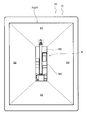
- FIG. 5 and 6 show a state in which only the overhead image P is displayed on the display unit 13 for easy understanding of the overhead image P, the operation unit 14 is also displayed on the display unit 13. And may not necessarily match the actual mode.
- the overhead image system 10 according to the present embodiment will be described with reference to FIGS. 1 to 8.
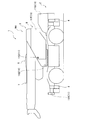
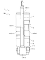
- the overhead view image system 10 is mounted on a crane vehicle 1 as an example of a work vehicle as shown in FIGS. 1 and 2.
- the crane vehicle 1 includes a traveling body (carrier) 2 and a swivel base 3.
- the traveling body 2 is a main body portion (vehicle body) of a vehicle having a traveling function.
- the traveling body 2 includes a plurality of wheels and a drive source that drives the wheels and the swivel base 3.
- the traveling body 2 has a substantially rectangular shape that is long in the front-rear direction (in FIG. 2, the vertical direction and the upper side is the front side of the traveling body 2) in plan view.
- the traveling body 2 is configured to allow the front side (upper side in FIG. 2) to travel in the vehicle traveling direction, retreat to the rear side (lower side in FIG. 2), and turn left and right by steering. Has been.
- the traveling body 2 is provided with a pair of left and right outriggers 4 (see FIG. 1 (only the left side of the traveling body 2 is shown in FIG. 1)) on the front side and the rear side.
- Each outrigger 4 is configured to be able to extend and retract to the left and right, and by appropriately extending and grounding, the traveling body 2 is stably supported during work using a boom 7 described later (operation mode Mw described later).
- the swivel base 3 is provided on the upper part of the traveling body 2 so as to be horizontally turnable.
- the swivel base 3 includes a cabin 5 and a boom support 6 that can swivel integrally.
- the cabin 5 is a place where an operator (operator) gets on, and the upper side in FIG. 2 is the front side of the cabin 5.
- the cabin 5 is provided with an operation unit for an operator to perform various operations.
- Various operations include, for example, turning of the swivel base 3, raising and lowering and expanding and contracting of a boom 7 described later, winding and lowering of a winch provided on the boom support 6, extension and storage of each outrigger 4, and starting of the engine And stop, traveling of the traveling body 2, and the like.
- the cabin 5 is provided on the right side of the turntable 3 with respect to the vehicle traveling direction (forward movement side).
- the swivel base 3 has such a size that the cabin 5 and the boom support 6 can be accommodated on the traveling body 2.
- the width of the cabin 5 (the dimension in the left-right direction in FIG. 2) is substantially equal to the traveling body 2, and the length dimension (the dimension in the vertical direction in FIG. 2) is smaller than that of the traveling body 2.
- the boom support 6 is a place where the boom 7 is attached.
- the base end of the boom 7 is attached to the boom support 6 via a boom root fulcrum pin.
- the boom 7 can be raised and lowered around the boom fulcrum pin.
- the boom support 6 is provided with a hoisting cylinder (not shown) between the boom support 6 and the boom 7.
- the boom 7 is raised and lowered by extending and retracting the raising and lowering cylinder.
- the boom 7 is arranged on the left side of the cabin 5 in the swivel 3 and extends in the front-rear direction. As shown in FIG. 1, the boom 7 is held in a horizontal posture when not in use such as traveling. The tip of the boom 7 (upper side in FIG. 2) protrudes forward from the traveling body 2.
- the boom 7 may be a so-called slant boom that is held in a posture in which the tip is lowered.
- the boom 7 has a proximal boom portion, an intermediate boom portion, and a distal boom portion that are connected to each other by an extension cylinder.
- the intermediate boom portion and the distal boom portion are accommodated in the base boom portion in a nested manner from the outside to the inside, and are expanded and contracted by extending and contracting the expansion cylinder.
- a sheave is provided at the distal end boom portion, and a wire is wound around the sheave to hang a hook.
- the boom 7 is in a state in which each boom portion is housed when not in use, such as during travel (a travel mode Md (see FIG. 2 or the like) described later).
- the crane vehicle 1 has a travel mode Md and a work mode Mw.
- the traveling mode Md the boom 7 is accommodated as described above, and the front side (vehicle traveling direction) of the traveling body 2 and the front side (front direction) of the cabin 5 (operator therein) in the swivel 3 are matched. In this state (see FIG. 2), this is a mode in which movement by traveling is performed.
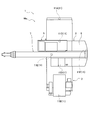
- the work mode Mw is a mode in which the traveling is stopped and the swivel base 3 can be swung with respect to the traveling body 2 to use the boom 7 as shown in FIG.
- the crane 1 is in the traveling mode Md when the shift switch is moved forward, neutral, or reverse.
- the crane 1 enters the work mode Mw when a PTO switch for driving a PTO (Power take-off), which is a mechanism for taking out the engine power for driving the vehicle to drive the work machine, is turned on.
- PTO Power take-off
- each outrigger 4 protrudes to the right and left as appropriate and is grounded, and the traveling body 2 is stably supported, so that the boom 3 is appropriately swung around the swivel base 3. 7 can be used.
- An overhead view image system 10 is mounted on the crane vehicle 1.
- the bird's-eye view image system 10 presents a bird's-eye view image P (see FIGS. 5 and 6) showing a state where the crane vehicle 1 is looked down from the upper (upper) virtual viewpoint in the vertical direction.
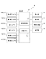
- the overhead image system 10 includes six cameras 11 (11A to 11F), a control unit 12, a display unit 13, an operation unit 14, an information acquisition unit 15, and a storage unit 16.
- Each camera 11 is provided at a predetermined position in view of acquiring an image around the traveling body 2 in the crane vehicle 1 and acquiring an image around the swivel 3 in the crane vehicle 1.
- the camera 11 for example, a wide-angle camera having an angle of view of approximately 180 degrees is used.
- the image of the periphery of the traveling body 2 is an image of the ground (the traveling surface) surrounding the traveling body 2 when viewed from the upper side (above) in the vertical direction, and the traveling body 2 is viewed from the periphery of the traveling body 2. It is an image of the ground in the area up to a predetermined distance from the center (see FIG. 5). Further, the image around the swivel base 3 is basically an image of the ground (traveling surface) surrounding the swivel base 3 when viewed from the upper side (upward) in the vertical direction. It is the image of the ground of the area
- the swivel base 3 is turnable above the traveling body 2, as will be described later, a part of the traveling body 2 may be reflected in an image around the swivel base 3 ( (See FIG. 6).
- the camera 11 has a first front camera 11 ⁇ / b> A that acquires a front image, a first rear camera 11 ⁇ / b> B that acquires a rear image, and a right image as a reference with the traveling body 2. It has a right camera 11C to acquire and a left camera 11D to acquire a left image.
- the first front camera 11A is provided at the end (front end) of the traveling body 2 on the forward side of the traveling body 2
- the first rear camera 11B is the end of the traveling body 2 on the backward side of the traveling body 2 ( It is provided at the rear end.
- the right camera 11 ⁇ / b> C is provided at the right end of the swivel base 3 on the right side of the cabin 5, and the left camera 11 ⁇ / b> D is provided at the left end of the swivel base 3 on the left side of the cabin 5.
- the traveling body 2 has a substantially rectangular shape that is long in the front-rear direction (vehicle traveling direction), even if a wide-angle camera is used, it is necessary to provide only one each on the left and right sides of the traveling body 2. It is difficult to acquire an image over the entire area.
- the crane 1 mounted with the bird's-eye view image system 10 has substantially the same width dimension between the traveling body 2 and the swivel base 3, the front side of the traveling body 2 and the front side of the swivel base 3 (cabin 5). In the traveling mode Md in which the two coincide with each other, both side ends of the turntable 3 substantially coincide with both side ends of the traveling body 2.
- the right camera 11C and the left camera 11D are provided on both sides of the turntable 3, and the installation positions thereof are more than those of the first front camera 11A and the first rear camera 11B provided on the traveling body 2. It is high. As a result, as compared with the case where cameras having the same performance are provided on both sides of the traveling body 2, the front and rear imaging areas are widened. Therefore, both sides of the turntable 3, that is, areas on both sides of the traveling body 2 in the traveling mode Md The images of the right area A3 and the left area A4 (see FIG. 5) can be acquired over the entire area.
- the bird's-eye view image system 10 includes the images of both sides of the traveling body 2 acquired by the right camera 11C and the left camera 11D and the traveling body acquired by the first front camera 11A and the first rear camera 11B in the traveling mode Md. Based on the two front and rear images, a bird's-eye view image P in which the periphery of the traveling body 2 can be viewed over the entire circumference can be generated (see FIG. 5).
- the camera 11 includes a second front camera 11E that acquires a front image and a second rear camera 11F that acquires a rear image with the swivel base 3 as a reference.
- the second front camera 11E is provided at the front end of the swivel base 3 on the front side of the cabin 5, and the second rear camera 11F is provided at the rear end of the swivel base 3 on the back side of the cabin 5.
- the bird's-eye view image system 10 includes images on both sides of the swivel base 3 acquired by the right camera 11C and the left camera 11D, and front and rear sides of the swivel base 3 acquired by the second front camera 11E and the second rear camera 11F.
- control unit 12 is connected to six cameras 11, a display unit 13, an operation unit 14, an information acquisition unit 15, and a storage unit 16.
- the control unit 12 is a microcomputer having a storage unit (internal memory 12a) and a calculation unit.
- the control unit 12 is provided in the cabin 5.
- the control unit 12 controls the operations of the camera 11, the display unit 13, the operation unit 14, the information acquisition unit 15, and the storage unit 16 based on a program stored in the storage unit 16 or the internal memory 12a. Information is appropriately acquired from the operation unit 14 and the information acquisition unit 15.
- the control unit 12 has been performed by the operation unit 14, the generation process of the overhead image P (its image data) based on the signal (image data) from the camera 11, the display process for displaying the overhead image P on the display unit 13, and the operation unit 14. Control of operation determination processing, acquisition processing of various information acquired by the information acquisition unit 15, and the like are performed.
- the control unit 12 generates an overhead image P (image data) from an image (image data) acquired by the camera 11 based on a program stored in the storage unit 16 or the internal memory 12a. 17.
- the image processing unit 17 performs a generation process for generating an overhead image P (image data) by performing the following processes. Note that this generation processing is performed even when a bird's-eye view image Pd (see FIG. 5), which will be described later, is used, except for the difference in the type (11A to 11F) of the camera 11 to be used, the coefficients used, and the like. Since the same applies to the case of (see), it is simply described as an overhead image P.
- the image processing unit 17 performs distortion correction processing for correcting distortion due to the lens by multiplying the coordinate value of the input pixel by a coefficient based on a lens distortion coefficient, an aspect ratio, or the like, and converting it to a coordinate value of the output pixel. Further, the image processing unit 17 sets all the coordinate values of the output pixels by multiplying the coordinate values of the appropriately selected input pixels by various coefficients based on the camera mounting angle and the like, and is set above the crane vehicle 1. An overhead conversion process is performed to convert the captured image (individual overhead image) as viewed from the virtual viewpoint.
- the image processing unit 17 eliminates the sense of discomfort at the joints by performing linear interpolation on the brightness of the corresponding coordinate values, and the adjacent captured images from the cameras 11 that have performed the above-described processes as one image.
- An image composition process for generating the overhead image P by connecting the images is performed.
- the image processing unit 17 switches the camera to be used according to the mode (travel mode Md or work mode Mw) in the crane vehicle 1 and generates the overhead image P.
- the image processing unit 17 images the first front camera 11A, the first rear camera 11B, the right camera 11C, and the left side.
- a traveling bird's-eye view image Pd (see FIG. 5) as the bird's-eye view image P is generated by the above-described processes using the image of the camera 11D. Since the first front camera 11A, the first rear camera 11B, the right camera 11C, and the left camera 11D are arranged in the positional relationship described above, the traveling overhead image Pd is a traveling body as shown in FIG.
- the periphery of 2 is an image continuously projected over the entire circumference.
- the traveling bird's-eye view image Pd includes an image (front image) of the front area A1 in front (forward side) of the traveling body 2 acquired by the first front camera 11A and a rear (reverse) of the traveling body 2 acquired by the first rear camera 11B.
- the image processing unit 17 includes an image of the second front camera 11E, an image of the second rear camera 11F, an image of the right camera 11C, and an image of the left camera 11D.
- a work overhead image Pw (see FIG. 6) as the overhead image P is generated by the above-described processes. Since the second front camera 11E, the second rear camera 11F, the right camera 11C, and the left camera 11D are arranged in the above-described positional relationship, the work overhead image Pw is, as shown in FIG.
- the periphery of 3 is an image continuously projected over the entire circumference.
- the work overhead image Pw includes an image (front image) of the front area A5 in front (front side) of the swivel 3 acquired by the second front camera 11E and a rear (rear surface) of the swivel 3 acquired by the second rear camera 11F.
- the traveling body 2 is partially reflected in the work overhead image Pw.
- the work overhead image Pw shows the traveling body 2 at a position corresponding to the degree of turning of the turntable 3. That is, in the work overhead image Pw, the traveling body 2 is displayed as a part of the peripheral image so as to rotate in the direction opposite to the turning direction of the turntable 3.
- the bird's-eye view images Pd and Pw synthesized in this way become images outside the installation position of the camera 11 in the crane 1 and are inward of the installation position. Image information of the area is missing. That is, the traveling bird's-eye view image Pd becomes an image outside the traveling body 2, and image information of a region where the traveling body 2 exists is missing. The work bird's-eye view image Pw becomes an image outside the swivel base 3, and image information of an area where the swivel base 3 exists is missing. For this reason, the image processing unit 17 sets a missing portion in each of the overhead images Pd and Pw to, for example, a pixel value of zero (black display).
- the image processing unit 17 superimposes a work vehicle sign M (see FIGS. 5 and 6) superimposed on the missing portion of the overhead images Pd and Pw that have been combined to represent the crane vehicle 1 in a simulated manner.
- the work vehicle sign M visualizes and indicates the position and size of the crane vehicle 1 in each overhead view image Pd, Pw. It has a sign part M2 and a swivel sign part M3 showing the swivel 3 including the boom 7 and the like thereon.
- the work vehicle sign M an overhead view photograph of the actual crane vehicle 1 may be used, or a design showing the crane vehicle 1 in an overhead view may be used.
- the image processing unit 17 switches the superimposed work vehicle sign M according to the mode (travel mode Md or work mode Mw) in the crane vehicle 1, that is, the generated overhead image P. Specifically, when the traveling bird's-eye view image Pd is generated in the traveling mode Md, the image processing unit 17 places the traveling body 2 on the traveling body marking unit M2 in the missing region where the traveling body 2 exists, as shown in FIG. The work vehicle sign M on which the swivel sign part M3 is overlapped is superimposed. In the work vehicle sign M at this time, similarly to the crane vehicle 1 (see FIG.
- the image processing unit 17 performs the work performed only from the turntable marker M3 in the missing region where the turntable 3 exists, as shown in FIG. A vehicle sign M is superimposed.
- This is an image of the work bird's-eye view image Pw covering the entire circumference of the periphery of the swivel base 3, and as described above, the traveling body 2 is reflected in the work bird's-eye view image Pw. This is because the swivel base mark portion M3 exists on the traveling body 2 as in the case of the crane vehicle 1.
- the control unit 12 outputs the overhead images Pd and Pw (image data) generated by the image processing unit 17 to the display unit 13 and displays them on the display unit 13 (see FIGS. 5 and 6).
- the images Pd and Pw are stored in the storage unit 16 as appropriate.
- the control unit 12 displays the front side of the traveling body marking unit M2 and the front side of the turntable marking unit M3, and the front areas A1 and A5 in the overhead images Pd and Pw, as viewed from the front of the display unit 13.
- Each of the overhead images Pd and Pw is displayed on the display unit 13.
- the control unit 12 performs a predetermined process based on operation information (data) from the operation unit 14 and various information (data) from the information acquisition unit 15.
- the display unit 13 can display a bird's-eye view image P and various types of information in the crane vehicle 1, and is provided in the cabin 5 of the swivel base 3 in the present embodiment.
- the display unit 13 can display the overhead image P (see FIGS. 5 and 6) generated based on the image acquired by the camera 11 immediately and continuously (in real time) under the control of the control unit 12.
- the display unit 13 has a touch panel function.
- the operation unit 14 is an operation unit for using various functions in the bird's-eye view image system 10, and outputs input information to the control unit 12.
- the operation unit 14 is configured as a screen (such as various icons therein) displayed on the display unit 13 having a touch panel function.
- the operation unit 14 can perform an operation for switching an image to be displayed on the display unit 13, an operation for various settings in the overhead image system 10 and the crane vehicle 1, and the like.
- the operation unit 14 may be provided in the cabin 5 independently of the display unit 13 or may be provided as a switch around the screen of the display unit 13.
- the information acquisition unit 15 acquires various types of operation information regarding the crane 1 and outputs each type of operation information (data) to the control unit 12.
- the operation information includes, for example, mode information indicating whether the crane vehicle 1 is in the traveling mode Md or the work mode Mw, the turning angle of the swivel 3 (boom 7), and the undulation angle and length of the boom 7.
- the attitude information shown is included.
- the information acquisition unit 15 acquires (detects) whether or not the shift switch of the crane vehicle 1 is set to forward, neutral, and reverse as mode information indicating the traveling mode Md. It is acquired (detected) whether or not the PTO switch of the crane 1 is turned on as mode information indicating Mw.
- 11C and the left camera 11D images around the traveling body 2 are acquired separately in front, rear, left, and right, and output to the control unit 12 (image processing unit 17).
- the image processing unit 17 performs each process on the image (image data) acquired by the camera 11 to generate the traveling bird's-eye view image Pd (overhead image P), and the swivel sign on the traveling body marker M2.
- the work vehicle sign M on which the part M3 is superimposed is superimposed on the traveling bird's-eye view image Pd.
- the traveling bird's-eye view image Pd on which the work vehicle sign M is superimposed is displayed on the display unit 13 under the control of the control unit 12 (see FIG. 5). Thereby, the worker can easily visually recognize the periphery of the traveling body 2 in the traveling mode Md of the crane vehicle 1.
- the overhead image system 10 uses the second front camera 11E, the second rear camera 11F, the right camera 11C, and the left camera 11D provided on the turntable 3 when the crane 1 is in the work mode Mw.
- images around the swivel base 3 are acquired separately in front, rear, left, and right, and output to the control unit 12 (image processing unit 17).
- the image processing unit 17 performs each process on the image (image data) acquired by the camera 11 to generate the work overhead image Pw (overhead image P), and the work performed only from the turntable marker M3.
- the vehicle sign M is superimposed on the work overhead image Pw.
- the work overhead image Pw on which the work vehicle sign M is superimposed is displayed on the display unit 13 under the control of the control unit 12 (see FIG. 6). Thereby, the worker can easily visually recognize the periphery of the swivel base 3 in the work mode Mw of the crane vehicle 1.
- the bird's-eye view image system 10 uses the right camera 11C and the left camera 11D provided on the swivel 3 in common regardless of the mode of the crane vehicle 1, and travels according to the mode of the crane vehicle 1.
- the first front camera 11A and the first rear camera 11B provided on the body 2 and the second front camera 11E and the second rear camera 11F provided on the swivel 3 are properly used. That is, the bird's-eye view image system 10 includes the first images acquired by the right camera 11C and the left camera 11D provided on the left and right of the swivel 3 and the first front camera 11A and the first image provided before and after the traveling body 2.
- the second image acquired by the second front camera 11E and the second rear camera 11F provided before and after the rear camera 11B or the swivel base 2 is acquired, and the first image and the second image are combined to form an overhead image.
- An image processing unit 17 to be generated is provided, and the camera that acquires the second image is switched according to the state of the crane vehicle 1 (work vehicle). Thereby, the bird's-eye view image P (running bird's-eye view image Pd, work bird's-eye view image Pw) adapted to the mode can be presented.
- FIG. 7 is a flowchart showing an overhead image display process (overhead image display method) executed by the control unit 12. This overhead image display process is executed by the control unit 12 based on a program stored in the internal memory 12 a or the storage unit 16 of the control unit 12.
- the flowchart in FIG. 7 is started when the overhead image system 10 is in a state of executing the overhead image display process.
- the bird's-eye view image system 10 may always be in a state of executing the bird's-eye view image display process, and may be able to switch whether or not to perform the operation by operating the operation unit 14.
- step S1 the control unit 12 determines whether or not the crane vehicle 1 is in the travel mode Md. If YES, the process proceeds to step S2, and if NO, the process proceeds to step S7.
- step S1 the control unit 12 acquires mode information via the information acquisition unit 15, and determines whether the crane 1 is in the travel mode Md or the work mode Mw based on the acquired mode information. . For example, the control unit 12 determines that the travel mode is Md when the shift switch of the crane 1 is in the forward, neutral, and reverse directions, and the operation is performed when the PTO switch of the crane 1 is in the ON state. It is determined that the mode is Mw.
- step S2 the control unit 12 acquires an image (image data) from the camera 11 corresponding to the travel mode Md, and proceeds to step S3.
- step S2 the control unit 12 displays each image (image data) from the camera 11 corresponding to the travel mode Md, that is, the first front camera 11A, the first rear camera 11B, the right camera 11C, and the left camera 11D. get.
- step S3 the control unit 12 generates a travel overhead image Pd (image data) and proceeds to step S4 (processing as the image processing unit 17).
- step S ⁇ b> 3 a traveling bird's-eye view image Pd (image data) that shows the periphery of the traveling member 2 and lacks image information in a region where the traveling member 2 exists is generated as the bird's-eye view image P.
- step S4 the control unit 12 superimposes the work vehicle sign M corresponding to the travel mode Md on the travel overhead image Pd, and proceeds to step S5 (processing as the image processing unit 17).
- step S4 an image is generated in which the work vehicle sign M corresponding to the travel mode Md, that is, the work vehicle sign M in which the turntable sign part M3 is superimposed on the traveling object sign part M2 is superimposed on the travel overhead image Pd.
- step S5 the control unit 12 causes the display unit 13 to display an image in which the work vehicle sign M corresponding to the travel mode Md is superimposed on the travel overhead image Pd (see FIG. 5), and then proceeds to step S6.
- step S6 the control unit 12 determines whether or not the travel mode Md has ended. If YES, the process proceeds to step S12. If NO, the process returns to step S2.
- step S6 the control part 12 acquires mode information via the information acquisition part 15, and judges whether the crane vehicle 1 complete
- step S7 the control unit 12 acquires an image (image data) from the camera 11 corresponding to the work mode Mw, and proceeds to step S8.
- step S7 since the control unit 12 is not in the travel mode Md, that is, the work mode Mw, the camera 11 corresponding to the work mode Mw, that is, the second front camera 11E, the second rear camera 11F, the right camera 11C, And each image (image data) from the left camera 11D is acquired.
- step S8 the control unit 12 generates a work overhead image Pw (image data) and proceeds to step S9 (processing as the image processing unit 17).
- step S ⁇ b> 8 a work overhead image Pw (image data) that shows the periphery of the swivel base 3 and lacks image information in a region where the swivel base 3 exists is generated as the overhead view image P.
- step S9 the control unit 12 superimposes the work vehicle sign M corresponding to the work mode Mw on the work overhead image Pw, and proceeds to step S10 (processing as the image processing unit 17).
- step S9 an image is generated by superimposing the work vehicle sign M corresponding to the work mode Mw, that is, the work vehicle sign M made only from the turntable mark unit M3, on the work overhead image Pw.
- step S10 the control unit 12 causes the display unit 13 to display an image in which the work vehicle sign M corresponding to the work mode Mw is superimposed on the work overhead image Pw (see FIG. 6), and proceeds to step S11.
- step S11 the control unit 12 determines whether or not the work mode Mw has ended following displaying the work overhead image Pw in step S10 on the display unit 13. If YES, the process proceeds to step S12. If NO, the process returns to step S7.
- step S11 the control part 12 acquires mode information via the information acquisition part 15, and judges whether the crane vehicle 1 complete
- step S12 the control unit 12 determines whether or not to end the overhead image display process. If YES, the overhead image display process is terminated. If NO, the process returns to step S1. In step S12, since the control unit 12 is a scene in which the continued mode (travel mode Md, work mode Mw) is ended, it is determined whether or not the control unit 12 ends the overhead image display processing, that is, on the display unit 13. It is determined whether or not to stop the display of the overhead image P. This determination may be performed based on, for example, the operation of the operation unit 14 or may be performed based on whether the overhead image system 10 is turned off or the crane vehicle 1 is stopped.
- step S2 to S6 determines whether or not to end the bird's-eye view image display process is determined while the travel mode Md is continued (steps S2 to S6) or while the work mode Mw is continued (steps S7 to S11). By doing so, display of the overhead image P can be stopped regardless of the mode of the crane vehicle 1.
- step S1 When the overhead view image system 10 is in a state of executing the overhead view image display process and the crane 1 is in the travel mode Md, the process proceeds from step S1 to step S3 to step S3 in the flowchart of FIG.
- the control unit 12 image processing unit 17
- step S4 by proceeding to step S4 in the flowchart of FIG. 7, the work vehicle sign M in which the swivel sign part M3 is superimposed on the traveling object sign part M2 is superimposed on the travel overhead image Pd, and the process proceeds to step S5.
- step S1 when the overhead view image system 10 is in a state of executing the overhead view image display process and the crane 1 is in the work mode Mw, the process proceeds from step S1 to step S7 to step S8 in the flowchart of FIG.
- the control unit 12 image processing unit 17
- step S9 the work vehicle sign M made only from the turntable sign unit M3
- step S10 the work vehicle sign M is displayed.
- An image superimposed on the work overhead image Pw is displayed on the display unit 13 (see FIG. 6).
- the overhead image system 10 continues the above process until it is determined in step S12 in the flowchart of FIG. 7 that the overhead image display process is terminated.
- the bird's-eye view image system 10 presents the surrounding bird's-eye view image P according to the mode of the crane 1 to the worker via the display unit 13 in real time.
- the bird's-eye view image system 10 changes the mode of the work vehicle sign M superimposed on the bird's-eye view image P according to the mode of the crane vehicle 1, the bird's-eye view image P is in a state close to the state where the actual crane vehicle 1 is seen from above. Is presented to the operator.
- the overhead image system 10 can obtain the following functions and effects.
- the overhead image system 10 is acquired by the first front camera 11A and the first rear camera 11B provided on the traveling body 2, and the right camera 11C and the left camera 11D provided on the turntable 3, respectively.
- a traveling bird's-eye view image Pd (bird's-eye view image P) that is an image around the traveling body 2 is generated using the obtained image. That is, the bird's-eye view image system 10 includes a plurality of cameras 11 that acquire peripheral images of the crane vehicle 1 (work vehicle) provided with the swivel 3 that can turn on the traveling body 2, and images acquired by the plurality of cameras 11.
- a display unit 13 that displays a bird's-eye view image P based thereon, and a control unit 12 that generates the bird's-eye view image P and displays the image on the display unit 13.
- a first front camera 11A that acquires an image
- a first rear camera 11B that is provided on the traveling body 2 and that acquires a rear image of the traveling body 2
- a right that is provided on the swivel base 3 and acquires a right image of the swivel base 3
- a left camera 11D that is provided on the swivel base 3 and acquires a left image of the swivel base 3.
- the overhead view image system 10 can make the installation positions of the right camera 11C and the left camera 11D higher than the first front camera 11A and the first rear camera 11B, and the traveling body 2 can move forward and backward (vehicle traveling direction). ), The images of the regions on both sides of the traveling body 2 can be acquired by one camera, respectively.
- the bird's-eye view image system 10 uses the images from the four cameras 11 (the first front camera 11A, the first rear camera 11B, the right camera 11C, and the left camera 11D), thereby moving back and forth (vehicle traveling direction).
- the overhead image system 10 uses the images acquired by the second front camera 11E, the second rear camera 11F, the right camera 11C, and the left camera 11D provided on the swivel 3 in the work mode Mw.
- a work overhead image Pw (overhead image P), which is an image around 3, is generated.
- the bird's-eye view image system 10 can always acquire the images of the front side, back side, and both sides of the swivel base 3 in the same combination regardless of the turning posture of the swivel base 3 with respect to the traveling body 2.
- the bird's-eye view image system 10 uses the images from the four cameras 11 (the second front camera 11E, the second rear camera 11F, the right camera 11C, and the left camera 11D), so that the traveling body 2 can be used.
- a work overhead image Pw that is an image over the entire circumference of the swivel 3 to be swiveled can be appropriately generated and presented to the operator.
- the bird's-eye view image system 10 uses the right camera 11C and the left camera 11D provided on the swivel 3 in common regardless of the mode of the crane vehicle 1, and the traveling body 2 according to the mode of the crane vehicle 1.
- the first front camera 11 ⁇ / b> A and the first rear camera 11 ⁇ / b> B provided in FIG. 5 and the second front camera 11 ⁇ / b> E and the second rear camera 11 ⁇ / b> F provided on the swivel 3 are properly used.
- the plurality of cameras 11 acquire the rear image of the swivel base 3 provided on the swivel 3 and the second front camera 11 ⁇ / b> E that is provided on the swivel 3 and acquires the front image of the swivel 3.
- the control unit 12 in the traveling mode Md, the image of the first front camera 11A, the image of the first rear camera 11B, the image of the right camera 11C, and the left camera 11D.
- a traveling bird's-eye view image Pd (bird's-eye view image) is generated on the basis of the images of the images, and in the work mode Mw, the image of the second front camera 11E, the image of the second rear camera 11F, the image of the right camera 11C, and the left camera 11D.
- the work overhead view image Pw (overhead view image) is generated based on the image. Therefore, the overhead image system 10 can appropriately generate the traveling overhead image Pd around the traveling body 2 and the work overhead image Pw around the swivel 3 while suppressing an increase in the number of cameras to be used.
- the bird's-eye view image system 10 includes both the driving bird's-eye view image Pd and the work bird's-eye view image Pw by simply switching between the first front camera 11A and the first rear camera 11B, and the second front camera 11E and the second rear camera 11F. Therefore, the traveling overhead image Pd and the work overhead image Pw can be appropriately generated with a simple configuration.
- the bird's-eye view image system 10 superimposes the work vehicle sign M in which the swivel sign part M3 is superimposed on the traveling object sign part M2 on the traveling bird's-eye view image Pd, and the work bird's-eye view image Pw includes only the swivel sign part M3.
- a work vehicle sign M is superimposed. That is, in the bird's-eye view image system 10, in the traveling mode Md, the control unit 12 replaces the traveling body marking unit M2 indicating the traveling body 2 and the turning platform marking unit M3 indicating the swivel 3 with the crane vehicle 1 (work vehicle).
- the work vehicle sign M that is visualized is superimposed on the traveling bird's-eye view image Pd (bird's-eye view image) and displayed on the display unit 13.
- the traveling bird's-eye view image Pd bird's-eye view image
- the traveling overhead image Pd is an image that covers the entire periphery of the traveling vehicle 2.
- the crane vehicle 1 does not move in the work mode Mw, and the swivel base 3 that is swung thereon moves, so that the work overhead image Pw covers the entire periphery of the swivel base 3.
- An image is desirable.
- the second front camera 11E, the second rear camera 11F, the right camera 11C, and the left camera 11D used for the work overhead image Pw are images of the traveling body 2 according to the turning posture of the turntable 3 with respect to the traveling body 2.
- the bird's-eye view image system 10 can generate each bird's-eye view image P required by the worker according to the mode of the crane vehicle 1, and the actual crane while superimposing the work vehicle sign M superimposed thereon on the mode.
- the vehicle 1 can be close to the bird's-eye view.
- the traveling mode Md is superimposed by superimposing the work vehicle sign M with the turntable sign part M3 superimposed on the traveling object sign part M2.
- the overhead view image system 10 displays the periphery of the turntable 3 together with the traveling body 2 in the work overhead view image Pw, by superimposing the work vehicle sign M made only from the turntable mark portion M3, According to the turning posture, the traveling body 2 on the work overhead image Pw turns in the reverse direction with respect to the turntable marking unit M3, and the surroundings of the actual crane vehicle 1 in the work mode Mw are looked down around the turntable 3 as a center. Can be close to For this reason, the bird's-eye view image system 10 can present the bird's-eye view image P that allows the operator to easily and appropriately grasp the surrounding situation without feeling uncomfortable.
- the bird's-eye view image system 10 directs the work vehicle sign M superimposed on the traveling bird's-eye view image Pd to the upper side of the display unit 13 with the front side of the traveling body sign unit M2 and the front side of the swivel mark unit M3 being aligned ( (See FIG. 5). For this reason, the bird's-eye view image system 10 can make the driving bird's-eye view image Pd (see FIG. 5) presented in the driving mode Md closer to the feeling seen by the worker in the cabin 5, and the swivel base sign portion M3. Can be configured in the same manner as the crane vehicle 1 (see FIG. 2) traveling in the traveling mode Md. Thereby, the bird's-eye view image system 10 can make it easier to visually recognize the periphery of the traveling body 2 in the traveling mode Md.
- the bird's-eye view image system 10 has the work vehicle sign M to be superimposed on the work bird's-eye view image Pw facing the front side of the turntable sign unit M3 on the upper side of the display unit 13 (see FIG. 6). For this reason, the bird's-eye view image system 10 can make the work bird's-eye view image Pw (see FIG. 6) presented in the work mode Mw closer to the sensation seen by the worker in the cabin 5, and the swivel marker part M 3. Can be configured in the same manner as the crane vehicle 1 (see FIG. 3) that is driven in the work mode Mw. Thereby, the bird's-eye view image system 10 can make the periphery of the turntable 3 visible more easily in the work mode Mw.
- the periphery of the traveling body 2 provided with the swivel base 3 having the cabin 5 can be made visible over the entire circumference.
- the overhead image system of the present invention has been described based on the embodiment.
- the specific configuration is not limited to the embodiment, and design changes, additions, and the like are possible without departing from the gist of the present invention. Is acceptable.
- the number, position, shape, and the like of the constituent members are not limited to the examples, and the number, position, shape, and the like that are suitable for implementing the present invention can be used.
- the bird's-eye view image system 10 as an example of the bird's-eye view image system according to the present invention has been described.
- a peripheral image of a work vehicle provided with a turntable capable of turning on the traveling body is acquired.
- a control unit that generates and displays the display unit on the display unit, wherein each camera is provided on the traveling body on the forward side of the traveling body and on the traveling body on the backward side of the traveling body.
- a rear camera provided; a right camera provided on the swivel on the right side of the cabin provided on the swivel; and a left camera provided on the swivel on the left side of the cabin.
- a left camera in may be a configured top view image system is not limited to the above embodiment.
- the crane vehicle 1 was shown as a work vehicle using the bird's-eye view image system 10 in the above-described embodiment, if the work vehicle is provided with a turntable (3) capable of turning on the traveling body (2), A work vehicle having another configuration may be used, and is not limited to the above-described embodiment.
- the work vehicle sign M is superimposed on each overhead view image Pd, Pw as shown in FIG. 5 or FIG.
- the overhead images Pd and Pw are partially hidden.
- the tip portion of the boom 7 surrounded by a dotted line corresponds to the place where the bird's-eye view images Pd and Pw are hidden.
- the work bird's-eye view image Pw shown in FIG. 6 a part of the cabin 5 surrounded by a dotted line and about half of the tip side of the boom 7 correspond.
- These hidden locations are locations located outside the traveling body 2 in the swivel base 3 in the traveling bird's-eye view image Pd when the crane vehicle 1 is viewed from above in the vertical direction.
- the front is a position positioned in front of the second front camera 11E in the swivel 3 and the rear and both sides are positions outside the swivel 3.
- the inside of these hidden portions is indicated by lines while the inside is made transparent or semi-transparent, or non-transparent
- the displayed work vehicle sign M may be superimposed on each overhead view image Pd, Pw. This can be executed by processing the display of the hidden part in each overhead view image Pd, Pw and work vehicle sign M.
- the work overhead image Pw is displayed on the display unit 13 in the work mode Mw, but other images may be displayed, and the present invention is not limited to the embodiment.
- a front through image Ps that displays an image acquired by the second front camera 11E without any processing is included.
- the traveling body 2 since the front through image Ps in a state where the swivel base 3 is turned with respect to the traveling body 2 as shown in FIG. 3, the traveling body 2 is not shown in the front through image Ps. However, depending on the rotation posture of the swivel base 3, the traveling body 2 is partially captured.
- the display of the front through image Ps can be switched to the work overhead image Pw to improve usability. Further, both the work overhead image Pw and the front through image Ps may be simultaneously displayed on the display unit 13. Furthermore, the display unit 13 displays (can be switched or simultaneously displayed) as other images, through images acquired by other cameras (11A to 11D, 11F) and images based on the respective cameras (11A to 11F). 8), and is not limited to the example of FIG. The same applies to the traveling mode Md.
Landscapes
- Engineering & Computer Science (AREA)
- Mechanical Engineering (AREA)
- Multimedia (AREA)
- Signal Processing (AREA)
- Mining & Mineral Resources (AREA)
- Civil Engineering (AREA)
- General Engineering & Computer Science (AREA)
- Structural Engineering (AREA)
- Physics & Mathematics (AREA)
- General Physics & Mathematics (AREA)
- Theoretical Computer Science (AREA)
- Automation & Control Theory (AREA)
- Closed-Circuit Television Systems (AREA)
- Component Parts Of Construction Machinery (AREA)
- Fittings On The Vehicle Exterior For Carrying Loads, And Devices For Holding Or Mounting Articles (AREA)
- Jib Cranes (AREA)
- Image Processing (AREA)
- Image Analysis (AREA)
Abstract
L'invention concerne un système d'image de vue à vol d'oiseau, un véhicule de travail, un procédé d'affichage d'image de vue à vol d'oiseau, et un programme avec lequel il est possible de restituer l'environnement d'un corps mobile pourvu d'une base pivotante ayant une cabine visible sur toute la circonférence. Le système d'image de vue à vol d'oiseau est pourvu d'une pluralité de caméras pour acquérir une image environnante du véhicule de travail, une unité d'affichage pour afficher une image de vue à vol d'oiseau sur la base de l'image acquise par la pluralité de caméras, et une unité de commande pour amener une image de vue à vol d'oiseau à être générée et affichée par l'unité d'affichage. La pluralité de caméras comprend une première caméra vers l'avant disposée dans le corps mobile pour acquérir une image en avant du corps mobile, une première caméra arrière disposée dans le corps mobile pour acquérir une image vers l'arrière du corps mobile, une caméra droite disposée sur la base pivotante pour acquérir une image vers la droite de la base pivotante, et une caméra gauche disposée sur la base pivotante pour acquérir une image vers la gauche de la base pivotante.
Priority Applications (3)
| Application Number | Priority Date | Filing Date | Title |
|---|---|---|---|
| EP17848892.0A EP3512194B1 (fr) | 2016-09-09 | 2017-09-08 | Système d'image de vue à vol d'oiseau, procédé d'affichage d'image de vue à vol d'oiseau et programme |
| US16/329,420 US10661712B2 (en) | 2016-09-09 | 2017-09-08 | Bird's-eye view image system, bird's-eye view image display method and program |
| CN201780053672.0A CN109661813B (zh) | 2016-09-09 | 2017-09-08 | 俯瞰图像系统、俯瞰图像显示方法以及存储有程序的计算机可读取的记录介质 |
Applications Claiming Priority (2)
| Application Number | Priority Date | Filing Date | Title |
|---|---|---|---|
| JP2016-176872 | 2016-09-09 | ||
| JP2016176872A JP6756555B2 (ja) | 2016-09-09 | 2016-09-09 | 俯瞰画像システム、俯瞰画像表示方法およびプログラム |
Publications (1)
| Publication Number | Publication Date |
|---|---|
| WO2018047954A1 true WO2018047954A1 (fr) | 2018-03-15 |
Family
ID=61562325
Family Applications (1)
| Application Number | Title | Priority Date | Filing Date |
|---|---|---|---|
| PCT/JP2017/032534 Ceased WO2018047954A1 (fr) | 2016-09-09 | 2017-09-08 | Système d'image de vue à vol d'oiseau, procédé d'affichage d'image de vue à vol d'oiseau et programme |
Country Status (5)
| Country | Link |
|---|---|
| US (1) | US10661712B2 (fr) |
| EP (1) | EP3512194B1 (fr) |
| JP (1) | JP6756555B2 (fr) |
| CN (1) | CN109661813B (fr) |
| WO (1) | WO2018047954A1 (fr) |
Cited By (2)
| Publication number | Priority date | Publication date | Assignee | Title |
|---|---|---|---|---|
| JPWO2020218455A1 (fr) * | 2019-04-26 | 2020-10-29 | ||
| WO2020256101A1 (fr) * | 2019-06-20 | 2020-12-24 | 株式会社タダノ | Système d'image et engin de chantier pourvu du système d'image |
Families Citing this family (12)
| Publication number | Priority date | Publication date | Assignee | Title |
|---|---|---|---|---|
| KR102707140B1 (ko) * | 2017-12-27 | 2024-09-13 | 스미토모 겐키 가부시키가이샤 | 쇼벨 및 쇼벨의 출력장치 |
| JP6607272B2 (ja) * | 2018-03-02 | 2019-11-20 | 株式会社Jvcケンウッド | 車両用記録装置、車両用記録方法及びプログラム |
| JP7147248B2 (ja) | 2018-04-27 | 2022-10-05 | 株式会社タダノ | クレーン車 |
| JP7059956B2 (ja) * | 2019-02-08 | 2022-04-26 | コベルコ建機株式会社 | 建設機械の障害物検出装置 |
| JP7518664B2 (ja) * | 2020-05-27 | 2024-07-18 | 株式会社アイチコーポレーション | 作業車 |
| JP7620396B2 (ja) | 2020-05-27 | 2025-01-23 | 株式会社アイチコーポレーション | 作業車 |
| CN112019752A (zh) * | 2020-09-11 | 2020-12-01 | 三一汽车起重机械有限公司 | 一种全景监控方法、全景监控系统及起重机 |
| US12195306B2 (en) | 2021-04-12 | 2025-01-14 | Structural Services, Inc. | Systems and methods for identifying and locating building material objects |
| AU2022258326A1 (en) | 2021-04-12 | 2023-11-23 | Structural Services, Inc. | Systems and methods for assisting a crane operator |
| CN113225527A (zh) * | 2021-04-14 | 2021-08-06 | 三一海洋重工有限公司 | 一种全景视频监控方法、装置及一种工程设备 |
| JP2023082954A (ja) * | 2021-12-03 | 2023-06-15 | 本田技研工業株式会社 | 制御装置、制御方法、及び制御プログラム |
| US20240308830A1 (en) * | 2023-03-13 | 2024-09-19 | Oshkosh Corporation | Systems and methods for direction of travel |
Citations (7)
| Publication number | Priority date | Publication date | Assignee | Title |
|---|---|---|---|---|
| JP2010059653A (ja) * | 2008-09-02 | 2010-03-18 | Hitachi Constr Mach Co Ltd | 作業機械の視野補助装置 |
| JP2011151742A (ja) * | 2010-01-25 | 2011-08-04 | Tadano Ltd | 画像表示システム |
| JP2012107395A (ja) * | 2010-11-15 | 2012-06-07 | Sumitomo (Shi) Construction Machinery Co Ltd | 建設機械のモニター装置 |
| JP2013121056A (ja) * | 2011-12-07 | 2013-06-17 | Fujitsu Ten Ltd | 画像処理装置、車両、画像処理方法、及び、プログラム |
| JP2015139158A (ja) * | 2014-01-23 | 2015-07-30 | クラリオン株式会社 | 重機用周辺監視装置 |
| WO2015125979A1 (fr) * | 2015-04-28 | 2015-08-27 | 株式会社小松製作所 | Dispositif de surveillance du périmètre d'un engin de travail, et procédé de surveillance de périmètre d'un engin de travail |
| JP2016030891A (ja) * | 2014-07-25 | 2016-03-07 | 日立建機株式会社 | 旋回式作業機の周囲表示装置 |
Family Cites Families (5)
| Publication number | Priority date | Publication date | Assignee | Title |
|---|---|---|---|---|
| US7448812B2 (en) * | 2004-05-27 | 2008-11-11 | Heibel Thomas S | Camera mount |
| JP4934308B2 (ja) * | 2005-10-17 | 2012-05-16 | 三洋電機株式会社 | 運転支援システム |
| CN101442618A (zh) * | 2008-12-31 | 2009-05-27 | 葛晨阳 | 用于车辆辅助驾驶的360度环形视频合成方法 |
| CN102175222B (zh) * | 2011-03-04 | 2012-09-05 | 南开大学 | 基于立体视觉的吊车避障系统 |
| JP6313992B2 (ja) * | 2014-02-18 | 2018-04-18 | クラリオン株式会社 | 牽引車用周囲監視装置 |
-
2016
- 2016-09-09 JP JP2016176872A patent/JP6756555B2/ja active Active
-
2017
- 2017-09-08 US US16/329,420 patent/US10661712B2/en active Active
- 2017-09-08 CN CN201780053672.0A patent/CN109661813B/zh active Active
- 2017-09-08 WO PCT/JP2017/032534 patent/WO2018047954A1/fr not_active Ceased
- 2017-09-08 EP EP17848892.0A patent/EP3512194B1/fr active Active
Patent Citations (7)
| Publication number | Priority date | Publication date | Assignee | Title |
|---|---|---|---|---|
| JP2010059653A (ja) * | 2008-09-02 | 2010-03-18 | Hitachi Constr Mach Co Ltd | 作業機械の視野補助装置 |
| JP2011151742A (ja) * | 2010-01-25 | 2011-08-04 | Tadano Ltd | 画像表示システム |
| JP2012107395A (ja) * | 2010-11-15 | 2012-06-07 | Sumitomo (Shi) Construction Machinery Co Ltd | 建設機械のモニター装置 |
| JP2013121056A (ja) * | 2011-12-07 | 2013-06-17 | Fujitsu Ten Ltd | 画像処理装置、車両、画像処理方法、及び、プログラム |
| JP2015139158A (ja) * | 2014-01-23 | 2015-07-30 | クラリオン株式会社 | 重機用周辺監視装置 |
| JP2016030891A (ja) * | 2014-07-25 | 2016-03-07 | 日立建機株式会社 | 旋回式作業機の周囲表示装置 |
| WO2015125979A1 (fr) * | 2015-04-28 | 2015-08-27 | 株式会社小松製作所 | Dispositif de surveillance du périmètre d'un engin de travail, et procédé de surveillance de périmètre d'un engin de travail |
Cited By (8)
| Publication number | Priority date | Publication date | Assignee | Title |
|---|---|---|---|---|
| JPWO2020218455A1 (fr) * | 2019-04-26 | 2020-10-29 | ||
| WO2020218455A1 (fr) * | 2019-04-26 | 2020-10-29 | 住友建機株式会社 | Excavatrice |
| JP7407178B2 (ja) | 2019-04-26 | 2023-12-28 | 住友建機株式会社 | ショベル |
| US12252868B2 (en) | 2019-04-26 | 2025-03-18 | Sumitomo Construction Machinery Co., Ltd. | Shovel |
| WO2020256101A1 (fr) * | 2019-06-20 | 2020-12-24 | 株式会社タダノ | Système d'image et engin de chantier pourvu du système d'image |
| JPWO2020256101A1 (fr) * | 2019-06-20 | 2020-12-24 | ||
| EP3988491A4 (fr) * | 2019-06-20 | 2023-08-02 | Tadano Ltd. | Système d'image et engin de chantier pourvu du système d'image |
| US12187584B2 (en) | 2019-06-20 | 2025-01-07 | Tadano Ltd. | Image system and work vehicle provided with image system |
Also Published As
| Publication number | Publication date |
|---|---|
| CN109661813A (zh) | 2019-04-19 |
| EP3512194A4 (fr) | 2020-04-01 |
| EP3512194A1 (fr) | 2019-07-17 |
| JP6756555B2 (ja) | 2020-09-16 |
| US10661712B2 (en) | 2020-05-26 |
| CN109661813B (zh) | 2020-10-02 |
| US20190248289A1 (en) | 2019-08-15 |
| EP3512194B1 (fr) | 2021-04-21 |
| JP2018042207A (ja) | 2018-03-15 |
Similar Documents
| Publication | Publication Date | Title |
|---|---|---|
| WO2018047954A1 (fr) | Système d'image de vue à vol d'oiseau, procédé d'affichage d'image de vue à vol d'oiseau et programme | |
| JP5814187B2 (ja) | 自走式産業機械の表示装置 | |
| JP5462008B2 (ja) | 画像表示システム | |
| JP5068779B2 (ja) | 車両周囲俯瞰画像表示装置及び方法 | |
| JP6589468B2 (ja) | 移動式クレーンの周囲表示装置 | |
| JP5914013B2 (ja) | 運転支援装置 | |
| JP5775283B2 (ja) | 作業機械のモニタ装置 | |
| JP2012051678A (ja) | 視界補助システム | |
| JP6321977B2 (ja) | 重機用周辺監視装置 | |
| WO2013183536A1 (fr) | Dispositif d'affichage pour une machine industrielle automotrice | |
| JP2008312004A (ja) | カメラシステム及び機械装置 | |
| CN103797789A (zh) | 工作机械的周围监视装置 | |
| JP5251804B2 (ja) | 運転支援装置 | |
| JP2001163132A (ja) | 車両後方監視装置用画像変換装置 | |
| WO2013172172A1 (fr) | Dispositif d'affichage pour une machine industrielle autopropulsée | |
| JP5841821B2 (ja) | 画像処理装置、車両、画像処理方法、及び、プログラム | |
| JP5066198B2 (ja) | 作業機械のモニタ装置 | |
| JP5776995B2 (ja) | 車両用周辺監視装置 | |
| JP5996879B2 (ja) | 作業機械の周囲監視装置 | |
| JP6713884B2 (ja) | 俯瞰画像システム、俯瞰画像表示方法およびプログラム | |
| JP6139740B2 (ja) | 作業機械の周囲監視装置 | |
| JP6756554B2 (ja) | 画像表示システム | |
| JP2018039648A (ja) | 画像表示システム | |
| JP2018039477A (ja) | 画像表示システム | |
| JP2012001126A (ja) | 車両用周辺監視装置 |
Legal Events
| Date | Code | Title | Description |
|---|---|---|---|
| 121 | Ep: the epo has been informed by wipo that ep was designated in this application |
Ref document number: 17848892 Country of ref document: EP Kind code of ref document: A1 |
|
| NENP | Non-entry into the national phase |
Ref country code: DE |
|
| ENP | Entry into the national phase |
Ref document number: 2017848892 Country of ref document: EP Effective date: 20190409 |