WO2018066084A1 - Moteur et dispositif de climatisation - Google Patents
Moteur et dispositif de climatisation Download PDFInfo
- Publication number
- WO2018066084A1 WO2018066084A1 PCT/JP2016/079570 JP2016079570W WO2018066084A1 WO 2018066084 A1 WO2018066084 A1 WO 2018066084A1 JP 2016079570 W JP2016079570 W JP 2016079570W WO 2018066084 A1 WO2018066084 A1 WO 2018066084A1
- Authority
- WO
- WIPO (PCT)
- Prior art keywords
- permanent magnet
- tooth
- groove
- electric motor
- teeth
- Prior art date
- Legal status (The legal status is an assumption and is not a legal conclusion. Google has not performed a legal analysis and makes no representation as to the accuracy of the status listed.)
- Ceased
Links
Images




Classifications
-
- F—MECHANICAL ENGINEERING; LIGHTING; HEATING; WEAPONS; BLASTING
- F24—HEATING; RANGES; VENTILATING
- F24F—AIR-CONDITIONING; AIR-HUMIDIFICATION; VENTILATION; USE OF AIR CURRENTS FOR SCREENING
- F24F1/00—Room units for air-conditioning, e.g. separate or self-contained units or units receiving primary air from a central station
- F24F1/06—Separate outdoor units, e.g. outdoor unit to be linked to a separate room comprising a compressor and a heat exchanger
- F24F1/20—Electric components for separate outdoor units
-
- H—ELECTRICITY
- H02—GENERATION; CONVERSION OR DISTRIBUTION OF ELECTRIC POWER
- H02K—DYNAMO-ELECTRIC MACHINES
- H02K1/00—Details of the magnetic circuit
- H02K1/06—Details of the magnetic circuit characterised by the shape, form or construction
- H02K1/12—Stationary parts of the magnetic circuit
- H02K1/14—Stator cores with salient poles
- H02K1/146—Stator cores with salient poles consisting of a generally annular yoke with salient poles
-
- H—ELECTRICITY
- H02—GENERATION; CONVERSION OR DISTRIBUTION OF ELECTRIC POWER
- H02K—DYNAMO-ELECTRIC MACHINES
- H02K1/00—Details of the magnetic circuit
- H02K1/06—Details of the magnetic circuit characterised by the shape, form or construction
- H02K1/22—Rotating parts of the magnetic circuit
- H02K1/27—Rotor cores with permanent magnets
- H02K1/2706—Inner rotors
- H02K1/272—Inner rotors the magnetisation axis of the magnets being perpendicular to the rotor axis
- H02K1/274—Inner rotors the magnetisation axis of the magnets being perpendicular to the rotor axis the rotor consisting of two or more circumferentially positioned magnets
- H02K1/2753—Inner rotors the magnetisation axis of the magnets being perpendicular to the rotor axis the rotor consisting of two or more circumferentially positioned magnets the rotor consisting of magnets or groups of magnets arranged with alternating polarity
- H02K1/278—Surface mounted magnets; Inset magnets
-
- H—ELECTRICITY
- H02—GENERATION; CONVERSION OR DISTRIBUTION OF ELECTRIC POWER
- H02K—DYNAMO-ELECTRIC MACHINES
- H02K1/00—Details of the magnetic circuit
- H02K1/06—Details of the magnetic circuit characterised by the shape, form or construction
- H02K1/22—Rotating parts of the magnetic circuit
- H02K1/28—Means for mounting or fastening rotating magnetic parts on to, or to, the rotor structures
- H02K1/30—Means for mounting or fastening rotating magnetic parts on to, or to, the rotor structures using intermediate parts, e.g. spiders
-
- H—ELECTRICITY
- H02—GENERATION; CONVERSION OR DISTRIBUTION OF ELECTRIC POWER
- H02K—DYNAMO-ELECTRIC MACHINES
- H02K21/00—Synchronous motors having permanent magnets; Synchronous generators having permanent magnets
- H02K21/12—Synchronous motors having permanent magnets; Synchronous generators having permanent magnets with stationary armatures and rotating magnets
- H02K21/14—Synchronous motors having permanent magnets; Synchronous generators having permanent magnets with stationary armatures and rotating magnets with magnets rotating within the armatures
- H02K21/16—Synchronous motors having permanent magnets; Synchronous generators having permanent magnets with stationary armatures and rotating magnets with magnets rotating within the armatures having annular armature cores with salient poles
-
- F—MECHANICAL ENGINEERING; LIGHTING; HEATING; WEAPONS; BLASTING
- F24—HEATING; RANGES; VENTILATING
- F24F—AIR-CONDITIONING; AIR-HUMIDIFICATION; VENTILATION; USE OF AIR CURRENTS FOR SCREENING
- F24F1/00—Room units for air-conditioning, e.g. separate or self-contained units or units receiving primary air from a central station
- F24F1/06—Separate outdoor units, e.g. outdoor unit to be linked to a separate room comprising a compressor and a heat exchanger
- F24F1/26—Refrigerant piping
- F24F1/32—Refrigerant piping for connecting the separate outdoor units to indoor units
-
- F—MECHANICAL ENGINEERING; LIGHTING; HEATING; WEAPONS; BLASTING
- F24—HEATING; RANGES; VENTILATING
- F24F—AIR-CONDITIONING; AIR-HUMIDIFICATION; VENTILATION; USE OF AIR CURRENTS FOR SCREENING
- F24F1/00—Room units for air-conditioning, e.g. separate or self-contained units or units receiving primary air from a central station
- F24F1/06—Separate outdoor units, e.g. outdoor unit to be linked to a separate room comprising a compressor and a heat exchanger
- F24F1/38—Fan details of outdoor units, e.g. bell-mouth shaped inlets or fan mountings
-
- H—ELECTRICITY
- H02—GENERATION; CONVERSION OR DISTRIBUTION OF ELECTRIC POWER
- H02K—DYNAMO-ELECTRIC MACHINES
- H02K2201/00—Specific aspects not provided for in the other groups of this subclass relating to the magnetic circuits
- H02K2201/03—Machines characterised by aspects of the air-gap between rotor and stator
-
- H—ELECTRICITY
- H02—GENERATION; CONVERSION OR DISTRIBUTION OF ELECTRIC POWER
- H02K—DYNAMO-ELECTRIC MACHINES
- H02K2213/00—Specific aspects, not otherwise provided for and not covered by codes H02K2201/00 - H02K2211/00
- H02K2213/03—Machines characterised by numerical values, ranges, mathematical expressions or similar information
Definitions
- the present invention relates to an electric motor and an air conditioner using the electric motor.
- an electric motor called an SPM (Surface Permanent Magnet) motor in which a permanent magnet is attached to the surface of a rotor has been widely used.
- the permanent magnet has magnetic poles (N pole and S pole) alternately arranged in the circumferential direction of the rotor.
- a coil is wound around the stator, and the magnetic flux generated by the current flowing through the coil also flows on the surface of the permanent magnet. Due to the magnetic flux from the stator, demagnetization may occur at the portion between the adjacent magnetic poles of the permanent magnet.
- Patent Document 1 For the purpose of suppressing demagnetization, a structure in which a groove is formed in the interpole portion of a permanent magnet attached to a rotor has been proposed (see, for example, Patent Document 1).
- the present invention has been made to solve the above-described problems, and an object thereof is to effectively suppress demagnetization of a permanent magnet in an electric motor.
- An electric motor includes an annular yoke centering on an axis, a stator having first and second teeth extending from the yoke to the inner peripheral side or the outer peripheral side, and rotating about the axis
- a possible rotor comprising a rotor having a permanent magnet on a surface facing the stator.
- Each of the first tooth and the second tooth has a tip portion facing the permanent magnet.
- the permanent magnet has a first magnetic pole and a second magnetic pole that are adjacent to each other in the circumferential direction about the axis, and a groove that is formed between the first magnetic pole and the second magnetic pole.
- the circumferential interval L1 between the tip portion of the first tooth and the tip portion of the second tooth and the circumferential width L2 of the groove satisfy 1.00 ⁇ L2 / L1 ⁇ 3.75. .
- a groove is formed in the interpolar portion of the permanent magnet, and the distance L1 between the tip portion of the first tooth and the tip portion of the second tooth and the width L2 of the groove are 1.00 ⁇ L2 / L1 ⁇ With the configuration satisfying 3.75, a sufficient demagnetization suppressing effect can be obtained.
- FIG. 1 is a cross-sectional view illustrating a configuration of an electric motor according to a first embodiment.
- 2 is an enlarged cross-sectional view of a part of the electric motor according to Embodiment 1.
- FIG. 2 is a partial side cross-sectional view showing the configuration of the electric motor according to Embodiment 1.
- FIG. 1 is a cross-sectional view showing a configuration of a rotor of an electric motor according to Embodiment 1.
- FIG. It is a schematic diagram for demonstrating the magnetic flux which flows from a stator to a rotor. It is a graph which shows the relationship between L2 / L1 and a demagnetization proof stress improvement rate. It is a schematic diagram which shows the 1st example (A) and 2nd example (B) of groove shape.
- FIG. 6 is a cross-sectional view showing a configuration of a stator core according to a modification of the first embodiment. 6 is a schematic diagram illustrating a configuration of a permanent magnet according to Embodiment 2.
- FIG. 6 is a schematic diagram illustrating a configuration of a permanent magnet according to Embodiment 3.
- FIG. 6 is a schematic diagram illustrating a configuration of an electric motor according to a fourth embodiment.
- FIG. 10 is a schematic diagram illustrating a configuration of an electric motor according to a fifth embodiment. It is a mimetic diagram showing composition of an air harmony device to which an electric motor of each embodiment is applied. It is a schematic diagram which shows the structure of the outdoor unit of the air conditioning apparatus of FIG.
- FIG. 1 is a cross-sectional view showing electric motor 100 of the first embodiment.
- the electric motor 100 is an inner rotor type electric motor that includes an annular stator 1 and a rotor 4 that is rotatably provided on the inner peripheral side of the stator 1. Between the stator 1 and the rotor 4, for example, a gap 17 of 0.5 mm is provided.
- the rotor 4 holds a permanent magnet 5 on the surface (outer peripheral surface).
- the electric motor that holds the permanent magnet on the surface of the rotor in this way is called an SPM motor.
- the rotation center of the rotor 4 is referred to as an axis C1
- the direction of the axis C1 is referred to as an “axial direction”.
- a direction along the circumference centered on the axis C1 is referred to as a “circumferential direction”
- a radial direction centered on the axis C1 is referred to as a “radial direction”.
- the stator 1 has a stator core 10 and a coil 2 wound around the stator core 10.
- the stator core 10 is formed by laminating a plurality of magnetic thin plates having a thickness of 0.2 mm to 0.5 mm, for example, in the axial direction and fixed by caulking or the like.
- the thin plate having magnetism an electromagnetic steel plate containing iron (Fe) as a main component is used.
- the stator core 10 has an annular yoke 12 centered on the axis C1 and a plurality of teeth 11 extending radially inward from the yoke 12.
- the teeth 11 are formed at equal intervals in the circumferential direction around the axis C1. Between adjacent teeth 11, a slot 14 that is a space for accommodating the coil 2 is formed.
- the number of teeth 11 (that is, the number of slots 14) is nine here, but may be two or more.
- the coil 2 is made of a material mainly composed of copper or aluminum.
- the coil 2 may be wound for each tooth 11 (concentrated winding), or may be wound over a plurality of teeth 11 (distributed winding).
- FIG. 2 is an enlarged sectional view showing a part of the electric motor 100.
- the teeth 11 extend in the radial direction from the annular yoke 12 toward the axis C1.
- the coil 2 is wound around the side surface 115 (that is, the circumferential end surface and the axial end surface) of the tooth 11. Further, a distal end portion 111 having a wider width in the circumferential direction than the other portion of the tooth 11 is formed at the distal end on the radially inner side of the tooth 11.
- the front end portion 111 is formed with a front end surface 113 that faces a permanent magnet 5 (described later) of the rotor 4.
- an inclined surface 114 facing the inside of the slot 14 is formed on the side opposite to the tip surface 113 in the tip portion 111.
- end portions 112 are formed at both ends of the tip portion 111 in the circumferential direction.
- a gap 15 is formed between the tips 111 of the two adjacent teeth 11. This gap 15 is also referred to as a slot opening. An interval between the tips 111 of the two adjacent teeth 11 (that is, an interval between the two opposite ends 112) is defined as an interval L1. The interval L1 can also be said to be the width of the gap 15.
- the interval L1 is equal to the distance between the tip 111 of the first tooth 11a and the second tooth 11b. It can be said that it is the distance from the tip 111.
- the center tooth 11 in FIG. 2 is the first tooth 11a and the right tooth 11 is the second tooth 11b, but is not limited thereto. That is, the first teeth 11a and the second teeth 11b may be any combination of teeth 11 as long as the teeth 11 are combined in the circumferential direction.
- An insulator (insulating part) 3 is attached to the stator core 10.
- the insulator 3 is interposed between the stator core 10 and the coil 2 and insulates the stator core 10 from the coil 2.
- the insulator 3 is formed by molding the resin integrally with the stator core 10 or assembling the resin molded body molded as a separate part to the stator core 10.
- the insulator 3 is made of, for example, an insulating resin molding such as polybutylene terephthalate (PBT), polyphenylene sulfide (PBS), liquid crystal polymer (LCP), or polyethylene terephthalate (PET).
- PBT polybutylene terephthalate
- PBS polyphenylene sulfide
- LCP liquid crystal polymer
- PET polyethylene terephthalate
- the insulator 3 can also be formed of an insulating resin film having a thickness of 0.035 to 0.4 mm.
- the insulator 3 includes, for example, a first portion 31 that covers the inner peripheral surface of the yoke 12, a second portion 32 that covers the side surface 115 of the tooth 11, and a third portion 33 that covers the inclined surface 114 of the tooth 11. Yes.
- the first portion 31, the second portion 32, and the third portion 33 are formed so as to surround the slot 14.
- FIG. 3 is a partial cross-sectional view showing the configuration of the electric motor 100.
- FIG. 4 is a cross-sectional view showing the configuration of the rotor 4 of the electric motor 100.
- the rotor 4 includes a shaft 40 that is a rotating shaft, a resin portion 41 that is formed integrally with the shaft 40, and a permanent magnet 5 that is attached to the resin portion 41.
- the central axis of the shaft 40 coincides with the axis C1 shown in FIG.
- the permanent magnet 5 of the rotor 4 is shown and the resin part 41 is abbreviate
- the resin part 41 is formed of a thermoplastic resin such as PBT, and is formed integrally with the shaft 40. As shown in FIG. 4, the resin part 41 has an inner cylinder part 41a through which the shaft 40 penetrates in the axial direction, a plurality of ribs 41b extending radially outward from the inner cylinder part 41a, and a diameter of the rib 41b. And an outer cylinder portion 41c supported from the inner side in the direction.
- the outer cylinder part 41 c of the resin part 41 is an annular part centering on the axis C ⁇ b> 1 and supports the permanent magnet 5.
- the permanent magnet 5 has a configuration in which magnetic poles 51 (first magnetic poles) and magnetic poles 52 (second magnetic poles) are alternately arranged in the circumferential direction about the axis C1.
- the magnetic pole 51 is magnetized so that the radially outer side is an N pole.
- the magnetic pole 52 is magnetized so that the radially outer side is the S pole.
- the magnetic poles 51 and 52 are both oriented in the radial direction (radial orientation).
- the magnetic pole 51 and the magnetic pole 52 are joined to each other.
- the permanent magnet 5 has 10 poles and has five magnetic poles 51 and five magnetic poles 52, but the number of poles is not limited to ten.
- the permanent magnet 5 also has a groove 55 on the surface (outer peripheral surface) of the permanent magnet 5 and in the inter-electrode portion 53. As will be described later, the groove 55 is formed to suppress demagnetization at the inter-electrode portion 53 due to the magnetic flux flowing from the tooth 11 to the permanent magnet 5.
- the groove 55 extends in the axial direction.
- the width in the circumferential direction of the groove 55 is defined as a width L2.
- the above-described distance L1 between the tips 111 of adjacent teeth 11 and the width L2 of the groove 55 of the permanent magnet 5 satisfy 1.00 ⁇ L2 / L1 ⁇ 3.75.
- the width L2 of the groove 55 is wider than the interval L1 between the tips 111 of adjacent teeth 11, and is 3.75 times or less the interval L1. The reason will be described later.
- the groove 55 has a shape in which the width becomes narrower toward the inner side in the radial direction (that is, as the distance from the stator 1 becomes longer).
- the width L2 of the groove 55 described above is a position (maximum width) at the position where the groove 55 is expanded most, that is, the surface of the permanent magnet 5.
- the rotor 4 (including the permanent magnet 5) may be formed longer in the axial direction than the stator core 10. This is because the axial length of the permanent magnet 5 is increased and a large magnetic force is obtained. In this case, the groove 55 does not have to be formed in a portion of the permanent magnet 5 that protrudes axially outward from the stator core 10.
- the permanent magnet 5 is composed of a magnet containing ferrite or a magnet containing rare earth such as neodymium (Nd) or samarium (Sm).
- the permanent magnet 5 is preferably composed of a bonded magnet. Since the bond magnet is formed by flowing a liquefied magnet into a mold and solidifying, the degree of freedom in processing is high and suitable for forming the groove 55.
- the permanent magnet 5 can also be comprised with a sintered magnet, in that case, it is necessary to form the groove
- a soft magnetic material such as a resin core or an electromagnetic steel plate in which a resin and iron powder are mixed may be disposed between the permanent magnet 5 and the resin portion 41 as a back yoke.
- the back yoke may be made of a ferromagnetic material (for example, a ferrite magnet) having a smaller magnetic force than the permanent magnet 5 (for example, a rare earth magnet).
- the back yoke may be disposed between the permanent magnet 5 and the shaft 40 without providing the resin portion 41.
- a wiring board 60 is attached to one end (right end in the figure) of the stator 1 in the axial direction.
- a lead wire group 63 including power supply lead wires, sensor lead wires and the like is connected to the wiring board 60.
- the lead wire group 63 is drawn out of the stator 1 through the lead wire lead-out portion 62.
- a current is supplied from the lead wire group 63 to the coil 2 through the wiring board 60.
- a sensor magnet 56 is attached to one end (right end in the figure) of the rotor 4 in the axial direction.
- a magnetic sensor 61 attached to the wiring board 60 is disposed opposite to the sensor magnet 56.
- the magnetic sensor 61 is, for example, a Hall effect element.
- the magnetic sensor 61 When the rotor 4 rotates, the magnetic field flowing from the sensor magnet 56 to the magnetic sensor 61 changes, and the magnetic sensor 61 outputs a signal according to the change in the magnetic field.
- the output of the magnetic sensor 61 is input to a control circuit provided inside or outside the electric motor 100 by the sensor lead wires of the lead wire group 63.
- the control circuit detects the rotational position of the rotor 4 based on the output signal from the magnetic sensor 61.
- the stator 1 is covered with a mold resin 16.
- the mold resin 16 is made of a thermoplastic resin such as polybutylene terephthalate or polyphenylene sulfide.
- the end 18 on the side where the wiring board 60 is attached is covered with the mold resin 16, and an opening (rotor insertion hole) 19 is formed on the opposite end.
- the rotor 4 including the permanent magnet 5 is inserted into the inside of the stator 1 through the opening 19 and faces the inner peripheral end (tip surface 113 shown in FIG. 2) of the teeth 11 of the stator 1.
- the shaft 40 of the rotor 4 is supported by a pair of bearings 44.
- One bearing 44 is held by the mold resin 16 at the end 18 of the stator 1.
- the other bearing 44 is held by a bracket 45 disposed in the opening 19 of the stator 1.
- the configuration of the electric motor 100 shown in FIG. 3 is merely an example.
- the stator 1 may be fixed to the inside of a shell containing iron as a main component by shrink fitting without using the mold resin 16.
- a configuration in which the sensor magnet 56 and the magnetic sensor 61 are not provided is also possible.
- FIG. 5 is a schematic diagram for explaining the flow of magnetic flux generated by the current of the coil 2.
- the groove 55 is not formed in the permanent magnet 5.
- the magnetic flux generated by the current of the coil 2 wound around the tooth 11 flows to the adjacent tooth 11 through the surface portion of the permanent magnet 5 facing the tip portion 111 of the tooth 11.
- the orientation inside the permanent magnet 5 may collapse and demagnetization may occur.
- the interpolar portion 53 between the magnetic pole 51 and the magnetic pole 52 has a small permeance coefficient, and therefore demagnetization is likely to occur.
- the width L2 of the groove 55 is wider than the interval L1 between the tips 111 of adjacent teeth 11.
- the range in which the groove 55 is formed is a range including the inter-electrode portion 53 of the permanent magnet 5 and a particularly large amount of magnetic flux from the teeth 11 being interlinked. Thereby, the part which a strong reverse magnetic field reaches in the permanent magnet 5 is decreased, and the demagnetization suppression effect is enhanced.
- FIG. 6 is a graph showing the relationship between L2 / L1 and the demagnetization resistance improvement rate.
- the vertical axis represents the demagnetization resistance improvement rate, and the horizontal axis represents L2 / L1.
- the current value of the coil 2 is 100%.
- the reason for using the ratio L2 / L1 is as follows.
- the range in which the magnetic flux from the teeth 11 flows is determined by the interval L ⁇ b> 1 between the tips 111 of adjacent teeth 11.
- the width L2 of the groove 55 is determined so as to suppress demagnetization due to the magnetic flux from the teeth 11. Therefore, it is most reasonable to evaluate the width L2 of the groove 55 of the permanent magnet 5 by a ratio (L2 / L1) to the interval L1 of the tip 111 of the tooth 11.
- the width L2 of the groove 55 is changed with the interval L1 between the tips 111 of adjacent teeth 11 as a constant value.
- the demagnetization strength improvement rate is flat until L2 / L1 exceeds 1.00, but when L2 / L1 exceeds 1.00, the demagnetization strength is increased.
- the rate of improvement begins to increase.
- L2 / L1 exceeds 3.75 the increase in the demagnetization proof strength improvement rate becomes gradual (that is, the gradient becomes flat).
- FIGS. 7A and 7B are schematic views for explaining an example of the shape of the groove 55.
- the width of the groove 55 is constant in the radial direction of the rotor 4, that is, the same on the radially outer side and the radially inner side.
- the width of the groove 55 is narrower toward the radially inner side of the rotor 4. That is, the groove 55 shown in FIG. 7B has a groove bottom 55b extending in the circumferential direction and groove side portions 55a (groove walls) on both sides in the circumferential direction of the groove bottom 55b. Is an inclined surface.
- the width of the groove 55 is the same between the radially outer side and the radially inner side of the rotor 4, there is an effect of suppressing demagnetization, but a cross section orthogonal to the axis C1.
- the ratio (hereinafter referred to as the area ratio of the groove 55) of the groove 55 in the area (cross-sectional area) of the permanent magnet 5 increases in the magnetic field, so that the magnetic flux generated by the permanent magnet 5 decreases. In other words, the magnetic force of the permanent magnet 5 decreases. Therefore, the torque may be reduced, and the motor efficiency may be reduced.
- the width of the groove 55 is wide on the radially outer side of the rotor 4 and narrower on the radially inner side, the magnetic flux flowing from the teeth 11 to the permanent magnet 5 is transferred to the rotor. Since the outer diameter is larger in the outer diameter direction of 4, demagnetization can be efficiently suppressed. In addition, by reducing the width of the groove 55 on the inner side in the radial direction of the rotor 4, the area ratio of the groove 55 can be reduced. As a result, a decrease in magnetic flux generated by the permanent magnet 5 can be suppressed.
- the torque is proportional to the product of the magnetic flux of the rotor 4 and the current flowing through the coil 2, when the decrease in the magnetic flux generated by the permanent magnet 5 is suppressed, the current required to output an arbitrary torque is small. Become. Therefore, the magnetic flux flowing from the teeth 11 to the permanent magnet 5 is reduced, and demagnetization is less likely to occur.
- FIG. 8 is a schematic diagram for explaining the definition of the angle of the groove side portion 55a of the groove 55.
- a straight line A1 passing through the axis C1 and the circumferential center point 55c of the groove bottom 55b of the groove 55 is defined in a plane orthogonal to the axis C1.
- An angle formed by the groove side portion 55a with respect to the straight line A1 is defined as an angle ⁇ .
- FIG. 9 is a schematic diagram for explaining a method for calculating the area ratio of the groove 55 (the ratio occupied by the groove 55 in the area of the permanent magnet 5 in the cross section perpendicular to the axis C1).
- the area of the permanent magnet 5 in the cross section orthogonal to the axis C1 is defined as an area S1.
- the distance from the axis C1 to the circle B1 in contact with the outer periphery of the permanent magnet 5 is R1
- the distance from the axis C1 to the circle B2 in contact with the inner periphery of the permanent magnet 5 is R2.
- An area S0 obtained by subtracting the area of the circle B2 having the radius R2 from the area of the circle B1 having the radius R1 corresponds to the area of the annular portion surrounded by the two circles B1 and B2.
- the area of the groove 55 (more specifically, the area in the cross section perpendicular to the axis C1) is a value obtained by subtracting the area S1 from the area S0 (S0-S1). Therefore, the ratio (%) of the area of the groove 55 to the area of the permanent magnet 5, that is, the area ratio of the groove 55 is represented by (S0 ⁇ S1) / S1 ⁇ 100.
- FIG. 10 is a graph showing the relationship between the area ratio of the groove 55 and the demagnetization resistance improvement rate when the angle ⁇ of the groove side portion 55a is changed to 20 °, 30 °, 40 °, and 50 °.
- the vertical axis shows the demagnetization resistance improvement rate.
- the demagnetization strength improvement rate is obtained from the current value of the coil 2 when demagnetization occurs.
- ⁇ is 0 (FIG. 7A)
- the horizontal axis indicates the area ratio of the groove 55.
- the demagnetization resistance tends to improve as the area ratio of the groove 55 increases and the angle ⁇ increases.
- the area ratio ((S0 ⁇ S1) / S1 ⁇ 100) of the groove 55 is larger than 4.20% and the angle ⁇ of the groove side portion 55a is 30 ° or more, the demagnetization resistance improvement rate It becomes 100% or more, and it turns out that there exists an improvement effect of a demagnetization proof stress.
- the area S1 of the permanent magnet 5 and the area S0 of the annular portion surrounded by the circle B1 in contact with the outer periphery of the permanent magnet 5 and the circle B2 in contact with the inner periphery are (S0-S1) / S1 ⁇ 100. It can be seen that the effect of suppressing demagnetization of the permanent magnet 5 can be enhanced if> 4.20% is satisfied and the angle ⁇ is 30 ° or more.
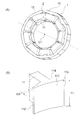
- FIG. 11A is a perspective view showing the outer shape of the stator 1.
- FIG. 11B is a perspective view showing the shape of the tip 111 of the tooth 11.
- the tip portion 111 of the tooth 11 has a shape in which the radial length (width) decreases as the end portion 112 in the circumferential direction approaches.
- the end 112 of the tip 111 of the tooth 11 has a rectangular end surface facing the gap 15 described above.
- W1 radial length of the end 112
- T1 the axial length of the teeth 11
- W1 ⁇ T1 the area of the end 112 is represented by W1 ⁇ T1.
- Stator core 10 (teeth 11 and yoke 12) is made of an electromagnetic steel sheet mainly composed of iron.
- the magnetic flux density exceeds 1.6 T, the magnetic steel sheet is magnetically saturated, the magnetic permeability decreases, and the magnetic resistance increases accordingly.
- the magnetic flux generated by the current of the coil 2 passes through the end portion 112 of the tooth 11 and flows to the adjacent tooth 11 through the gap 15.
- the magnetic flux density at the end 112 of the tooth 11 is represented by ⁇ / (W1 ⁇ T1). Therefore, if it is configured to satisfy ⁇ / (W1 ⁇ T1)> 1.6 (T), the magnetic resistance when the magnetic flux passes through the end 112 of the tooth 11 can be increased. As a result, the magnetic flux flowing from the teeth 11 to the permanent magnet 5 can be reduced, and the effect of suppressing the demagnetization of the permanent magnet 5 can be further enhanced.
- the groove 55 is formed on the surface of the permanent magnet 5 and in the inter-electrode portion 53, and the width L ⁇ b> 2 of the groove 55 and the distance between the tip portions 111 of the adjacent teeth 11.
- L1 satisfies 1.00 ⁇ L2 / L1 ⁇ 3.75. Therefore, demagnetization of the permanent magnet 5 due to the magnetic flux flowing from the tooth 11 to the permanent magnet 5 can be effectively suppressed.
- the groove 55 of the permanent magnet 5 has a shape whose width becomes narrower toward the inner side in the radial direction, the effect of suppressing demagnetization is obtained and the area of the permanent magnet 5 in the cross section orthogonal to the axis C1 is reduced. Can be suppressed. That is, a decrease in magnetic flux generated by the permanent magnet 5 can be suppressed, and a decrease in motor efficiency can be suppressed.
- the area S1 of the permanent magnet 5 and the area S0 of the annular portion surrounded by the circle B1 in contact with the outer periphery of the permanent magnet 5 and the circle B2 in contact with the inner periphery are (S0 ⁇ S1) / S1 ⁇ 100> 4. .. 20% and the effect of suppressing the demagnetization of the permanent magnet 5 can be enhanced by the configuration in which the angle ⁇ of the groove side portion 55a is 30 ° or more.
- the radial length W1 of the end 112 in the circumferential direction of the tooth 11, the axial length T1 of the tooth 11, and the magnetic flux ⁇ generated in the tooth 11 are ⁇ / (W1 ⁇ T1)> 1.
- FIG. 12 is a diagram illustrating the shape of the stator core 10 of the electric motor according to the modification of the first embodiment.
- the intervals between the tip portions 111 of the adjacent teeth 11 are all constant.
- tip part 111 of the adjacent teeth 11 is not constant, but changes regularly.
- Such a motor is also referred to as an unequal pitch motor.
- the nine teeth 11 are sequentially designated as teeth 11a, 11b, 11c, 11d, 11e, 11f, 11g, 11h, and 11i.
- the interval between the tips 111 of the teeth 11a and 11b is La
- the interval between the tips 111 of the teeth 11b and 11c is Lb
- the interval between the tips 111 of the teeth 11c and 11d is Lc.
- the intervals La, Lb, and Lc are different from each other.
- the interval La is the widest.
- the distance between the tips 111 of the teeth 11d and 11e is set to La which is the same as the distance between the tips 111 of the teeth 11a and 11b, and the distance between the tips 111 of the teeth 11e and 11f is set between the tips 111 of the teeth 11b and 11c.
- the distance Lb is the same as the distance
- the distance between the tips 111 of the teeth 11f and 11g is the same Lc as the distance between the tips 111 of the teeth 11c and 11d.
- the interval between the tips 111 of the teeth 11g and 11h is La
- the interval between the tips 111 of the teeth 11h and 11i is Lb
- the interval between the tips 111 of the teeth 11h and 11a is Lc.
- the intervals La, Lb, and Lc are as described above.
- the magnetic flux that causes demagnetization of the permanent magnet 5 is the magnetic flux that flows from the circumferential end 112 of the tip 111 of the tooth 11 to the permanent magnet 5. Therefore, the magnetic flux reaches a wider range of the permanent magnet 5 in the portion where the distance between the tip portions 111 of the teeth 11 is wide.
- the widest interval La among the intervals La, Lb, and Lc of the tips 111 of the teeth 11a to 11i is configured to satisfy the condition of L1 described in the first embodiment. . That is, 1.00 ⁇ L2 / La ⁇ 3.75 is established.
- L2 is the width
- the distance La between the tip 111 of the tooth 11a (first tooth) and the tip 111 of the tooth 11b (second tooth) is equal to the tip 111 of the tooth 11b and the tooth 11c (first). 3) and wider than the distance Lc between the tip 111 of the tooth 11c and the tip 111 of the tooth 11d (fourth tooth). 1.00 ⁇ L2 / La ⁇ 3.75 is satisfied.
- the teeth 11a to 11i have three intervals La, Lb, and Lc has been described. However, if there is at least one interval different from other intervals among the intervals between the plurality of teeth 11 of the stator 1. Of these, the widest interval La may satisfy 1.00 ⁇ L2 / La ⁇ 3.75.
- the widest distance La and the width L2 of the width 55 of the permanent magnet 5 are 1.00 ⁇ L2 / La ⁇ .
- FIG. 13 is a diagram illustrating the shape of the permanent magnet 500 of the electric motor according to the second embodiment.
- the permanent magnet 5 (FIG. 1) of Embodiment 1 was oriented in the radial direction (radial orientation).
- the permanent magnet 500 of the second embodiment is oriented (polar orientation) so as to connect adjacent magnetic poles.
- the permanent magnet 500 has a magnetic pole 501 (first magnetic pole) and a magnetic pole 502 (second magnetic pole) on the surface (outer peripheral surface).
- the magnetic poles 501 and 502 are alternately arranged in the circumferential direction.
- the magnetic pole 501 is an N pole
- the magnetic pole 502 is an S pole.
- a magnetic path is formed in an arc shape so as to go from the magnetic pole 502 (S pole) to the magnetic pole 501 (N pole).
- a pole portion 503 is formed between the magnetic pole 501 and the magnetic pole 502.
- the permanent magnet 500 When the magnetic flux flows from the teeth 11 in the opposite direction to the arc-shaped magnetic path in the permanent magnet 500, the permanent magnet 500 is likely to be demagnetized. Since the surface portion of the inter-pole portion 503 has a short magnetic path, demagnetization is particularly easily generated. Therefore, a groove 505 is formed in the interpolar part 503 on the surface of the permanent magnet 500 to suppress demagnetization.
- the groove 505 crosses the magnetic path in the permanent magnet 500, so that the demagnetizing field increases and the permeance coefficient decreases. Occurs.
- the permeance coefficient decreases, the magnetic flux generated by the permanent magnet 500 decreases, leading to a decrease in motor efficiency.
- the width of the groove 505 is configured to be narrower toward the inner side in the radial direction (see FIG. 7B).
- the vertical axis in FIG. 14 represents the induced voltage drop rate.
- the induced voltage corresponds to the magnetic force of the permanent magnet 500, and thus corresponds to the generated torque.
- a decrease in induced voltage leads to a decrease in torque, that is, a decrease in motor efficiency.
- the induced voltage reduction rate indicates how much the induced voltage has decreased with reference to the induced voltage when the groove 505 is not formed in the permanent magnet 500 (100%).
- the horizontal axis in FIG. 14 indicates the area ratio of the groove 505. The method for calculating the area ratio of the groove 505 is as described with reference to FIG.
- a line segment D1 shows a change in the induced voltage drop rate when the width of the groove 505 is the same between the radially outer side and the inner side
- a line segment D2 is a case where the width of the groove 505 becomes narrower on the radially inner side.
- the change in the induced voltage drop rate is shown. Comparing the line segment D1 and the line segment D2, even when the area ratio of the groove 505 is the same, the induced voltage is reduced when the width of the groove 505 is narrower on the inner side in the radial direction (line segment D2). I understand that there are few.
- the configuration in which the width of the groove 505 of the permanent magnet 500 narrows radially inward can not only suppress demagnetization, but also suppress a decrease in magnetic flux generated by the permanent magnet 500 (that is, a decrease in motor efficiency).
- a decrease in motor efficiency By suppressing the decrease in the magnetic flux generated by the permanent magnet 500, as described in the first embodiment, the current required to output an arbitrary torque is reduced. Therefore, the magnetic flux flowing from the teeth 11 to the permanent magnet 500 is reduced, and demagnetization is less likely to occur.
- the electric motor according to the second embodiment is configured in the same manner as the electric motor according to the first embodiment except for the configuration of the permanent magnet 500.
- the permanent magnet 500 is pole-oriented so as to connect the adjacent magnetic poles 501 and 502, and the groove 505 is formed in the inter-electrode portion 503 on the surface of the permanent magnet 500. ing. Therefore, demagnetization can also be suppressed in the pole-oriented permanent magnet 500. Further, since the groove 505 of the permanent magnet 5 has a shape whose width becomes narrower toward the inner side in the radial direction, the portion where the permanent magnet 5 crosses the magnetic path is reduced, thereby suppressing a reduction in motor efficiency. .
- FIG. 15 is a diagram showing the shape of permanent magnet 500A of the electric motor according to the third embodiment.
- the permanent magnet 500A of the third embodiment is different from the permanent magnet 500 of the second embodiment described above in the shape of the groove 506.
- the permanent magnet 500A of the third embodiment is polar-oriented. Further, magnetic poles 501 and 502 are alternately arranged in the circumferential direction on the surface (outer peripheral surface) of the permanent magnet 500A. A pole portion 503 is formed between the magnetic pole 501 and the magnetic pole 502.
- a groove 506 is formed in the inter-electrode portion 503 on the surface of the permanent magnet 500A.
- the groove 506 has a shape whose width becomes narrower toward the radially inner side (axis C1 side). Further, in the third embodiment, the groove 506 has a curved shape along the orientation direction of the permanent magnet 500 ⁇ / b> A, in other words, a curved shape along the magnetic path between the magnetic poles 501 and 502.
- the curved shape is, for example, an arc shape.
- the permeance coefficient is reduced, which causes a reduction in motor efficiency.
- the groove 506 has a curved shape along the orientation direction of the permanent magnet 500A, the magnetic path is not blocked. Therefore, a decrease in magnetic flux generated by permanent magnet 500A can be suppressed, and a decrease in motor efficiency can be suppressed.
- the current required to output an arbitrary torque is reduced. Therefore, the magnetic flux flowing from the teeth 11 to the permanent magnet 500A is reduced, and demagnetization is less likely to occur.
- the electric motor of the third embodiment is configured in the same manner as the electric motor of the first embodiment except for the configuration of the permanent magnet 500A.
- the permanent magnet 500A is pole-oriented, and the groove 506 formed in the interpolar portion 503 on the surface of the permanent magnet 500A is along the orientation direction of the permanent magnet 500A. It has a curved shape. Therefore, the groove 506 can be prevented from crossing the magnetic path of the permanent magnet 500A, and a reduction in motor efficiency can be suppressed.
- Embodiment 2 may apply the structure of the electric motor in which the space
- FIG. 16 is a diagram illustrating a configuration of the electric motor according to the fourth embodiment.
- the electric motor 101 of the fourth embodiment is different from the electric motor 100 of the first embodiment in the number of teeth 11 and the winding pattern of the coil 2.
- the stator 1 has twelve teeth 11.
- the twelve teeth 11 are sequentially designated as teeth 11a, 11b, 11c, 11d, 11e, 11f, 11g, 11h, 11i, 11j, 11k, and 11l.
- the coils 2 wound in concentrated winding around the teeth 11a, 11b, 11c, 11d, 11e, 11f, 11g, 11h, 11i, 11j, 11k, and 11l are respectively connected to the coils 2a, 2b, 2c, 2d, 2e, 2f, 2g, 2h, 2i, 2j, 2k, 2l.
- the U-phase current flows through the coils 2a and 2f.
- a W-phase current flows through the coils 2b and 2i.
- a V-phase current flows through the coils 2e and 2j.
- a U-bar phase current having an opposite phase to the U phase (that is, the phase is inverted by 180 degrees) flows through the coils 2g and 2l.
- a W bar phase current having a phase opposite to the W phase flows through the coils 2c and 2h.
- the coils 2d and 2k pass a V-bar current that is opposite in phase to the V-phase.
- a U-phase current flows through the coil 2a wound around the tooth 11a, and a U-bar phase current flows through the coil 2l wound around the adjacent tooth 11l.
- a W-phase current flows through the coil 2b wound around the tooth 11b, and a W-bar phase current flows through the coil 2c wound around the adjacent tooth 11c.
- a V-bar current flows through the coil 2d wound around the tooth 11d, and a V-phase current flows through the coil 2e wound around the tooth 11e.
- a U-phase current flows through the coil 2f wound around the tooth 11f
- a U-bar phase current flows through the coil 2g wound around the adjacent tooth 11g
- a W-bar phase current flows through the coil 2h wound around the tooth 11h
- a W-phase current flows through the coil 2i wound around the adjacent tooth 11i
- a V-phase current flows through the coil 2j wound around the tooth 11j
- a V-bar phase current flows through the coil 2k wound around the adjacent tooth 11k.
- the coil 2a first coil
- the coil 2l wound around the adjacent tooth 11l (second tooth)
- most of the magnetic flux generated in the teeth 11a flows in the teeth 11l. Therefore, the amount of magnetic flux that flows between the tip portion 111 of the tooth 11a and the tip portion 111 of the tooth 11l also increases, and as a result, the magnetic flux that flows in the permanent magnet 5 also increases. In other words, a stronger magnetic field acts on the permanent magnet 5 from the teeth 11a and 11l.
- a current having an opposite phase to the coil 2 wound around the adjacent tooth 11 flows through the coil 2 wound around any of the teeth 11.
- the configuration is limited to such a configuration. Is not to be done. Of the plurality of teeth 11, it is sufficient that a current having an opposite phase flows through the coil 2 wound around at least two adjacent teeth 11.
- the electric motor of the fourth embodiment is configured similarly to the electric motor of the first embodiment except for the above configuration.
- the groove 55 is formed in the inter-electrode portion 53 on the surface of the permanent magnet 5. Is formed. Therefore, demagnetization of the permanent magnet 5 can be suppressed even when the amount of magnetic flux flowing from the tip 111 of the tooth 11 to the permanent magnet 5 is large.
- the configuration of the electric motor in which the distance between the tips 111 of the teeth 11 described in the modification of the first embodiment is not constant may be applied to the fourth embodiment, and also described in the second and third embodiments.
- the permanent magnet pole orientation and groove shape may be applied.
- FIG. 17 is a diagram illustrating a configuration of the electric motor according to the fifth embodiment.
- the electric motor 102 of the fifth embodiment is different from the electric motor 100 of the first embodiment in that the rotor 9 has an outer rotor type configuration in which the rotor 9 is disposed outside the stator 8.
- the stator 8 includes, for example, a stator core 80 made of a laminated body of electromagnetic steel plates and a coil 7 wound around the stator core 80.
- the stator core 80 has an annular yoke 82 centered on the axis C ⁇ b> 1 and a plurality of teeth 81 extending radially outward from the yoke 82.
- the teeth 81 are formed at equal intervals in the circumferential direction around the axis C1.
- a tip portion 81 a having a wider width (dimension in the circumferential direction) than other portions of the tooth 81 is formed at the tip end on the radially outer side of the tooth 81.
- the distal end portion 81a has end portions 85 at both ends in the circumferential direction.
- the interval between the tips 81a of adjacent teeth 81 is defined as an interval L1.
- the rotor 9 has permanent magnets 90 arranged in a ring around the stator 8.
- the permanent magnet 90 has magnetic poles 91 and 92 that are alternately arranged in the circumferential direction around the axis C1.
- the permanent magnet 90 has eight poles and has four magnetic poles 91 and four magnetic poles 92, but the number of poles is not limited to eight.
- the material of the permanent magnet 90 is as described in the first embodiment.
- the rotor 9 is attached to the shaft via a hub (not shown), and the axis C1 is the rotation center of the shaft.
- an inter-electrode portion 93 is formed between the magnetic poles 91 and 92 of the permanent magnet 90.
- a groove 95 is formed in the inner peripheral surface (surface) of the permanent magnet 90 and in the inter-electrode portion 93.
- the groove 95 extends in the axial direction.
- the width in the circumferential direction of the groove 95 is defined as a width L2.
- the magnetic flux generated by the current flowing through the coil 7 wound around the tooth 81 flows to the adjacent tooth 81 through the surface portion of the rotor 9 facing the tip 81a of the tooth 81.
- the magnetic flux flowing through the permanent magnet 90 increases. In particular, demagnetization is likely to occur in the inter-pole portion 93 of the magnetic poles 91 and 92.
- a groove 95 is formed on the surface (inner peripheral surface) of the permanent magnet 90 and in the inter-pole portion 93 (that is, the portion most easily demagnetized by the permanent magnet 90). Demagnetization is suppressed.
- the distance L1 between the tips 81a of the teeth 81 and the width L2 of the groove 95 of the permanent magnet 90 satisfy 1.00 ⁇ L2 / L1 ⁇ 3.75.
- the width L2 of the groove 95 is wider than the interval L1 between the tips 81a of the adjacent teeth 81, and is equal to or less than 3.75 times the interval L1.
- the groove 95 has a shape in which the width becomes narrower toward the outer side in the radial direction (that is, as the distance from the stator 8 becomes longer). Thereby, demagnetization of the permanent magnet 90 can be suppressed, and a decrease in the area ratio of the groove 95 can be suppressed, so that a decrease in motor efficiency can be suppressed.
- the area S1 of the permanent magnet 90 and the area S0 of the annular portion surrounded by the circle in contact with the outer periphery of the permanent magnet 90 and the circle in contact with the inner periphery are (S0-S1) / S1. It is desirable that x100> 4.20% is satisfied, and the angle ⁇ of the groove side portion 95a at the circumferential end of the groove 95 is 30 ° or more. Thereby, as explained in the first embodiment, the effect of suppressing the demagnetization of the permanent magnet 90 can be enhanced.
- the radial length W1 of the circumferential end portion 85 of the tooth 81, the axial length T1 of the tooth 81, and the magnetic flux ⁇ generated in the tooth 81 are ⁇ / (W1 ⁇ T1)> 1.6 ( It is desirable to satisfy T).
- the groove 95 is formed in the inter-electrode portion 93 on the surface (inner peripheral surface) of the permanent magnet 90, and the width L2 of the groove 95 and the tip of the adjacent teeth 81 are formed.
- the interval L1 between the portions 81a satisfies 1.00 ⁇ L2 / L1 ⁇ 3.75. Therefore, demagnetization of the permanent magnet 90 can be effectively suppressed.
- the configuration of the electric motor in which the distance between the tips 111 of the teeth 11 described in the modification of the first embodiment is not constant may be applied to the fifth embodiment, and also described in the second and third embodiments.
- the permanent magnet pole orientation and groove shape may be applied.
- the winding pattern described in the fourth embodiment may be applied.
- FIG. 18 is a diagram showing a configuration of an air conditioner 300 using the electric motor 100 of the first embodiment.
- the air conditioner 300 includes an outdoor unit 301, an indoor unit 302, and a refrigerant pipe 303 that connects them.
- the outdoor unit 301 includes an outdoor blower 305 as a blower.
- FIG. 19A is a front view showing the configuration of the outdoor unit 301.
- FIG. 19B is a cross-sectional view taken along line 19B-19B shown in FIG.
- the outdoor unit 301 includes a housing 306 and a frame 307 fixed in the housing 306.
- An electric motor 100 as a drive source of the outdoor fan 305 is fixed to the frame 307.
- An impeller 304 is attached to the shaft 40 of the electric motor 100 via a hub 308.
- the outdoor fan 305 is configured by the electric motor 100, the hub 308, and the impeller 304.
- FIG. 19A also shows a compressor 309 that compresses the refrigerant.
- the impeller 304 attached to the shaft 40 rotates and blows air to the outside.
- the heat released when the refrigerant compressed by the compressor 309 is condensed by a condenser (not shown) is released to the outside by the ventilation of the outdoor blower 305.
- the electric motor 100 according to the first embodiment described above suppresses the demagnetization of the permanent magnet 5 and improves the motor efficiency. Therefore, by using the electric motor 100 as a power source of the outdoor blower 305, it is possible to improve the operation efficiency of the air conditioner 300 over a long period of time and to reduce energy consumption. The same applies to the case where the electric motor according to another embodiment is used as a power source for the outdoor fan 305.
- each embodiment was used for the outdoor air blower 305 of the outdoor unit 301 here, you may use the electric motor of each embodiment for the air blower of the indoor unit 302.
- stator 10 stator core, 11, 11a, 11b, 11c, 11d, 11e, 11f, 11g, 11h, 11i, 11j, 11k, 11l teeth, 12 yokes, 14 slots, 15 slot openings, 2, 2a, 2b, 2c, 2d, 2e, 2f, 2g, 2h, 2i, 2j, 2k, 2l coils, 3 insulators, 4 rotors, 40 shafts, 41 resin parts, 5 permanent magnets, 51 magnetic poles, 52 magnetic poles, 53 poles Part, 55 groove, 55a end face, 7 coils, 8 stators, 9 rotors, 80 stator cores, 81 teeth, 81a tip, 82 yoke, 85 ends, 90 permanent magnets, 91, 92 magnetic poles, 93 poles Part, 95 groove, 100, 101, 102 Electric motor, 111 tip, 112 tip, 113 tip, 300 air conditioner, 301 outdoor unit, 302 indoor unit, 303 refrigerant piping, 304
Landscapes
- Engineering & Computer Science (AREA)
- Power Engineering (AREA)
- Chemical & Material Sciences (AREA)
- Combustion & Propulsion (AREA)
- Mechanical Engineering (AREA)
- General Engineering & Computer Science (AREA)
- Iron Core Of Rotating Electric Machines (AREA)
- Permanent Field Magnets Of Synchronous Machinery (AREA)
Abstract
Un moteur comprend : une culasse en forme d'anneau comportant une ligne d'arbre comme centre; un stator comportant une première dent et une seconde dent s'étendant de la culasse au côté circonférentiel interne ou au côté circonférentiel externe; et un rotor qui est un rotor qui peut tourner avec ladite ligne d'arbre servant de centre, ledit rotor comportant un aimant permanent sur la surface opposée au stator. La première dent et la seconde dent ont toutes deux une partie pointe opposée à l'aimant permanent. L'aimant permanent comprend : un premier pôle magnétique et un second pôle magnétique adjacents dans la direction circonférentielle avec ladite ligne d'arbre servant de centre; et une rainure formée au niveau de la partie entre pôles du premier pôle magnétique et du second pôle magnétique. Un espace L1 de la direction circonférentielle de la partie pointe de la première dent et de la partie pointe de la seconde dent, et une largeur L2 de la direction circonférentielle de la rainure satisfont à 1,00 < L2/L1 ≤ 3,75.
Priority Applications (4)
| Application Number | Priority Date | Filing Date | Title |
|---|---|---|---|
| PCT/JP2016/079570 WO2018066084A1 (fr) | 2016-10-05 | 2016-10-05 | Moteur et dispositif de climatisation |
| JP2018543523A JP6615375B2 (ja) | 2016-10-05 | 2016-10-05 | 電動機および空気調和装置 |
| CN201680089231.1A CN109792174B (zh) | 2016-10-05 | 2016-10-05 | 电动机以及空气调节装置 |
| US16/323,361 US10784733B2 (en) | 2016-10-05 | 2016-10-05 | Motor and air conditioning apparatus |
Applications Claiming Priority (1)
| Application Number | Priority Date | Filing Date | Title |
|---|---|---|---|
| PCT/JP2016/079570 WO2018066084A1 (fr) | 2016-10-05 | 2016-10-05 | Moteur et dispositif de climatisation |
Publications (1)
| Publication Number | Publication Date |
|---|---|
| WO2018066084A1 true WO2018066084A1 (fr) | 2018-04-12 |
Family
ID=61831722
Family Applications (1)
| Application Number | Title | Priority Date | Filing Date |
|---|---|---|---|
| PCT/JP2016/079570 Ceased WO2018066084A1 (fr) | 2016-10-05 | 2016-10-05 | Moteur et dispositif de climatisation |
Country Status (4)
| Country | Link |
|---|---|
| US (1) | US10784733B2 (fr) |
| JP (1) | JP6615375B2 (fr) |
| CN (1) | CN109792174B (fr) |
| WO (1) | WO2018066084A1 (fr) |
Cited By (5)
| Publication number | Priority date | Publication date | Assignee | Title |
|---|---|---|---|---|
| WO2020162232A1 (fr) * | 2019-02-05 | 2020-08-13 | 株式会社デンソー | Moteur rotatif |
| CN112970175A (zh) * | 2018-11-02 | 2021-06-15 | Lg伊诺特有限公司 | 电动机 |
| CN113519112A (zh) * | 2019-03-08 | 2021-10-19 | 三菱电机株式会社 | 马达、风扇以及空气调节机 |
| WO2022091198A1 (fr) * | 2020-10-27 | 2022-05-05 | 三菱電機株式会社 | Machine électrique tournante et dispositif de direction assistée électrique |
| WO2025088786A1 (fr) * | 2023-10-27 | 2025-05-01 | 三菱電機株式会社 | Moteur, soufflante et dispositif de climatisation |
Families Citing this family (3)
| Publication number | Priority date | Publication date | Assignee | Title |
|---|---|---|---|---|
| FR3067880B1 (fr) * | 2017-06-15 | 2020-07-17 | Moteurs Leroy-Somer | Machine electrique tournante |
| CN110912289B (zh) * | 2019-12-09 | 2025-04-29 | 珠海格力电器股份有限公司 | 单相永磁电机及具有其的吸尘器 |
| JP7629583B1 (ja) * | 2024-07-23 | 2025-02-13 | マブチモーター株式会社 | ハウジング、モータ及びブロア |
Citations (4)
| Publication number | Priority date | Publication date | Assignee | Title |
|---|---|---|---|---|
| JPH07135758A (ja) * | 1994-02-07 | 1995-05-23 | Mitsubishi Steel Mfg Co Ltd | モータ |
| JP2004088855A (ja) * | 2002-08-23 | 2004-03-18 | Mitsubishi Electric Corp | Dcモータの回転子及びdcモータ |
| JP2007074888A (ja) * | 2004-12-17 | 2007-03-22 | Hitachi Metals Ltd | モータ用回転子およびその製造方法 |
| JP2016077093A (ja) * | 2014-10-07 | 2016-05-12 | 三菱電機株式会社 | 空気調和機 |
Family Cites Families (24)
| Publication number | Priority date | Publication date | Assignee | Title |
|---|---|---|---|---|
| JP3376373B2 (ja) * | 1995-06-07 | 2003-02-10 | ミネベア株式会社 | モータ構造 |
| US6784582B1 (en) * | 2001-11-19 | 2004-08-31 | Valeo Electrical Systems, Inc. | Magnet shaping and pole concentration for reduction of cogging torque in permanent magnet motors |
| JP4126992B2 (ja) | 2002-08-27 | 2008-07-30 | 三菱電機株式会社 | 永久磁石型モータおよびそれを具備した電動パワーステアリング装置 |
| JP4065829B2 (ja) * | 2003-10-10 | 2008-03-26 | 本田技研工業株式会社 | 永久磁石式回転子およびブラシレスモータ |
| JP2005328588A (ja) * | 2004-05-12 | 2005-11-24 | Mitsubishi Electric Corp | 永久磁石電動機 |
| JP2006086319A (ja) * | 2004-09-16 | 2006-03-30 | Mitsubishi Electric Corp | リング型焼結磁石 |
| KR100908424B1 (ko) | 2004-12-17 | 2009-07-21 | 히타치 긴조쿠 가부시키가이샤 | 자기 회로용 부품 및 그 제조 방법 |
| WO2006064589A1 (fr) * | 2004-12-17 | 2006-06-22 | Hitachi Metals, Ltd. | Rotor pour moteur et son procede de fabrication |
| JP2008043031A (ja) * | 2006-08-04 | 2008-02-21 | Mabuchi Motor Co Ltd | リング形状界磁マグネットに薄肉部を形成した小型モータ |
| TWI343689B (en) * | 2006-12-28 | 2011-06-11 | Delta Electronics Inc | Permanent magnet rotary structure of electric machinery |
| CN101222154B (zh) * | 2007-01-12 | 2010-07-28 | 台达电子工业股份有限公司 | 永磁电机的转动结构 |
| DE102009061032A1 (de) * | 2009-05-15 | 2010-11-18 | Tyco Electronics Belgium Ec Bvba | Magnetoelektronischer Winkelsensor, insbesondere Reluktanzresolver |
| JP5183601B2 (ja) | 2009-09-16 | 2013-04-17 | 三菱電機株式会社 | 同期電動機の回転子及び同期電動機 |
| JP5806073B2 (ja) * | 2010-10-19 | 2015-11-10 | アスモ株式会社 | ブラシレスモータ |
| JP5889534B2 (ja) * | 2011-02-01 | 2016-03-22 | 日本電産テクノモータ株式会社 | ブラシレスdcモータ |
| JP5937432B2 (ja) * | 2011-07-25 | 2016-06-22 | アスモ株式会社 | モータ |
| WO2013035349A1 (fr) | 2011-09-08 | 2013-03-14 | 三菱電機株式会社 | Moteur et pompe, unité de climatisation, unité d'approvisionnement en eau chaude et unité de source de chaleur en étant équipée |
| US20130169099A1 (en) * | 2011-12-31 | 2013-07-04 | Danotek Motion Technologies, Inc. | Magnet assembly for permanent magnet machine |
| KR101897301B1 (ko) * | 2012-12-11 | 2018-09-10 | 현대자동차주식회사 | 매입형 영구자석 동기전동기 |
| CN104600888B (zh) * | 2013-10-31 | 2019-01-18 | 株式会社电装 | 转子以及电动机 |
| US9515528B2 (en) * | 2014-01-06 | 2016-12-06 | Mitsubishi Electric Corporation | Permanent magnet rotary electric machine |
| JP6270876B2 (ja) * | 2014-01-09 | 2018-01-31 | 三菱電機株式会社 | 同期電動機の駆動回路および、その駆動回路により駆動される同期電動機および、その同期電動機を用いた送風機および、その送風機を用いた空気調和機 |
| DE102015212165A1 (de) * | 2015-06-30 | 2017-01-05 | Robert Bosch Gmbh | Elektrische Maschine mit reduziertem Nutrasten und Drehmomentwelligkeit |
| CN107887994A (zh) * | 2016-09-30 | 2018-04-06 | 德昌电机(深圳)有限公司 | 电机及其转子 |
-
2016
- 2016-10-05 CN CN201680089231.1A patent/CN109792174B/zh not_active Expired - Fee Related
- 2016-10-05 WO PCT/JP2016/079570 patent/WO2018066084A1/fr not_active Ceased
- 2016-10-05 US US16/323,361 patent/US10784733B2/en active Active
- 2016-10-05 JP JP2018543523A patent/JP6615375B2/ja not_active Expired - Fee Related
Patent Citations (4)
| Publication number | Priority date | Publication date | Assignee | Title |
|---|---|---|---|---|
| JPH07135758A (ja) * | 1994-02-07 | 1995-05-23 | Mitsubishi Steel Mfg Co Ltd | モータ |
| JP2004088855A (ja) * | 2002-08-23 | 2004-03-18 | Mitsubishi Electric Corp | Dcモータの回転子及びdcモータ |
| JP2007074888A (ja) * | 2004-12-17 | 2007-03-22 | Hitachi Metals Ltd | モータ用回転子およびその製造方法 |
| JP2016077093A (ja) * | 2014-10-07 | 2016-05-12 | 三菱電機株式会社 | 空気調和機 |
Cited By (12)
| Publication number | Priority date | Publication date | Assignee | Title |
|---|---|---|---|---|
| CN112970175A (zh) * | 2018-11-02 | 2021-06-15 | Lg伊诺特有限公司 | 电动机 |
| CN112970175B (zh) * | 2018-11-02 | 2023-12-12 | Lg伊诺特有限公司 | 电动机 |
| WO2020162232A1 (fr) * | 2019-02-05 | 2020-08-13 | 株式会社デンソー | Moteur rotatif |
| JP2020127319A (ja) * | 2019-02-05 | 2020-08-20 | 株式会社デンソー | 回転電機 |
| CN113412570A (zh) * | 2019-02-05 | 2021-09-17 | 株式会社电装 | 旋转电机 |
| JP7255214B2 (ja) | 2019-02-05 | 2023-04-11 | 株式会社デンソー | 回転電機 |
| CN113412570B (zh) * | 2019-02-05 | 2025-04-11 | 株式会社电装 | 旋转电机 |
| CN113519112A (zh) * | 2019-03-08 | 2021-10-19 | 三菱电机株式会社 | 马达、风扇以及空气调节机 |
| US20220140672A1 (en) * | 2019-03-08 | 2022-05-05 | Mitsubishi Electric Corporation | Electric motor, fan, and air conditioner |
| WO2022091198A1 (fr) * | 2020-10-27 | 2022-05-05 | 三菱電機株式会社 | Machine électrique tournante et dispositif de direction assistée électrique |
| US12506373B2 (en) | 2020-10-27 | 2025-12-23 | Mitsubishi Electric Corporation | Electric rotating machine and electric power steering apparatus |
| WO2025088786A1 (fr) * | 2023-10-27 | 2025-05-01 | 三菱電機株式会社 | Moteur, soufflante et dispositif de climatisation |
Also Published As
| Publication number | Publication date |
|---|---|
| JP6615375B2 (ja) | 2019-12-04 |
| US20200021151A1 (en) | 2020-01-16 |
| CN109792174B (zh) | 2020-11-10 |
| US10784733B2 (en) | 2020-09-22 |
| CN109792174A (zh) | 2019-05-21 |
| JPWO2018066084A1 (ja) | 2019-03-28 |
Similar Documents
| Publication | Publication Date | Title |
|---|---|---|
| JP6615375B2 (ja) | 電動機および空気調和装置 | |
| JP6964672B2 (ja) | ロータ、電動機、送風機および空気調和装置 | |
| JP5816822B2 (ja) | モータおよびそれを搭載した電気機器 | |
| CN102656774B (zh) | 轴向间隙电动机 | |
| JP5491484B2 (ja) | スイッチドリラクタンスモータ | |
| JPWO2019049203A1 (ja) | コンシクエントポール型ロータ、電動機、圧縮機、送風機、及び空気調和機 | |
| US12542459B2 (en) | Electric motor | |
| WO2020261420A1 (fr) | Rotor, moteur, ventilateur, climatiseur et procédé de fabrication d'un rotor | |
| JPWO2020129123A1 (ja) | 回転子、電動機、送風機、及び空気調和機、並びに回転子の製造方法 | |
| JPWO2018016026A1 (ja) | モータ及び空気調和機 | |
| CN116941160A (zh) | 励磁子 | |
| JP7098047B2 (ja) | モータ、ファン、および空気調和機 | |
| JP7026805B2 (ja) | ステータ、モータ、ファン、及び空気調和機並びにステータの製造方法 | |
| CN104662778B (zh) | 径向间隙型旋转电机、送风机、压缩机和空调机 | |
| JP5128800B2 (ja) | ハイブリッド式永久磁石回転電機 | |
| TW202203549A (zh) | 旋轉電機 | |
| JP7006103B2 (ja) | ロータ及びモータ | |
| JP3999358B2 (ja) | 円筒ラジアルギャップ型回転電機 | |
| WO2023073757A1 (fr) | Rotor, moteur électrique, ventilateur et climatiseur | |
| JP2007306685A (ja) | 回転電機並びに送風機及び冷媒圧縮機 | |
| WO2023148953A1 (fr) | Rotor, moteur électrique, soufflante d'air, dispositif de climatisation et procédé de production de moteur électrique | |
| CN117501591A (zh) | 转子及其制造方法以及电动机 | |
| CN104067483A (zh) | 同步电动机的转子及其制造方法、以及同步电动机 |
Legal Events
| Date | Code | Title | Description |
|---|---|---|---|
| ENP | Entry into the national phase |
Ref document number: 2018543523 Country of ref document: JP Kind code of ref document: A |
|
| 121 | Ep: the epo has been informed by wipo that ep was designated in this application |
Ref document number: 16918283 Country of ref document: EP Kind code of ref document: A1 |
|
| NENP | Non-entry into the national phase |
Ref country code: DE |
|
| 122 | Ep: pct application non-entry in european phase |
Ref document number: 16918283 Country of ref document: EP Kind code of ref document: A1 |