WO2018066475A1 - パルプモールド容器及びパルプモールド容器の製造方法 - Google Patents
パルプモールド容器及びパルプモールド容器の製造方法 Download PDFInfo
- Publication number
- WO2018066475A1 WO2018066475A1 PCT/JP2017/035508 JP2017035508W WO2018066475A1 WO 2018066475 A1 WO2018066475 A1 WO 2018066475A1 JP 2017035508 W JP2017035508 W JP 2017035508W WO 2018066475 A1 WO2018066475 A1 WO 2018066475A1
- Authority
- WO
- WIPO (PCT)
- Prior art keywords
- synthetic resin
- container
- resin layer
- pulp mold
- container body
- Prior art date
- Legal status (The legal status is an assumption and is not a legal conclusion. Google has not performed a legal analysis and makes no representation as to the accuracy of the status listed.)
- Ceased
Links
Images



Classifications
-
- B—PERFORMING OPERATIONS; TRANSPORTING
- B65—CONVEYING; PACKING; STORING; HANDLING THIN OR FILAMENTARY MATERIAL
- B65D—CONTAINERS FOR STORAGE OR TRANSPORT OF ARTICLES OR MATERIALS, e.g. BAGS, BARRELS, BOTTLES, BOXES, CANS, CARTONS, CRATES, DRUMS, JARS, TANKS, HOPPERS, FORWARDING CONTAINERS; ACCESSORIES, CLOSURES, OR FITTINGS THEREFOR; PACKAGING ELEMENTS; PACKAGES
- B65D65/00—Wrappers or flexible covers; Packaging materials of special type or form
- B65D65/38—Packaging materials of special type or form
- B65D65/42—Applications of coated or impregnated materials
-
- B—PERFORMING OPERATIONS; TRANSPORTING
- B32—LAYERED PRODUCTS
- B32B—LAYERED PRODUCTS, i.e. PRODUCTS BUILT-UP OF STRATA OF FLAT OR NON-FLAT, e.g. CELLULAR OR HONEYCOMB, FORM
- B32B23/00—Layered products comprising a layer of cellulosic plastic substances, i.e. substances obtained by chemical modification of cellulose, e.g. cellulose ethers, cellulose esters, viscose
- B32B23/04—Layered products comprising a layer of cellulosic plastic substances, i.e. substances obtained by chemical modification of cellulose, e.g. cellulose ethers, cellulose esters, viscose comprising such cellulosic plastic substance as the main or only constituent of a layer, which is next to another layer of the same or of a different material
- B32B23/08—Layered products comprising a layer of cellulosic plastic substances, i.e. substances obtained by chemical modification of cellulose, e.g. cellulose ethers, cellulose esters, viscose comprising such cellulosic plastic substance as the main or only constituent of a layer, which is next to another layer of the same or of a different material of synthetic resin
-
- B—PERFORMING OPERATIONS; TRANSPORTING
- B65—CONVEYING; PACKING; STORING; HANDLING THIN OR FILAMENTARY MATERIAL
- B65D—CONTAINERS FOR STORAGE OR TRANSPORT OF ARTICLES OR MATERIALS, e.g. BAGS, BARRELS, BOTTLES, BOXES, CANS, CARTONS, CRATES, DRUMS, JARS, TANKS, HOPPERS, FORWARDING CONTAINERS; ACCESSORIES, CLOSURES, OR FITTINGS THEREFOR; PACKAGING ELEMENTS; PACKAGES
- B65D1/00—Rigid or semi-rigid containers having bodies formed in one piece, e.g. by casting metallic material, by moulding plastics, by blowing vitreous material, by throwing ceramic material, by moulding pulped fibrous material or by deep-drawing operations performed on sheet material
- B65D1/34—Trays or like shallow containers
-
- B—PERFORMING OPERATIONS; TRANSPORTING
- B65—CONVEYING; PACKING; STORING; HANDLING THIN OR FILAMENTARY MATERIAL
- B65D—CONTAINERS FOR STORAGE OR TRANSPORT OF ARTICLES OR MATERIALS, e.g. BAGS, BARRELS, BOTTLES, BOXES, CANS, CARTONS, CRATES, DRUMS, JARS, TANKS, HOPPERS, FORWARDING CONTAINERS; ACCESSORIES, CLOSURES, OR FITTINGS THEREFOR; PACKAGING ELEMENTS; PACKAGES
- B65D81/00—Containers, packaging elements, or packages, for contents presenting particular transport or storage problems, or adapted to be used for non-packaging purposes after removal of contents
- B65D81/34—Containers, packaging elements, or packages, for contents presenting particular transport or storage problems, or adapted to be used for non-packaging purposes after removal of contents for packaging foodstuffs or other articles intended to be cooked or heated within the package
- B65D81/3446—Containers, packaging elements, or packages, for contents presenting particular transport or storage problems, or adapted to be used for non-packaging purposes after removal of contents for packaging foodstuffs or other articles intended to be cooked or heated within the package specially adapted to be heated by microwaves
- B65D81/3453—Rigid containers, e.g. trays, bottles, boxes, cups
-
- D—TEXTILES; PAPER
- D21—PAPER-MAKING; PRODUCTION OF CELLULOSE
- D21H—PULP COMPOSITIONS; PREPARATION THEREOF NOT COVERED BY SUBCLASSES D21C OR D21D; IMPREGNATING OR COATING OF PAPER; TREATMENT OF FINISHED PAPER NOT COVERED BY CLASS B31 OR SUBCLASS D21G; PAPER NOT OTHERWISE PROVIDED FOR
- D21H19/00—Coated paper; Coating material
- D21H19/10—Coatings without pigments
- D21H19/14—Coatings without pigments applied in a form other than the aqueous solution defined in group D21H19/12
- D21H19/20—Coatings without pigments applied in a form other than the aqueous solution defined in group D21H19/12 comprising macromolecular compounds obtained by reactions only involving carbon-to-carbon unsaturated bonds
-
- D—TEXTILES; PAPER
- D21—PAPER-MAKING; PRODUCTION OF CELLULOSE
- D21H—PULP COMPOSITIONS; PREPARATION THEREOF NOT COVERED BY SUBCLASSES D21C OR D21D; IMPREGNATING OR COATING OF PAPER; TREATMENT OF FINISHED PAPER NOT COVERED BY CLASS B31 OR SUBCLASS D21G; PAPER NOT OTHERWISE PROVIDED FOR
- D21H19/00—Coated paper; Coating material
- D21H19/80—Paper comprising more than one coating
- D21H19/84—Paper comprising more than one coating on both sides of the substrate
-
- D—TEXTILES; PAPER
- D21—PAPER-MAKING; PRODUCTION OF CELLULOSE
- D21H—PULP COMPOSITIONS; PREPARATION THEREOF NOT COVERED BY SUBCLASSES D21C OR D21D; IMPREGNATING OR COATING OF PAPER; TREATMENT OF FINISHED PAPER NOT COVERED BY CLASS B31 OR SUBCLASS D21G; PAPER NOT OTHERWISE PROVIDED FOR
- D21H27/00—Special paper not otherwise provided for, e.g. made by multi-step processes
- D21H27/10—Packing paper
-
- D—TEXTILES; PAPER
- D21—PAPER-MAKING; PRODUCTION OF CELLULOSE
- D21J—FIBREBOARD; MANUFACTURE OF ARTICLES FROM CELLULOSIC FIBROUS SUSPENSIONS OR FROM PAPIER-MACHE
- D21J3/00—Manufacture of articles by pressing wet fibre pulp, or papier-mâché, between moulds
Definitions
- the present invention relates to a pulp mold container and a method for manufacturing the pulp mold container, and more particularly to a pulp mold container having a synthetic resin layer formed by applying a synthetic resin on the inner surface and the outer surface and a method for manufacturing the same.
- plastic containers for storing foods and the like plastic containers obtained by molding a synthetic resin material and paper containers obtained by folding a blank made of paperboard and bonding them together with an adhesive are known. These are widely used because they are lightweight, inexpensive and can be disposable, but plastic containers cannot be discarded as combustible waste, and paper containers have the disadvantage that they are peeled off by the heat of the contents.
- pulp mold containers are also used in which pulp materials such as straw, sugar cane, and wood are used as raw materials and the raw materials are molded with a mold.
- a pulp mold container can be disposed of as combustible waste, and unlike a paper container, the whole is integrally molded, so that a situation in which the adhesive is peeled off does not occur.
- Such a pulp mold container is inferior in water resistance unlike a plastic container, and when the surface is rubbed, there is a possibility that paper powder derived from the raw material may be generated. For this reason, it is common to form a water-resistant layer by laminating a thermoplastic film on the inner surface of the one containing a content containing a lot of moisture such as food as in Patent Document 1 below.
- the pulp mold container is set in a mold in which a large number of suction holes are formed. A thermoplastic film is supplied between the heater and the heater disposed above it, and the thermoplastic film heated by the heater is sucked and welded to the inner surface of the pulp mold container by the suction force of the suction holes of the mold.
- the method Depending on the method.
- Such a suction method utilizes the fact that the pulp mold itself has air permeability, but when the water-resistant layer is formed on the inner surface of the container, the air permeability is lost. Accordingly, in order to further improve the water resistance and suppress the generation of paper dust, the suction method cannot be used when it is desired to form a water resistant layer on the outer surface of the container.
- other methods such as manually attaching a film can be used, but it takes time and increases the manufacturing cost.
- the synthetic resin is applied to the inner and outer surfaces of the pulp mold container and solidified, and then the food is stored in the pulp mold container.
- bubbles inside the pulp mold container evaporate during heating, causing bubbles (so-called blisters) due to water vapor between the pulp mold container and the synthetic resin film
- the appearance of the pulp mold container is deteriorated.
- the moisture is sufficiently dried in the pulp mold container before applying the synthetic resin, it is composed of an aqueous solvent such as a synthetic resin emulsion when applying the synthetic resin to the inner and outer surfaces of the pulp mold container.
- the present invention has been made to solve the above-described problems, and can suppress the generation of blisters after heating in a microwave oven in a pulp mold container in which a synthetic resin layer is formed on both the inner surface and the outer surface.
- An object of the present invention is to provide a pulp mold container having a good appearance by a simple method.
- a pulp mold container comprises a container main body made of a pulp mold, and a synthetic resin layer formed by applying a synthetic resin on the inner surface and the outer surface of the container main body.
- the synthetic resin layer uncoated portion is provided in at least a part of the inner surface and the outer surface.
- the container body is composed of at least a bottom part and a side wall part rising from the bottom part, and the synthetic resin layer uncoated part is formed in a partial region of the side wall part. it can. If comprised in this way, the obtained pulp mold container will become suitable for accommodating the contents. As a result, the usage of the pulp mold container is expanded.
- the side wall portion further includes a substantially planar flange portion at an upper end portion, and the synthetic resin layer uncoated portion is formed in a partial region of the flange portion.
- the pulp mold container concerning an invention WHEREIN shall be formed in the outer side edge part of the said flange part. If comprised in this way, since the synthetic resin layer uncoated part becomes the outer side end part of the flange part, moisture can be evaporated from the outer end part, and the flange part is sealed to seal the pulp mold container. When the top seal is performed with a sealant film, the synthetic resin layer uncoated portion does not affect the top seal, and moisture in the flange portion can be evaporated during heating by a microwave oven or the like.
- the ratio of the surface area of the synthetic resin layer uncoated portion in the surface area of the flange portion can be 1% or more and 10% or less, more preferably 5% or more and 10% or less. is there. If comprised in this way, since most of the surface areas of a flange part will be coat
- the container body is cut from a container body connecting body in which at least two or more container bodies are connected, and has at least one cut surface, and the cut surface is the It can be a synthetic resin layer uncoated part. If comprised in this way, since a water
- a method for producing a pulp mold container includes a step of preparing a container body connecting body having a connecting portion that connects at least two container bodies made of a pulp mold, and A step of applying a synthetic resin to the inner and outer surfaces of the container body connecting body to form a synthetic resin layer; and a step of cutting the container body at a connecting portion of the container body connecting body on which the synthetic resin layer is formed. It was meant.
- each pulp mold container has at least one cut surface, and the cut surface becomes a synthetic resin layer uncoated portion capable of evaporating moisture. Blisters and poor appearance at the part where the synthetic resin layer is formed can be suppressed
- the manufacturing method of the pulp mold container concerning invention is a manufacturing method of a pulp mold container, Comprising: The process which prepares the container main body which consists of pulp molds, The inner surface and outer surface of the said container main body A step of forming a synthetic resin layer by applying a synthetic resin to the substrate, and the step of forming the synthetic resin layer is performed by masking at least a part of the inner surface and the outer surface of the container body, and the synthetic resin layer is not applied. The step of forming the portion is further provided.
- the pulp mold container has a synthetic resin layer uncoated portion in which at least a part of the inner surface and the outer surface can evaporate moisture, so that the synthetic resin layer of the pulp mold container is formed by a simple method. It is possible to suppress blisters and appearance defects in the parts.
- the manufacturing method of the pulp mold container concerning invention WHEREIN The process which prepares the container main body which consists of a pulp mold, and apply
- the present invention is configured as described above, it is possible to easily provide a pulp mold container that can suppress the generation of blisters after heating in a microwave oven and has a good appearance.
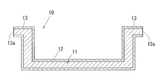
- FIG. 1 is a longitudinal sectional view of a pulp mold container according to a first embodiment of the present invention.
- a pulp mold container 10 is composed of a bottom part and a side wall part rising from the bottom part, and a container body 11 made of a non-wood material obtained from straw and sugar cane, and a synthetic resin layer 12. And a flange portion 13.
- the synthetic resin layer 12 is formed on the entire inner and outer surfaces of the container body 11 except for the outer side end portion 13a of the flange portion 13. If comprised in this way, when the storage thing which has water
- the resin used in the synthetic resin layer 12 is not particularly limited.
- acrylic, styrene-acrylic, ethylene-vinyl acetate, styrene-butadiene rubber, polyvinyl alcohol, vinylidene chloride, wax, fluorine examples thereof include silicone resins, copolymers thereof, and combinations thereof.
- a synthetic resin emulsion or a water-soluble resin that can use an aqueous solvent is preferable.
- the synthetic resin layer 12 is not formed on the outer side end portion 13 a of the flange portion 13 of the pulp mold container 10.
- the pulp mold container 10 when the pulp mold container 10 is sealed by the flange portion 13 with a sealant film, if a blister is generated in the flange portion 13 during heating in the microwave oven, the top seal is opened unintentionally, and leakage of contents or As a result, hands may be burned, but in the pulp mold container 10 of the present invention, the outer side end 13a of the flange portion 13 is not coated with synthetic resin (hereinafter, synthetic resin layer uncoated portion 13a). The occurrence of blisters in the flange portion 13 can be suppressed.
- the ratio of the synthetic resin layer uncoated part 13a to the surface area of the flange part 13 is 1% or more and 10% or less.
- the penetration of moisture such as food into the container body 11 can be sufficiently suppressed and the generation of paper dust can be suppressed.
- the occurrence of blisters and appearance defects can be suppressed in a well-balanced manner.
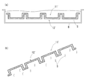
- FIG. 2 schematically shows a method for manufacturing the pulp mold container 10 according to the first embodiment of the present invention.
- a step of preparing a container body connecting body 11 ′ having a connecting portion to which container bodies made of at least two or more pulp molds are connected is performed.
- the connection manner of the container body is not particularly limited as long as it is plural, but there are a total of 8 pieces in which 4 pieces are connected in a row, 4 rows in the horizontal direction, and 2 rows in the vertical direction.
- This container main body connecting body 11 ' can be prepared by a step of forming a known pulp mold.
- a pulp suspension preparation step for preparing a pulp suspension for preparing a pulp suspension
- a papermaking step for making pulp from a pulp suspension in a net shape for making pulp from a pulp suspension in a net shape
- a papermaking product obtained by the papermaking step A container body connecting body constituted by a pulp mold by a first press mold provided at a lower part of the mesh mold while being heated and a second press mold positioned in a direction opposite to the first press mold
- the container body connecting body 11 ′ includes a bottom portion made of a plurality of pulp molds and a side wall portion rising from the bottom portion, and further includes a substantially planar flange portion at an upper end portion of the side wall portion. And the flange part of each adjacent container main body is in the state connected integrally, This part is comprised as a connection part, As a result, each container main body is connected by the connection part.
- the synthetic resin layer 12 ' is formed on both the inside and outside of the container body connecting body 11'.
- the application method is not particularly limited, and examples thereof include a spray method, a brush coating method, and a dipping method.
- the container main body connecting body 11 ′ having the synthetic resin layer 12 ′ formed thereon is appropriately treated by a cutter C or the like at an intermediate portion of the connecting part connecting adjacent pulp mold containers. Cut with. Thereby, it isolate
- the outer edge portions of the flanges at both ends of the container body connecting body 11 ′ are also cut using appropriate means such as the cutter C.
- each pulp mold container 10 has at least one cut surface in the flange portion 13, and the cut surface becomes a synthetic resin layer uncoated portion 13 a in which the synthetic resin layer 12 is not formed.
- FIG. 3 schematically shows another method for manufacturing the pulp mold container 10 according to the first embodiment of the present invention.
- the process which prepares the container main body 11 which consists of a pulp mold first is performed.
- the container body 11 can be prepared roughly by the following two methods. (1) A method in which a container body connecting body having a connecting portion to which a container main body made of at least two or more of the above-described pulp molds connected by a known method is connected is cut at the connecting portion and separated into individual container main bodies. (2) A method of molding a container body made of a pulp mold by a known method. In any of the methods (1) and (2), a conventionally known method can be adopted as a method of molding with a pulp mold.
- a process of forming a synthetic resin layer 12 by applying a synthetic resin to the inner surface and the outer surface of the container body 11 is performed.
- a known method can be adopted as a method of forming the synthetic resin layer.
- the process of forming this synthetic resin layer 12 forms the synthetic resin layer uncoated part 13a in the area
- the process of carrying out is further provided.
- the step of forming the synthetic resin layer uncoated portion is performed, for example, on at least a part of the inner surface and the outer surface of the container body before forming the synthetic resin layer (here, the outer side end portion of the flange portion 13).
- the synthetic resin layer is formed by performing the masking M by the masking means, the synthetic resin layer can be prevented from being formed at the portion where the masking M is applied.
- the portion where the masking M is applied becomes a synthetic resin layer uncoated portion.
- the portion where the masking M is removed (here, the outer side end of the flange portion 13) is the synthetic resin.
- the pulp mold container 10 of the first embodiment is obtained.
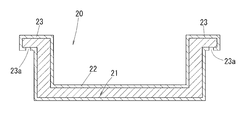
- FIG. 4 is a sectional view showing a pulp mold container according to a second embodiment of the present invention.
- the pulp mold container 20 is comprised from the non-wood raw material comprised from the bottom part and the side wall part which stands
- a container body 21 made of a pulp mold to be formed, a synthetic resin layer 22 and a flange portion 23 are provided.
- the synthetic resin layer 22 is formed on the entire inner and outer surfaces of the container main body 21 except for the removed portion 23 a which is a part of the lower surface side of the flange portion 23.
- the removed portion 23 a functions as the synthetic resin layer uncoated portion 23 a of the pulp mold container 20.
- water vapor generated during heating by the microwave is discharged from the synthetic resin layer uncoated portion 23a, so that the blister is added to the pulp mold container 20 by the microwave heating. Can be prevented from occurring.
- FIG. 5 shows the outline of the manufacturing method of the pulp mold container 20 by 2nd Embodiment of this invention.
- the process which prepares the container main body 21 which consists of a pulp mold first is performed.
- the container body 21 may be separated into individual container bodies by cutting the container body connecting body, or the container body may be molded alone.
- a process of forming a synthetic resin layer 22 by applying a synthetic resin to the inner surface and the outer surface of the container body 21 is performed.
- a method for forming the synthetic resin layer the same method as described above can be adopted.
- the process of forming this synthetic resin layer 22 is a synthetic resin to at least one part area
- the method further includes a step of forming the layer uncoated portion 23a.
- the step of forming the synthetic resin layer uncoated portion is performed by, for example, removing the synthetic resin layer in at least a part of the inner surface and outer surface of the container main body (here, a part on the lower surface side of the flange portion 23) with the laser marker L.
- Example 1 A container body connecting body comprising a bottom part and a side wall part rising from the bottom part and having a plurality of container bodies made of a pulp mold provided with a substantially flat flange part at the upper end of the side wall part was prepared.
- the adjacent container main body is shape
- the size of each container body is as follows.
- Container body 20cm wide (including flange) x 15cm long (including flange) x 5cm in height
- Flange width 1.5cm (including connecting part)
- Cross section thickness of the container body about 1 mm container body
- a synthetic resin layer was formed on the inner and outer surfaces of the container body connecting body.
- the synthetic resin layer was applied by a dipping method so that the entire container body connecting body 11 ′ was dipped in a coating solution tank B containing the synthetic resin solution S and pulled up.
- the excess adhesion of the synthetic resin solution S to the container body connecting body 11 ' is inclined to an appropriate angle when the container body connecting body 11' is pulled up from the coating solution tank B. Removed.
- the product name Cybinol EK-61 (Styrene / acrylic copolymer (acrylic resin component 55 mass%, styrene resin component 45 mass%), solid content concentration 40 mass%) manufactured by Seiden Chemical Co., Ltd. as a synthetic resin.
- the synthetic resin layer was formed so that the coating thickness after drying was about 60 ⁇ m.
- the container main body connection body in which the synthetic resin layer was formed was separated into individual pulp mold containers by cutting at the central portion (connection portion) where the flange portions of the individual container main bodies were connected.
- the synthetic resin layer was not formed on the outer side end of the flange portion, which was a portion cut at the connecting portion.
- the pulp mold container of Example 1 of the present invention was obtained through the above steps.
- Example 2 A container body connecting body in which a plurality of container bodies made of the same pulp mold as in Example 1 are connected was prepared. Unlike Example 1, before forming a synthetic resin layer in a container main body connection body, it cut
- the synthetic resin layer was applied by dipping so that the entire container body was immersed in a coating solution tank containing a synthetic resin solution, and a pulp mold container having a synthetic resin layer formed on the inner and outer surfaces was obtained. .
- the coating film thickness after drying of the synthetic resin solution and the synthetic resin layer was the same as that of Example 1.
- the masking tape was removed from the pulp mold container.
- the pulp mold container after the removal was provided with a synthetic resin layer uncoated portion.
- the pulp mold container of Example 2 of the present invention was obtained through the above steps.
- Example 3 A container body connecting body in which a plurality of container bodies made of the same pulp mold as in Example 1 are connected was prepared. Unlike Example 1, before forming a synthetic resin layer in a container main body connection body, it cut
- Example 1 A container body connecting body in which a plurality of container bodies made of the same pulp mold as in Example 1 are connected was prepared. Unlike Example 1, before forming a synthetic resin layer in a container main body connection body, the container main body was prepared by cut
- Example 1 the coating film thickness after drying of the synthetic resin solution and the synthetic resin layer was the same as that of Example 1.
- a pulp mold container of Comparative Example 1 was obtained in which a synthetic resin layer was formed on the entire surface of the container body and had no synthetic resin layer uncoated portion.
- a sealant film (product name: ABF-65C, product name: ABF-65C, film thickness: 30 ⁇ m, manufactured by Mitsui Chemicals, Inc.) ) was cut into a size of 20 cm wide x 15 cm long and sealed with a top seal in a state of completely covering the flange portion of the pulp mold container. Thereafter, the sealed pulp mold container was stored in a freezer and frozen until the water became completely ice. The frozen pulp mold container was taken out and heated for 5 minutes and 20 seconds at an output of 600 W in a microwave oven (manufactured by Toshiba, model number: ER-C7).
- the pulp mold container was observed after heating, and evaluated as “ ⁇ ” when no blisters or appearance defects occurred in the flange portion, and “X” when blisters or appearance defects occurred.
- the results are shown in Table 1. From Table 1, it was found that any of the pulp mold containers of Examples 1 to 3 can suppress the occurrence of blisters and appearance defects when heated by a microwave oven or the like.
- the synthetic resin layer uncoated portion is provided in the flange portion, but the present invention is not limited to this, and the synthetic resin layer uncoated portion can be provided on the side wall portion other than the flange portion or on the bottom portion.
- the method for forming the synthetic resin layer uncoated portion is not limited to the embodiment. For example, without using masking, only a part of the outer surface of the container main body is synthesized using appropriate means such as spraying or brushing. It is also possible to form a resin layer and make the remaining part a synthetic resin layer uncoated part.
- the container body is composed of a bottom part and a side wall part to which a flange part is attached, but the shape of the container main body is not limited to this, the flange part may not be provided, and the bottom part and the side wall part. It is also possible to use a curved surface that cannot be clearly defined.
- the storage space of the container body is not limited to a single one, and may be divided into a plurality of partitions by a partition or the like.
- the planar view shape of the container body is not particularly limited, and examples thereof include a circle, an ellipse, and a polygon.
Landscapes
- Engineering & Computer Science (AREA)
- Mechanical Engineering (AREA)
- Ceramic Engineering (AREA)
- Life Sciences & Earth Sciences (AREA)
- Food Science & Technology (AREA)
- Chemical & Material Sciences (AREA)
- Chemical Kinetics & Catalysis (AREA)
- Manufacturing & Machinery (AREA)
- Containers Having Bodies Formed In One Piece (AREA)
- Wrappers (AREA)
- Laminated Bodies (AREA)
Abstract
内面と外面のいずれにも合成樹脂層が形成されたパルプモールド容器において、電子レンジ加熱後のブリスターの発生を抑えることができ、外観も良好なパルプモールド容器を簡便な方法にて提供する。パルプモールド容器(10)において、容器本体(11)の一部の領域に合成樹脂層未塗工部(13a)を設けたのである。電子レンジなどによる加熱時に合成樹脂層未塗工部(13a)から容器本体(11)に含まれた水分が蒸発するため、合成樹脂層(12)が形成された部分のブリスターや外観不良を簡単に抑制することができる。
Description
この発明はパルプモールド容器及びパルプモールド容器の製造方法に関し、特に内面および外面に合成樹脂の塗工により形成された合成樹脂層を備えたパルプモールド容器及びその製造方法に関するものである。
食品などを収納する容器として、合成樹脂材料を成型したプラスチック容器や、板紙からなるブランクを折り曲げて接着剤で貼り合わせた紙容器が知られている。
これらは、軽量かつ安価で使い捨てできることから汎用されているが、プラスチック容器は燃焼ごみとして廃棄することができず、また紙容器は内容物の熱により接着がはがれてしまう欠点を有する。
これらは、軽量かつ安価で使い捨てできることから汎用されているが、プラスチック容器は燃焼ごみとして廃棄することができず、また紙容器は内容物の熱により接着がはがれてしまう欠点を有する。
そこで、葦やサトウキビや木材のようなパルプ材を原料とし、この原料を金型で成型してなるパルプモールド容器も用いられている。
パルプモールド容器は、プラスチック容器とは異なり燃焼ごみとして廃棄可能であり、また紙容器とは異なり全体を一体に成型するものであるため、接着がはがれてしまうような事態も生じない。
パルプモールド容器は、プラスチック容器とは異なり燃焼ごみとして廃棄可能であり、また紙容器とは異なり全体を一体に成型するものであるため、接着がはがれてしまうような事態も生じない。
このようなパルプモールド容器は、プラスチック容器とは異なり耐水性に劣り、また表面が擦れると原料由来の紙粉が発生するおそれがある。このため、食品などの水分が多く含まれた内容物を収納するものについては、下記特許文献1のように、内面に熱可塑性フィルムを積層して耐水層を形成するのが一般的である。
ところで、このようにパルプモールド容器の内面に耐水層を形成する場合には、通常は特許文献1のように、パルプモールド容器を多数の吸引孔が形成された金型にセットし、この金型とその上方に配置されたヒータとの間に熱可塑性フィルムを供給し、ヒータにより加熱された熱可塑性フィルムを金型の吸引孔の吸引力によりパルプモールド容器の内面に向けて吸引し、溶着させる方法による。
ところで、このようにパルプモールド容器の内面に耐水層を形成する場合には、通常は特許文献1のように、パルプモールド容器を多数の吸引孔が形成された金型にセットし、この金型とその上方に配置されたヒータとの間に熱可塑性フィルムを供給し、ヒータにより加熱された熱可塑性フィルムを金型の吸引孔の吸引力によりパルプモールド容器の内面に向けて吸引し、溶着させる方法による。
このような吸引方式は、パルプモールド自体が空気透過性を有することを利用したものであるが、容器の内面に耐水層を形成した時点で、その空気透過性は失われることになる。したがって、さらに耐水性向上や紙粉発生をより抑えるために、容器の外面にも耐水層を形成したい場合には、吸引方式を用いることができない。
パルプモールド容器の外面については、手作業でフィルムを貼り付けるなど他の方式を用いることも可能であるが、手間がかかり製造コストが高くなる。
パルプモールド容器の外面については、手作業でフィルムを貼り付けるなど他の方式を用いることも可能であるが、手間がかかり製造コストが高くなる。
一方で、パルプモールド容器の内外面にフィルムを貼り付ける代わりに合成樹脂をパルプモールド容器の内外面に塗布する技術もある。この技術によればパルプモールド容器の内外面に一度に合成樹脂による被膜を形成することが可能である。
しかし、合成樹脂を塗布する前のパルプモールド容器に製法由来の水分が多く残存していることがあり、この場合、パルプモールド容器の内外面に合成樹脂を塗布し固化後、パルプモールド容器に食品を収容して電子レンジによる加熱を行ったときに、加熱中にパルプモールド容器内部の水分が蒸発することでパルプモールド容器と合成樹脂被膜との間に水蒸気による気泡(いわゆるブリスター)が発生してパルプモールド容器の外観が悪くなる。
また、合成樹脂を塗布する前のパルプモールド容器を十分に水分を乾燥した場合であっても、パルプモールド容器の内外面に合成樹脂を塗布する際に合成樹脂エマルジョンなどの水系溶媒で構成される合成樹脂溶液を塗布したときには合成樹脂溶液中に含まれる水分が容器本体内部に浸透してしまう。
したがって、この状態で合成樹脂が固化するとパルプモールド容器内に水分が多く残存しているため、パルプモールド容器に食品を収容して電子レンジによる加熱を行ったときに、先の場合と同様に加熱中にパルプモールド容器内部の水分が蒸発することでパルプモールド容器と合成樹脂被膜との間に水蒸気によるブリスターが発生してパルプモールド容器の外観が悪くなる。
また、合成樹脂を塗布する前のパルプモールド容器を十分に水分を乾燥した場合であっても、パルプモールド容器の内外面に合成樹脂を塗布する際に合成樹脂エマルジョンなどの水系溶媒で構成される合成樹脂溶液を塗布したときには合成樹脂溶液中に含まれる水分が容器本体内部に浸透してしまう。
したがって、この状態で合成樹脂が固化するとパルプモールド容器内に水分が多く残存しているため、パルプモールド容器に食品を収容して電子レンジによる加熱を行ったときに、先の場合と同様に加熱中にパルプモールド容器内部の水分が蒸発することでパルプモールド容器と合成樹脂被膜との間に水蒸気によるブリスターが発生してパルプモールド容器の外観が悪くなる。
さらに、パルプモールド容器に食品を収容する際には食品を密封するためにパルプモールド容器の側壁上方に設けられたフランジ部にシーラントフィルムによりトップシールを行っている場合、電子レンジ加熱によりパルプモールド容器のフランジ部にブリスターが発生すると意図せぬ状態でトップシールが開放状態となり、内容物の漏れやそれに伴い手を火傷するおそれもある。
このようなブリスターの発生を防止する技術として、下記特許文献2のようにパルプモールド容器の外面に形成された塗布層の透湿度と内面に形成された塗布層の透湿度に差をつけたものがある。
しかしながら、この場合はパルプモールド容器の内面と外面とで塗布厚みを変える必要があり手間がかかり製造コストも高くなる。
このようなブリスターの発生を防止する技術として、下記特許文献2のようにパルプモールド容器の外面に形成された塗布層の透湿度と内面に形成された塗布層の透湿度に差をつけたものがある。
しかしながら、この場合はパルプモールド容器の内面と外面とで塗布厚みを変える必要があり手間がかかり製造コストも高くなる。
本発明は、上述した課題を解決するためになされたものであり、内面と外面のいずれにも合成樹脂層が形成されたパルプモールド容器において、電子レンジ加熱後のブリスターの発生を抑えることができ、外観も良好なパルプモールド容器を簡便な方法にて提供することを目的とする。
上記の目的を達成するために、発明にかかるパルプモールド容器を、パルプモールドよりなる容器本体と、前記容器本体の内面および外面に合成樹脂の塗工により形成された合成樹脂層を備え、前記容器の内面および外面の少なくとも一部の領域に合成樹脂層未塗工部を備えたものとしたのである。
このように構成すると、パルプモールド容器の合成樹脂層未塗工部から水分が蒸発可能となる。電子レンジなどによる加熱時にパルプモールド容器の合成樹脂層未塗工部から水分が蒸発するため、合成樹脂層が形成された部分のブリスターや外観不良を抑制することができる。
発明にかかるパルプモールド容器において、前記容器本体は少なくとも底部と底部から立ち上がる側壁部とから構成され、前記合成樹脂層未塗工部は側壁部の一部の領域に形成されたものとすることができる。
このように構成すると、得られたパルプモールド容器が内容物を収容するのに適したものとなる。その結果、パルプモールド容器の使用用途が拡がる。
このように構成すると、得られたパルプモールド容器が内容物を収容するのに適したものとなる。その結果、パルプモールド容器の使用用途が拡がる。
発明にかかるパルプモールド容器において、前記側壁部は上方端部に略平面状のフランジ部をさらに備え、前記合成樹脂層未塗工部は該フランジ部の一部の領域に形成されたものとすることができる。
このように構成すると、フランジ部に形成された合成樹脂層未塗工部から水分が蒸発可能となるため、電子レンジなどによる加熱時に合成樹脂層未塗工部からフランジ部の水分を効率的に蒸発させることができる。
このように構成すると、フランジ部に形成された合成樹脂層未塗工部から水分が蒸発可能となるため、電子レンジなどによる加熱時に合成樹脂層未塗工部からフランジ部の水分を効率的に蒸発させることができる。
発明にかかるパルプモールド容器において、前記合成樹脂層未塗工部は、前記フランジ部の外方側端部に形成されたものとすることができる。
このように構成すると、合成樹脂層未塗工部がフランジ部の外方側端部になるので、該外方端部から水分が蒸発可能となり、パルプモールド容器を密封するためにフランジ部へのシーラントフィルムによるトップシールをした場合に、合成樹脂層未塗工部がトップシールに影響を与えることがなく、電子レンジなどによる加熱時にフランジ部の水分を蒸発させることができる。
このように構成すると、合成樹脂層未塗工部がフランジ部の外方側端部になるので、該外方端部から水分が蒸発可能となり、パルプモールド容器を密封するためにフランジ部へのシーラントフィルムによるトップシールをした場合に、合成樹脂層未塗工部がトップシールに影響を与えることがなく、電子レンジなどによる加熱時にフランジ部の水分を蒸発させることができる。
発明にかかるパルプモールド容器において、前記フランジ部の表面積に占める前記合成樹脂層未塗工部の表面積の割合は1%以上10%以下とすることができ、より好ましくは5%以上10%以下である。
このように構成すると、フランジ部の表面積の大部分は合成樹脂層にて被覆されたものとなるため、紙粉の発生を抑えることができる。
このように構成すると、フランジ部の表面積の大部分は合成樹脂層にて被覆されたものとなるため、紙粉の発生を抑えることができる。
発明にかかるパルプモールド容器において、前記容器本体は、少なくとも2以上の容器本体が連接された容器本体連接体から切断されたものであって、少なくとも1つの切断面を有し、該切断面が前記合成樹脂層未塗工部であるものとすることができる。
このように構成すると、電子レンジなどによる加熱時に切断面から水分が蒸発するので、合成樹脂層が形成された部分のブリスターや外観不良を抑制することができる。
このように構成すると、電子レンジなどによる加熱時に切断面から水分が蒸発するので、合成樹脂層が形成された部分のブリスターや外観不良を抑制することができる。
また上記の目的を達成するために、発明にかかるパルプモールド容器の製造方法を、少なくとも2以上のパルプモールドよりなる容器本体を連接する連接部を備えた容器本体連接体を準備する工程と、前記容器本体連接体の内面および外面に、合成樹脂を塗布して、合成樹脂層を形成する工程と、合成樹脂層が形成された容器本体連接体の連接部で容器本体を切断する工程とを備えるものとしたのである。
このように構成すると、各々のパルプモールド容器が少なくとも一箇所の切断面を有するものとなり、その切断面が水分の蒸発可能な合成樹脂層未塗工部となるため、簡便な方法でパルプモールド容器の合成樹脂層が形成された部分のブリスターや外観不良を抑制することができる
このように構成すると、各々のパルプモールド容器が少なくとも一箇所の切断面を有するものとなり、その切断面が水分の蒸発可能な合成樹脂層未塗工部となるため、簡便な方法でパルプモールド容器の合成樹脂層が形成された部分のブリスターや外観不良を抑制することができる
また上記の目的を達成するために、発明にかかるパルプモールド容器の製造方法を、パルプモールド容器の製造方法であって、パルプモールドよりなる容器本体を準備する工程と、前記容器本体の内面および外面に合成樹脂を塗布して合成樹脂層を形成する工程とを備え、合成樹脂層を形成する工程は、容器本体の内面および外面の少なくとも一部の領域にマスキングを施して合成樹脂層未塗工部を形成する工程をさらに備えるものとしたのである。
このように構成すると、パルプモールド容器は内面および外面の少なくとも一部の領域が水分の蒸発可能な合成樹脂層未塗工部となるため、簡便な方法でパルプモールド容器の合成樹脂層が形成された部分のブリスターや外観不良を抑制することができる。
このように構成すると、パルプモールド容器は内面および外面の少なくとも一部の領域が水分の蒸発可能な合成樹脂層未塗工部となるため、簡便な方法でパルプモールド容器の合成樹脂層が形成された部分のブリスターや外観不良を抑制することができる。
また上記の目的を達成するために、発明にかかるパルプモールド容器の製造方法を、パルプモールドよりなる容器本体を準備する工程と、前記容器本体の内面および外面に合成樹脂を塗布して合成樹脂層を形成する工程とを備え、合成樹脂層を形成する工程は、容器本体の内面および外面の少なくとも一部の領域から合成樹脂層を除去する工程をさらに備えるものとしたのである。
このように構成すると、合成樹脂層を除去した部分が水分の蒸発可能な合成樹脂層未塗工部となるため、簡便な方法でパルプモールド容器の合成樹脂層が形成された部分のブリスターや外観不良を抑制することができる。
このように構成すると、合成樹脂層を除去した部分が水分の蒸発可能な合成樹脂層未塗工部となるため、簡便な方法でパルプモールド容器の合成樹脂層が形成された部分のブリスターや外観不良を抑制することができる。
本発明を以上のように構成したので、電子レンジ加熱後のブリスターの発生を抑えることができ、外観も良好なパルプモールド容器を簡便に提供することが可能となった。
以下、図面を参照しつつ本発明の実施形態について説明する。なお、各図面においては、本発明の実施形態が模式的に表現されており、形状、比率、厚み等は、発明の内容を正確に反映したものではない。
図1は、この発明の第1の実施の形態によるパルプモールド容器の縦断面図である。
図1を参照して、パルプモールド容器10は、底部と底部から立ち上がる側壁部とから構成され葦やサトウキビから得られる非木材素材から形成されるパルプモールドよりなる容器本体11と、合成樹脂層12と、フランジ部13とを備える。
図1を参照して、パルプモールド容器10は、底部と底部から立ち上がる側壁部とから構成され葦やサトウキビから得られる非木材素材から形成されるパルプモールドよりなる容器本体11と、合成樹脂層12と、フランジ部13とを備える。
合成樹脂層12は、容器本体11の内外面全体にフランジ部13の外方側端部13aを除いて形成されている。このように構成すると、食品等の水分を有する収容物をパルプモールド容器10に収容したときに、容器本体11に食品等の水分が浸透せず、また容器本体11からの紙粉の発生を抑制することができる。
合成樹脂層12で用いられる樹脂は特に限定されないが、例えば、アクリル系、スチレン-アクリル系、エチレン-酢酸ビニル系、スチレン-ブタジエンラバー系、ポリビニルアルコール系、塩化ビニリデン系、ワックス系、フッ素系、シリコーン系の樹脂、これらの共重合体およびこれらの組み合わせ等が例示できる。なかでも、水系溶媒が使用できる合成樹脂エマルジョンや水溶性樹脂が好ましい。
パルプモールド容器10のフランジ部13の外方側端部13aには、合成樹脂層12が形成されていない。
これにより、パルプモールド容器10を冷凍食品等の食品収容容器としてもちいた場合には、電子レンジで食品収容容器を加熱時に容器本体11内部の水分が外方側端部13aから水蒸気として排出される。このようにして、電子レンジ加熱によりパルプモールド容器10にブリスターが発生することを抑制することができる。特にパルプモールド容器10がシーラントフィルムによりフランジ部13で密封されている場合には、電子レンジ加熱時にフランジ部13にブリスターが発生すると意図せぬ状態でトップシールが開放状態となり、内容物の漏れやそれに伴い手を火傷するおそれもあるが、本発明のパルプモールド容器10ではフランジ部13の外方側端部13aが合成樹脂が塗工されていない部分(以下、合成樹脂層未塗工部13aという)を備えるため、フランジ部13のブリスターの発生を抑制することができる。
これにより、パルプモールド容器10を冷凍食品等の食品収容容器としてもちいた場合には、電子レンジで食品収容容器を加熱時に容器本体11内部の水分が外方側端部13aから水蒸気として排出される。このようにして、電子レンジ加熱によりパルプモールド容器10にブリスターが発生することを抑制することができる。特にパルプモールド容器10がシーラントフィルムによりフランジ部13で密封されている場合には、電子レンジ加熱時にフランジ部13にブリスターが発生すると意図せぬ状態でトップシールが開放状態となり、内容物の漏れやそれに伴い手を火傷するおそれもあるが、本発明のパルプモールド容器10ではフランジ部13の外方側端部13aが合成樹脂が塗工されていない部分(以下、合成樹脂層未塗工部13aという)を備えるため、フランジ部13のブリスターの発生を抑制することができる。
なお、フランジ部13に合成樹脂層未塗工部13aを形成する場合、フランジ部13の表面積に占める合成樹脂層未塗工部13aの割合は1%以上10%以下であることが好ましい。この場合、フランジ部の表面積の大部分は合成樹脂層にて被覆されたものとなるため、食品等の水分の容器本体11への浸透を十分に抑えることができるとともに紙粉の発生を抑えることができる一方で、ブリスターや外観不良の発生もバランスよく抑えることができる。
図2は、この発明の第1の実施の形態によるパルプモールド容器10の製造方法の概略を示すものである。
図2(a)に示すように、まず少なくとも2以上のパルプモールドよりなる容器本体が連接する連接部を備えた容器本体連接体11´を準備する工程を行う。容器本体連接体11´において容器本体の連接の態様は複数である限りにおいて特に限定されないが、一列に4個が連接されたものや、横方向に4列、縦方向に2列の計8個が連接されたものが例示できる。
この容器本体連接体11´は、公知のパルプモールドを成型する工程により準備することができる。例えば、パルプ懸濁液を準備するパルプ懸濁液準備工程と、パルプ懸濁液から網型でパルプを抄き上げる抄き上げ工程と、前記抄き上げ工程により得られた抄き上げ物を加熱しながら前記網型下部に設けられた第1のプレス金型と前記第1のプレス金型とは反対方向に位置する第2のプレス金型とによりパルプモールドで構成される容器本体連接体11´を成型する加熱プレス工程とからなる工程が例示できる。
なお、容器本体連接体11´は複数のパルプモールドよりなる底部と底部から立ち上がる側壁部とからなり、さらに側壁部の上方端部には略平面状のフランジ部を備えたものである。そして、各々の隣り合う容器本体のフランジ部同士が一体に繋がった状態となっており、この部分が連接部として構成され、その結果、各々の容器本体は連接部により連接されている。
図2(a)に示すように、まず少なくとも2以上のパルプモールドよりなる容器本体が連接する連接部を備えた容器本体連接体11´を準備する工程を行う。容器本体連接体11´において容器本体の連接の態様は複数である限りにおいて特に限定されないが、一列に4個が連接されたものや、横方向に4列、縦方向に2列の計8個が連接されたものが例示できる。
この容器本体連接体11´は、公知のパルプモールドを成型する工程により準備することができる。例えば、パルプ懸濁液を準備するパルプ懸濁液準備工程と、パルプ懸濁液から網型でパルプを抄き上げる抄き上げ工程と、前記抄き上げ工程により得られた抄き上げ物を加熱しながら前記網型下部に設けられた第1のプレス金型と前記第1のプレス金型とは反対方向に位置する第2のプレス金型とによりパルプモールドで構成される容器本体連接体11´を成型する加熱プレス工程とからなる工程が例示できる。
なお、容器本体連接体11´は複数のパルプモールドよりなる底部と底部から立ち上がる側壁部とからなり、さらに側壁部の上方端部には略平面状のフランジ部を備えたものである。そして、各々の隣り合う容器本体のフランジ部同士が一体に繋がった状態となっており、この部分が連接部として構成され、その結果、各々の容器本体は連接部により連接されている。
次に、図2(b)に示すように、容器本体連接体11´の内外両面に合成樹脂層12´を塗工する工程を行う。この工程により容器本体連接体11´の内外両面に合成樹脂層12´が形成される。合成樹脂層12´の形成にあたり、塗布方法は特に限定されず、スプレー法、刷毛塗り、ディッピング法などが挙げられる。
次に、図2(c)に示すように、合成樹脂層12´が形成された容器本体連接体11´を、隣り合うパルプモールド容器を連接する連接部の中間部分でカッタC等の適宜手段を用いて切断する。これにより、複数のパルプモールド容器が繋がった状態から一つ一つに分離される。同時に、容器本体連接体11´の両端部のフランジの外縁部もカッタC等の適宜手段を用いて切断する。この工程により、個々のパルプモールド容器10はフランジ部13に少なくとも1つの切断面を有し、該切断面は合成樹脂層12が形成されていない合成樹脂層未塗工部13aとなる。
以上の工程により、本発明の第1の実施の形態によるパルプモールド容器10を得ることができる。
以上の工程により、本発明の第1の実施の形態によるパルプモールド容器10を得ることができる。
また、図3は、この発明の第1の実施の形態によるパルプモールド容器10の他の製造方法の概略を示すものである。
図3(a)に示すように、まずパルプモールドよりなる容器本体11を準備する工程を行う。容器本体11は、大きくは下記の2つの方法にて準備することができる。
(1)公知の方法で成型された上述した少なくとも2以上のパルプモールドよりなる容器本体が連接する連接部を備えた容器本体連接体を連接部で切断して個々の容器本体に分離する方法。
(2)公知の方法でパルプモールドよりなる容器本体を単体で成型する方法。
(1)および(2)のいずれの方法によっても、パルプモールドにより成型する方法は従来公知の方法が採用できる。
図3(a)に示すように、まずパルプモールドよりなる容器本体11を準備する工程を行う。容器本体11は、大きくは下記の2つの方法にて準備することができる。
(1)公知の方法で成型された上述した少なくとも2以上のパルプモールドよりなる容器本体が連接する連接部を備えた容器本体連接体を連接部で切断して個々の容器本体に分離する方法。
(2)公知の方法でパルプモールドよりなる容器本体を単体で成型する方法。
(1)および(2)のいずれの方法によっても、パルプモールドにより成型する方法は従来公知の方法が採用できる。
次いで、図3(b)から図3(c)に示すように、前記容器本体11の内面および外面に合成樹脂を塗布して合成樹脂層12を形成する工程を行う。合成樹脂層を形成する方法は、公知の方法が採用できる。
そして、この合成樹脂層12を形成する工程は、容器本体の内面および外面の少なくとも一部の領域(ここでは、フランジ部13の外方側端部)に合成樹脂層未塗工部13aを形成する工程をさらに備える。
合成樹脂層未塗工部を形成する工程は、例えば、合成樹脂層を形成する前の容器本体の内面および外面の少なくとも一部の領域(ここでは、フランジ部13の外方側端部)にマスキング手段にてマスキングMを行うことで合成樹脂層を形成した際にマスキングMが施されている箇所には合成樹脂層が形成されないようにすることができる。このマスキングMを施した箇所が合成樹脂層未塗工部となる。
そして、この合成樹脂層12を形成する工程は、容器本体の内面および外面の少なくとも一部の領域(ここでは、フランジ部13の外方側端部)に合成樹脂層未塗工部13aを形成する工程をさらに備える。
合成樹脂層未塗工部を形成する工程は、例えば、合成樹脂層を形成する前の容器本体の内面および外面の少なくとも一部の領域(ここでは、フランジ部13の外方側端部)にマスキング手段にてマスキングMを行うことで合成樹脂層を形成した際にマスキングMが施されている箇所には合成樹脂層が形成されないようにすることができる。このマスキングMを施した箇所が合成樹脂層未塗工部となる。
図3(d)に示すように、合成樹脂層が形成された後にマスキングMを除去することで、マスキングMが除去された箇所(ここでは、フランジ部13の外方側端部)が合成樹脂層未塗工部13aとなり、その結果、第1の実施形態のパルプモールド容器10が得られる。
図4はこの発明の第2の実施の形態によるパルプモールド容器を示す断面図である。
図4を参照して、パルプモールド容器20は、本発明のパルプモールド容器の第1の実施の形態と同様に底部と底部から立ち上がる側壁部とから構成され葦やサトウキビから得られる非木材素材から形成されるパルプモールドよりなる容器本体21と、合成樹脂層22と、フランジ部23とを備える。
図4を参照して、パルプモールド容器20は、本発明のパルプモールド容器の第1の実施の形態と同様に底部と底部から立ち上がる側壁部とから構成され葦やサトウキビから得られる非木材素材から形成されるパルプモールドよりなる容器本体21と、合成樹脂層22と、フランジ部23とを備える。
合成樹脂層22は、フランジ部23の下面側の一部である除去部分23aを除いて容器本体21の内外面全体に形成されている。この除去部分23aは、パルプモールド容器20の合成樹脂層未塗工部23aとして機能する。
本発明の第1の実施の形態によるパルプモールド容器10と同様に、電子レンジにより加熱時に生じる水蒸気が合成樹脂層未塗工部23aから排出されるので、電子レンジ加熱によりパルプモールド容器20にブリスターが発生することを抑制することができる。特にパルプモールド容器20がシーラントフィルムによりフランジ部23で密封されている場合には、電子レンジ加熱時にフランジ部23にブリスターが発生すると意図せぬ状態でトップシールが開放状態となり、内容物の漏れやそれに伴い手を火傷するおそれもあるが、パルプモールド容器20ではフランジ部23の下面側に合成樹脂層未塗工部23aを備えるため、フランジ部23のブリスターの発生を抑制することができる。
本発明の第1の実施の形態によるパルプモールド容器10と同様に、電子レンジにより加熱時に生じる水蒸気が合成樹脂層未塗工部23aから排出されるので、電子レンジ加熱によりパルプモールド容器20にブリスターが発生することを抑制することができる。特にパルプモールド容器20がシーラントフィルムによりフランジ部23で密封されている場合には、電子レンジ加熱時にフランジ部23にブリスターが発生すると意図せぬ状態でトップシールが開放状態となり、内容物の漏れやそれに伴い手を火傷するおそれもあるが、パルプモールド容器20ではフランジ部23の下面側に合成樹脂層未塗工部23aを備えるため、フランジ部23のブリスターの発生を抑制することができる。
図5は、この発明の第2の実施の形態によるパルプモールド容器20の製造方法の概略を示すものである。
図5(a)に示すように、まずパルプモールドよりなる容器本体21を準備する工程を行う。上述したのと同様に、容器本体21は、容器本体連接体を切断して個々の容器本体に分離してもよいし、容器本体を単体で成型してもよい。
図5(a)に示すように、まずパルプモールドよりなる容器本体21を準備する工程を行う。上述したのと同様に、容器本体21は、容器本体連接体を切断して個々の容器本体に分離してもよいし、容器本体を単体で成型してもよい。
次いで、図5(b)に示すように、前記容器本体21の内面および外面に合成樹脂を塗布して合成樹脂層22を形成する工程を行う。合成樹脂層を形成する方法は、上述したのと同様の方法が採用できる。
そして、この合成樹脂層22を形成する工程は、図5(c)のように、容器本体の内面および外面の少なくとも一部の領域(ここではフランジ部23の下面側の一部)に合成樹脂層未塗工部23aを形成する工程をさらに備える。
合成樹脂層未塗工部を形成する工程は、例えば、レーザーマーカーLにより容器本体の内面および外面の少なくとも一部の領域(ここではフランジ部23の下面側の一部)の合成樹脂層を除去することによる。
そして、この合成樹脂層22を形成する工程は、図5(c)のように、容器本体の内面および外面の少なくとも一部の領域(ここではフランジ部23の下面側の一部)に合成樹脂層未塗工部23aを形成する工程をさらに備える。
合成樹脂層未塗工部を形成する工程は、例えば、レーザーマーカーLにより容器本体の内面および外面の少なくとも一部の領域(ここではフランジ部23の下面側の一部)の合成樹脂層を除去することによる。
以下、実施例および比較例を示して、本発明の内容を一層明確にする。
下記のようにして実施例および比較例であるパルプモールド容器をそれぞれ作製した。
下記のようにして実施例および比較例であるパルプモールド容器をそれぞれ作製した。
(実施例1)
底部と底部から立ち上がる側壁部からなり、側壁部上方端部に全周に渡って略平面状のフランジ部を備えたパルプモールドからなる容器本体が複数連接された容器本体連接体を準備した。なお、隣り合う容器本体は各々のフランジ部が繋がった状態で成型されたものである。
ここで個々の容器本体の大きさは以下の通りである。
容器本体:横20cm(フランジ部含む)×縦15cm(フランジ部含む)×高さ5cm
容器本体収容部:横17.5cm×縦12.5cm×高さ5cm
フランジ部の幅:1.5cm(連接部含む)
容器本体の断面厚み:約1mmの容器本体
底部と底部から立ち上がる側壁部からなり、側壁部上方端部に全周に渡って略平面状のフランジ部を備えたパルプモールドからなる容器本体が複数連接された容器本体連接体を準備した。なお、隣り合う容器本体は各々のフランジ部が繋がった状態で成型されたものである。
ここで個々の容器本体の大きさは以下の通りである。
容器本体:横20cm(フランジ部含む)×縦15cm(フランジ部含む)×高さ5cm
容器本体収容部:横17.5cm×縦12.5cm×高さ5cm
フランジ部の幅:1.5cm(連接部含む)
容器本体の断面厚み:約1mmの容器本体
次に、前記容器本体連接体の内面および外面に合成樹脂層を形成した。
合成樹脂層の塗布は、図6(a)のように、合成樹脂溶液Sを含む塗布溶液槽Bに容器本体連接体全体11´を浸漬して引き上げるようにしてディッピング法で塗布した。図6(b)のように、合成樹脂溶液Sの容器本体連接体11´に対する余剰付着分は、容器本体連接体11´を塗布溶液槽Bから引き上げた際に、適宜角度にまで傾けることより除去した。
合成樹脂溶液としては、合成樹脂としてサイデン化学社製の商品名サイビノールEK-61(スチレン・アクリル共重合体(アクリル樹脂成分55質量%、スチレン樹脂成分45質量%)、固形分濃度40質量%)を水で希釈したものを用いた。合成樹脂層は乾燥後の塗膜厚みが約60μmとなるように形成した。
合成樹脂層の塗布は、図6(a)のように、合成樹脂溶液Sを含む塗布溶液槽Bに容器本体連接体全体11´を浸漬して引き上げるようにしてディッピング法で塗布した。図6(b)のように、合成樹脂溶液Sの容器本体連接体11´に対する余剰付着分は、容器本体連接体11´を塗布溶液槽Bから引き上げた際に、適宜角度にまで傾けることより除去した。
合成樹脂溶液としては、合成樹脂としてサイデン化学社製の商品名サイビノールEK-61(スチレン・アクリル共重合体(アクリル樹脂成分55質量%、スチレン樹脂成分45質量%)、固形分濃度40質量%)を水で希釈したものを用いた。合成樹脂層は乾燥後の塗膜厚みが約60μmとなるように形成した。
その後、合成樹脂層を形成した容器本体連接体を個々の容器本体のフランジ部同士が連接している中央部(連接部)で切断することで一つ一つのパルプモールド容器に分離した。分離されたパルプモールド容器は、連接部で切断した箇所であるフランジ部の外方側端部には合成樹脂層が形成されていなかった。
以上の工程を経て、本発明の実施例1のパルプモールド容器を得た。
以上の工程を経て、本発明の実施例1のパルプモールド容器を得た。
(実施例2)
実施例1と同様のパルプモールドからなる容器本体が複数連接された容器本体連接体を準備した。
実施例1とは異なり、容器本体連接体に合成樹脂層を形成する前に容器本体連接体の連接部で切断することで一つ一つの容器本体に分離して容器本体を準備した。
次に、幅1cmの市販のマスキングテープを容器本体のフランジ部外方側端部に幅方向の中心線をもってフランジ部の全周に上下に折り返すように貼り付けた後、容器本体の内面および外面に合成樹脂層を形成した。
合成樹脂層の塗布は、合成樹脂溶液を含む塗布溶液槽に容器本体全体を浸漬して引き上げるようにしてディッピング法で塗布することで内外面に合成樹脂層が形成されたパルプモールド容器を得た。なお、合成樹脂溶液および合成樹脂層の乾燥後の塗膜厚みは実施例1と同様であった。
その後、パルプモールド容器からマスキングテープを除去した。除去後のパルプモールド容器は合成樹脂層未塗工部を備えていた。
以上の工程を経て、本発明の実施例2のパルプモールド容器を得た。
実施例1と同様のパルプモールドからなる容器本体が複数連接された容器本体連接体を準備した。
実施例1とは異なり、容器本体連接体に合成樹脂層を形成する前に容器本体連接体の連接部で切断することで一つ一つの容器本体に分離して容器本体を準備した。
次に、幅1cmの市販のマスキングテープを容器本体のフランジ部外方側端部に幅方向の中心線をもってフランジ部の全周に上下に折り返すように貼り付けた後、容器本体の内面および外面に合成樹脂層を形成した。
合成樹脂層の塗布は、合成樹脂溶液を含む塗布溶液槽に容器本体全体を浸漬して引き上げるようにしてディッピング法で塗布することで内外面に合成樹脂層が形成されたパルプモールド容器を得た。なお、合成樹脂溶液および合成樹脂層の乾燥後の塗膜厚みは実施例1と同様であった。
その後、パルプモールド容器からマスキングテープを除去した。除去後のパルプモールド容器は合成樹脂層未塗工部を備えていた。
以上の工程を経て、本発明の実施例2のパルプモールド容器を得た。
(実施例3)
実施例1と同様のパルプモールドからなる容器本体が複数連接された容器本体連接体を準備した。実施例1とは異なり、容器本体連接体に合成樹脂層を形成する前に容器本体連接体の連接部で切断することで一つ一つの容器本体に分離して容器本体を準備した。
次に、容器本体の内面および外面に合成樹脂層を形成した。
合成樹脂層の塗布は、合成樹脂溶液を含む塗布溶液槽に容器本体全体を浸漬して引き上げるようにしてディッピング法で塗布することで内外面に合成樹脂層が形成されたパルプモールド容器を得た。なお、合成樹脂溶液および合成樹脂層の乾燥後の塗膜厚みは実施例1と同様であった。
その後、パルプモールド容器のフランジ部の下方面の一部分に市販のレーザーマーカー機を用いて合成樹脂層を除去した。レーザーマーカー機による除去後のパルプモールド容器フランジ部の下方面の一部分には合成樹脂層未塗工部が形成されていた。
以上の工程を経て、本発明の実施例3のパルプモールド容器を得た。
実施例1と同様のパルプモールドからなる容器本体が複数連接された容器本体連接体を準備した。実施例1とは異なり、容器本体連接体に合成樹脂層を形成する前に容器本体連接体の連接部で切断することで一つ一つの容器本体に分離して容器本体を準備した。
次に、容器本体の内面および外面に合成樹脂層を形成した。
合成樹脂層の塗布は、合成樹脂溶液を含む塗布溶液槽に容器本体全体を浸漬して引き上げるようにしてディッピング法で塗布することで内外面に合成樹脂層が形成されたパルプモールド容器を得た。なお、合成樹脂溶液および合成樹脂層の乾燥後の塗膜厚みは実施例1と同様であった。
その後、パルプモールド容器のフランジ部の下方面の一部分に市販のレーザーマーカー機を用いて合成樹脂層を除去した。レーザーマーカー機による除去後のパルプモールド容器フランジ部の下方面の一部分には合成樹脂層未塗工部が形成されていた。
以上の工程を経て、本発明の実施例3のパルプモールド容器を得た。
(比較例1)
実施例1と同様のパルプモールドからなる容器本体が複数連接された容器本体連接体を準備した。実施例1とは異なり、容器本体連接体に合成樹脂層を形成する前に容器本体連接体の連接部で切断することで一つ一つの容器本体に分離することで、容器本体を準備した。
次に、容器本体の内面および外面に合成樹脂層を形成した。
合成樹脂層の塗布は、合成樹脂溶液を含む塗布溶液槽に容器本体全体を浸漬して引き上げるようにしてディッピング法で塗布することで内外面に合成樹脂層が形成されたパルプモールド容器を得た。なお、合成樹脂溶液および合成樹脂層の乾燥後の塗膜厚みは実施例1と同様であった。
以上の工程を経て、容器本体の全面に合成樹脂層が形成されて合成樹脂層未塗工部を有しない比較例1のパルプモールド容器を得た。
実施例1と同様のパルプモールドからなる容器本体が複数連接された容器本体連接体を準備した。実施例1とは異なり、容器本体連接体に合成樹脂層を形成する前に容器本体連接体の連接部で切断することで一つ一つの容器本体に分離することで、容器本体を準備した。
次に、容器本体の内面および外面に合成樹脂層を形成した。
合成樹脂層の塗布は、合成樹脂溶液を含む塗布溶液槽に容器本体全体を浸漬して引き上げるようにしてディッピング法で塗布することで内外面に合成樹脂層が形成されたパルプモールド容器を得た。なお、合成樹脂溶液および合成樹脂層の乾燥後の塗膜厚みは実施例1と同様であった。
以上の工程を経て、容器本体の全面に合成樹脂層が形成されて合成樹脂層未塗工部を有しない比較例1のパルプモールド容器を得た。
実施例1から実施例3および比較例1のパルプモールド容器に収容可能体積の70%の水を入れた後、シーラントフィルム(三井化学東セロ株式会社製、製品名:ABF-65C、フィルム厚み:30μm)を横20cm×縦15cmの大きさにカットして、パルプモールド容器のフランジ部を完全に覆う状態でトップシールをして密封した。その後、密封したパルプモールド容器を冷凍庫にて保管し、水が完全に氷になるまで冷凍した。
冷凍後のパルプモールド容器を取り出し、それぞれ、電子レンジ(東芝社製、型番:ER-C7)にて、出力600Wで5分20秒間加熱を行った。
加熱後にパルプモールド容器を観察し、フランジ部にブリスターや外観不良が発生していない場合は「○」、ブリスターや外観不良が発生していた場合は「×」と評価した。その結果を表1に示す。
表1から、実施例1~3のパルプモールド容器はいずれも、電子レンジなどによる加熱時にブリスターの発生や外観不良の発生を抑制することができることがわかった。
冷凍後のパルプモールド容器を取り出し、それぞれ、電子レンジ(東芝社製、型番:ER-C7)にて、出力600Wで5分20秒間加熱を行った。
加熱後にパルプモールド容器を観察し、フランジ部にブリスターや外観不良が発生していない場合は「○」、ブリスターや外観不良が発生していた場合は「×」と評価した。その結果を表1に示す。
表1から、実施例1~3のパルプモールド容器はいずれも、電子レンジなどによる加熱時にブリスターの発生や外観不良の発生を抑制することができることがわかった。

今回開示された実施形態および実施例はすべての点で例示であって制限的なものではないと考慮されるべきである。本発明の範囲は特許請求の範囲によって示され、その範囲内でのすべての修正と変形を含むものであることが意図される。
たとえば実施形態では、合成樹脂層未塗工部をフランジ部に設けているが、これに限定されず、フランジ部以外の側壁部に設けることも、底部に設けることも可能である。
また合成樹脂層未塗工部の形成方法については、実施形態に限定されず、たとえば、マスキングを用いることなく、容器本体の外面の一部にのみスプレー、刷毛塗り等の適宜手段を用いて合成樹脂層を形成し、その余の部分については合成樹脂層未塗工部とすることも可能である。
実施形態では、容器本体を、底部と、フランジ部が付属する側壁部とからなるものとしているが、容器本体の形状はこれに限定されず、フランジ部がなくともよいし、底部と側壁部とを明確に区画することができない、曲面状のものとすることも可能である。容器本体の収納空間は単一のものに限られず、仕切り等により複数に区画されていてもよい。容器本体の平面視形状も特に限定されず、円形、楕円形、多角形などが例示できる。
また合成樹脂層未塗工部の形成方法については、実施形態に限定されず、たとえば、マスキングを用いることなく、容器本体の外面の一部にのみスプレー、刷毛塗り等の適宜手段を用いて合成樹脂層を形成し、その余の部分については合成樹脂層未塗工部とすることも可能である。
実施形態では、容器本体を、底部と、フランジ部が付属する側壁部とからなるものとしているが、容器本体の形状はこれに限定されず、フランジ部がなくともよいし、底部と側壁部とを明確に区画することができない、曲面状のものとすることも可能である。容器本体の収納空間は単一のものに限られず、仕切り等により複数に区画されていてもよい。容器本体の平面視形状も特に限定されず、円形、楕円形、多角形などが例示できる。
10 第1の実施形態のパルプモールド容器
11 容器本体
12 合成樹脂層
13 フランジ部
13a フランジ部の外方側端部(合成樹脂層未塗工部)
20 第2の実施形態のパルプモールド容器
21 容器本体
22 合成樹脂層
23 フランジ部
23a 除去部分(合成樹脂層未塗工部)
11´ 容器本体連接体
12´ 合成樹脂層
C カッタ
M マスキング
L レーザーマーカー
S 合成樹脂溶液
B 塗布溶液槽
11 容器本体
12 合成樹脂層
13 フランジ部
13a フランジ部の外方側端部(合成樹脂層未塗工部)
20 第2の実施形態のパルプモールド容器
21 容器本体
22 合成樹脂層
23 フランジ部
23a 除去部分(合成樹脂層未塗工部)
11´ 容器本体連接体
12´ 合成樹脂層
C カッタ
M マスキング
L レーザーマーカー
S 合成樹脂溶液
B 塗布溶液槽
Claims (9)
- パルプモールド容器であって、
パルプモールドよりなる容器本体と、
前記容器本体の内面および外面に合成樹脂の塗工により形成された合成樹脂層を備え、
前記容器の内面および外面の少なくとも一部の領域に合成樹脂層未塗工部を備えた、パルプモールド容器。 - 前記容器本体は少なくとも底部と底部から立ち上がる側壁部とから構成され、前記合成樹脂層未塗工部は側壁部の一部の領域に形成された、請求項1に記載のパルプモールド容器。
- 前記側壁部は上方端部に略平面状のフランジ部をさらに備え、前記合成樹脂層未塗工部は該フランジ部の一部の領域に形成された、請求項2に記載のパルプモールド容器。
- 前記合成樹脂層未塗工部は、前記フランジ部の外方側端部に形成された、請求項3に記載のパルプモールド容器。
- 前記フランジ部の表面積に占める前記合成樹脂層未塗工部の表面積の割合が1%以上10%以下である、請求項4に記載のパルプモールド容器。
- 前記容器本体は、少なくとも2以上の容器本体が連接された容器本体連接体から切断されたものであって、少なくとも1つの切断面を有し、該切断面が前記合成樹脂層未塗工部である、請求項1から5のいずれかに記載のパルプモールド容器。
- パルプモールド容器の製造方法であって、
少なくとも2以上のパルプモールドよりなる容器本体を連接する連接部を備えた容器本体連接体を準備する工程と、
前記容器本体連接体の内面および外面に、合成樹脂を塗布して、合成樹脂層を形成する工程と、
合成樹脂層が形成された容器本体連接体の連接部で容器本体を切断する工程とを備えた、パルプモールド容器の製造方法。 - パルプモールド容器の製造方法であって、
パルプモールドよりなる容器本体を準備する工程と、
前記容器本体の内面および外面に合成樹脂を塗布して合成樹脂層を形成する工程とを備え、
合成樹脂層を形成する工程は、容器本体の内面および外面の少なくとも一部の領域にマスキングを施して合成樹脂層未塗工部を形成する工程をさらに備えた、パルプモールド容器の製造方法。 - パルプモールド容器の製造方法であって、
パルプモールドよりなる容器本体を準備する工程と、
前記容器本体の内面および外面に合成樹脂を塗布して合成樹脂層を形成する工程とを備え、
合成樹脂層を形成する工程は、容器本体の内面および外面の少なくとも一部の領域から合成樹脂層を除去する工程をさらに備えた、パルプモールド容器の製造方法。
Priority Applications (3)
| Application Number | Priority Date | Filing Date | Title |
|---|---|---|---|
| CN201780061526.2A CN109803899B (zh) | 2016-10-06 | 2017-09-29 | 纸浆模塑容器以及纸浆模塑容器的制造方法 |
| PCT/JP2017/035508 WO2018066475A1 (ja) | 2016-10-06 | 2017-09-29 | パルプモールド容器及びパルプモールド容器の製造方法 |
| EP17858313.4A EP3524537B1 (en) | 2016-10-06 | 2017-09-29 | Molded pulp container and manufacturing method for molded pulp container |
Applications Claiming Priority (3)
| Application Number | Priority Date | Filing Date | Title |
|---|---|---|---|
| JP2016-198055 | 2016-10-06 | ||
| JP2016198055A JP6869686B2 (ja) | 2016-10-06 | 2016-10-06 | パルプモールド容器及びパルプモールド容器の製造方法 |
| PCT/JP2017/035508 WO2018066475A1 (ja) | 2016-10-06 | 2017-09-29 | パルプモールド容器及びパルプモールド容器の製造方法 |
Publications (1)
| Publication Number | Publication Date |
|---|---|
| WO2018066475A1 true WO2018066475A1 (ja) | 2018-04-12 |
Family
ID=61830971
Family Applications (1)
| Application Number | Title | Priority Date | Filing Date |
|---|---|---|---|
| PCT/JP2017/035508 Ceased WO2018066475A1 (ja) | 2016-10-06 | 2017-09-29 | パルプモールド容器及びパルプモールド容器の製造方法 |
Country Status (4)
| Country | Link |
|---|---|
| EP (1) | EP3524537B1 (ja) |
| JP (1) | JP6869686B2 (ja) |
| CN (1) | CN109803899B (ja) |
| WO (1) | WO2018066475A1 (ja) |
Cited By (1)
| Publication number | Priority date | Publication date | Assignee | Title |
|---|---|---|---|---|
| GB2626753A (en) * | 2023-01-31 | 2024-08-07 | Hewlett Packard Development Co | Molded fiber packaging |
Families Citing this family (3)
| Publication number | Priority date | Publication date | Assignee | Title |
|---|---|---|---|---|
| DE102018221674A1 (de) * | 2018-12-13 | 2020-06-18 | Henkel Ag & Co. Kgaa | Vorrichtung und Verfahren zur Herstellung einer wasserlöslichen Hülle sowie diese wasserlösliche Hülle enthaltene Wasch- oder Reinigungsmittelportionen |
| WO2021003324A1 (en) * | 2019-07-03 | 2021-01-07 | Lgab Llc | Pulp container with fused junction and method of making same |
| CN115012254B (zh) * | 2022-05-07 | 2024-09-20 | 吴萤 | 一种纸器制作方法和纸器 |
Citations (5)
| Publication number | Priority date | Publication date | Assignee | Title |
|---|---|---|---|---|
| JPH11334715A (ja) * | 1998-05-25 | 1999-12-07 | Japan Pulp & Paper Co Ltd | 紙製の容器 |
| JP2001114247A (ja) | 1999-10-15 | 2001-04-24 | Kao Corp | 複合容器 |
| JP2002225841A (ja) * | 2001-01-31 | 2002-08-14 | Toppan Printing Co Ltd | 耐水性紙製容器およびその製造方法 |
| JP2012158160A (ja) | 2011-02-03 | 2012-08-23 | Toyo Aluminum Ekco Products Kk | パルプモールド容器及びパルプモールド容器の製造方法 |
| JP2014139299A (ja) * | 2012-12-21 | 2014-07-31 | Nitto Denko Corp | 粘着テープ |
Family Cites Families (15)
| Publication number | Priority date | Publication date | Assignee | Title |
|---|---|---|---|---|
| US4349124A (en) * | 1980-09-22 | 1982-09-14 | Champion International Corporation | Composite paperboard tray |
| DE4308684A1 (de) * | 1993-03-18 | 1994-09-22 | Dietrich Sylvia | Lebensmittelverpackung, Verfahren zur Herstellung einer sauerstoffdichten Verpackung, Vorrichtung zur Durchführung eines derartigen Verfahrens und dabei verwendete Schalenreihe |
| JPH0920372A (ja) * | 1995-07-06 | 1997-01-21 | New Oji Paper Co Ltd | 耐熱性の食品用容器 |
| FI101990B1 (fi) * | 1996-11-22 | 1998-09-30 | Enso Oy | Kuumennettava elintarvikevuoka ja sen valmistusmenetelmä |
| US5916615A (en) * | 1997-06-18 | 1999-06-29 | W. R. Grace & Co.-Conn. | Case-ready packages having smooth, gas-permeable substrates on the bottoms thereof to reduce or prevent discoloration when placed in a stack |
| JPH11171238A (ja) * | 1997-12-10 | 1999-06-29 | Tomen Corp | 食品容器及びその製造方法 |
| JP2001039429A (ja) * | 1999-04-01 | 2001-02-13 | Kao Corp | パルプモールド容器の製造方法 |
| JP2000309322A (ja) * | 1999-04-27 | 2000-11-07 | Oji Paper Co Ltd | 耐水性パルプモウルド容器 |
| CN2415052Y (zh) * | 1999-12-13 | 2001-01-17 | 周大成 | 全自动微波纸浆模塑成型机 |
| JP2002002655A (ja) * | 2000-06-20 | 2002-01-09 | Dainippon Printing Co Ltd | パルプモールドトレーおよびその製造方法 |
| KR101061043B1 (ko) * | 2008-11-05 | 2011-09-01 | (주) 미래이피 | 생분해성 용기 및 그 제조방법 |
| CN102991063B (zh) * | 2012-12-24 | 2015-04-22 | 北京印刷学院 | 一种纸浆模塑制品与塑料的复合材料及制备方法 |
| JP6250287B2 (ja) * | 2013-01-30 | 2017-12-20 | 東洋アルミエコープロダクツ株式会社 | パルプモールド成型体 |
| CN203700877U (zh) * | 2013-10-17 | 2014-07-09 | 江峰 | 基于实心凸缘口体的纸浆容器及其制造模具 |
| US20160236822A1 (en) * | 2015-02-12 | 2016-08-18 | Hsin-Hung Chou | Pulp molded container with double-sided coating |
-
2016
- 2016-10-06 JP JP2016198055A patent/JP6869686B2/ja active Active
-
2017
- 2017-09-29 CN CN201780061526.2A patent/CN109803899B/zh active Active
- 2017-09-29 EP EP17858313.4A patent/EP3524537B1/en active Active
- 2017-09-29 WO PCT/JP2017/035508 patent/WO2018066475A1/ja not_active Ceased
Patent Citations (5)
| Publication number | Priority date | Publication date | Assignee | Title |
|---|---|---|---|---|
| JPH11334715A (ja) * | 1998-05-25 | 1999-12-07 | Japan Pulp & Paper Co Ltd | 紙製の容器 |
| JP2001114247A (ja) | 1999-10-15 | 2001-04-24 | Kao Corp | 複合容器 |
| JP2002225841A (ja) * | 2001-01-31 | 2002-08-14 | Toppan Printing Co Ltd | 耐水性紙製容器およびその製造方法 |
| JP2012158160A (ja) | 2011-02-03 | 2012-08-23 | Toyo Aluminum Ekco Products Kk | パルプモールド容器及びパルプモールド容器の製造方法 |
| JP2014139299A (ja) * | 2012-12-21 | 2014-07-31 | Nitto Denko Corp | 粘着テープ |
Non-Patent Citations (1)
| Title |
|---|
| See also references of EP3524537A4 |
Cited By (1)
| Publication number | Priority date | Publication date | Assignee | Title |
|---|---|---|---|---|
| GB2626753A (en) * | 2023-01-31 | 2024-08-07 | Hewlett Packard Development Co | Molded fiber packaging |
Also Published As
| Publication number | Publication date |
|---|---|
| JP6869686B2 (ja) | 2021-05-12 |
| EP3524537A1 (en) | 2019-08-14 |
| CN109803899B (zh) | 2021-06-15 |
| JP2018058619A (ja) | 2018-04-12 |
| CN109803899A (zh) | 2019-05-24 |
| EP3524537B1 (en) | 2024-08-28 |
| EP3524537A4 (en) | 2020-07-22 |
Similar Documents
| Publication | Publication Date | Title |
|---|---|---|
| JP6869686B2 (ja) | パルプモールド容器及びパルプモールド容器の製造方法 | |
| CA2723849C (en) | Food packaging | |
| JPH0524026B2 (ja) | ||
| HUE033228T2 (hu) | Csomagolástartó és eljárás annak elõállítására | |
| TWI867373B (zh) | 由多層紙構成之成型體的製造方法、由紙構成之成型體及其製造裝置 | |
| JP6349656B2 (ja) | 断熱性容器の製造方法 | |
| JP2019518672A (ja) | 特に乳製品又はチーズ製品用の食品包装、及び関連する製造方法 | |
| FR2937012A1 (fr) | Procede de realisation d'une boite ou d'un habillage d'emballage tronconique ou tronc-pyramidale, notamment pour produits alimentaires ou horticoles, boite et habillage ainsi obtenus | |
| US2101876A (en) | Composite film and method of making | |
| JP5723616B2 (ja) | パルプモールド容器の製造方法 | |
| WO2026083916A1 (ja) | パルプモールド容器 | |
| CN104742635B (zh) | 采用布艺制作立体制品的工艺方法 | |
| EP2800707A1 (en) | Packaging sheet, packaging and associated manufacturing method | |
| JP4052791B2 (ja) | 容器 | |
| FR2835697A1 (fr) | Dispositif d'emballage et de presentation destine aux plants et plantes | |
| CN106142675A (zh) | 隔热纸容器的制造方法 | |
| JP2012240229A (ja) | 環境対応に優れた紙製容器の製造方法 | |
| JP2003054531A (ja) | 食品用容器及びその製法 | |
| JP2020193159A5 (ja) | ||
| IT202200000455A1 (it) | Cestino in materiale cartaceo e procedimento di realizzazione | |
| JP2017159500A (ja) | 環境対応に優れ、且つ作成容易な紙製容器の製造方法 | |
| JP2024170216A (ja) | 紙容器 | |
| US1311595A (en) | Oil-pboof-papeb comtaibteb and pbocess of making | |
| JP6171592B2 (ja) | 吸油機能付き容器 | |
| FR3099756A3 (fr) | Procédés de fabrication d'un récipient ou d'un gobelet avec son couvercle jetable en papier ou carton hydrophobe biosourcés et compostables. |
Legal Events
| Date | Code | Title | Description |
|---|---|---|---|
| 121 | Ep: the epo has been informed by wipo that ep was designated in this application |
Ref document number: 17858313 Country of ref document: EP Kind code of ref document: A1 |
|
| NENP | Non-entry into the national phase |
Ref country code: DE |
|
| ENP | Entry into the national phase |
Ref document number: 2017858313 Country of ref document: EP Effective date: 20190506 |