WO2018066604A1 - ガーメントケース - Google Patents
ガーメントケース Download PDFInfo
- Publication number
- WO2018066604A1 WO2018066604A1 PCT/JP2017/036148 JP2017036148W WO2018066604A1 WO 2018066604 A1 WO2018066604 A1 WO 2018066604A1 JP 2017036148 W JP2017036148 W JP 2017036148W WO 2018066604 A1 WO2018066604 A1 WO 2018066604A1
- Authority
- WO
- WIPO (PCT)
- Prior art keywords
- main body
- clothing
- roll bar
- garment
- garment case
- Prior art date
- Legal status (The legal status is an assumption and is not a legal conclusion. Google has not performed a legal analysis and makes no representation as to the accuracy of the status listed.)
- Ceased
Links
Images











Classifications
-
- A—HUMAN NECESSITIES
- A45—HAND OR TRAVELLING ARTICLES
- A45C—PURSES; LUGGAGE; HAND CARRIED BAGS
- A45C3/00—Flexible luggage; Handbags
- A45C3/004—Foldable garment carrier bags
-
- A—HUMAN NECESSITIES
- A45—HAND OR TRAVELLING ARTICLES
- A45C—PURSES; LUGGAGE; HAND CARRIED BAGS
- A45C13/00—Details; Accessories
- A45C13/02—Interior fittings; Means, e.g. inserts, for holding and packing articles
-
- A—HUMAN NECESSITIES
- A45—HAND OR TRAVELLING ARTICLES
- A45C—PURSES; LUGGAGE; HAND CARRIED BAGS
- A45C13/00—Details; Accessories
- A45C13/02—Interior fittings; Means, e.g. inserts, for holding and packing articles
- A45C13/03—Means for holding garments
-
- B—PERFORMING OPERATIONS; TRANSPORTING
- B65—CONVEYING; PACKING; STORING; HANDLING THIN OR FILAMENTARY MATERIAL
- B65D—CONTAINERS FOR STORAGE OR TRANSPORT OF ARTICLES OR MATERIALS, e.g. BAGS, BARRELS, BOTTLES, BOXES, CANS, CARTONS, CRATES, DRUMS, JARS, TANKS, HOPPERS, FORWARDING CONTAINERS; ACCESSORIES, CLOSURES, OR FITTINGS THEREFOR; PACKAGING ELEMENTS; PACKAGES
- B65D85/00—Containers, packaging elements or packages, specially adapted for particular articles or materials
- B65D85/18—Containers, packaging elements or packages, specially adapted for particular articles or materials for wearing apparel, headwear or footwear
Definitions
- the present invention relates to a garment case for storing clothing.
- the garment case is a bag for storing clothing such as a jacket and pants and carrying the clothing (for example, see Patent Document 1).
- the garment case is folded with the clothing stored. Thereby, a garment case becomes a size which can be carried.
- the garment case is folded with the clothing stored.
- wrinkles due to creases and / or wrinkles due to the shift of the garments may occur in the folded portion of the garment.
- a work for removing the wrinkles is required, which is troublesome for the user. Therefore, a garment case that is unlikely to wrinkle is desired.
- An object of one aspect of the present invention is to provide a garment case that can suppress generation of wrinkles in clothing.
- a garment case is a garment case that stores clothing, and includes a foldable main body that can store garments, and is disposed in a position where the main body can be folded.
- a roll bar extending along the extending direction of the bent portion in a state where the clothing is stored is attached.
- a roll bar is attached to the main body.
- the roll bar is disposed at a position where the main body is bent, and extends along the extending direction of the bent portion in a state where the garment is stored.
- the clothing is folded across the roll bar at the position where the main body is folded.
- the roll bar is attached to the main body, the position does not shift when carrying the garment case. Thereby, it can suppress that a shift
- difference the generation of wrinkles in clothing can be suppressed.
- At least a part of the roll bar may be detachable from the main body. In this configuration, since the roll bar can be removed when the garment is stored in the main body, it is possible to prevent the roll bar from interfering when storing the garment. Therefore, the clothes can be easily stored in the main body.
- it comprises a plate-like first member that can be used when storing tops of clothing, and the first member is covered with the tops so as to be located at a portion including the shoulder part of the tops, It may be placed in the body.
- the shape of the portion including the shoulder portion of the top is held by the first member. Therefore, it is possible to suppress the occurrence of unevenness in clothing due to vibration and / or impact in the main body. As a result, the generation of wrinkles in clothing can be further suppressed.
- the main body is provided with a plate-like second member that can be used when storing bottoms of clothing, and the second member is positioned on the bottoms folded via a roll bar. It may be arranged inside. In this configuration, the bottoms are pressed and held by the second member in the main body. Therefore, it is possible to suppress the occurrence of unevenness in clothing due to vibration and / or impact in the main body. As a result, the generation of wrinkles in clothing can be further suppressed.
- the roll bar includes a bar main body and a support body that supports the bar main body, and the bar main body may have elasticity and flexibility.
- the bar body when the garment is pushed into the roll bar, the bar body is deformed and sinks together with the garment. Thereby, it can suppress that the trace of a bar main body adheres to clothing, As a result, generation
- the bar body of the roll bar has flexibility, so the bar body can follow the bending of the garment case. . Therefore, since clothes are hold
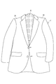
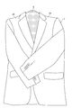
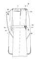
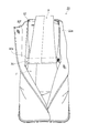
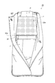
- FIG. 1 (a) and FIG.1 (b) are perspective views which show the garment case which concerns on 1st Embodiment.
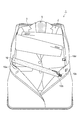
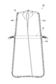
- FIG. 2 is a view showing a state where the garment case shown in FIG. 1 is opened.
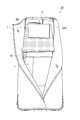
- FIG. 3 is a view showing a state where the lining is opened in the garment case shown in FIG. 2.
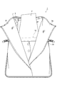
- FIG. 4A is a diagram showing the first member, and
- FIG. 4B is a diagram showing the second member.
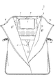
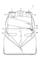
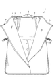
- FIG. 5 is a diagram illustrating a state where clothes are stored in a garment case.
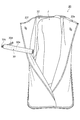
- FIG. 6 is a diagram illustrating an example of a procedure for storing clothes in a garment case.
- FIG. 7 is a diagram illustrating an example of a procedure for storing clothes in a garment case.
- FIG. 1 is a view showing a state where the garment case shown in FIG. 1 is opened.
- FIG. 3 is a view showing a state where the lining is opened in the garment case shown in FIG. 2.
- FIG. 4A is
- FIG. 8 is a diagram illustrating an example of a procedure for storing clothes in a garment case.
- FIG. 9 is a diagram illustrating an example of a procedure for storing clothes in a garment case.
- FIG. 10 is a diagram illustrating an example of a procedure for storing clothes in a garment case.
- FIG. 11 is a diagram illustrating an example of a procedure for storing clothing in a garment case.
- FIG. 12 is a diagram illustrating an example of a procedure for storing clothing in a garment case.
- FIG. 13 is a diagram illustrating an example of a procedure for storing clothing in a garment case.
- FIG. 14 is a diagram illustrating an example of a procedure for storing clothing in a garment case.
- FIG. 14 is a diagram illustrating an example of a procedure for storing clothing in a garment case.
- FIG. 15 is a diagram illustrating an example of a procedure for storing clothes in a garment case.
- FIG. 16 is a diagram illustrating an example of a procedure for storing clothing in a garment case.
- FIG. 17 is a diagram illustrating an example of a procedure for storing clothes in a garment case.
- FIG. 18A and FIG. 18B are perspective views showing a garment case according to the second embodiment.
- FIG. 19 is a view showing a state where the garment case shown in FIG. 18 is opened.
- 20 is a view showing a state where the lining is opened in the garment case shown in FIG.
- FIG. 21A, FIG. 21B, and FIG. 21C are views showing the second member.
- FIG. 22 is a diagram illustrating an example of a procedure for storing clothes in a garment case.
- FIG. 22 is a diagram illustrating an example of a procedure for storing clothes in a garment case.
- FIG. 23 is a diagram illustrating an example of a procedure for storing clothing in a garment case.
- FIG.24 (a) and FIG.24 (b) are figures which show an example of the procedure which accommodates clothing in a garment case.
- FIG. 25 is a diagram illustrating an example of a procedure for storing clothes in a garment case.
- FIG. 26 is a diagram illustrating an example of a procedure for storing clothes in a garment case.
- FIG. 27 is a diagram illustrating an example of a procedure for storing clothing in a garment case.
- FIG. 28 is a diagram illustrating an example of a procedure for storing clothes in a garment case.
- FIG. 29 is a diagram illustrating an example of a procedure for storing clothes in a garment case.
- a garment case 1 shown in FIGS. 1A and 1B stores clothing such as a jacket J (see FIG. 5) and pants P (see FIG. 5).
- the garment case 1 is a portable bag.
- the garment case 1 includes a main body 3, a first member 5, a second member 7, Is provided.
- the garment case 1 has, for example, a width W of 550 mm, a length L of 450 mm, and a height H of 30 mm in the closed state.
- the main body 3 can store clothes and can be folded. As shown in FIGS. 1A and 1B, the main body 3 stores clothing in a folded (closed) state.
- the main body 3 constitutes outer side surfaces 3 a and 3 b of the garment case 1.
- the main body 3 has a substantially rectangular shape in the folded state. As shown in FIG. 2, the main body 3 has a substantially rectangular shape in the opened state.
- the main body 3 is composed of a single member, for example.
- a material of the main body 3 for example, polyester or polyurethane can be used.
- the main body 3 is provided with a town 3c between the outer side surface 3a and the outer side surface 3b (substantially central portion in the longitudinal direction of the main body 3 in FIG. 2).
- the town 3 c extends along the width direction of the main body 3.
- the town 3c is a portion that is folded when the main body 3 is folded.
- the town 3c may be formed of a material having higher rigidity than the main body 3, for example.
- An example of the town 3c is, for example, a polypropylene tape, a bell polen plate, or the like.
- a handle 4 is provided in the town 3c.
- a fastener 3 d is provided on the edge of the main body 3.
- the fastener 3 d is provided so as to surround the four edges of the main body 3.
- the fastener 3d can be opened and closed in a state in which the main body 3 is folded. The state in which the main body 3 is folded is maintained by closing the fastener 3d.
- two linings 3 e and 3 f are provided inside the main body 3.
- the linings 3e and 3f are attached to three inner edges of the main body 3. Specifically, the lining 3 e is attached to one edge along the longitudinal direction of the main body 3 and one edge along the short direction of the main body 3.
- the lining 3 f is attached to the other edge along the longitudinal direction of the main body 3 and one edge along the short side direction of the main body 3. Thereby, the other edge side (upper side in FIG. 3) of the linings 3e and 3f along the short direction of the main body 3 is opened.
- the linings 3e and 3f are fastened to each other in a closed state, for example, by a snap button.
- a roll bar 10 is attached to the main body 3.
- the roll bar 10 is disposed at a position where the main body 3 is bent, and extends along the extending direction of the bent portion in a state where the garment is stored.
- the roll bar 10 is disposed inside the main body 3 at a position corresponding to the town 3c. That is, as shown in FIG. 3, the roll bar 10 is disposed at the center in the length direction of the main body 3 (up and down direction in FIG. 3) when the main body 3 is opened.
- the roll bar 10 extends along the extending direction of the bent portion of the main body 3, that is, the width direction of the main body 3.
- the roll bar 10 is disposed between the inner surface of the main body 3 and the linings 3e and 3f.
- the roll bar 10 includes a bar main body 10a, a support body 10b, a first engagement portion 10c, and a second engagement portion 10d.
- the bar body 10a has a circular outer shape (can include a perfect circle, an ellipse, etc.).
- the outer shape of the bar body 10a is not limited to a circular shape.
- the diameter (outer diameter) of the bar body 10a is, for example, 38 mm.
- the bar body 10a is a hollow member.
- the support 10b is passed through the hollow portion of the bar body 10a.
- the bar body 10a preferably has elasticity and flexibility.
- foamed polyethylene can be used as the material of the bar body 10a.
- the support 10b supports the bar body 10a.
- the support body 10b is a strip-shaped tape.
- polypropylene or the like can be used as the material of the support 10b.
- the support 10b is passed through the hollow portion (inner side) of the bar body 10a.
- One end of the support 10b is fixed to the main body 3. Specifically, one end of the support 10b is fixed to one edge in the width direction (the left edge in FIG. 3) at a substantially central portion in the length direction of the main body 3.
- a first engagement portion 10c is attached to the other end portion of the support 10b.
- the first engaging portion 10c and the second engaging portion 10d constitute a buckle.
- the first engagement portion 10c is attached to the other end portion of the support 10b.
- 10 d of 2nd engaging parts are being fixed to the main body 3 via the tape, for example.
- the second engaging portion 10d is fixed to the other edge (the right edge in FIG. 3) in the width direction at a substantially central portion in the length direction of the main body 3.
- the second engaging portion 10 d is fixed on the same straight line in the width direction of the main body 3 and the position where one end of the support 10 b is fixed to the main body 3.
- the first member 5 is a member that can be used when storing tops of clothing. Examples of the tops include a shirt and a cut-and-sew in addition to the jacket J.
- the first member 5 is a plate material.
- the first member 5 has a shape along the shoulder portions Ja and Jb of the jacket J, as shown in FIG. Specifically, the first member 5 has curved portions 5 a and 5 b provided so as to correspond to the shoulder portions Ja and Jb of the jacket J.
- the first member 5 has, for example, a width W1 (maximum width) of 460 mm and a length L1 of 400 mm. Although the thickness of the 1st member 5 should just be set suitably, it is about 10 mm, for example.
- the first member 5 is made of a material having rigidity and flexibility.
- the first member 5 preferably has a large surface frictional resistance. Examples of the material of the first member 5 include urethane foam.
- the first member 5 can follow the bending or the like of the main body 3 by having rigidity and flexibility. Further, since the frictional resistance of the surface of the first member 5 is large, the clothes are less likely to slip with respect to the first member 5.
- the second member 7 is a member that can be used when storing bottoms of clothing. In addition to the pants P, the bottoms include a skirt and the like.
- the second member 7 is a plate material.
- the second member 7 has a rectangular shape.
- the second member 7 has, for example, a width W2 of 300 mm and a length L2 of 300 mm. Although the thickness of the 2nd member 7 should just be set suitably, it is about 10 mm, for example.
- the second member 7 is formed of a material having rigidity and flexibility.
- the second member 7 preferably has a large surface frictional resistance. Examples of the material of the second member 7 include urethane foam.
- the second member 7 can follow the bending or the like of the main body 3 by having rigidity and flexibility. Further, since the frictional resistance of the surface of the second member 7 is large, the clothes are difficult to slip with respect to the second member 7.
- the first member 5 is disposed on the jacket J.
- the arrangement of the first member 5 on the jacket J may be performed on the main body 3 or may be performed on other than the main body 3.
- the first member 5 is disposed on the jacket J so that the curved portions 5a and 5b of the first member 5 are positioned on the shoulder portions Ja and Jb of the jacket J.
- the jacket J is placed on the main body 3 as shown in FIG. Specifically, the engagement between the first engaging portion 10c and the second engaging portion 10d of the roll bar 10 is released, the roll bar 10 is retracted from the main body 3, and the jacket J is attached to the main body 3. It arrange
- the jacket J is disposed on the main body 3 so that the first member 5 is positioned on the side where the linings 3e and 3f are opened.
- the roll bar 10 is moved onto the jacket J as shown in FIG. 10, and the first engagement portion 10c and the second engagement portion 10d of the roll bar 10 are engaged with each other as shown in FIG. Combine. Thereby, the roll bar 10 is fixed.
- the pants P are arranged between the jacket J and the roll bar 10.
- the pants P may be positioned between the jacket J and the roll bar 10 by placing the pants P on the jacket J before fixing the roll bar 10. That is, the engagement between the first engagement portion 10c and the second engagement portion 10d of the roll bar 10 may be performed after the pants P are disposed on the jacket J.
- the pants P are folded (folded) around the roll bar 10.
- the pants P are folded so that the skirt portion of the pants P protrudes from the upper side of the main body 3 (the side where the linings 3e and 3f are opened).
- the second member 7 is disposed. Specifically, the second member 7 is arranged on the folded pants P. As a result, the second member 7 is disposed at a position overlapping the first member 5.
- the pants P are folded back so that the bottom part of the pants P protruding from the second member 7 is on the second member 7. Thereafter, as shown in FIG. 2, the fasteners 3d are closed after the linings 3e and 3f are closed.
- the jacket J and the pants P are accommodated in the garment case 1 as shown in FIGS. 1 (a) and 1 (b).
- the case in which the first member 5 and the second member 7 are used when both the jacket J and the pants P are stored in the garment case 1 has been described as an example.
- the first member 5 and the second member 7 may be used.
- the second member 7 may be disposed on the jacket J.
- the first member 5 may be disposed under the pants P.
- the clothes are pressed by the first member 5 and the second member 7 arranged in the main body 3. Therefore, it is difficult for the clothes to be displaced. Thereby, it can suppress that wrinkles generate
- the storage form of the pants P is not limited to the above form.
- the second member 7 is arranged on the pants P (position overlapping the first member 5).
- the pants P are folded (folded) around the roll bar 10.
- the pants P are folded so that the skirt portion of the pants P protrudes from the upper side of the main body 3 (the side where the linings 3e and 3f are opened).
- the skirt portion of the pants P is folded back so that the skirt portion of the pants P is disposed between the second member 7 and the pants P.
- the roll bar 10 is attached to the main body 3.
- the roll bar 10 is disposed at a position where the main body 3 is bent, and extends along the extending direction of the bent portion.
- the clothing is folded across the roll bar 10 at a position where the main body 3 is folded.
- the position of the roll bar 10 does not shift when the garment case 1 is carried. Thereby, it can suppress that a shift
- difference can be suppressed. Therefore, in the garment case 1, the generation of wrinkles in clothing can be suppressed.
- the roll bar 10 includes a first engagement portion 10c and a second engagement portion 10d.
- the first engaging portion 10c and the second engaging portion 10d constitute a buckle.
- the first engaging portion 10 c is connected to a support body 10 b that supports the bar main body 10 a, and the second engaging portion 10 d is fixed to the main body 3.
- the roll bar 10 can be attached to and detached from the main body 3 by releasing the engagement between the first engagement portion 10c and the second engagement portion 10d.
- the roll bar 10 can be retracted to a position that does not get in the way, so that the garment can be easily stored in the main body 3.
- the garment case 1 includes a plate-like first member 5 that can be used when storing a jacket J (tops) of clothing.
- the first member 5 is placed in the main body 3 so as to be covered with a top so as to be positioned at a portion including the shoulder portions Ja and Jb of the jacket J.
- the shape of the portion including the shoulder portions Ja and Jb of the jacket J is held by the first member 5. Therefore, it is possible to suppress the occurrence of unevenness in clothing due to vibration and / or impact in the main body 3. As a result, the generation of wrinkles in clothing can be further suppressed.
- the garment case 1 includes a plate-like second member 7 that can be used when storing pants P (bottoms) of clothing.
- the second member 7 is disposed in the main body 3 so as to be positioned on the bottoms folded via the roll bar 10.
- the pants P are pressed and held by the second member 7 in the main body 3. Therefore, it is possible to suppress the occurrence of unevenness in clothing due to vibration and / or impact in the main body 3.
- the generation of wrinkles in clothing can be further suppressed.
- the first member 5 and the second member 7 are disposed so as to overlap each other, so that the clothing is sandwiched between the first member 5 and the second member 7. Therefore, in the garment case 1, the generation of wrinkles in clothing can be further suppressed.
- the roll bar 10 is disposed at a position corresponding to the town 3c where the main body 3 is bent.
- a handle 4 is provided in the town 3c.
- the rigidity of the portion of the town 3 c is secured by cooperation with the roll bar 10. Therefore, when the handle 4 is held and the garment case 1 is held, it is possible to prevent the portion of the town 3c from being bent. As a result, the portability of the garment case 1 can be improved.
- the garment case 20 includes a main body 22, a first member 24, and a second member 7 (see FIG. 4B). As shown in FIGS. 18A and 18B, the garment case 20 is, for example, a width W3 of 360 mm, a length L3 of 480 mm, and a height H3 of 30 mm in the closed state.
- the main body 22 can store clothes and can be folded. As shown in FIG. 18A and FIG. 18B, the main body 22 stores clothing in a folded (closed) state.
- the main body 22 constitutes outer side surfaces 22 a and 22 b of the garment case 20.
- the main body 22 has a substantially rectangular shape in the folded state. As shown in FIG. 19, the main body 22 has a substantially rectangular shape in the opened state.
- the main body 22 is composed of, for example, a single member. As a material of the main body 3, for example, polyester or polyurethane can be used.
- the main body 22 is provided with a town 22c between the outer surface 22a and the outer surface 22b.
- the town 22 c extends along the width direction of the main body 22.
- the town 22c is a portion that is folded when the main body 22 is folded.
- the town 22c is formed of, for example, a material having higher rigidity than the main body 22.
- An example of the town 23c is, for example, a polypropylene tape, a bell polen plate, or the like.
- a handle 23 is provided in the town 22c.
- a fastener 22 d is provided on the edge of the main body 22.
- the fastener 22 d is provided so as to surround the four edges of the main body 22.
- two linings 22 e and 22 f are provided inside the main body 22.
- a roll bar 30 is attached to the main body 22.
- the roll bar 30 is disposed at a position where the main body 22 is bent, and extends along the extending direction of the bent portion in a state in which clothing is stored.
- the configuration of the roll bar 30 is the same as that of the roll bar 10 of the first embodiment.
- the first member 24 is a member that can be used when storing tops of clothing.
- the first member 24 is a plate material.
- the first member 24 includes a first portion 24a, a second portion 24b, and a connecting portion 24c.
- the first portion 24a and the second portion 24b are connected by a connecting portion 24c.
- the first member 24 has a shape along the shoulder portions Ja and Jb of the jacket J.
- the first portion 24 a of the first member 5 has a curved portion 24 d provided so as to correspond to the shoulder portion Ja of the jacket J.
- the second portion 24 b of the first member 5 has a curved portion 24 e provided so as to correspond to the shoulder portion Jb of the jacket J.
- the connecting portion 24c has flexibility.
- the connecting portion 24c is, for example, a strip-shaped tape. With this configuration, as shown in FIG. 21C, the first member 24 can be folded along the vertical direction of the top so that the first portion 24a and the second portion 24b face each other.
- the first member 24 has a width W4 (maximum width) of 475 mm and a length L1 of 370 mm. Although the thickness of the 1st member 24 should just be set suitably, it is about 10 mm, for example. Further, as shown in FIG. 21C, the first member 24 has a width W5 of 230 mm when folded.
- the first member 24 (the first portion 24a and the second portion 24b) is formed of a material having rigidity and flexibility.
- the first member 24 preferably has a large surface frictional resistance. Examples of the material of the first member 24 include, for example, hard urethane.
- the first member 24 can follow the bending or the like of the main body 22 by having rigidity and flexibility.
- the first member 24 is arranged on the jacket J.
- the arrangement of the first member 24 on the jacket J may be performed on the main body 22, or may be performed other than on the main body 22.
- the first member 24 is disposed on the jacket J so that the curved portions 24d and 24e of the first member 24 are positioned on the shoulder portions Ja and Jb of the jacket J.
- the jacket J is folded around the connecting portion 24c of the first member 24 with the button of the jacket J closed and the sleeve positioned on the front side.
- the jacket J is arranged on the main body 22. Specifically, the engagement between the first engagement portion 30c and the second engagement portion 30d of the roll bar 30 is released, the roll bar 30 is retracted from the main body 22, and the jacket J is attached to the main body 22. It arrange
- the roll bar 30 is moved onto the jacket J, and is engaged with the first engagement portion 30c and the second engagement portion 30d of the roll bar 30. Thereby, the roll bar 30 is fixed.
- the pants P are arranged between the jacket J and the roll bar 30.
- the pants P may be positioned between the jacket J and the roll bar 30 by placing the pants P on the jacket J before fixing the roll bar 30. That is, the engagement between the first engagement portion 30c and the second engagement portion 30d of the roll bar 30 may be performed after the pants P are disposed on the jacket J.
- the pants P are folded (folded) around the roll bar 30.
- the pants P are folded so that the skirt portion of the pants P protrudes from the upper side of the main body 22 (the side where the linings 22e and 22f are opened).
- the second member 7 is disposed. Specifically, the second member 7 is arranged on the folded pants P. As a result, the second member 7 is disposed at a position overlapping the first member 24.
- the pants P are folded back so that the bottom part of the pants P protruding from the second member 7 is on the second member 7.
- the fasteners 22d are closed after the linings 22e and 22f are closed.
- the jacket J and the pants P are stored in the garment case 20.
- the case in which the first member 24 and the second member 7 are used when both the jacket J and the pants P are stored in the garment case 1 has been described as an example. Even when only one of the jacket J or the pants P is stored, the first member 24 and the second member 7 may be used as in the first embodiment. Even when one of the clothes is stored, by arranging the first member 24 and the second member 7, the clothes are pressed by the first member 24 and the second member 7 arranged in the main body 22. Therefore, it is difficult for the clothes to be displaced. Thereby, it can suppress that wrinkles generate
- the storage form of the pants P is not limited to the above form.
- the storage form of the pants P may be the form shown in FIGS. 15 to 17 of the first embodiment. That is, after the pants P are arranged on the jacket J, the second member 7 is arranged on the pants P (position overlapping the first member 24). Subsequently, the pants P are folded (folded) around the roll bar 30. At this time, for example, the pants P are folded so that the skirt portion of the pants P protrudes from the upper side of the main body 22 (the side where the linings 22e and 22f open). Subsequently, the skirt portion of the pants P is folded back so that the skirt portion of the pants P is disposed between the second member 7 and the pants P.
- the roll bar 30 is attached to the main body 22.
- the roll bar 30 is disposed at a position where the main body 22 is bent, and extends along the extending direction of the bent portion.
- the clothing is bent with the roll bar 30 in between at the position where the main body 22 is bent.
- the roll bar 30 is attached to the main body 22, the position does not shift when the garment case 20 is carried. Thereby, it can suppress that a shift
- difference can be suppressed. Therefore, in the garment case 20, the generation of wrinkles in clothing can be suppressed.
- the first member 24 can be folded along the vertical direction of the jacket J (tops) by the connecting portion 24c. Thereby, the jacket J can be stored in the main body 22 in a folded state. Thereby, the width
- the main bodies 3, 22, the first members 5, 24, the second member 7, and the roll bars 10, 30 have been described with examples of shapes, dimensions, and materials.
- the shapes, dimensions, and materials of the main bodies 3, 22, the first members 5, 24, the second member 7, and the roll bars 10, 30 can be appropriately set according to the design.
- the dimensions of the main bodies 3 and 22 may be dimensions that can be brought into an airplane, for example.
- the roll bars 10 and 30 have been described as an example in which the roll bars 10 and 30 have the bar main bodies 10a and 30a, the supports 10b and 30b, the first engagement portions 10c and 30c, and the second engagement portions 10d and 30d.
- the configuration of the roll bar is not limited to this.
- the roll bar may be provided with a connecting portion at the center portion.
- the roll bar is configured not to be attached to and detached from the main body, but the roll bar can be connected and disconnected at the central portion. For this reason, when the garment is placed on the main body, the roll bar can be retracted to a position that does not get in the way, so that the garment can be easily stored in the main body.
- the roll bar may be provided so as to be completely detachable from the main body. Further, the roll bar (bar body) may not have a hollow structure.
- the main bodies 3 and 22 are folded in two has been described as an example.
- the main body may be folded three or more.
- the roll bar may be attached so as to extend along the extending direction of the bent portion in a state where the roll bar is disposed at a position where the main body is bent and the garment is stored.
- the means for maintaining the closed state of the main bodies 3 and 22 is not limited to the fastener.
- a snap button or the like may be used as means for maintaining the closed state of the main bodies 3 and 22.
- the garment case may have a form having two or more clothing storage areas (spaces).
- two garment cases 1 shown in the first embodiment may be connected.
- the configuration may be such that the outer side surfaces 3a of the two main bodies 3 are connected back to back.
Landscapes
- Engineering & Computer Science (AREA)
- Mechanical Engineering (AREA)
- Packaging Of Annular Or Rod-Shaped Articles, Wearing Apparel, Cassettes, Or The Like (AREA)
- Purses, Travelling Bags, Baskets, Or Suitcases (AREA)
- Professional, Industrial, Or Sporting Protective Garments (AREA)
- Details Of Garments (AREA)
Abstract
ガーメントケース(1)は、衣類を収納可能であると共に、折り畳み可能な本体(3)を備え、本体(3)内には、当該本体(3)が折り曲げられる位置に配置されると共に衣類が収納された状態において折り曲げ部分の延在方向に沿って延びるロールバー(10)が取り付けられている。
Description
本発明は、衣類を収納するガーメントケースに関する。
ガーメントケースは、ジャケット及びパンツ等の衣類を収納し、当該衣類を持ち運ぶためのかばんである(例えば、特許文献1参照)。ガーメントケースは、衣類を収納した状態で折り畳まれる。これにより、ガーメントケースは、持ち運び可能な大きさとなる。
ガーメントケースは、上述のように、衣類を収納した状態で折り畳まれる。このような構成では、衣類も折り畳まれるため、衣類の折り曲げられた部分に折り目によるシワ、及び/又は、衣類のずれに起因するシワ等が発生するおそれがある。衣類にシワが発生すると、シワを除去するための作業が必要となり、使用者の手間となる。したがって、シワが発生し難いガーメントケースが望まれている。
本発明の一側面は、衣類におけるシワの発生を抑制できるガーメントケースを提供することを目的とする。
本発明の一側面に係るガーメントケースは、衣類を収納するガーメントケースであって、衣類を収納可能であると共に、折り畳み可能な本体を備え、本体内には、当該本体が折り曲げられる位置に配置されると共に衣類が収納された状態において折り曲げ部分の延在方向に沿って延びるロールバーが取り付けられている。
本発明の一側面に係るガーメントケースでは、本体にロールバーが取り付けられている。ロールバーは、本体が折り曲げられる位置に配置されると共に、衣類が収納された状態において折り曲げ部分の延在方向に沿って延びている。この構成では、本体が折り曲げられる位置において、衣類がロールバーを挟んで折り曲げられる。これにより、衣類がロールバーに沿って折り曲げられるため、衣類に折り目が発生し難い。また、ロールバーは、本体に取り付けられるため、ガーメントケースを持ち運ぶときに位置にずれが生じない。これにより、本体内において衣類にずれが生じることを抑制でき、ずれに起因するシワの発生を抑制できる。したがって、ガーメントケースでは、衣類におけるシワの発生を抑制できる。
一実施形態においては、ロールバーは、少なくとも一部が本体に対して着脱可能であってもよい。この構成では、衣類を本体に収納するときに、ロールバーを取り外せるため、ロールバーが衣類を収納するときに邪魔になることを回避できる。したがって、衣類を容易に本体に収納することが可能となる。
一実施形態においては、衣類のうちトップスを収納するときに使用可能である板状の第1部材を備え、第1部材は、トップスの肩部を含む部分に位置するようにトップスが被せられ、本体内に配置されてもよい。この構成では、トップスの肩部を含む部分の形状が第1部材により保持される。したがって、本体内において、振動及び/又は衝撃等により衣類に偏り等が生じることを抑制できる。その結果、衣類におけるシワの発生をより一層抑制できる。
一実施形態においては、衣類のうちボトムスを収納するときに使用可能である板状の第2部材を備え、第2部材は、ロールバーを介して折り畳まれたボトムス上に位置するように、本体内に配置されてもよい。この構成では、本体内において第2部材によりボトムスが押圧されて保持される。したがって、本体内において、振動及び/又は衝撃等により衣類に偏り等が生じることを抑制できる。その結果、衣類におけるシワの発生をより一層抑制できる。
一実施形態においては、ロールバーは、バー本体と、バー本体を支持する支持体と、を有しており、バー本体は、弾性及び柔軟性を有していてもよい。この構成では、衣類がロールバー側に押し込まれた場合、衣類と一緒にバー本体も変形して沈み込む。これにより、衣類にバー本体の跡がつくことを抑制でき、その結果、シワの発生を抑制できる。また、ガーメントケースに外的な力が加えられてガーメントケースが撓んだ場合であっても、ロールバーのバー本体が柔軟性を有しているため、バー本体がガーメントケースの撓みに追従できる。そのため、バー本体によって衣類が保持されるため、本体内において衣類にずれが生じることを抑制できる。したがって、衣類におけるシワの発生を抑制できる。
本発明の一側面によれば、衣類におけるシワの発生を抑制できる。
以下、添付図面を参照して、本発明の好適な実施形態について詳細に説明する。なお、図面の説明において同一又は相当要素には同一符号を付し、重複する説明は省略する。
[第1実施形態]
第1実施形態に係るガーメントケースについて説明する。図1(a)及び図1(b)に示されるガーメントケース1は、ジャケットJ(図5参照)及びパンツP(図5参照)等の衣類を収納する。ガーメントケース1は、持ち運び可能なかばんである。図1(a)、図1(b)、図2、図3及び図4のいずれかに示されるように、ガーメントケース1は、本体3と、第1部材5と、第2部材7と、を備える。図1(a)及び図1(b)に示されるように、ガーメントケース1は、閉じられた状態において、例えば、幅Wが550mm、長さLが450mm、高さHが30mmである。
第1実施形態に係るガーメントケースについて説明する。図1(a)及び図1(b)に示されるガーメントケース1は、ジャケットJ(図5参照)及びパンツP(図5参照)等の衣類を収納する。ガーメントケース1は、持ち運び可能なかばんである。図1(a)、図1(b)、図2、図3及び図4のいずれかに示されるように、ガーメントケース1は、本体3と、第1部材5と、第2部材7と、を備える。図1(a)及び図1(b)に示されるように、ガーメントケース1は、閉じられた状態において、例えば、幅Wが550mm、長さLが450mm、高さHが30mmである。
本体3は、衣類を収納可能であると共に、折り畳み可能である。本体3は、図1(a)及び図1(b)に示されるように、折り畳まれた(閉じられた)状態で、衣類を収納する。本体3は、ガーメントケース1の外側面3a,3bを構成する。本体3は、折り畳まれた状態において、略長方形状を呈している。図2に示されるように、本体3は、開かれた状態において略長方形状を呈している。本体3は、例えば、一枚の部材で構成されている。本体3の材料としては、例えば、ポリエステル、ポリウレタンを用いることができる。
本体3には、外側面3aと外側面3bとの間(図2における本体3の長手方向の略中央部)に、まち3cが設けられている。まち3cは、本体3の幅方向に沿って延在している。まち3cは、本体3が折り畳まれるときに折り曲げられる部分である。まち3cは、例えば、本体3よりも剛性の高い材料で形成されていてもよい。まち3cの一例は、例えば、ポリプロピレン製のテープ、ベルポーレン製の板材等である。まち3cには、取っ手4が設けられている。
図2に示されるように、本体3の縁には、ファスナー3dが設けられている。ファスナー3dは、本体3の4つの縁を囲うように設けられている。図1(a)及び図1(b)に示されるように、ファスナー3dは、本体3が折り畳まれた状態において、開閉することが可能である。ファスナー3dが閉じることで、本体3が折り畳まれた状態が維持される。
図3に示されるように、本体3の内側には、2枚のライニング3e,3fが設けられている。ライニング3e,3fは、本体3の内側の3つの縁に取り付けられている。具体的には、ライニング3eは、本体3の長手方向に沿った一方の縁、及び、本体3の短手方向に沿った一方の縁に取り付けられている。ライニング3fは、本体3の長手方向に沿った他方の縁、及び、本体3の短手方向に沿った一方の縁に取り付けられている。これにより、ライニング3e,3fは、本体3の短手方向に沿った他方の縁側(図3における上側)が開く。図2に示されるように、ライニング3e,3fは、閉じた状態において、例えば、スナップボタンにより互いに留められる。
本体3には、ロールバー10が取り付けられている。ロールバー10は、本体3が折り曲げられる位置に配置されると共に、衣類が収納された状態において折り曲げ部分の延在方向に沿って延びる。具体的には、ロールバー10は、本体3の内側において、まち3cに対応する位置に配置される。すなわち、ロールバー10は、図3に示されるように、本体3が開いた状態において、本体3の長さ方向(図3の上下方向)の中央部に配置される。ロールバー10は、本体3の折り曲げ部分の延在方向、すなわち本体3の幅方向に沿って延びる。ロールバー10は、本体3の内側面とライニング3e,3fとの間に配置される。
本実施形態では、ロールバー10は、バー本体10aと、支持体10bと、第1係合部10cと、第2係合部10dと、を有する。バー本体10aは、外形が円形状(真円、楕円等を含み得る)を呈している。なお、バー本体10aの外形は、円形状に限定されない。バー本体10aの直径(外径)は、例えば、38mmである。本実施形態では、バー本体10aは、中空の部材である。バー本体10aの中空部には、支持体10bが通される。バー本体10aは、弾性及び柔軟性を有していることが好ましい。バー本体10aの材料としては、発泡ポリエチレンを用いることができる。
支持体10bは、バー本体10aを支持する。本実施形態では、支持体10bは、帯状のテープである。支持体10bの材料としては、例えば、ポリプロピレン等を用いることができる。支持体10bは、バー本体10aの中空部(内側)に通されている。支持体10bの一端部は、本体3に固定されている。具体的には、支持体10bの一端部は、本体3の長さ方向の略中央部において、幅方向の一方の縁(図3では左側の縁)側に固定されている。支持体10bの他端部には、第1係合部10cが取り付けられている。
第1係合部10c及び第2係合部10dは、バックルを構成している。第1係合部10cは、支持体10bの他端部に取り付けられている。第2係合部10dは、本体3に例えばテープを介して固定されている。具体的には、第2係合部10dは、本体3の長さ方向の略中央部において、幅方向の他方の縁(図3では右側の縁)側に固定されている。つまり、第2係合部10dは、支持体10bの一端部が本体3に固定されている位置と、本体3の幅方向において同一直線上に固定されている。これにより、第1係合部10cと第2係合部10dとが係合したときに、ロールバー10が本体3の幅方向に延在して位置する。
第1部材5は、衣類のうちトップスを収納するときに使用可能な部材である。トップスとしては、ジャケットJの他に、例えば、シャツ、カットソー等が含まれる。第1部材5は、板材である。第1部材5は、図4(a)に示されるように、ジャケットJの肩部Ja,Jbに沿う形状を呈している。具体的には、第1部材5は、ジャケットJの肩部Ja,Jbに対応するように設けられた湾曲部5a,5bを有している。
第1部材5は、例えば、幅W1(最大幅)が460mm、長さL1が400mmである。第1部材5の厚みは、適宜設定されればよいが、例えば、10mm程度である。第1部材5は、剛性及び柔軟性を有する材料で形成されている。また、第1部材5は、表面の摩擦抵抗が大きいことが好ましい。第1部材5の材料の例としては、例えば、発泡ウレタン等が挙げられる。第1部材5は、剛性及び柔軟性を有することにより、本体3の撓み等に追従できる。また、第1部材5の表面の摩擦抵抗が大きいことにより、衣類が第1部材5に対して滑り難くなる。
第2部材7は、衣類のうちボトムスを収納するときに使用可能な部材である。ボトムスとしては、パンツPの他に、スカート等が含まれる。第2部材7は、板材である。第2部材7は、矩形状を呈している。第2部材7は、例えば、幅W2が300mm、長さL2が300mmである。第2部材7の厚みは、適宜設定されればよいが、例えば、10mm程度である。第2部材7は、剛性及び柔軟性を有する材料で形成されている。また、第2部材7は、表面の摩擦抵抗が大きいことが好ましい。第2部材7の材料の例としては、例えば、発泡ウレタン等が挙げられる。第2部材7は、剛性及び柔軟性を有することにより、本体3の撓み等に追従できる。また、第2部材7の表面の摩擦抵抗が大きいことにより、衣類が第2部材7に対して滑り難くなる。
続いて、上記構成を有するガーメントケース1の使用方法について詳細に説明する。以下の説明では、衣類として、ジャケットJ及びパンツPをガーメントケース1に収納する形態を一例に説明する。
最初に、図6及び図7に示されるように、ジャケットJに第1部材5を配置する。ジャケットJへの第1部材5の配置は、本体3上で行ってもよいし、本体3上以外で行ってもよい。第1部材5は、当該第1部材5の湾曲部5a,5bがジャケットJの肩部Ja,Jbに部が位置するように、ジャケットJに配置する。次に、図8に示されるように、ジャケットJのボタンを閉めると共に袖を前側に位置させた状態で、図9に示されるように、ジャケットJを本体3に配置する。具体的には、ロールバー10の第1係合部10cと第2係合部10dとの係合を解除し、ロールバー10を本体3上から待避させて状態で、ジャケットJを本体3とライニング3e,3fとの間に配置する。ジャケットJは、ライニング3e,3fが開く側に第1部材5が位置するように、本体3に配置する。
続いて、図10に示されるように、ロールバー10をジャケットJ上に移動させて、図11に示されるように、ロールバー10の第1係合部10cと第2係合部10dと係合させる。これにより、ロールバー10が固定される。
次に、図12に示されるように、パンツPをジャケットJとロールバー10との間に配置する。なお、パンツPは、ロールバー10を固定する前に、ジャケットJ上に配置することで、ジャケットJとロールバー10との間に位置させてもよい。すなわち、ロールバー10の第1係合部10cと第2係合部10dとの係合は、パンツPをジャケットJ上に配置した後に行ってもよい。
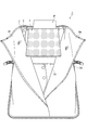
続いて、図13に示されるように、パンツPをロールバー10を中心として折り畳む(折り曲げる)。このとき、例えば、パンツPの裾部分が本体3の上側(ライニング3e,3fが開く側)からはみ出すように、パンツPを折り畳む。続いて、図14に示されるように、第2部材7を配置する。具体的には、折り畳まれたパンツP上に第2部材7を配置する。これにより、第2部材7は、第1部材5と重なる位置に配置される。
そして、図5に示されるように、第2部材7よりも突出するパンツPの裾部分が第2部材7上となるように、パンツPを折り返す。その後、図2に示されるように、ライニング3e,3fを閉じた後にファスナー3dを閉じる。以上により、図1(a)及び図1(b)に示されるように、ジャケットJ及びパンツPがガーメントケース1に収納される。
上記形態では、ジャケットJ及びパンツPの両方をガーメントケース1に収納するにあたり、第1部材5及び第2部材7を用いる形態を一例に説明した。ジャケットJ又はパンツPの一方のみを収納する場合であっても、第1部材5及び第2部材7を用いてもよい。例えば、ジャケットJのみを収納する場合、ジャケットJ上に第2部材7を配置してもよい。また、例えば、パンツPのみを収納する場合、パンツPの下に第1部材5を配置してもよい。いずれか一方の衣類を収納する場合であっても、第1部材5及び第2部材7を配置することにより、衣類が本体3内に配置される第1部材5及び第2部材7に押圧されるため、衣類にずれが生じ難くなる。これにより、衣類においてシワが発生することを抑制できる。
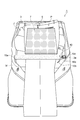
なお、パンツPの収納形態は、上記形態に限定されない。図15に示されるように、パンツPをジャケットJ上に配置した後、パンツP上(第1部材5と重なる位置)に第2部材7を配置する。続いて、図16に示されるように、パンツPをロールバー10を中心として折り畳む(折り曲げる)。このとき、例えば、パンツPの裾部分が本体3の上側(ライニング3e,3fが開く側)からはみ出すように、パンツPを折り畳む。続いて、図17に示されるように、パンツPの裾部分が第2部材7とパンツPとの間に配置されるように、パンツPの裾部分を折り返す。
以上説明したように、本実施形態に係るガーメントケース1では、本体3にロールバー10が取り付けられている。ロールバー10は、本体3が折り曲げられる位置に配置されると共に、折り曲げ部分の延在方向に沿って延びている。この構成では、本体3が折り曲げられる位置において、衣類がロールバー10を挟んで折り曲げられる。これにより、衣類がロールバー10に沿って折り曲げられるため、衣類に折り目が発生し難い。また、ロールバー10は、本体3に取り付けられるため、ガーメントケース1を持ち運ぶときに位置にずれが生じない。これにより、本体3内において衣類にずれが生じることを抑制でき、ずれに起因するシワの発生を抑制できる。したがって、ガーメントケース1では、衣類におけるシワの発生を抑制できる。
本実施形態に係るガーメントケース1では、ロールバー10は、第1係合部10c及び第2係合部10dを有している。第1係合部10c及び第2係合部10dは、バックルを構成している。第1係合部10cは、バー本体10aを支持する支持体10bに接続されており、第2係合部10dは、本体3に固定されている。このような構成により、第1係合部10cと第2係合部10dとの係合を解除することにより、ロールバー10が本体3に対して着脱可能となる。これにより、衣類を本体3に収納するときに、ロールバー10を邪魔にならない位置に待避させることができるため、衣類を容易に本体3に収納することが可能となる。
本実施形態に係るガーメントケース1は、衣類のうちジャケットJ(トップス)を収納するときに使用可能である板状の第1部材5を備える。第1部材5は、ジャケットJの肩部Ja,Jbを含む部分に位置するようにトップスが被せられ、本体3内に配置される。この構成では、ジャケットJの肩部Ja,Jbを含む部分の形状が第1部材5により保持される。したがって、本体3内において、振動及び/又は衝撃等により衣類に偏り等が生じることを抑制できる。その結果、衣類におけるシワの発生をより一層抑制できる。
本実施形態に係るガーメントケース1は、衣類のうちパンツP(ボトムス)を収納するときに使用可能である板状の第2部材7を備える。第2部材7は、ロールバー10を介して折り畳まれたボトムス上に位置するように、本体3内に配置される。この構成では、本体3内において第2部材7によりパンツPが押圧されて保持される。したがって、本体3内において、振動及び/又は衝撃等により衣類に偏り等が生じることを抑制できる。その結果、衣類におけるシワの発生をより一層抑制できる。特に、本実施形態に係るガーメントケース1では、第1部材5と第2部材7とが重ねられて配置されるため、第1部材5及び第2部材7により衣類が挟持される。したがって、ガーメントケース1では、衣類におけるシワの発生をより一層抑制できる。
本実施形態に係るガーメントケース1では、ロールバー10は、本体3が折り曲げられる部分であるまち3cに対応する位置に配置される。ガーメントケース1では、まち3cに取っ手4が設けられている。この構成では、まち3cの部分がロールバー10との協働により、剛性が確保されている。そのため、取っ手4を把持してガーメントケース1を持ったときに、まち3cの部分が撓むことを抑制できる。その結果、ガーメントケース1の携帯性の向上を図れる。
[第2実施形態]
続いて、第2実施形態に係るガーメントケースについて、図18~図23を参照して説明する。各図に示される第2実施形態に係るガーメントケース20は、第1実施形態に係るガーメントケース1よりも小型である。
続いて、第2実施形態に係るガーメントケースについて、図18~図23を参照して説明する。各図に示される第2実施形態に係るガーメントケース20は、第1実施形態に係るガーメントケース1よりも小型である。
上記各図のいずれかに示されるように、ガーメントケース20は、本体22と、第1部材24と、第2部材7(図4(b)参照)と、を備える。図18(a)及び図18(b)に示されるように、ガーメントケース20は、閉じられた状態において、例えば、幅W3が360mm、長さL3が480mm、高さH3が30mmである。
本体22は、衣類を収納可能であると共に、折り畳み可能である。本体22は、図18(a)及び図18(b)に示されるように、折り畳まれた(閉じられた)状態で、衣類を収納する。本体22は、ガーメントケース20の外側面22a,22bを構成する。本体22は、折り畳まれた状態において、略長方形状を呈している。図19に示されるように、本体22は、開かれた状態において略長方形状を呈している。本体22は、例えば、一枚の部材で構成されている。本体3の材料としては、例えば、ポリエステル、ポリウレタンを用いることができる。
本体22には、外側面22aと外側面22bとの間に、まち22cが設けられている。まち22cは、本体22の幅方向に沿って延在している。まち22cは、本体22が折り畳まれるときに折り曲げられる部分である。まち22cは、例えば、本体22よりも剛性の高い材料で形成されている。まち23cの一例は、例えば、ポリプロピレン製のテープ、ベルポーレン製の板材等である。まち22cには、取っ手23が設けられている。
図19に示されるように、本体22の縁には、ファスナー22dが設けられている。ファスナー22dは、本体22の4つの縁を囲うように設けられている。図20に示されるように、本体22の内側には、2枚のライニング22e,22fが設けられている。
図22に示されるように、本体22には、ロールバー30が取り付けられている。ロールバー30は、本体22が折り曲げられる位置に配置されると共に、衣類が収納された状態において折り曲げ部分の延在方向に沿って延びる。ロールバー30の構成は、第1実施形態のロールバー10と同様である。
第1部材24は、衣類のうちトップスを収納する際に使用可能な部材である。第1部材24は、板材である。第1部材24は、図21(a)~図21(b)に示されるように、第1部分24aと、第2部分24bと、連結部分24cと、を有する。第1部分24aと第2部分24bとは、連結部分24cにより連結されている。第1部材24は、ジャケットJの肩部Ja,Jbに沿う形状を呈している。具体的には、第1部材5の第1部分24aは、ジャケットJの肩部Jaに対応するように設けられた湾曲部24dを有している。第1部材5の第2部分24bは、ジャケットJの肩部Jbに対応するように設けられた湾曲部24eを有している。連結部分24cは、可撓性を有する。連結部分24cは、例えば、帯状のテープである。この構成により、第1部材24は、図21(c)に示されるように、第1部分24aと第2部分24bとが対向するように、トップスの上下方向に沿って折り畳み可能である。
第1部材24は、図21(a)に示されるように、例えば、幅W4(最大幅)が475mm、長さL1が370mmである。第1部材24の厚みは、適宜設定されればよいが、例えば、10mm程度である。また、第1部材24は、図21(c)に示されるように、折り畳まれたときの幅W5が230mmである。第1部材24(第1部分24a、第2部分24b)は、剛性及び柔軟性を有する材料で形成されている。また、第1部材24は、表面の摩擦抵抗が大きいことが好ましい。第1部材24の材料の例としては、例えば、硬質ウレタン等が挙げられる。第1部材24は、剛性及び柔軟性を有することにより、本体22の撓み等に追従できる。
続いて、上記構成を有するガーメントケース20の使用方法について詳細に説明する。以下の説明では、衣類として、ジャケットJ及びパンツPを収納する形態を一例に説明する。
最初に、図24(a)に示されるように、ジャケットJに第1部材24を配置する。ジャケットJへの第1部材24の配置は、本体22上で行ってもよいし、本体22上以外で行ってもよい。第1部材24は、当該第1部材24の湾曲部24d,24eがジャケットJの肩部Ja,Jbに部が位置するように、ジャケットJに配置する。次に、図24(b)に示されるように、ジャケットJのボタンを閉めると共に袖を前側に位置させた状態で、ジャケットJを第1部材24の連結部分24cを中心に折り畳む。
続いて、図25に示されるように、ジャケットJを本体22に配置する。具体的には、ロールバー30の第1係合部30cと第2係合部30dとの係合を解除し、ロールバー30を本体22上から待避させて状態で、ジャケットJを本体22とライニング22e,22fとの間に配置する。ジャケットJは、ライニング22e,22fが開く側に第1部材24が位置するように、本体22に配置する。
続いて、図26に示されるように、ロールバー30をジャケットJ上に移動させて、ロールバー30の第1係合部30cと第2係合部30dと係合させる。これにより、ロールバー30が固定される。
次に、図27に示されるように、パンツPをジャケットJとロールバー30との間に配置する。なお、パンツPは、ロールバー30を固定する前に、ジャケットJ上に配置することで、ジャケットJとロールバー30との間に位置させてもよい。すなわち、ロールバー30の第1係合部30cと第2係合部30dとの係合は、パンツPをジャケットJ上に配置した後に行ってもよい。
続いて、図28に示されるように、パンツPをロールバー30を中心として折り畳む(折り曲げる)。このとき、例えば、パンツPの裾部分が本体22の上側(ライニング22e,22fが開く側)からはみ出すように、パンツPを折り畳む。続いて、図29に示されるように、第2部材7を配置する。具体的には、折り畳まれたパンツP上に第2部材7を配置する。これにより、第2部材7は、第1部材24と重なる位置に配置される。
そして、図23に示されるように、第2部材7よりも突出するパンツPの裾部分が第2部材7上となるように、パンツPを折り返す。その後、図19に示されるように、ライニング22e,22fを閉じた後にファスナー22dを閉じる。以上により、図18(a)及び図18(b)に示されるように、ジャケットJ及びパンツPがガーメントケース20に収納される。
上記形態では、ジャケットJ及びパンツPの両方をガーメントケース1に収納するにあたり、第1部材24及び第2部材7を用いる形態を一例に説明した。ジャケットJ又はパンツPの一方のみを収納する場合であっても、第1実施形態と同様に、第1部材24及び第2部材7を用いてもよい。いずれか一方の衣類を収納する場合であっても、第1部材24及び第2部材7を配置することにより、衣類が本体22内に配置される第1部材24及び第2部材7に押圧されるため、衣類にずれが生じ難くなる。これにより、衣類においてシワが発生することを抑制できる。
なお、パンツPの収納形態は、上記形態に限定されない。パンツPの収納形態は、第1実施形態の図15~図17に示す形態であってもよい。すなわち、パンツPをジャケットJ上に配置した後、パンツP上(第1部材24と重なる位置)に第2部材7を配置する。続いて、パンツPをロールバー30を中心として折り畳む(折り曲げる)。このとき、例えば、パンツPの裾部分が本体22の上側(ライニング22e,22fが開く側)からはみ出すように、パンツPを折り畳む。続いて、パンツPの裾部分が第2部材7とパンツPとの間に配置されるように、パンツPの裾部分を折り返す。
以上説明したように、本実施形態に係るガーメントケース20では、本体22にロールバー30が取り付けられている。ロールバー30は、本体22が折り曲げられる位置に配置されると共に、折り曲げ部分の延在方向に沿って延びている。この構成では、本体22が折り曲げられる位置において、衣類がロールバー30を挟んで折り曲げられる。これにより、衣類がロールバー30に沿って折り曲げられるため、衣類に折り目が発生し難い。また、ロールバー30は、本体22に取り付けられるため、ガーメントケース20を持ち運ぶときに位置にずれが生じない。これにより、本体22内において衣類にずれが生じることを抑制でき、ずれに起因するシワの発生を抑制できる。したがって、ガーメントケース20では、衣類におけるシワの発生を抑制できる。
本実施形態に係るガーメントケース20では、第1部材24は、連結部分24cにより、ジャケットJ(トップス)の上下方向に沿って折り畳み可能である。これにより、ジャケットJを折り畳んだ状態で本体22に収納できる。これにより、本体22の幅を小さくすることができる。その結果、ガーメントケース20の小型化を図ることができる。
以上、本発明の実施形態について説明してきたが、本発明は必ずしも上述した実施形態に限定されるものではなく、その要旨を逸脱しない範囲で様々な変更が可能である。
上記実施形態では、本体3,22、第1部材5,24、第2部材7、及び、ロールバー10,30について、形状、寸法及び材料の一例を挙げて説明した。しかし、本体3,22、第1部材5,24、第2部材7、及び、ロールバー10,30の形状、寸法及び材料は、設計に応じて適宜設定できる。本体3,22の寸法としては、例えば、飛行機の機内に持ち込み可能な寸法とすることもできる。
上記実施形態では、ロールバー10,30が、バー本体10a,30a、支持体10b,30b、第1係合部10c,30c及び第2係合部10d,30dを有する形態を一例に説明した。しかし、ロールバーの構成はこれに限定されない。例えば、ロールバーは、中央部分に連結部分が設けられていてもよい。この場合、ロールバーは本体に対して着脱されない構成であるが、ロールバーが中央部分において連結及び連結の解除が可能となる。そのため、衣類を本体に配置するときに、ロールバーを邪魔にならない位置に待避させることができるため、衣類を容易に本体に収納することが可能となる。また、ロールバーは、本体に対して完全に着脱可能に設けられてもよい。また、ロールバー(バー本体)は、中空の構造を有していなくてもよい。
上記実施形態では、本体3,22が2つに折り畳まれる形態を一例に説明した。しかし、本体は、3つ以上折り畳まれる形態であってもよい。この構成の場合、ロールバーが、本体が折り曲げられる位置に配置されると共に衣類が収納された状態において折り曲げ部分の延在方向に沿って延びて取り付けられればよい。
上記実施形態では、本体3,22にファスナー3d,22dが設けられている形態を一例に説明した。しかし、本体3,22が閉じた状態を維持するための手段は、ファスナーに限定されない。例えば、本体3,22が閉じた状態を維持するための手段として、スナップボタン等を用いてもよい。
上記実施形態に加えて、ガーメントケースは、衣類の収納領域(空間)を2以上有する形態であってもよい。具体的には、例えば、第1実施形態に示すガーメントケース1が2個連結されている形態であってもよい。より詳細には、例えば、2つの本体3の外側面3aが背中合わせに連結されたような構成であってもよい。
1,20…ガーメントケース、3,22…本体、5,24…第1部材、7…第2部材、10,30…ロールバー、J…ジャケット(トップス)、P…パンツ(ボトムス)。
Claims (6)
- 衣類を収納するガーメントケースであって、
前記衣類を収納可能であると共に、折り畳み可能な本体を備え、
前記本体内には、当該本体が折り曲げられる位置に配置されると共に前記衣類が収納された状態において折り曲げ部分の延在方向に沿って延びるロールバーが取り付けられている、ガーメントケース。 - 前記ロールバーは、少なくとも一部が前記本体に対して着脱可能である、請求項1に記載のガーメントケース。
- 前記衣類のうちトップスを収納するときに使用可能である板状の第1部材を備え、
前記第1部材は、前記トップスの肩部を含む部分に位置するように前記トップスが被せられ、前記本体内に配置される、請求項1又は2に記載のガーメントケース。 - 前記第1部材は、前記トップスの上下方向に沿って折り畳み可能である、請求項3に記載のガーメントケース。
- 前記衣類のうちボトムスを収納するときに使用可能である板状の第2部材を備え、
前記第2部材は、前記ロールバーを介して折り畳まれた前記ボトムス上に位置するように、前記本体内に配置される、請求項1~4のいずれか一項に記載のガーメントケース。 - 前記ロールバーは、バー本体と、前記バー本体を支持する支持体と、を有しており、
前記バー本体は、弾性及び柔軟性を有する、請求項1~5のいずれか一項に記載のガーメントケース。
Priority Applications (3)
| Application Number | Priority Date | Filing Date | Title |
|---|---|---|---|
| US16/339,369 US20200046092A1 (en) | 2016-10-05 | 2017-10-04 | Garment case |
| CN201780061643.9A CN109788831A (zh) | 2016-10-05 | 2017-10-04 | 服装套 |
| EP17858441.3A EP3524083A4 (en) | 2016-10-05 | 2017-10-04 | CLOTHING COVER |
Applications Claiming Priority (2)
| Application Number | Priority Date | Filing Date | Title |
|---|---|---|---|
| JP2016197330A JP6276822B1 (ja) | 2016-10-05 | 2016-10-05 | ガーメントケース |
| JP2016-197330 | 2016-10-05 |
Publications (1)
| Publication Number | Publication Date |
|---|---|
| WO2018066604A1 true WO2018066604A1 (ja) | 2018-04-12 |
Family
ID=61158444
Family Applications (1)
| Application Number | Title | Priority Date | Filing Date |
|---|---|---|---|
| PCT/JP2017/036148 Ceased WO2018066604A1 (ja) | 2016-10-05 | 2017-10-04 | ガーメントケース |
Country Status (5)
| Country | Link |
|---|---|
| US (1) | US20200046092A1 (ja) |
| EP (1) | EP3524083A4 (ja) |
| JP (1) | JP6276822B1 (ja) |
| CN (1) | CN109788831A (ja) |
| WO (1) | WO2018066604A1 (ja) |
Families Citing this family (2)
| Publication number | Priority date | Publication date | Assignee | Title |
|---|---|---|---|---|
| USD1038620S1 (en) * | 2022-08-08 | 2024-08-13 | Xiamen Lanai Technology Co., Ltd. | Garment bag |
| USD1033051S1 (en) * | 2022-09-07 | 2024-07-02 | Xiamen Lanai Technology Co., Ltd. | Suit bag |
Citations (7)
| Publication number | Priority date | Publication date | Assignee | Title |
|---|---|---|---|---|
| JPS4731631Y1 (ja) * | 1968-04-17 | 1972-09-22 | ||
| JPS509127U (ja) * | 1973-02-20 | 1975-01-30 | ||
| JPS51157405U (ja) * | 1975-06-09 | 1976-12-15 | ||
| JPS5824219A (ja) * | 1981-08-03 | 1983-02-14 | Nec Corp | 可変等化器 |
| US5622255A (en) * | 1993-05-03 | 1997-04-22 | Ricco International | Portfolio-style garment bag |
| US20090101528A1 (en) * | 2007-10-22 | 2009-04-23 | Hl Operating Corp. | Wrinkle reducing garment enclosure |
| JP2012081084A (ja) * | 2010-10-12 | 2012-04-26 | Tokita Keori Kk | 折畳可能な衣類収納具 |
Family Cites Families (16)
| Publication number | Priority date | Publication date | Assignee | Title |
|---|---|---|---|---|
| US1382964A (en) * | 1920-08-13 | 1921-06-28 | Fasel Charles | Suitcase |
| JPS51104805U (ja) * | 1975-02-18 | 1976-08-21 | ||
| JPS51143610U (ja) * | 1975-05-08 | 1976-11-18 | ||
| JPS5425212Y2 (ja) * | 1976-05-08 | 1979-08-23 | ||
| JPS5824219U (ja) * | 1981-08-10 | 1983-02-16 | 株式会社セントラル工業 | 携帯用和服衣装ケ−ス |
| US4679575A (en) * | 1984-11-23 | 1987-07-14 | Japan Tobacco Inc. | Cigarette |
| JPH043994Y2 (ja) * | 1985-10-18 | 1992-02-06 | ||
| JPH023296Y2 (ja) * | 1986-02-04 | 1990-01-25 | ||
| US5425449A (en) * | 1993-08-10 | 1995-06-20 | Boorady; Charles A. | Convertible bag and a method for converting the bag between two functional carrying modes |
| CN1117010A (zh) * | 1994-08-16 | 1996-02-21 | 陈建 | 西服衬板及其包装袋 |
| JPH08268482A (ja) * | 1995-03-29 | 1996-10-15 | Tadashi Matsui | 着物等の折り畳み保管用クッション |
| US6505736B2 (en) * | 2000-12-29 | 2003-01-14 | Brian J. Donovan | Garment storage apparatus and system |
| DE20120463U1 (de) * | 2001-12-18 | 2002-04-25 | Mümtaz, Piri, 81929 München | Faltschablone für Bekleidungsstücke |
| ITMI20080230U1 (it) * | 2008-07-21 | 2010-01-22 | Armeria Meschieri S A S Di Luca Va Lcarenghi & C | Accessorio da viaggio per il ripiegamento di indumenti. |
| CN101485515B (zh) * | 2008-11-11 | 2010-09-29 | 中国人民解放军总后勤部军需装备研究所 | 一种礼服衣帽箱 |
| CN104780804B (zh) * | 2012-11-09 | 2017-05-17 | 套装包装私人有限公司 | 衣服携带器 |
-
2016
- 2016-10-05 JP JP2016197330A patent/JP6276822B1/ja not_active Expired - Fee Related
-
2017
- 2017-10-04 EP EP17858441.3A patent/EP3524083A4/en not_active Withdrawn
- 2017-10-04 WO PCT/JP2017/036148 patent/WO2018066604A1/ja not_active Ceased
- 2017-10-04 US US16/339,369 patent/US20200046092A1/en not_active Abandoned
- 2017-10-04 CN CN201780061643.9A patent/CN109788831A/zh active Pending
Patent Citations (7)
| Publication number | Priority date | Publication date | Assignee | Title |
|---|---|---|---|---|
| JPS4731631Y1 (ja) * | 1968-04-17 | 1972-09-22 | ||
| JPS509127U (ja) * | 1973-02-20 | 1975-01-30 | ||
| JPS51157405U (ja) * | 1975-06-09 | 1976-12-15 | ||
| JPS5824219A (ja) * | 1981-08-03 | 1983-02-14 | Nec Corp | 可変等化器 |
| US5622255A (en) * | 1993-05-03 | 1997-04-22 | Ricco International | Portfolio-style garment bag |
| US20090101528A1 (en) * | 2007-10-22 | 2009-04-23 | Hl Operating Corp. | Wrinkle reducing garment enclosure |
| JP2012081084A (ja) * | 2010-10-12 | 2012-04-26 | Tokita Keori Kk | 折畳可能な衣類収納具 |
Non-Patent Citations (1)
| Title |
|---|
| See also references of EP3524083A4 * |
Also Published As
| Publication number | Publication date |
|---|---|
| JP6276822B1 (ja) | 2018-02-07 |
| EP3524083A1 (en) | 2019-08-14 |
| CN109788831A (zh) | 2019-05-21 |
| EP3524083A4 (en) | 2020-06-03 |
| JP2018057594A (ja) | 2018-04-12 |
| US20200046092A1 (en) | 2020-02-13 |
Similar Documents
| Publication | Publication Date | Title |
|---|---|---|
| US11001406B2 (en) | Foldable box having adhesive wing portions | |
| US9403617B2 (en) | Collapsible containers | |
| CN110792883B (zh) | 折纸式扶手 | |
| KR200472711Y1 (ko) | 포장상자용 손잡이 | |
| JP6276822B1 (ja) | ガーメントケース | |
| US10188184B2 (en) | Folding suitcase | |
| JP3209172U (ja) | 収納箱 | |
| JP2015054174A (ja) | 携帯用ベッド | |
| JP3178252U (ja) | 折曲板体と可撓性フィルムとを組み合わせた緩衝部材 | |
| JP5415064B2 (ja) | 梱包装置および梱包装置の組み立て方法 | |
| JP2008114922A (ja) | 組立て式収納ケース | |
| JP2012125466A (ja) | 平板状携帯端末カバー | |
| JP3224071U (ja) | 二重バッグ | |
| JP2019107363A (ja) | 物品収納ケース | |
| JP3231274U (ja) | バッグ | |
| JP2016218336A (ja) | 展示用パネル | |
| JP3131973U (ja) | 折りたたみ箱 | |
| JP3127205U (ja) | 折り畳み式マットレス | |
| JP2017088224A (ja) | 保冷箱 | |
| JP2022129293A (ja) | 袋体 | |
| JP3214833U (ja) | 袋、及びランドセル | |
| JP3208670U (ja) | 組立式簡易トイレ | |
| JP2016117963A (ja) | 襟ガード支持体 | |
| CN115500594A (zh) | 收纳用具 | |
| JP2020000337A (ja) | バッグ |
Legal Events
| Date | Code | Title | Description |
|---|---|---|---|
| 121 | Ep: the epo has been informed by wipo that ep was designated in this application |
Ref document number: 17858441 Country of ref document: EP Kind code of ref document: A1 |
|
| NENP | Non-entry into the national phase |
Ref country code: DE |
|
| ENP | Entry into the national phase |
Ref document number: 2017858441 Country of ref document: EP Effective date: 20190506 |