WO2018068614A1 - Procédé de détermination de zone de radiomessagerie, nœud de réseau d'accès et nœud de réseau central - Google Patents
Procédé de détermination de zone de radiomessagerie, nœud de réseau d'accès et nœud de réseau central Download PDFInfo
- Publication number
- WO2018068614A1 WO2018068614A1 PCT/CN2017/102375 CN2017102375W WO2018068614A1 WO 2018068614 A1 WO2018068614 A1 WO 2018068614A1 CN 2017102375 W CN2017102375 W CN 2017102375W WO 2018068614 A1 WO2018068614 A1 WO 2018068614A1
- Authority
- WO
- WIPO (PCT)
- Prior art keywords
- terminal
- network node
- paging area
- inactive state
- rrc inactive
- Prior art date
- Legal status (The legal status is an assumption and is not a legal conclusion. Google has not performed a legal analysis and makes no representation as to the accuracy of the status listed.)
- Ceased
Links
Images




Classifications
-
- H—ELECTRICITY
- H04—ELECTRIC COMMUNICATION TECHNIQUE
- H04W—WIRELESS COMMUNICATION NETWORKS
- H04W36/00—Hand-off or reselection arrangements
- H04W36/0005—Control or signalling for completing the hand-off
- H04W36/0055—Transmission or use of information for re-establishing the radio link
-
- H—ELECTRICITY
- H04—ELECTRIC COMMUNICATION TECHNIQUE
- H04W—WIRELESS COMMUNICATION NETWORKS
- H04W68/00—User notification, e.g. alerting and paging, for incoming communication, change of service or the like
- H04W68/02—Arrangements for increasing efficiency of notification or paging channel
-
- H—ELECTRICITY
- H04—ELECTRIC COMMUNICATION TECHNIQUE
- H04W—WIRELESS COMMUNICATION NETWORKS
- H04W36/00—Hand-off or reselection arrangements
- H04W36/08—Reselecting an access point
-
- H—ELECTRICITY
- H04—ELECTRIC COMMUNICATION TECHNIQUE
- H04W—WIRELESS COMMUNICATION NETWORKS
- H04W36/00—Hand-off or reselection arrangements
- H04W36/24—Reselection being triggered by specific parameters
- H04W36/32—Reselection being triggered by specific parameters by location or mobility data, e.g. speed data
-
- H—ELECTRICITY
- H04—ELECTRIC COMMUNICATION TECHNIQUE
- H04W—WIRELESS COMMUNICATION NETWORKS
- H04W68/00—User notification, e.g. alerting and paging, for incoming communication, change of service or the like
- H04W68/005—Transmission of information for alerting of incoming communication
-
- H—ELECTRICITY
- H04—ELECTRIC COMMUNICATION TECHNIQUE
- H04W—WIRELESS COMMUNICATION NETWORKS
- H04W76/00—Connection management
- H04W76/20—Manipulation of established connections
- H04W76/27—Transitions between radio resource control [RRC] states
-
- H—ELECTRICITY
- H04—ELECTRIC COMMUNICATION TECHNIQUE
- H04W—WIRELESS COMMUNICATION NETWORKS
- H04W76/00—Connection management
- H04W76/30—Connection release
-
- H—ELECTRICITY
- H04—ELECTRIC COMMUNICATION TECHNIQUE
- H04W—WIRELESS COMMUNICATION NETWORKS
- H04W8/00—Network data management
- H04W8/02—Processing of mobility data, e.g. registration information at HLR [Home Location Register] or VLR [Visitor Location Register]; Transfer of mobility data, e.g. between HLR, VLR or external networks
- H04W8/08—Mobility data transfer
-
- H—ELECTRICITY
- H04—ELECTRIC COMMUNICATION TECHNIQUE
- H04W—WIRELESS COMMUNICATION NETWORKS
- H04W92/00—Interfaces specially adapted for wireless communication networks
- H04W92/04—Interfaces between hierarchically different network devices
- H04W92/10—Interfaces between hierarchically different network devices between terminal device and access point, i.e. wireless air interface
Definitions
- the present disclosure relates to the field of communications technologies, and in particular, to a method for determining a paging area, an access network node, and a core network node.
- the architecture of the NextGen network is mainly composed of User Equipment (UE, also called terminal), Radio Access Network (RAN) node, and NextGen Core Network. composition.
- the NextGen Core Network is composed of the CP functions and the UP functions.
- the UE is connected to the CP functions through the NG1 interface.
- the RAN node is connected to the CP functions through the NG2 interface and connected to the UP functions through the NG3 interface.
- the CP functions are connected to the UP functions via the NG4 interface, and the CP functions are connected to the application service function (AF) via the NG5 interface, and the UP functions are connected to the data network (DN) via the NG6 interface.
- AF application service function
- DN data network
- RRC radio resource control
- the UE is transparent to the core network in this state, that is, the core network still considers that the UE is always in the connected state, so the downlink signaling or data will arrive at the RAN node, and the RAN node needs to page the UE.
- a method for determining a radio access network level (RAN level) paging area in TR 23.799 is as follows:
- Step 1 The UE carries the area information that the UE expects to stay for a long time in the Service Request message.
- Step 2 The NG Core (Next Generation Core Network) determines an intended area according to the UE's expectation, the UE's subscription, and the network configuration. Then, in the process of using the user plane, the NG Core and the RAN negotiate the UE to allow the RRC_inactive_connected state. Long-term resident area, then The NG Core determines the negotiated area as a Long Connected Allowed Area and notifies the UE;
- Step 3 The UE enters an RRC inactive mode.
- Step 4 When the UE moves out of the Long Connected Allowed Area, the UE notifies the NG Core to update or delete the Long Connected Allowed Area.
- the paging area cannot be updated or re-allocated, thereby affecting the communication of the network.
- the technical problem to be solved by the present disclosure is to provide a method for determining a paging area, an access network node, and a core network node, which are used to solve the problem in the related art that the UE does not move out of the current RAN level paging area.
- an embodiment of the present disclosure provides a method for determining a paging area, which is applied to an access network node, including: acquiring indication information for paging area allocation for a terminal; and determining, for the terminal, the terminal according to the indication information. a paging area; notifying the paging area to the terminal.
- the indication information is: the terminal allows to use the radio resource to control the area information of the RRC inactive state; or the terminal allows the indication of the RRC inactive state to be used.
- the determining, according to the indication information, the paging area for the terminal includes: The indication of the active state determines the paging area based on the cell granularity for the terminal.
- the step of determining, according to the indication information, the paging area for the terminal includes: The terminal allows the terminal to determine a paging area based on the cell granularity in the area information of the RRC inactive state, wherein the determined cell granularity-based paging area is included by the terminal to allow the area in which the RRC inactive state is used.
- the determining, by the terminal, the paging area based on the cell granularity comprises: acquiring network deployment and configuration of the access network node side and mobility characteristic information of the terminal; according to the network Deployment and configuration and mobility characteristic information of the terminal are determined for the terminal A paging area based on cell granularity.
- the step of notifying the paging area to the terminal comprises: transmitting the paging area directly to the terminal by using an air interface message.
- the method for determining a paging area further includes: when the terminal is connected to an access network node again, the access network node re-determines a paging area for the terminal.
- the step of acquiring the indication information for the paging area allocation of the terminal includes: acquiring, when the core network node receives the location update request of the terminal, sending the paging area allocation for the terminal. Instructions.
- the step of notifying the paging area to the terminal comprises: sending the paging area to the core network node, so that the core network node The call area is sent to the terminal; or the paging area is directly sent to the terminal by using an air interface message.
- the step of acquiring the indication information for the paging area allocation by the terminal includes: receiving, after the terminal moves out of the current paging area, the indication information that is sent by the terminal for paging area allocation.
- the step of determining, according to the indication information, whether the terminal can use the RRC inactive state comprises: acquiring, according to the indication information, area information that the terminal is allowed to use the RRC inactive state; The terminal allows the use of the area information of the RRC inactive state to determine whether the terminal can use the RRC inactive state.
- the step of acquiring the area information that the terminal is allowed to use the RRC inactive state according to the indication information includes: sending a request to the first access network node to obtain the allowed use of the terminal.
- the area information of the RRC inactive state ; or sending a request to the core network node to obtain the area information of the terminal that is allowed to use the RRC inactive state.
- the method for determining a paging area further includes: if the terminal cannot use the RRC inactive state, sending an RRC inactive state deactivation message to the core network node, so that the core network node notifies The terminal cannot continue to use the RRC inactive state.
- the method for determining the paging area further includes: sending a path switching request to the core network node And causing the core network node to update the control plane connection and the user plane connection between the access network node and the core network node for the terminal.
- the step of notifying the paging area to the terminal comprises: transmitting the paging area directly to the terminal by using an air interface message.
- An embodiment of the present disclosure provides an access network node, including: a first acquiring module, configured to acquire indication information for paging area allocation for a terminal; and a first determining module, configured to determine, for the terminal, according to the indication information a call area, configured to notify the terminal of the paging area.
- the indication information is:
- the terminal allows to use the radio resource to control the area information of the RRC inactive state; or the terminal allows the indication of the RRC inactive state to be used.
- the first determining module is configured to: determine, based on the indication that the terminal allows to use the RRC inactive state, The paging area of the cell granularity.
- the first determining module is configured to: allow the RRC inactive state to be used in the terminal.
- the area information a paging area based on cell granularity is determined for the terminal, wherein the determined cell granularity-based paging area is included by the terminal to allow the area in which the RRC inactive state is used.
- the determining, by the terminal, the paging area based on the cell granularity is: acquiring network deployment and configuration on the access network node side, and mobility characteristic information of the terminal; according to the network The deployment and configuration and mobility characteristic information of the terminal determine a paging area based on cell granularity for the terminal.
- the notification module is configured to: send the paging area directly to the terminal by using an air interface message.
- the access network node further includes: a second determining module, when the terminal is connected to the access network node again, the access network node re-determines the terminal for the terminal Call area.
- the first obtaining module is configured to: obtain, when the core network node receives the location update request of the terminal, the indication information that is sent by the terminal for paging area allocation.
- the notification module is configured to: send the paging area to the core network node, so that the core network node sends the paging area to the terminal; or The paging area is directly sent to the terminal by an air interface message.
- the first obtaining module is configured to: after the receiving terminal moves out of the current paging area, send the indication information that the terminal performs paging area allocation.
- the first determining module includes: a determining submodule, configured to determine, according to the indication information, whether the terminal can use an RRC inactive state; and the first determining submodule is configured to: if the terminal can When the RRC inactive state is used, the paging area is determined for the terminal.
- the determining sub-module includes: an obtaining unit, configured to acquire, according to the indication information, area information that the terminal is allowed to use an RRC inactive state; and a determining unit, configured to allow, according to the terminal, use The area information of the RRC inactive state determines whether the terminal can use the RRC inactive state.
- the acquiring unit is configured to: send a request to the first access network node to obtain area information of the terminal that is allowed to use an RRC inactive state; or send a request to a core network node, And acquiring area information of the terminal that is allowed to use an RRC inactive state.
- the first determining module further includes: a first sending submodule, configured to send an RRC inactive state deactivation message to the core network node if the terminal is not in the RRC inactive state, The core network node is notified that the terminal cannot continue to use the RRC inactive state.
- a first sending submodule configured to send an RRC inactive state deactivation message to the core network node if the terminal is not in the RRC inactive state, The core network node is notified that the terminal cannot continue to use the RRC inactive state.
- the access network node further includes: a first sending module, configured to send a path switching request to the core network node, so that the core network node updates the access network node for the terminal Control plane connection and user plane connection with core network nodes.
- a first sending module configured to send a path switching request to the core network node, so that the core network node updates the access network node for the terminal Control plane connection and user plane connection with core network nodes.
- the notification module is configured to: send the paging area directly to the terminal by using an air interface message.
- An embodiment of the present disclosure provides a method for determining a paging area, which is applied to a core network node, including: acquiring a location update request of a terminal; determining, according to the location update request, whether the terminal is allowed to use a radio resource to control an RRC inactive state; Allows the use of radio resources to control RRC inactivity, Then, the terminal sends an indication information of the paging area allocation to the access network node.
- the indication information includes: area information provided by the core network node to allow the use of the radio resource to control the RRC inactive state or an indication that the terminal allows to use the RRC inactive state.
- the step of acquiring a location update request of the terminal includes: receiving a location update request sent when the terminal moves out of the current paging area, where the location update request includes the terminal moving out the current paging.
- the location update request includes the terminal moving out the current paging.
- the step of sending the indication information for the paging area allocation of the terminal to the access network node includes: Determining the area information that allows the terminal to use the RRC inactive state; and transmitting the area information as the indication information of the paging area allocation by the terminal to the access network node.
- the method for determining the paging area before the step of determining, according to the location update request, whether the terminal is allowed to use the radio resource to control the RRC inactive state, the method for determining the paging area further includes: determining whether the terminal is An area in which an RRC inactive state is allowed to be used; if the terminal is in an area where the RRC inactive state is allowed to be used, performing a step of determining, according to the location update request, whether the terminal is allowed to use the radio resource to control the RRC inactive state; If the terminal is not in an area where the RRC inactive state is allowed to be used, the terminal returns a response message to notify the terminal that the RRC inactivity state cannot be continued.
- the method for determining a paging area further includes: receiving a paging area fed back by an access network node; and transmitting the paging area to the terminal.
- the embodiment of the present disclosure further provides a core network node, including: a second obtaining module, configured to acquire a location update request of the terminal; and a third determining module, configured to determine, according to the location update request, whether the terminal is allowed to use the radio resource control
- the RRC is inactive state; the second sending module is configured to: if the RRC inactive state is allowed to be used by using the radio resource, send the indication information for the paging area allocation of the terminal to the access network node.
- the indication information includes: area information provided by the core network node to allow the use of the radio resource to control the RRC inactive state or an indication that the terminal allows to use the RRC inactive state.
- the second obtaining module is configured to: receive the terminal to move out of the current When the paging area is sent, the location update request is sent, and the location update request includes indication information that the terminal moves out of the current paging area.
- the second sending module when the indication information includes the area information that the terminal is allowed to use the radio resource to control the RRC inactive state, includes: a second determining submodule, configured to determine that the terminal is allowed to use the RRC.
- the area information of the inactive state is sent to the access network node by using the area information as the indication information of the paging area allocation by the terminal.
- the core network node further includes: a determining module, configured to determine whether the terminal is in an area that allows the RRC inactive state to be used; and if the terminal is in an area that allows the RRC inactive state to be used, And the third determining module is configured to: determine, according to the location update request, a step of determining whether the terminal is allowed to use the radio resource to control the RRC inactive state; and the message returning module is configured to: if the terminal is not in an area where the RRC inactive state is allowed to be used, Then, a response message is returned to the terminal, and the terminal is notified that the RRC inactivity state cannot be continued.
- a determining module configured to determine whether the terminal is in an area that allows the RRC inactive state to be used.
- the core network node further includes: a receiving module, configured to receive a paging area fed back by the access network node; and a third sending module, configured to send the paging area to the Said terminal.
- An embodiment of the present disclosure further provides an access network node, including: a processor; and a memory and a transceiver connected to the processor, where the memory is used to store a program used by the processor when performing an operation And data, when the processor calls and executes the program and data stored in the memory, performing the following process: acquiring indication information for paging area allocation for the terminal; determining, according to the indication information, a paging area for the terminal; The paging area is notified to the terminal by a transceiver.
- An embodiment of the present disclosure further provides a core network node, including: a processor; and a memory and a transceiver connected to the processor, where the memory is used to store a program used by the processor to perform an operation and Data, when the processor calls and executes the program and data stored in the memory, performing the following process: acquiring a location update request of the terminal; determining, according to the location update request, whether the terminal is allowed to use the radio resource to control the RRC inactive state If the radio resource is allowed to control the RRC inactive state, the transceiver sends an indication message for paging the terminal area allocation to the access network node.
- the beneficial effects of the present disclosure are: the above solution, according to the paging area allocation for the terminal
- the indication information determines the paging area of the terminal, and implements the determination of the paging area of the terminal in the RRC inactive state, thereby ensuring the integrity of the network communication.
- Figure 1 shows the architecture of the NextGen network
- FIG. 3 is a flow chart showing a method of determining a paging area in some embodiments of the present disclosure
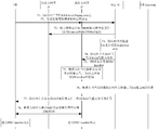
- FIG. 4 is a schematic diagram showing a main implementation process of determining a paging area at a radio access network level in a process of attaching a terminal to a network or initiating a location update;
- FIG. 5 is a schematic diagram showing a main implementation process of determining a paging area at a radio access network level in a process of initiating a service request by a terminal;
- FIG. 6 is a schematic diagram showing a main implementation process of a method for reallocating a paging area of a radio access network level triggered by a core network node in a process in which a terminal moves out of a paging area of a current radio access network level in some embodiments;
- FIG. 7 is a schematic diagram showing a main implementation process of a method for reallocating a paging area at a radio access network level triggered by a core network node in a process in which a terminal moves out of a paging area at a current radio access network level in some embodiments;
- FIG. 8 is a schematic diagram showing a main implementation process of redistribution of a paging area at a radio access network level directly triggered by a terminal during a process of removing a paging area of a current radio access network level by a terminal;
- FIG. 9 is a block diagram showing an access network node in some embodiments of the present disclosure.
- FIG. 10 is a schematic structural diagram of an access network node in some embodiments of the present disclosure.
- FIG. 11 is a flow chart showing a method of determining a paging area in some embodiments of the present disclosure
- FIG. 12 is a block diagram showing a core network node in some embodiments of the present disclosure.
- FIG. 13 is a block diagram showing the structure of a core network node in some embodiments of the present disclosure.
- the present disclosure is directed to a related art that does not perform a scheme of updating or reallocating a paging area after a UE moves out of a paging area of a current RAN level, thereby affecting a problem of network communication, and providing a method for determining a paging area.
- access network nodes and core network nodes are not perform a scheme of updating or reallocating a paging area after a UE moves out of a paging area of a current RAN level, thereby affecting a problem of network communication.
- an embodiment of the present disclosure provides a method for determining a paging area, which is applied to an access network node, and includes the following steps.
- Step 31 Obtain indication information for performing paging area allocation for the terminal.
- the method is mainly for determining a paging area of a radio access network level in a RRC inactive state (ie, an RRC_inactive_connected state in the background art), and the indication information may be sent to the core network node.
- the ingress node may also be directly sent by the terminal to the access network node, and it should be noted that when the terminal does not enter the RRC inactive state, the indication information is used to indicate that the terminal performs paging area allocation, and When the terminal is already in the RRC inactive state, the indication information is used to indicate that the paging area is re-allocated for the terminal (that is, the paging area is updated at this time).
- Step 32 Determine, according to the indication information, a paging area for the terminal.
- the access network node receives the indication information, the paging area of the radio access network level is determined for the terminal according to the indication information.
- Step 33 Notifying the paging area to the terminal.
- the access network node in this embodiment refers to an access network node that is currently serving the terminal.
- the embodiment of the present disclosure determines the paging area of the terminal according to the indication information of the paging area allocation for the terminal, and implements the determination of the paging area of the radio access network level in the RRC inactive state, thereby ensuring network communication. Integrity.
- the access network node may control the terminal to enter the RRC inactive state during the process of attaching the terminal to the network or initiate the location update process, and allocate the paging area of the radio access network level to the terminal.
- the indication information may be an area information that the terminal is allowed to use the radio resource to control the RRC inactive state or an indication that the terminal is allowed to use the RRC inactive state; in this case, the access network node passes the paging area through the air interface message. (for example, an RRC message) is directly sent to the terminal, and when the terminal is again connected to the access network node, the access network node re-determines the paging area of the radio access network level for the terminal.
- the indication information is: the area information that the terminal is allowed to use the radio resource to control the RRC inactive state; or the terminal allows the indication of the RRC inactive state to be used.
- the indication that the terminal is allowed to activate the RRC inactive state may be implicit.
- An indication such as a terminal low mobility indication or a terminal non-movement indication.
- the step 32 is specifically implemented, and includes: in the area information that the terminal is allowed to use the RRC inactive state, the terminal is A paging area based on cell granularity is determined, wherein the determined cell granularity based paging area is included by an area in which the terminal is allowed to use the RRC inactive state. It should be noted that, when the core network node indicates to the access network node that the terminal allows to use the RRC inactive state information, the access network node needs to select a part of the indicated area information as the new determined by the terminal. Paging area.
- the step 32 is specifically implemented, including: determining, according to the indication that the terminal is allowed to use the RRC inactive state, determining a paging area based on the cell granularity of the terminal. .
- the access network node when the core network node indicates to the access network node that the terminal allows to use the RRC inactive state information, the access network node directly determines the new paging for the terminal according to the mobility information of the terminal and the network side information. region.
- the main manner of determining a paging area based on cell granularity for a terminal is: acquiring network deployment and configuration on the access network node side and mobility characteristic information of the terminal; according to the network deployment and configuration and the The mobility characteristic information of the terminal is used to determine a paging area based on the cell granularity for the terminal.
- the main implementation process of determining the paging area of the radio access network level is:
- step 41 the UE attaches to the network or initiates a location update procedure.
- Step 42 Determine an RRC inactive allowed area of the terminal.
- the core network node determines whether the terminal can use the RRC inactive connected state according to the mobility of the UE, the UE's subscription, the network configuration and the policy, etc. (that is, using the RRC inactive model or entering the RRC inactive connected state).
- the terminal can use the RRC inactive connected state, determine that the UE can enter the RRC inactive connected state, record the RRC inactive allowed area, and allocate the tracking area list (TA list) or the cell.
- TA list tracking area list
- a cell list covers the RRC inactive allowed area.
- Step 43 Send indication information for paging area allocation of the terminal to the access network node;
- the core network node indicates the access network node of the currently serving UE, and indicates that the UE is allowed to use RRC inactive. Further, the core network node (for example, the mobility management function entity) will allow the UE to send to the RAN node using the RRC inactive area.
- Step 44 Establish a control plane connection and a user plane connection between the access network node and the core network node, that is, establish a connection between the NG2 interface and the NG3 interface.
- step 45 the core network node allocates a tracking area list or a cell list to the UE.
- Step 46 The access network node determines, according to the indication information of the core network node, a paging area of the RAN level for the terminal;
- the access network node receives the RRC inactive allowed area, further according to the network deployment and configuration on the access network side (for example, the access network node as an anchor point, the serviceable area), and the mobility characteristics of the UE, The UE allocates a UE-specific RAN level paging area, and determines that the UE can use the RRC inactive connected state in the paging area, and ensures that the paging area of the RAN level is included by the RRC inactive allowed area.
- the network deployment and configuration according to the access network side (for example, the access network node as an anchor point, the serviceable area) and the mobility of the UE A feature is to allocate a UE-specific RAN level paging area for the UE, and determine that the UE can use the RRC inactive connected state in the paging area.
- step 47 the access network node notifies the paging area to the UE.
- Step 48 After releasing the RRC connection, the UE and the access network node enter an RRC inactive state.
- the main implementation process of determining the paging area at the radio access network level is:
- Optional step in the terminal Attach (but not establishing a PDU session) or the TAU process, when the core network node (for example, the mobility management function entity) determines whether the terminal is based on the mobility of the UE, the subscription of the UE, the network configuration and the policy, and the like.
- the core network node for example, the mobility management function entity
- the core network node determines whether the terminal is based on the mobility of the UE, the subscription of the UE, the network configuration and the policy, and the like.
- the core network node for example, the mobility management function entity
- Step 51 The UE initiates a Service Request process.
- Step 52 Send indication information for paging area allocation of the terminal to the access network node
- the core network may indicate to the RAN node the access network node of the currently serving UE (this indication is optional, if the mobility management function has provided an indication to the RAN node in the Attach or TAU procedure, no provision is required), the UE RRC inactive is allowed to be used. Further, the mobility management function will allow the UE to send to the RAN node using the RRC inactive area.
- step 53 the data transmission path of the user plane is established and data transmission is performed.
- Step 54 The access network node determines to allocate the RAN level paging area according to the current indication of the core network node or the indication that has been received before.
- the RAN node receives the RRC inactive allowed area, further according to the network deployment and configuration on the access network side (for example, the access network node as an anchor point, the serviceable area), and the mobility characteristics of the UE, the UE A UE-specific RAN level paging area is allocated, and it is determined that the UE can use the RRC inactive connected state in the paging area, and the paging area of the RAN level is guaranteed to be included in the RRC inactive allowed area.
- the access network node If the access network node only receives the indication that the RRC inactive state is allowed to be used, it is deployed and configured according to the network on the access network side (for example, the access network node acts as an anchor point, the area that can be served), and the UE
- the mobility feature allocates a UE-specific RAN level paging area for the UE, and determines that the UE can use the RRC inactive connected state in the paging area.
- Step 55 The access network node notifies the paging area to the UE during the RRC connection release process, and after releasing the RRC connection, the UE and the access network node enter the RRC inactive state.
- the core network node when the terminal has entered the RRC inactive state, when the current paging area is removed during the mobile process, the core network node triggers the access network node to perform reallocation of the paging area for the terminal, in which case
- the specific implementation manner of the step 31 is: acquiring the indication information that the core network node sends the paging area allocation for the terminal when receiving the location update request of the terminal.
- step 32 is:
- the paging area is directly sent to the terminal through an air interface message.
- the main implementation process of the mode 1 of redistribution of the paging area at the radio access network level triggered by the core network node in the process of the terminal moving out of the paging area at the current radio access network level for:
- Step 61 After the UE moves out of the current RAN level Paging area, the location update request is sent to the core network node, where the location update request carries an indication to remove the RAN level Paging area (if the RAN level Paging area and the TA list or the cell list are not aligned) ).
- step 62 the core network node first notifies the original access network node to delete the context (Context) of the UE and the NG2 and NG3 connections.
- step 63 the core network node checks if the UE is still in the allowed area.
- the step 63 is an optional step. When the RAN level Paging area may be greater than the TA list or the cell list, the step 63 is performed.
- Step 64 The core network node indicates an access network node (new access network node) of the currently serving UE, and the UE is allowed to use RRC inactive. Further, the core network node will allow the UE to use the RRC inactive area to send to the new access network. node.
- Step 65 When the new access network node allocates a UE-specific RAN level paging area according to the indication of the core network node (that is, the area that the core network node sends to allow the UE to use the RRC inactive area), and determines that the UE is in the The paging area can use the RRC inactive connected state.
- the indication of the core network node that is, the area that the core network node sends to allow the UE to use the RRC inactive area
- Step 66 The new access network node establishes an NG3 connection for the UE according to the indication of the core network node.
- step 67 the new access network node notifies the paging area to the core network node.
- Step 68 The core network node notifies the UE of the newly allocated paging area, so that the UE and the RAN enter the RRC inactive state after releasing the RRC connection.
- the main implementation process of the mode 2 of redistribution of the paging area at the radio access network level triggered by the core network node in the process of the terminal moving out of the paging area at the current radio access network level for:
- Step 71 After the UE moves out of the current RAN level Paging area, the location update request is sent to the core network node, where the location update request may carry an indication of moving out of the RAN level Paging area (for example, in the RAN level Paging area and the TA list or the cell list). When not aligned, the UE provides the indication to the core network node).
- Step 72 The core network node first notifies the original access network node to delete the context of the UE (Context). Connected to NG2 and NG3.
- Step 73 the core network node checks whether the UE is still in the allowed area
- the step 73 is an optional step. When the RAN level Paging area may be greater than the TA list or the cell list, the step 73 is performed.
- Step 74 The core network node indicates an access network node (new access network node) of the currently serving UE, and the UE is allowed to use RRC inactive. Further, the core network node will allow the UE to use the RRC inactive area to send to the new access network. node.
- new access network node new access network node
- Step 75 The new access network node allocates a UE-specific RAN level paging area to the UE according to the indication of the core network node (that is, the area that the core network node sends to allow the UE to use the RRC inactive area), and determines that the UE is in the search.
- the call zone can use the RRC inactive connected state.
- Step 76 The new access network node establishes an NG3 connection for the UE according to the indication of the core network node.
- Step 77 After completing the NG3 connection establishment, the core network node returns a location update accept message to the UE.
- Step 78 The new access network node notifies the UE of the new paging area by using the RRC message, for example, an RRC connection release message, so that the UE and the access network node of the currently serving UE enter the RRC inactive state after releasing the RRC connection.
- the RRC message for example, an RRC connection release message
- the terminal when the terminal has entered the RRC inactive state, when the current paging area is removed during the mobile process, the terminal directly triggers the access network node to perform reallocation of the paging area for the terminal, in which case
- the specific implementation manner of the step 31 is: after the receiving terminal moves out of the current paging area, the sending information indicating that the terminal performs paging area allocation.
- the indication information may be included in the request message sent by the terminal, or may be a new message sent by the terminal.
- the request message may need to carry the previously camped cell information, so as to enable access at the service terminal.
- the access network node that receives the terminal request message can find the previous access network node (ie, the first access network node).
- the method includes:
- Step 321 Determine, according to the indication information, whether the terminal can use the RRC inactive state.
- Step 322 If the terminal can use the RRC inactive state, determine the paging area for the terminal.
- Step 323 If the terminal cannot use the RRC inactive state, send an RRC inactive state deactivation message to the core network node, so that the core network node notifies the terminal that the RRC inactive state cannot be used.
- the step 321 may include:
- Step 3211 Acquire, according to the indication information, area information that the terminal is allowed to use the RRC inactive state;
- step 321 is: sending a request to the first access network node to obtain the area information of the terminal that is allowed to use the RRC inactive state; or
- the first access network node refers to an access network node of the original serving terminal, that is, an old access network node.
- the current access network node may obtain the cell information query that is camped on by the terminal.
- Step 3212 Determine, according to the area information that the terminal is allowed to use the RRC inactive state, whether the terminal can use the RRC inactive state.
- the method for determining a paging area further includes:
- the access network node directly sends the paging area to the terminal through an air interface message.
- the main implementation process of the re-allocation of the paging area at the radio access network level directly triggered by the terminal is:
- Step 81 After the UE moves out of the current RAN level Paging area, the RRC message including the indication information of the requested paging area allocation is sent to the access network node to request re-allocation of the RAN level Paging area, where the indication information includes the old cell ( Old cell)ID. If the RRC message is sent to the original access network node, the RAN level Paging area is re-allocated by the original access network node, and the UE is notified, otherwise step 82 is performed.
- Step 82 The new access network node sends a message to the original access network node, requesting to perform a similar X2 handover procedure or a new UE context delivery procedure, in order to obtain the UE mobility from the original access network node.
- Sexual Context and Session Context At the same time, the original access network node should provide the allowed area to the new access network node.
- step 83 the original access network node feeds back relevant information to the new access network node.
- Step 84 The new access network node determines, according to the allowed area, that the UE can use the RRC inactive state (for example, the service area of the new access network node overlaps with the allowed area), and the new access network node allocates the UE specific RAN level to the UE. Paging the area and determining that the UE can use the RRC inactive connected state in the area. If the New RAN node determines that the UE cannot continue to use the RRC inactive state, rejects the UE's request and indicates that the UE cannot continue to use the RRC inactive state.
- Step 85 The new access network node sends a path switch request to the core network node.
- step 86 the NG2, NG3 connection of the UE is updated, and the connection establishment of the NG3 is completed by the core network node.
- Step 87 The new access network node notifies the UE of the new paging area by using the RRC message, for example, an RRC connection release message, so that the UE and the RAN enter the RRC inactive state after releasing the RRC connection.
- the RRC message for example, an RRC connection release message
- step 88 the new access network node notifies the original access network node to delete the Context, NG2, and NG3 connections of the UE.
- the core network node determines that the UE cannot continue to use RAN level Paging (for example, the UE leaves in the allowed area).
- the core network node notifies the original access network node to delete the Context, NG2, and NG3 connections of the UE, and the core network node returns a location update accept message, notifying the UE that the RRC inactive state cannot be used, and possibly assigning a new TA list.
- the paging area of the radio access network level of the terminal is determined, and the paging area of the radio access network level of the terminal in the RRC inactive state is implemented.
- the determination ensures the integrity of the network communication.
- an embodiment of the present disclosure provides an access network node 90, including: a first obtaining module 91, configured to acquire indication information for paging area allocation for a terminal; The module 92 is configured to determine a paging area for the terminal according to the indication information, and the notification module 93 is configured to notify the terminal of the paging area.
- the indication information is: the terminal allows to use the radio resource to control the RRC inactive state. Area information; or the terminal allows the use of an indication of the RRC inactive state.
- the first determining module 92 is configured to: determine a cell granularity-based paging for the terminal according to the indication that the terminal is allowed to use the RRC inactive state. region.
- the first determining module 92 is configured to: in the area information that the terminal is allowed to use the RRC inactive state, A paging area based on cell granularity is determined for the terminal, wherein the determined cell granularity based paging area is included by the terminal allowing the area in which the RRC inactive state is used.
- the manner of determining, by the terminal, the paging area based on the cell granularity is: acquiring network deployment and configuration on the access network node side and mobility characteristic information of the terminal; according to the network deployment and configuration, and the The mobility characteristic information of the terminal determines a paging area based on the cell granularity for the terminal.
- the notification module 93 is configured to send the paging area directly to the terminal by using an air interface message.
- the access network node 90 further includes: a second determining module, when the terminal is connected to the access network node again, the access network node re-determines the paging area for the terminal.
- the first obtaining module 91 is configured to: obtain, when the core network node receives the location update request of the terminal, the indication information that is sent by the terminal for paging area allocation.
- the notification module 93 is configured to: send the paging area to the core network node, so that the core network node sends the paging area to the terminal; or the paging area The air interface message is directly sent to the terminal.
- the first obtaining module 91 is configured to: after receiving, by the terminal, the terminal, the indication information for performing paging area allocation for the terminal after the current paging area is removed.
- the first determining module 92 includes: a determining submodule, configured to determine, according to the indication information, whether the terminal can use the RRC inactive state; and the first determining submodule is configured to: if the terminal can use the RRC inactive state , the paging area is determined for the terminal.
- the determining sub-module includes: an obtaining unit, configured to acquire, according to the indication information, area information that the terminal is allowed to use an RRC inactive state; and a determining unit, configured to use, according to the terminal, an area that is allowed to use an RRC inactive state Information, determine whether the terminal can use RRC is not active status.
- the acquiring unit is configured to: send a request to the first access network node to obtain the area information of the terminal that is allowed to use the RRC inactive state; or send a request to the core network node to obtain the terminal. Area information of the RRC inactive state is allowed to be used.
- the first determining module 92 further includes: a first sending submodule, configured to send an RRC inactive state deactivation message to the core network node if the terminal cannot use the RRC inactive state, so that the core network node Notifying the terminal that the RRC inactivity state cannot be continued.
- a first sending submodule configured to send an RRC inactive state deactivation message to the core network node if the terminal cannot use the RRC inactive state, so that the core network node Notifying the terminal that the RRC inactivity state cannot be continued.
- the access network node 90 further includes: a first sending module, configured to send a path switching request to the core network node, so that the core network node updates the access network node and the core network node for the terminal The control plane connection and the user plane connection.
- a first sending module configured to send a path switching request to the core network node, so that the core network node updates the access network node and the core network node for the terminal The control plane connection and the user plane connection.
- the notification module 93 is configured to: directly send the paging area to the terminal by using an air interface message.
- the embodiment of the access network node is an access network node corresponding to the foregoing method embodiment, and all implementation manners in the foregoing method embodiments are applicable to the embodiment of the access network node. Can also achieve the same technical effect.
- an embodiment of the present disclosure provides an access network node, including: a processor 101; and a memory 103 connected to the processor 101 through a bus interface 102, the memory 103 is configured to store programs and data used by the processor 101 when performing operations, and when the processor 101 calls and executes programs and data stored in the memory 103, the following process is performed: obtaining paging for the terminal The indication information of the area allocation; determining, according to the indication information, a paging area for the terminal; and using the transceiver 104 to notify the terminal of the paging area.
- processor 101 is further configured to implement the functions of any other module of the foregoing access network node.
- transceiver 104 is connected to the bus interface 102 for notifying the paging area to the terminal under the control of the processor 101.
- the bus architecture may include any number of interconnected buses and bridges, specifically linked by one or more processors represented by processor 101 and various circuits of memory represented by memory 103.
- the bus architecture can also link various other circuits, such as peripherals, voltage regulators, and power management circuits, as is known in the art, and thus, This article will not be further described.
- the bus interface provides an interface.
- the transceiver 104 can be a plurality of components, including a transmitter and a transceiver, providing means for communicating with various other devices on a transmission medium.
- the processor 101 is responsible for managing the bus architecture and general processing, and the memory 103 can store data used by the processor 101 in performing operations.
- the method for determining a paging area is applied to a core network node, including: step 111, acquiring a location update request of the terminal; and step 112, updating according to the location And determining, by the terminal, whether the terminal is allowed to use the radio resource to control the RRC inactive state; and in step 113, if the radio resource is used to control the RRC inactive state, sending the indication information for the paging area allocation of the terminal to the access network node.
- the indication information includes: an area information provided by the core network node to allow the RRC inactive state to be controlled by using the radio resource, or an indication that the terminal is allowed to use the RRC inactive state.
- the specific implementation manner of the step 111 is: sending a location update request when the terminal moves out of the current paging area, where the location update request includes indication information that the terminal removes the current paging area.
- the step 113 when implemented, includes: determining area information that allows the terminal to use the RRC inactive state; The information is sent to the access network node as indication information for the terminal to perform paging area allocation.
- the determining the paging area further includes: determining whether the terminal is in an area that is allowed to use the RRC inactive state; if the terminal is in an area that is allowed to use the RRC inactive state, performing the step If the terminal is not in an area where the RRC inactive state is allowed to be used, return a response message (for example, a location update accept message) to the terminal, and notify the terminal that the RRC inactivity state cannot be continued.
- a response message for example, a location update accept message
- the method for determining a paging area further includes: receiving a paging area fed back by an access network node; and sending the paging area to the terminal.
- the embodiment of the present disclosure provides a core network node 120, including: a second obtaining module 121, configured to acquire a location update request of the terminal; and a third determining module 122, configured to The location update request determines whether the terminal is allowed to use the radio resource to control the RRC inactive state; and the second sending module 123 is configured to: if the radio resource is used to control the RRC inactive state, send the indication information that the terminal performs paging area allocation Give the access network node.
- the indication information includes: an area information provided by the core network node to allow the RRC inactive state to be controlled by using the radio resource, or an indication that the terminal is allowed to use the RRC inactive state.
- the second obtaining module 121 is configured to: receive a location update request that is sent when the terminal moves out of the current paging area, where the location update request includes indication information that the terminal removes the current paging area.
- the second sending module 123 includes: a second determining submodule, configured to determine that the terminal is allowed to use the RRC inactive state.
- the area information is sent to the access network node by using the area information as indication information for the terminal to perform paging area allocation.
- the core network node 120 further includes: a determining module, configured to determine whether the terminal is in an area that allows the RRC inactive state to be used; and if the terminal is in an area that allows the RRC inactive state to be used, The third determining module performs, according to the location update request, a step of determining whether the terminal is allowed to use the radio resource to control the RRC inactive state, and a message returning module, configured to: if the terminal is not in an area where the RRC inactive state is allowed to be used, The terminal returns a location update accept message, notifying the terminal that the RRC inactivity state cannot be continued.
- a determining module configured to determine whether the terminal is in an area that allows the RRC inactive state to be used; and if the terminal is in an area that allows the RRC inactive state to be used, The third determining module performs, according to the location update request, a step of determining whether the terminal is allowed to use the radio resource to control the RRC inactive state
- a message returning module configured to:
- the core network node 120 further includes: a receiving module, configured to receive a paging area that is fed back by the access network node, and a third sending module, configured to send the paging area to the terminal.
- a receiving module configured to receive a paging area that is fed back by the access network node
- a third sending module configured to send the paging area to the terminal.
- the embodiment of the core network node is a core network node corresponding to the foregoing method embodiment. All the implementation manners in the foregoing method embodiments are applicable to the embodiment of the core network node, and can also be achieved. The same technical effect.
- an embodiment of the present disclosure provides a core network node, including: a processor 131; and a memory connected to the processor 131 through a bus interface 132. 133.
- the memory 133 is configured to store programs and data used by the processor 131 when performing an operation.
- the processor 131 calls and executes the programs and data stored in the memory 133, the following process is performed: acquiring a location update request of the terminal; determining, according to the location update request, whether the terminal is allowed to use the radio resource to control the RRC inactive state; if the radio resource is used to control the RRC inactive state, transmitting, by the transceiver 134, paging area allocation for the terminal
- the indication information is given to the access network node.
- processor 131 is further configured to implement the functions of any other module of the core network node.
- the transceiver 134 is connected to the bus interface 132 for transmitting indication information for paging allocation of the terminal to the access network node under the control of the processor 131.
- the bus architecture may include any number of interconnected buses and bridges, specifically linked by one or more processors represented by processor 131 and various circuits of memory represented by memory 133.
- the bus architecture can also link various other circuits such as peripherals, voltage regulators, and power management circuits, which are well known in the art and, therefore, will not be further described herein.
- the bus interface provides an interface.
- Transceiver 134 may be a plurality of components, including a transmitter and a transceiver, providing means for communicating with various other devices on a transmission medium.
- the processor 131 is responsible for managing the bus architecture and general processing, and the memory 133 can store data used by the processor 131 in performing operations.
Landscapes
- Engineering & Computer Science (AREA)
- Computer Networks & Wireless Communication (AREA)
- Signal Processing (AREA)
- Databases & Information Systems (AREA)
- Mobile Radio Communication Systems (AREA)
Abstract
L'invention concerne un procédé de détermination d'une zone de radiomessagerie, un nœud de réseau d'accès et un nœud de réseau central. Le procédé de détermination d'une zone de radiomessagerie est appliqué à un nœud de réseau d'accès, et comprend les étapes consistant à : acquérir des informations d'indication concernant la distribution d'une zone de radiomessagerie pour un terminal ; en fonction des informations d'indication, déterminer une zone de radiomessagerie pour le terminal ; et notifier au terminal la zone de radiomessagerie.
Priority Applications (4)
| Application Number | Priority Date | Filing Date | Title |
|---|---|---|---|
| EP17860229.8A EP3528562B1 (fr) | 2016-10-11 | 2017-09-20 | Procédé de détermination de zone de radiomessagerie, noeud de réseau d'accès et noeud de réseau central |
| KR1020197013315A KR102207468B1 (ko) | 2016-10-11 | 2017-09-20 | 페이징 영역 확정 방법, 접속망 노드 및 코어망 노드 |
| JP2019540480A JP6750126B2 (ja) | 2016-10-11 | 2017-09-20 | ページングエリア特定方法、アクセスネットワークノードおよびコアネットワークノード |
| US16/340,577 US10972999B2 (en) | 2016-10-11 | 2017-09-20 | Method for determining paging area, access network node and core network node |
Applications Claiming Priority (2)
| Application Number | Priority Date | Filing Date | Title |
|---|---|---|---|
| CN201610887826.3A CN108377516B (zh) | 2016-10-11 | 2016-10-11 | 一种确定寻呼区域的方法、接入网节点及核心网节点 |
| CN201610887826.3 | 2016-10-11 |
Publications (1)
| Publication Number | Publication Date |
|---|---|
| WO2018068614A1 true WO2018068614A1 (fr) | 2018-04-19 |
Family
ID=61905134
Family Applications (1)
| Application Number | Title | Priority Date | Filing Date |
|---|---|---|---|
| PCT/CN2017/102375 Ceased WO2018068614A1 (fr) | 2016-10-11 | 2017-09-20 | Procédé de détermination de zone de radiomessagerie, nœud de réseau d'accès et nœud de réseau central |
Country Status (6)
| Country | Link |
|---|---|
| US (1) | US10972999B2 (fr) |
| EP (1) | EP3528562B1 (fr) |
| JP (1) | JP6750126B2 (fr) |
| KR (1) | KR102207468B1 (fr) |
| CN (1) | CN108377516B (fr) |
| WO (1) | WO2018068614A1 (fr) |
Families Citing this family (11)
| Publication number | Priority date | Publication date | Assignee | Title |
|---|---|---|---|---|
| CN108282818B (zh) * | 2017-01-06 | 2020-11-17 | 中兴通讯股份有限公司 | 一种ran通知范围信息处理方法及装置 |
| KR102571341B1 (ko) * | 2017-02-03 | 2023-08-29 | 주식회사 아이티엘 | 무선 통신 시스템에서 단말의 이동성을 지원하는 네트워크 및 단말의 동작 방법 및 장치 |
| US11184791B2 (en) * | 2017-03-25 | 2021-11-23 | Lg Electronics Inc. | Access control method and device for supporting same |
| CN111757358B (zh) | 2017-08-28 | 2023-08-25 | Oppo广东移动通信有限公司 | 用于寻呼的方法、接入网设备和终端设备 |
| CN112313979B (zh) * | 2018-09-28 | 2023-06-23 | Oppo广东移动通信有限公司 | 一种信息传输方法及装置、网络设备 |
| CN112437393B (zh) * | 2019-08-07 | 2022-05-31 | 大唐移动通信设备有限公司 | 一种可达性区域配置方法、设备及装置 |
| US12342411B2 (en) * | 2019-12-18 | 2025-06-24 | Qualcomm Incorporated | Fast connection release after paging response |
| CN113678521A (zh) * | 2020-03-13 | 2021-11-19 | 北京小米移动软件有限公司 | 一种信息处理方法方法及装置、通信设备及存储介质 |
| TWI819462B (zh) * | 2021-01-13 | 2023-10-21 | 瑞典商Lm艾瑞克生(Publ)電話公司 | 用於移動性更新報告之技術 |
| WO2025063707A1 (fr) * | 2023-09-19 | 2025-03-27 | 엘지전자 주식회사 | Procédé et appareil de recherche et d'accès à une cellule pour prendre en charge une couverture multiple |
| JP7772762B2 (ja) * | 2023-11-21 | 2025-11-18 | ソフトバンク株式会社 | 基地局装置、基地局装置切り替え方法およびプログラム |
Citations (1)
| Publication number | Priority date | Publication date | Assignee | Title |
|---|---|---|---|---|
| CN105188137A (zh) * | 2014-05-23 | 2015-12-23 | 中国移动通信集团内蒙古有限公司 | 一种分组交换域寻呼方法及装置 |
Family Cites Families (5)
| Publication number | Priority date | Publication date | Assignee | Title |
|---|---|---|---|---|
| US9578567B1 (en) * | 2014-08-26 | 2017-02-21 | Luminate Wireless, Inc. | Data center relocation methods and apparatus |
| CN105744621A (zh) * | 2014-12-08 | 2016-07-06 | 中兴通讯股份有限公司 | 寻呼处理方法及装置 |
| EP3231247A1 (fr) * | 2014-12-12 | 2017-10-18 | Telefonaktiebolaget LM Ericsson (publ) | Procédé et noeud de gestion de signalisation de plan de commande |
| CN105848223A (zh) * | 2016-03-02 | 2016-08-10 | 深圳市金立通信设备有限公司 | 一种网络连接的控制方法及设备 |
| EP3975636B1 (fr) * | 2016-09-21 | 2024-03-20 | Kyocera Corporation | Station de base et terminal radio |
-
2016
- 2016-10-11 CN CN201610887826.3A patent/CN108377516B/zh active Active
-
2017
- 2017-09-20 WO PCT/CN2017/102375 patent/WO2018068614A1/fr not_active Ceased
- 2017-09-20 JP JP2019540480A patent/JP6750126B2/ja active Active
- 2017-09-20 KR KR1020197013315A patent/KR102207468B1/ko active Active
- 2017-09-20 US US16/340,577 patent/US10972999B2/en active Active
- 2017-09-20 EP EP17860229.8A patent/EP3528562B1/fr active Active
Patent Citations (1)
| Publication number | Priority date | Publication date | Assignee | Title |
|---|---|---|---|---|
| CN105188137A (zh) * | 2014-05-23 | 2015-12-23 | 中国移动通信集团内蒙古有限公司 | 一种分组交换域寻呼方法及装置 |
Non-Patent Citations (4)
| Title |
|---|
| "RAN initiated Paging Solution", 3GPP TSG-RAN 3 MEETING #92 R3-161167, 27 May 2016 (2016-05-27), XP051094841 * |
| ASUSTEK.: "On the paging area management for light connection", 3GPP TSG-RAN WG 2 MEETING #95 R2-165303, 26 August 2016 (2016-08-26), XP051126871 * |
| CHINA TELECOM.: "Discussion on the paging area for light connection", 3GPP TSG RAN WG 2 MEETING #94 R2-163860, 27 May 2016 (2016-05-27), XP051095656 * |
| HUAWEI ET AL.: "Signalling reduction to enable light connection for LTE", 3GPP TSG RAN MEETING #73 RP-161805, 22 September 2016 (2016-09-22), XP055476679 * |
Also Published As
| Publication number | Publication date |
|---|---|
| US10972999B2 (en) | 2021-04-06 |
| JP2019535219A (ja) | 2019-12-05 |
| EP3528562A4 (fr) | 2019-09-25 |
| EP3528562A1 (fr) | 2019-08-21 |
| JP6750126B2 (ja) | 2020-09-02 |
| CN108377516A (zh) | 2018-08-07 |
| KR102207468B1 (ko) | 2021-01-25 |
| KR20190062540A (ko) | 2019-06-05 |
| US20190239188A1 (en) | 2019-08-01 |
| CN108377516B (zh) | 2019-12-10 |
| EP3528562B1 (fr) | 2021-03-03 |
Similar Documents
| Publication | Publication Date | Title |
|---|---|---|
| WO2018068614A1 (fr) | Procédé de détermination de zone de radiomessagerie, nœud de réseau d'accès et nœud de réseau central | |
| US12063559B2 (en) | Method and apparatus for complementary and equivalent network slice deployment in a network environment | |
| US20200127968A1 (en) | Information processing method and apparatus | |
| US10499326B2 (en) | User equipment paging method and MME | |
| CN109548109B (zh) | 一种ue和网络状态不匹配的处理方法及装置、存储介质 | |
| US11159934B2 (en) | Presence reporting areas for the UE | |
| WO2019137142A1 (fr) | Procédé de communication associé à une politique, dispositif et système | |
| WO2018205153A1 (fr) | Procédé, terminal et système de gestion de session | |
| WO2019076060A1 (fr) | Procédé, dispositif et système de réacheminement de données | |
| US11452162B2 (en) | Session management method, mobility management functional entity and session management functional entity | |
| US11082893B2 (en) | Session migration method and device applied to a UE tracking area update | |
| RU2742219C1 (ru) | Способ и устройство управления подключением плоскости управления | |
| WO2019096306A1 (fr) | Procédé de traitement de requêtes, et entité correspondante | |
| WO2019091077A1 (fr) | Procédé et dispositif de déclenchement de commutation de réseau, et support de stockage informatique | |
| WO2018233451A1 (fr) | Procédé, appareil et système de communication | |
| WO2019029228A1 (fr) | Procédé et dispositif de traitement de service vocal et support de stockage | |
| CN109392094A (zh) | 一种非活动状态的辅助方法、设备及系统 | |
| CN109819487B (zh) | 一种连接管理方法及设备 | |
| WO2018119853A1 (fr) | Procédé, dispositif et système de libération de contexte | |
| WO2011060663A1 (fr) | Procédé et centre de commutation mobile (msc) pour implémenter une redistribution de charge | |
| CN116321530B (zh) | 一种冗余信息处理方法、系统、电子设备与存储介质 | |
| KR20090091183A (ko) | 트렁킹 시스템 중 페이징 방법 및 장치 | |
| CN112118606A (zh) | 实现业务连续的方法、相关装置及系统 | |
| WO2011150649A1 (fr) | Procédé et dispositif de réallocation de passerelle de données par paquets | |
| CN114449486A (zh) | 一种边缘计算服务漫游的方法及装置 |
Legal Events
| Date | Code | Title | Description |
|---|---|---|---|
| ENP | Entry into the national phase |
Ref document number: 2019540480 Country of ref document: JP Kind code of ref document: A |
|
| NENP | Non-entry into the national phase |
Ref country code: DE |
|
| ENP | Entry into the national phase |
Ref document number: 20197013315 Country of ref document: KR Kind code of ref document: A |
|
| ENP | Entry into the national phase |
Ref document number: 2017860229 Country of ref document: EP Effective date: 20190513 |