WO2018070022A1 - 自己位置推定方法及び自己位置推定装置 - Google Patents
自己位置推定方法及び自己位置推定装置 Download PDFInfo
- Publication number
- WO2018070022A1 WO2018070022A1 PCT/JP2016/080387 JP2016080387W WO2018070022A1 WO 2018070022 A1 WO2018070022 A1 WO 2018070022A1 JP 2016080387 W JP2016080387 W JP 2016080387W WO 2018070022 A1 WO2018070022 A1 WO 2018070022A1
- Authority
- WO
- WIPO (PCT)
- Prior art keywords
- target
- host vehicle
- surrounding situation
- vehicle
- map data
- Prior art date
- Legal status (The legal status is an assumption and is not a legal conclusion. Google has not performed a legal analysis and makes no representation as to the accuracy of the status listed.)
- Ceased
Links
Images





Classifications
-
- B—PERFORMING OPERATIONS; TRANSPORTING
- B60—VEHICLES IN GENERAL
- B60W—CONJOINT CONTROL OF VEHICLE SUB-UNITS OF DIFFERENT TYPE OR DIFFERENT FUNCTION; CONTROL SYSTEMS SPECIALLY ADAPTED FOR HYBRID VEHICLES; ROAD VEHICLE DRIVE CONTROL SYSTEMS FOR PURPOSES NOT RELATED TO THE CONTROL OF A PARTICULAR SUB-UNIT
- B60W30/00—Purposes of road vehicle drive control systems not related to the control of a particular sub-unit, e.g. of systems using conjoint control of vehicle sub-units
- B60W30/06—Automatic manoeuvring for parking
-
- B—PERFORMING OPERATIONS; TRANSPORTING
- B60—VEHICLES IN GENERAL
- B60K—ARRANGEMENT OR MOUNTING OF PROPULSION UNITS OR OF TRANSMISSIONS IN VEHICLES; ARRANGEMENT OR MOUNTING OF PLURAL DIVERSE PRIME-MOVERS IN VEHICLES; AUXILIARY DRIVES FOR VEHICLES; INSTRUMENTATION OR DASHBOARDS FOR VEHICLES; ARRANGEMENTS IN CONNECTION WITH COOLING, AIR INTAKE, GAS EXHAUST OR FUEL SUPPLY OF PROPULSION UNITS IN VEHICLES
- B60K35/00—Instruments specially adapted for vehicles; Arrangement of instruments in or on vehicles
- B60K35/10—Input arrangements, i.e. from user to vehicle, associated with vehicle functions or specially adapted therefor
-
- B—PERFORMING OPERATIONS; TRANSPORTING
- B60—VEHICLES IN GENERAL
- B60K—ARRANGEMENT OR MOUNTING OF PROPULSION UNITS OR OF TRANSMISSIONS IN VEHICLES; ARRANGEMENT OR MOUNTING OF PLURAL DIVERSE PRIME-MOVERS IN VEHICLES; AUXILIARY DRIVES FOR VEHICLES; INSTRUMENTATION OR DASHBOARDS FOR VEHICLES; ARRANGEMENTS IN CONNECTION WITH COOLING, AIR INTAKE, GAS EXHAUST OR FUEL SUPPLY OF PROPULSION UNITS IN VEHICLES
- B60K35/00—Instruments specially adapted for vehicles; Arrangement of instruments in or on vehicles
- B60K35/20—Output arrangements, i.e. from vehicle to user, associated with vehicle functions or specially adapted therefor
- B60K35/28—Output arrangements, i.e. from vehicle to user, associated with vehicle functions or specially adapted therefor characterised by the type of the output information, e.g. video entertainment or vehicle dynamics information; characterised by the purpose of the output information, e.g. for attracting the attention of the driver
-
- B—PERFORMING OPERATIONS; TRANSPORTING
- B60—VEHICLES IN GENERAL
- B60R—VEHICLES, VEHICLE FITTINGS, OR VEHICLE PARTS, NOT OTHERWISE PROVIDED FOR
- B60R21/00—Arrangements or fittings on vehicles for protecting or preventing injuries to occupants or pedestrians in case of accidents or other traffic risks
-
- B—PERFORMING OPERATIONS; TRANSPORTING
- B60—VEHICLES IN GENERAL
- B60W—CONJOINT CONTROL OF VEHICLE SUB-UNITS OF DIFFERENT TYPE OR DIFFERENT FUNCTION; CONTROL SYSTEMS SPECIALLY ADAPTED FOR HYBRID VEHICLES; ROAD VEHICLE DRIVE CONTROL SYSTEMS FOR PURPOSES NOT RELATED TO THE CONTROL OF A PARTICULAR SUB-UNIT
- B60W40/00—Estimation or calculation of non-directly measurable driving parameters for road vehicle drive control systems not related to the control of a particular sub unit, e.g. by using mathematical models
- B60W40/02—Estimation or calculation of non-directly measurable driving parameters for road vehicle drive control systems not related to the control of a particular sub unit, e.g. by using mathematical models related to ambient conditions
-
- B—PERFORMING OPERATIONS; TRANSPORTING
- B60—VEHICLES IN GENERAL
- B60W—CONJOINT CONTROL OF VEHICLE SUB-UNITS OF DIFFERENT TYPE OR DIFFERENT FUNCTION; CONTROL SYSTEMS SPECIALLY ADAPTED FOR HYBRID VEHICLES; ROAD VEHICLE DRIVE CONTROL SYSTEMS FOR PURPOSES NOT RELATED TO THE CONTROL OF A PARTICULAR SUB-UNIT
- B60W50/00—Details of control systems for road vehicle drive control not related to the control of a particular sub-unit, e.g. process diagnostic or vehicle driver interfaces
- B60W50/08—Interaction between the driver and the control system
- B60W50/14—Means for informing the driver, warning the driver or prompting a driver intervention
-
- B—PERFORMING OPERATIONS; TRANSPORTING
- B62—LAND VEHICLES FOR TRAVELLING OTHERWISE THAN ON RAILS
- B62D—MOTOR VEHICLES; TRAILERS
- B62D15/00—Steering not otherwise provided for
- B62D15/02—Steering position indicators ; Steering position determination; Steering aids
- B62D15/027—Parking aids, e.g. instruction means
- B62D15/0285—Parking performed automatically
-
- G—PHYSICS
- G06—COMPUTING OR CALCULATING; COUNTING
- G06T—IMAGE DATA PROCESSING OR GENERATION, IN GENERAL
- G06T7/00—Image analysis
- G06T7/70—Determining position or orientation of objects or cameras
-
- G—PHYSICS
- G08—SIGNALLING
- G08G—TRAFFIC CONTROL SYSTEMS
- G08G1/00—Traffic control systems for road vehicles
- G08G1/16—Anti-collision systems
-
- G—PHYSICS
- G08—SIGNALLING
- G08G—TRAFFIC CONTROL SYSTEMS
- G08G1/00—Traffic control systems for road vehicles
- G08G1/16—Anti-collision systems
- G08G1/168—Driving aids for parking, e.g. acoustic or visual feedback on parking space
-
- B—PERFORMING OPERATIONS; TRANSPORTING
- B60—VEHICLES IN GENERAL
- B60K—ARRANGEMENT OR MOUNTING OF PROPULSION UNITS OR OF TRANSMISSIONS IN VEHICLES; ARRANGEMENT OR MOUNTING OF PLURAL DIVERSE PRIME-MOVERS IN VEHICLES; AUXILIARY DRIVES FOR VEHICLES; INSTRUMENTATION OR DASHBOARDS FOR VEHICLES; ARRANGEMENTS IN CONNECTION WITH COOLING, AIR INTAKE, GAS EXHAUST OR FUEL SUPPLY OF PROPULSION UNITS IN VEHICLES
- B60K2360/00—Indexing scheme associated with groups B60K35/00 or B60K37/00 relating to details of instruments or dashboards
- B60K2360/11—Instrument graphical user interfaces or menu aspects
- B60K2360/117—Cursors
-
- B—PERFORMING OPERATIONS; TRANSPORTING
- B60—VEHICLES IN GENERAL
- B60K—ARRANGEMENT OR MOUNTING OF PROPULSION UNITS OR OF TRANSMISSIONS IN VEHICLES; ARRANGEMENT OR MOUNTING OF PLURAL DIVERSE PRIME-MOVERS IN VEHICLES; AUXILIARY DRIVES FOR VEHICLES; INSTRUMENTATION OR DASHBOARDS FOR VEHICLES; ARRANGEMENTS IN CONNECTION WITH COOLING, AIR INTAKE, GAS EXHAUST OR FUEL SUPPLY OF PROPULSION UNITS IN VEHICLES
- B60K2360/00—Indexing scheme associated with groups B60K35/00 or B60K37/00 relating to details of instruments or dashboards
- B60K2360/146—Instrument input by gesture
- B60K2360/1468—Touch gesture
-
- B—PERFORMING OPERATIONS; TRANSPORTING
- B60—VEHICLES IN GENERAL
- B60K—ARRANGEMENT OR MOUNTING OF PROPULSION UNITS OR OF TRANSMISSIONS IN VEHICLES; ARRANGEMENT OR MOUNTING OF PLURAL DIVERSE PRIME-MOVERS IN VEHICLES; AUXILIARY DRIVES FOR VEHICLES; INSTRUMENTATION OR DASHBOARDS FOR VEHICLES; ARRANGEMENTS IN CONNECTION WITH COOLING, AIR INTAKE, GAS EXHAUST OR FUEL SUPPLY OF PROPULSION UNITS IN VEHICLES
- B60K2360/00—Indexing scheme associated with groups B60K35/00 or B60K37/00 relating to details of instruments or dashboards
- B60K2360/16—Type of output information
- B60K2360/165—Videos and animations
-
- B—PERFORMING OPERATIONS; TRANSPORTING
- B60—VEHICLES IN GENERAL
- B60K—ARRANGEMENT OR MOUNTING OF PROPULSION UNITS OR OF TRANSMISSIONS IN VEHICLES; ARRANGEMENT OR MOUNTING OF PLURAL DIVERSE PRIME-MOVERS IN VEHICLES; AUXILIARY DRIVES FOR VEHICLES; INSTRUMENTATION OR DASHBOARDS FOR VEHICLES; ARRANGEMENTS IN CONNECTION WITH COOLING, AIR INTAKE, GAS EXHAUST OR FUEL SUPPLY OF PROPULSION UNITS IN VEHICLES
- B60K2360/00—Indexing scheme associated with groups B60K35/00 or B60K37/00 relating to details of instruments or dashboards
- B60K2360/16—Type of output information
- B60K2360/173—Reversing assist
-
- B—PERFORMING OPERATIONS; TRANSPORTING
- B60—VEHICLES IN GENERAL
- B60K—ARRANGEMENT OR MOUNTING OF PROPULSION UNITS OR OF TRANSMISSIONS IN VEHICLES; ARRANGEMENT OR MOUNTING OF PLURAL DIVERSE PRIME-MOVERS IN VEHICLES; AUXILIARY DRIVES FOR VEHICLES; INSTRUMENTATION OR DASHBOARDS FOR VEHICLES; ARRANGEMENTS IN CONNECTION WITH COOLING, AIR INTAKE, GAS EXHAUST OR FUEL SUPPLY OF PROPULSION UNITS IN VEHICLES
- B60K2360/00—Indexing scheme associated with groups B60K35/00 or B60K37/00 relating to details of instruments or dashboards
- B60K2360/16—Type of output information
- B60K2360/177—Augmented reality
-
- B—PERFORMING OPERATIONS; TRANSPORTING
- B60—VEHICLES IN GENERAL
- B60K—ARRANGEMENT OR MOUNTING OF PROPULSION UNITS OR OF TRANSMISSIONS IN VEHICLES; ARRANGEMENT OR MOUNTING OF PLURAL DIVERSE PRIME-MOVERS IN VEHICLES; AUXILIARY DRIVES FOR VEHICLES; INSTRUMENTATION OR DASHBOARDS FOR VEHICLES; ARRANGEMENTS IN CONNECTION WITH COOLING, AIR INTAKE, GAS EXHAUST OR FUEL SUPPLY OF PROPULSION UNITS IN VEHICLES
- B60K2360/00—Indexing scheme associated with groups B60K35/00 or B60K37/00 relating to details of instruments or dashboards
- B60K2360/16—Type of output information
- B60K2360/179—Distances to obstacles or vehicles
-
- B—PERFORMING OPERATIONS; TRANSPORTING
- B60—VEHICLES IN GENERAL
- B60K—ARRANGEMENT OR MOUNTING OF PROPULSION UNITS OR OF TRANSMISSIONS IN VEHICLES; ARRANGEMENT OR MOUNTING OF PLURAL DIVERSE PRIME-MOVERS IN VEHICLES; AUXILIARY DRIVES FOR VEHICLES; INSTRUMENTATION OR DASHBOARDS FOR VEHICLES; ARRANGEMENTS IN CONNECTION WITH COOLING, AIR INTAKE, GAS EXHAUST OR FUEL SUPPLY OF PROPULSION UNITS IN VEHICLES
- B60K35/00—Instruments specially adapted for vehicles; Arrangement of instruments in or on vehicles
- B60K35/20—Output arrangements, i.e. from vehicle to user, associated with vehicle functions or specially adapted therefor
- B60K35/26—Output arrangements, i.e. from vehicle to user, associated with vehicle functions or specially adapted therefor using acoustic output
-
- B—PERFORMING OPERATIONS; TRANSPORTING
- B60—VEHICLES IN GENERAL
- B60Y—INDEXING SCHEME RELATING TO ASPECTS CROSS-CUTTING VEHICLE TECHNOLOGY
- B60Y2300/00—Purposes or special features of road vehicle drive control systems
- B60Y2300/06—Automatic manoeuvring for parking
-
- G—PHYSICS
- G06—COMPUTING OR CALCULATING; COUNTING
- G06T—IMAGE DATA PROCESSING OR GENERATION, IN GENERAL
- G06T2207/00—Indexing scheme for image analysis or image enhancement
- G06T2207/30—Subject of image; Context of image processing
- G06T2207/30244—Camera pose
-
- G—PHYSICS
- G06—COMPUTING OR CALCULATING; COUNTING
- G06T—IMAGE DATA PROCESSING OR GENERATION, IN GENERAL
- G06T2207/00—Indexing scheme for image analysis or image enhancement
- G06T2207/30—Subject of image; Context of image processing
- G06T2207/30248—Vehicle exterior or interior
- G06T2207/30252—Vehicle exterior; Vicinity of vehicle
- G06T2207/30264—Parking
Definitions
- the present invention relates to a self-position estimation method and a self-position estimation apparatus.
- the present invention accurately determines the position of the host vehicle or the target in the stored surrounding situation when executing automatic parking to the parking target position with reference to the stored surrounding situation of the parking target position. It is an object to provide a self-position estimation method and a self-position estimation apparatus that can be well estimated.
- the stored surrounding situation is presented. Then, an operation for setting the positional relationship between the stored surrounding situation and the own vehicle or the target is received, and the position of the own vehicle or the target position in the stored surrounding situation is set based on the operation.
- a self-position estimation method and a self-position estimation device are provided.
- the present invention when automatic parking to a parking target position is performed with reference to the surrounding situation of the stored parking target position, the position of the host vehicle or the target in the stored surrounding situation is accurately estimated. It is possible to provide a self-position estimation method and a self-position estimation apparatus that can perform the above-mentioned.
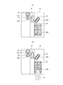
- FIG. 4A is a schematic diagram illustrating an example of an image presented to the presentation unit according to the embodiment of the present invention
- FIG. 4B illustrates an example of an operation on the image presented to the presentation unit according to the embodiment of the present invention.
- FIG. 4C is a schematic diagram illustrating another example of an operation on an image presented to the presentation unit according to the embodiment of the present invention.
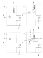
- FIG. 7A is a schematic diagram illustrating an example of an image presented in the presentation unit according to the first modification of the embodiment of the present invention
- FIG. 7B relates to the first modification of the embodiment of the present invention.
- FIG. 8A is a schematic diagram illustrating an example of an image presented in the presentation unit according to the second modification of the embodiment of the present invention
- FIG. 8B relates to the second modification of the embodiment of the present invention.
- FIG. 9A is a schematic diagram illustrating an example of an image presented in the presentation unit according to the third modification example of the embodiment of the present invention
- FIG. 9B relates to the third modification example of the embodiment of the present invention.
- FIG. 10A is a schematic diagram illustrating an example of map data stored in a storage device according to a fourth modification of the embodiment of the present invention
- FIG. 10B illustrates a fourth modification of the embodiment of the present invention
- FIG. 10C is a schematic diagram illustrating an example of an operation on the detection result of the ambient condition sensor according to the fourth modification of the embodiment of the present invention.
- FIG. 10D is a schematic diagram illustrating an example of correction of the detection result of the ambient state sensor according to the fourth modification example of the embodiment of the present invention.
- FIG. 11A is a schematic diagram illustrating an example of an image presented in the presentation unit according to the fifth modification of the embodiment of the present invention, and FIG. 11B relates to the fifth modification of the embodiment of the present invention. It is the schematic which shows an example of operation with respect to the image shown to a presentation unit.
- FIG. 12A is a schematic diagram illustrating an example of an image presented in the presentation unit according to the sixth modification of the embodiment of the present invention, and FIG. 12B relates to the sixth modification of the embodiment of the present invention. It is the schematic which shows an example of operation with respect to the image shown to a presentation unit.
- the self-position estimation device stores a surrounding situation of a parking target position in a storage device, and can be used in a parking assistance device that performs automatic parking using the stored surrounding situation. This is a device for estimating the position (self-position) of the host vehicle in the surrounding situation.
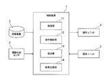
- the self-position estimation apparatus can be mounted on a vehicle (hereinafter, the vehicle equipped with the self-position estimation apparatus according to the embodiment of the present invention is referred to as “own vehicle”). As shown in FIG. 1, the self-position estimation apparatus according to the embodiment of the present invention includes a control device (controller) 1, a storage device 2, an ambient condition sensor 3, a presentation unit 4, and an operation unit (interface) 5.
- the storage device 2 includes a semiconductor storage device, a magnetic storage device, an optical storage device, or the like, and can constitute a register, a cache memory, a main storage device, or the like.
- storage device 2 memorize
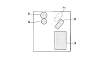
- the storage device 2 stores map data as an example of the surrounding situation of the parking target position P1.
- FIG. 2 illustrates the case where the map data is a bird's-eye view image and a computer graphics (CG) image, the present invention is not limited to this.
- the map data indicates the positional relationship between the targets 21, 22, 23, and 24 existing around the parking target position P1.
- the targets 21, 22, 23, and 24 include signs, utility poles, walls, trees, stationary solid objects (obstacles) such as other vehicles that are parked, white lines on the road, parking frames, and the like.
- the range of the map data is not particularly limited, and may be a range in which automatic parking at the parking target position P1 is possible.
- the surrounding situation of the parking target position such as map data stored in the storage device 2 is obtained as a learning result by detecting the surrounding situation of the parking target position by the surrounding situation sensor 3 when parking once or a plurality of times. can get.
- “one-time parking” includes, for example, an operation until the host vehicle reaches the parking target position. Further, in the “one-time parking”, even if the host vehicle does not reach the parking target position, if the surrounding situation of the parking target position can be detected by the surrounding situation sensor 3, the own vehicle is set to the parking target position.
- movement until the own vehicle turns around the parking target position are included.
- multiple parking means repeating one parking, but the timing of repeating is not particularly limited.
- the second parking may be performed immediately after the first parking. You may park the second time the day after parking.
- the multiple parkings may be the same parking operations or different parking operations.
- the operation until the first parking of the two parkings reaches the parking target position, and the second parking may be an operation of traveling around the parking target position.
- the surrounding situation of the parking target position stored in the storage device 2 can be referred to in the next and subsequent parking.
- the timing of “parking after the next time” is not particularly limited, and includes, for example, immediately after learning the surrounding situation of the parking target position or after the day after learning the surrounding situation of the parking target position.
- the parking operation of “parking after the next time” includes the operation of the vehicle targeting the parking target position such as the operation of the host vehicle reaching the parking target position and the operation of traveling around the parking target position.
- the ambient condition sensor 3 shown in FIG. 1 detects the ambient condition of the host vehicle including the front, side, and rear of the host vehicle.
- the ambient condition sensor 3 for example, a laser radar, a millimeter wave radar, a camera, a laser range finder (LRF), or the like can be used.
- the number, type, and arrangement position of the ambient condition sensors 3 are not particularly limited, and for example, a plurality of ambient condition sensors 3 may be installed in front, side, and rear of the host vehicle.
- FIG. 3 shows an example of the surrounding situation (point cloud data) of the host vehicle detected by the surrounding situation sensor 3, and the point cloud 26 in FIG. 3 shows the edge position of the target (obstacle).
- the range of the point cloud data shown in FIG. 3 is substantially the same as the range of the map data shown in FIG.
- the range of the point cloud data shown in FIG. 3 may be narrower than the range of the map data shown in FIG. 2, or may be wider than the range of the map data shown in FIG.
- a display such as a liquid crystal display can be used as the presentation unit 4 shown in FIG.
- the presentation unit 4 is installed at a position that can be easily seen by the passenger such as an instrument panel in the vehicle interior.
- the operation unit 5 receives an operation from a passenger.
- the operation unit 5 may be a touch panel, a button, or a switch of the presentation unit 4, or may be a button, a switch, or the like provided on the center console or the like separately from the presentation unit 4.
- the control device 1 is a controller such as an electronic control unit (ECU), for example, and can be constituted by a computer including a central processing unit (CPU), a processor equivalent to the computer, or the like.
- the control device 1 may have a programmable logic device (PLD) such as a field programmable gate array (FPGA), a functional logic circuit set in a general-purpose semiconductor integrated circuit, etc. It doesn't matter.
- PLD programmable logic device
- FPGA field programmable gate array
- the control device 1 functionally includes an estimation unit 11, a presentation control unit 12, a setting unit 13, and a parking support unit 14.
- the estimation unit 11 collates (matches) the position of the host vehicle and the position of the target in the surrounding state of the own vehicle detected by the surrounding state sensor 3 with the map data stored in the storage device 2, thereby Estimate the position of the vehicle (self-position) and the position of the target on the data.
- the estimation unit 11 superimposes the map data shown in FIG. 2 and the surrounding situation of the host vehicle shown in FIG. 3 so that the corresponding targets 21, 22, 23, and 24 match.
- the position (self-position) of the own vehicle on map data is estimated based on the surrounding condition of the own vehicle shown in FIG. 3, and the relative positional relationship with the own vehicle.
- the surroundings of the vehicle and the map data cannot be accurately matched, and the position of the vehicle on the map data May not be accurately estimated.
- the presentation control unit 12 determines whether or not a predetermined specific target (for example, a point group corresponding to the target 24 in FIG. 2) has been detected as the surrounding state of the host vehicle detected by the surrounding state sensor 3. Judgment is made, and the judgment result is presented to the occupant by voice or display.
- the specific target is a target that makes it easy to estimate the position of the host vehicle due to its position and shape, and can be set as appropriate. When it is determined that a specific target has been detected, the occupant knows that the environment is easy to estimate the position of the vehicle by presenting to the occupant that the specific target has been detected. it can.
- the presentation control unit 12 may determine whether or not all the plurality of targets are detected, and whether or not a predetermined number or more of the plurality of targets are detected. May be determined.
- the presentation control unit 12 collates (matches) the map data stored in the storage device 2 with the surrounding situation (point cloud data) of the host vehicle detected by the surrounding situation sensor 3.
- I1 is presented to the presentation unit 4.
- the presentation unit 4 may present the entire map data or a part of the map data. When a part of the map data is presented to the presentation unit 4, the map data may be scrollable up and down and left and right. Similarly, the entire surrounding situation of the host vehicle detected by the surrounding situation sensor 3 may be presented to the presentation unit 4 or a part of the surrounding situation may be presented. When a part of the surrounding situation is presented to the presentation unit 4, the surrounding situation may be scrollable up, down, left, and right.
- map data presented to the presentation unit 4 and the surrounding situation may have the same size or different sizes.
- the entire surrounding situation may be superimposed on a part of the map data presented to the presentation unit 4.
- the entire map data may be superimposed on a part of the surrounding situation presented to the presentation unit 4.
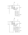
- the presentation control unit 12 further presents a simulated vehicle (icon) 27 at the position of the host vehicle on the map data estimated by the estimation unit 11, as shown in FIG. 4A.
- crew should just identify that it is the position of the own vehicle on the map data estimated by the estimation part 11, you may show not only the simulation vehicle 27 but graphics, such as a rectangle, to the presentation unit 4.
- the presentation control unit 12 further presents text information and voice information such as “Please align the map data and the surrounding situation” or “Please align the map data and the icon” to the occupant. By doing so, the passenger may be requested to operate.
- the operation unit 5 sets the positional relationship between the map data and at least one of the positions of the target vehicle existing around the host vehicle. Accept (adjust) the operation from the passenger.
- the operation unit 5 is a touch panel, as shown in FIG. 4B, the occupant touches and scrolls the target 24 on the map data with the finger 31 in the direction of the arrow (downward), thereby causing the target 21. , 22, 23, 24, the entire map data is shifted downward.
- the point groups 26 corresponding to the targets 21, 22, 23, 24 on the map data it is possible to match the point groups 26 corresponding to the targets 21, 22, 23, 24 on the map data.
- the entire map data can be rotated by operations such as rotating two fingers by touching any position on the map data. You may let them.
- the occupant shifts the entire situation of the simulated vehicle 27 and the own vehicle upward by touch-scrolling the simulated vehicle 27 with the finger 31 in the direction of the arrow (upward). Also good. Since the position of the own vehicle corresponding to the position of the simulated vehicle 27 is obtained from the relative positional relationship with the surrounding situation of the own vehicle, the surrounding situation of the own vehicle moves as the simulated vehicle 27 moves. As a result, it is possible to match the point groups 26 corresponding to the targets 21, 22, 23, 24 on the map data. Further, the occupant may shift the simulated vehicle 27 and the entire surrounding situation of the host vehicle by touch-scrolling an arbitrary position of the point cloud 26 that is the surrounding situation of the own vehicle with the finger 31.
- the occupant may directly set the position of the host vehicle on the map data by touching the position of the host vehicle on the map data instead of touch-scrolling the simulated vehicle 27.
- the operation unit 5 is not a touch panel but a button, the simulated vehicle 27 may be moved by pressing the button.
- the operation method for setting the positional relationship between the map data and the surrounding situation of the host vehicle or the host vehicle is not particularly limited, and various methods can be adopted.
- the operation method for setting the surrounding situation of the host vehicle or the positional relationship with the host vehicle may be set in advance, or may be appropriately selected by the operation of the operation unit 5.
- the setting unit 13 sets at least one of the position of the own vehicle and the position of the target on the map data based on the map data and operation information for setting the positional relationship between the surrounding situation of the own vehicle or the own vehicle. For example, as illustrated in FIG. 4B, when the occupant performs an operation of setting the positional relationship between the map data and the surrounding situation of the host vehicle, the setting unit 13 sets the surrounding state of the own vehicle by the estimating unit 11. The result of matching (matching) with the map data is corrected to the positional relationship corresponding to FIG. 4B. The setting unit 13 further corrects the position of the host vehicle estimated by the estimation unit 11 based on the corrected result of matching (matching). As shown in FIG. 4C, when the occupant executes an operation for setting the positional relationship between the map data and the host vehicle, the setting unit 13 sets the host vehicle on the map data estimated by the estimation unit 11. Is corrected to a position corresponding to FIG. 4C.
- the setting unit 13 detects the map of the detected target based on the relative positional relationship between the vehicle and the target.
- the positional relationship on the data may be set.
- the setting unit 13 detects the map of the detected own vehicle based on the relative positional relationship between the own vehicle and the target. The positional relationship on the data may be set.
- the parking support unit 14 initializes the position of the host vehicle on the map data set by the setting unit 13 as a parking start position when performing automatic parking. And the parking assistance part 14 outputs a control signal with respect to the various actuators mounted in the own vehicle so that it may park automatically from the parking start position to the parking target position P1.
- the parking support unit 14 may be provided as a parking support device separately from the control device 1.
- step S11 the current position of the host vehicle is initialized as a parking start position.
- step S12 the vehicle is parked from the parking start position to the parking target position P1 while the surrounding situation sensor 3 detects the surrounding situation of the host vehicle.
- step S13 it is determined whether or not parking is completed at the parking target position P1 and detection of the surrounding situation is completed. Until it is determined that the detection of the surrounding situation is completed, the detection of the surrounding situation of the host vehicle is continued by the surrounding situation sensor 3, and when it is determined that the detection of the surrounding situation is completed, the process proceeds to step S14.
- step S14 map data is generated using the surrounding situation detected by the surrounding situation sensor 3, and the generated map data is stored in the storage device 2. Note that map data obtained by integrating the map data obtained each time by executing the process of the flowchart of FIG. 5 a plurality of times may be employed.
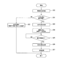
- step S20 the estimation unit 11 estimates the current position of the host vehicle based on a global positioning system (GPS) signal or the like. Based on the estimated current position of the host vehicle, the estimation unit 11 uses map data around the parking target position P1 for use in automatic parking, as shown in FIG. 2, from data stored in the storage device 2. Is identified.
- the ambient condition sensor 3 detects the ambient condition of the host vehicle as shown in FIG.
- step S21 the estimation unit 11 determines whether or not a specific target (for example, the target 24) predetermined as the surrounding state of the host vehicle detected by the surrounding state sensor 3 has been detected. It is determined whether the position of the vehicle can be estimated (or whether it is easy to estimate). If a specific target is not detected and it is determined that the position of the host vehicle cannot be estimated (or is difficult to estimate), the process proceeds to step S22, and the position of the host vehicle cannot be estimated ( Or it is difficult to estimate) to the occupant by voice or presentation, and the process is completed.
- a specific target for example, the target 24
- step S21 if it is determined in step S21 that a specific target is detected as the surrounding state of the host vehicle detected by the surrounding state sensor 3 and the position of the host vehicle can be estimated (or easily estimated)
- step S23 in which the estimation unit 11 presents to the occupant by voice, presentation, etc. that the position of the host vehicle can be estimated (or easily estimated).
- step S24 the presentation control unit 12 causes the presentation unit 4 to present an image I1 that is a result of matching (matching) between the map data and the surrounding situation of the host vehicle. Further, the presentation control unit 12 presents the simulated vehicle 27 at the position of the host vehicle estimated by the estimation unit 11.
- the operation unit 5 receives an operation for setting the positional relationship between the map data and at least one of the host vehicle and the target. The occupant operates the operation unit 5 so as to set the correct positional relationship between the map data and the target or the simulated vehicle 27 (correct the positional relationship shift).
- the presentation control unit 12 changes the presentation of the presentation unit 4 as illustrated in FIG. 4B or FIG. 4C according to the operation information of the occupant.
- step S25 the presentation control unit 12 determines whether an occupant's operation has been received via the operation unit 5.
- the presentation unit 4 continues to be presented until it is determined that an occupant's operation has been received. If it is determined that an occupant's operation has been received, the process proceeds to step S26.
- step S ⁇ b> 26 the setting unit 13 corrects the result of collation between the surrounding situation of the host vehicle and the map data by the estimation unit 11, that is, the position of the host vehicle or the target position on the map data, based on the occupant operation information. To do.
- step S27 the parking support unit 14 initializes the position of the host vehicle on the map data set by the setting unit 13 as a parking start position.
- the parking assistance part 14 outputs a control signal with respect to the various actuators mounted in the own vehicle so that it may park automatically from a parking start position to a parking target position using map data.
- the self-position estimation program according to the embodiment of the present invention causes the computer constituting the control device 1 to execute the procedure of the self-position estimation method shown in FIG.
- the self-position estimation program according to the embodiment of the present invention can be stored in the storage device 2, for example.
- the presentation control unit When the automatic parking is performed using the surrounding situation of the parking target position stored in the storage device 2 when parking at the parking target position, the presentation control unit The surrounding situation (map data) in which 12 is stored is presented to the presentation unit 4. And the operation unit 5 receives operation which sets the positional relationship of the memorize
- the accuracy of the estimation of the parking start position is important, but since the parking start position can be estimated with high accuracy, the route from the parking start position to the parking target position can be accurately calculated, It is possible to park at the parking target position with high accuracy.
- the estimation unit 11 estimates the position of the host vehicle or the target in the surrounding situation (map data) of the stored parking target position based on the surrounding situation of the own vehicle detected by the surrounding situation sensor 3.
- the presentation control unit 12 presents the position or target of the host vehicle in the stored surrounding situation to the presentation unit 4 and presents the position or target of the subject vehicle in the detected surrounding situation to the presentation unit 4.
- the operation unit 5 receives an operation for associating the position or target of the host vehicle in the stored surrounding situation with the position or target of the host vehicle in the detected surrounding situation.
- the occupant points the positions of the targets 21, 22, 23, and 24 on the map data and the corresponding surrounding situation (point cloud data) of the subject vehicle while visually confirming the presentation of the presentation unit 4. It is possible to perform an operation of setting so that the group 26 matches.
- the presentation unit 4 may present the map data that is the bird's-eye view image.
- the surrounding state of the host vehicle detected by the surrounding state sensor 3 may be presented to the presentation unit 4 as an overhead image. In this case, the occupant can accurately grasp the relative positional relationship between the host vehicle and the surrounding situation of the host vehicle.
- the estimation unit 11 determines whether or not a specific target is detected as the surrounding state of the host vehicle detected by the surrounding state sensor 3, and if a specific target is detected, a specific target is detected. Present the detection of the target to the occupant. As a result, a specific target can be detected, and the occupant can easily grasp that the environment is easy to estimate the position of the own vehicle from the relative positional relationship between the specific target and the own vehicle. Can be made. On the other hand, when the specific target is not detected, the passenger is notified that the specific target is not detected. Thereby, a specific target cannot be detected, and it is possible for the occupant to easily grasp whether the environment is difficult to estimate the position of the host vehicle.
- the estimation unit 11 detects (estimates) the relative positional relationship between the host vehicle and the target in the detected surrounding situation based on the surrounding situation of the own vehicle detected by the surrounding situation sensor 3. Then, when the positional relationship in the stored ambient situation of any of the detected own vehicle or target is set via the operation unit 5, based on the relative positional relationship between the own vehicle and the target, The positional relationship in the other stored surrounding situation of the detected own vehicle or target is set. Thereby, the position of the own vehicle and the position of the target in the stored surrounding situation can be accurately estimated using the relative positional relationship between the own vehicle and the target.
- FIG. 4A an image I1 in which the map data stored in the storage device 2 and the surrounding situation of the host vehicle detected by the surrounding situation sensor 3 are superimposed is presented to the presentation unit 4.
- the surrounding state of the host vehicle detected by the surrounding state sensor 3 is not presented and stored in the storage device 2.
- the map data includes targets 21, 22, 23, and 24.
- the simulated vehicle 27 is presented at the position of the host vehicle on the map data estimated by the estimation unit 11.
- the occupant visually recognizes the surrounding situation of the own vehicle and grasps the correspondence between the actual surrounding situation of the own vehicle and the presented map data.
- the operation unit 5 is a touch panel
- the occupant drags the simulated vehicle 27 with the finger 31 in the arrow direction (downward) as shown in FIG. 7B, for example, in the actual surrounding situation of the own vehicle. Drop at a location on the map data that corresponds to the location of your vehicle.
- the positional relationship between the map data and the host vehicle is set by moving the simulated vehicle 27 with respect to the map data.
- the occupant touches and scrolls any of the targets 21, 22, 23, and 24 on the map data to move the entire map data including the targets 21, 22, 23, and 24 with respect to the simulated vehicle 27.
- the setting unit 13 corrects the position of the host vehicle on the map data estimated by the estimation unit 11 to a position corresponding to FIG.
- FIG. 7A illustrates the case where the simulated vehicle 27 is presented on the map data
- the simulated vehicle 27 may not be presented on the map data.
- the occupant may set the position of the host vehicle on the map data by touching a position corresponding to the position of the host vehicle on the map data.
- the surrounding situation sensor 3 does not need to detect the surrounding situation of the own vehicle, and the estimation unit 11 estimates the position of the own vehicle on the map data. It does not have to be.
- the occupant can use the map data and the own vehicle.
- the correct positional relationship with can be set.
- the setting part 13 can estimate the position of the own vehicle on map data with a sufficient precision by setting the position of the own vehicle on map data based on a passenger
- the occupant touch-scrolls the target 24 on the map data with the finger 31 in the arrow direction (downward), and includes map data including the targets 21, 22, 23, and 24.
- map data and the surrounding situation (point cloud data) of the host vehicle are matched.
- the setting unit 13 sets the position of the host vehicle on the map data based on the occupant's operation information.
- the map data stored in the storage device 2 and the surrounding situation of the host vehicle detected by the surrounding situation sensor 3 are presented.
- the occupant can set the positional relationship between the map data and the surrounding situation of the host vehicle.
- the setting part 13 can estimate the position of the own vehicle on map data with a sufficient precision by setting the position of the own vehicle on map data based on a passenger
- the presentation unit 4 presents an image I2 in which the map data stored in the storage device 2 and the camera image as the surrounding situation of the host vehicle detected by the surrounding situation sensor 3 are superimposed.
- the camera image includes targets 21a, 22a, 23a, and 24a, and these targets 21a, 22a, 23a, and 24a correspond to the targets 21, 22, 23, and 24 of the map data stored in the storage device 2.
- the occupant touches and scrolls the target 24 on the map data in the arrow direction (downward) with the finger 31 to include the map data 21, 22, 23, and 24. Move the whole down and match the map data to the camera image.
- the occupant moves the entire camera image including the targets 21a, 22a, 23a, and 24a by touch-scrolling any of the targets 21a, 22a, 23a, and 24a of the camera image, and converts the camera image into the map data. May be matched.
- the occupant by presenting a camera image as the surrounding situation of the host vehicle detected by the surrounding situation sensor 3, the occupant can compare with the case where a CG image is presented. In addition, it becomes easy to intuitively grasp the positional relationship between the map data and the surrounding situation of the host vehicle.
- FIG. 10A is an image I3 of the map data stored in the storage device 2, and the targets 41 and 42 exist.
- FIG. 10B is an image I4 of the surrounding situation of the host vehicle detected by the surrounding situation sensor 3, and includes targets 41a and 42a.
- the targets 41a and 42a correspond to the targets 41 and 42 of the map data shown in FIG. 10A, but the position of the target 41a is misdetected by deviating from the actual position.
- the simulated vehicle 43 is presented at the position of the host vehicle estimated by the estimation unit 11.
- the presentation control unit 12 causes the presentation unit 4 to present the map data image I3 shown in FIG. 10A and the surrounding image I4 of the host vehicle shown in FIG. 10B side by side.
- the occupant sets the position of the target 41a by dragging the target 41a in the surroundings of the host vehicle with the finger 31 in the direction of the arrow (right direction) and dropping it at the correct position, as shown in FIG. 10C. Perform the operation.
- the setting unit 13 sets (corrects) the position of the target 41a in the surrounding state of the host vehicle detected by the surrounding state sensor 3 based on the operation information of the occupant.
- the setting unit 13 further sets (corrects) the position of the host vehicle as shown in FIG. 10D based on the relative positional relationship between the corrected targets 41a and 42a and the host vehicle.
- the position of the target of the surrounding situation of the host vehicle detected by the surrounding situation sensor 3 can be individually set, and the set surrounding situation of the own vehicle The position of the host vehicle can be set based on the above.
- the left side of FIG. 11A is an image I5 of map data stored in the storage device 2, and includes targets 21, 22, 23, and 24.
- map data image I5 a simulated vehicle representing the position of the host vehicle on the map data estimated by the estimation unit 11 may be presented.
- the right side of FIG. 11A is a CG image I6 of the surrounding situation of the host vehicle detected by the surrounding situation sensor 3, and includes targets 21a, 22a, 23a, and 24a.
- the CG image I6 of the surrounding situation of the host vehicle can be generated based on, for example, point cloud data or a camera image.
- the simulated vehicle 27 is presented at the position of the host vehicle estimated by the estimating unit 11 in the CG image I6 of the surrounding situation of the host vehicle.
- the occupant drags the simulated vehicle 27 in the image I6 of the surrounding situation of the right vehicle, moves as indicated by the arrow, and drops it at a position on the image I5 of the left map data. By doing so, the position of the own vehicle on map data is set.
- the setting unit 13 sets the position where the simulated vehicle 27 is dragged on the map data as the position of the host vehicle based on the occupant's operation information.
- the occupant drags the target 22a in the image I6 of the surrounding situation of the right vehicle, moves as shown by the arrow, and moves the target 22 in the image I5 of the left map data. It may be set that the target 22a of the surrounding situation of the host vehicle and the target 22 of the map data coincide with each other by dropping at the position.
- the setting unit 13 collates the map data with the surrounding situation of the host vehicle so that the position of the target 22 of the map data matches the position of the target 22a of the surrounding situation of the own vehicle. (Matching) results are corrected.
- the setting unit 13 further corrects the position of the host vehicle on the map data estimated by the estimation unit 11 based on the corrected (matching) result of the map data and the surrounding situation of the host vehicle.
- the occupant can map The positional relationship between the data and the surrounding situation of the host vehicle or the host vehicle can be set. Then, the setting unit 13 can accurately estimate the position of the host vehicle on the map data by correcting the position of the host vehicle on the map data estimated by the estimation unit 11 based on the occupant's operation information. Become.
- the map data stored in the storage device 2 includes a cross mark 52 corresponding to the sign 51.
- the surrounding situation of the host vehicle detected by the surrounding situation sensor 3 includes a parking frame and a sign 51.
- the estimation unit 11 collates (matches) the map data stored in the storage device 2 with the surrounding state of the host vehicle detected by the surrounding state sensor 3, a puddle or the like detected by the surrounding state sensor 3 is displayed.
- the cross mark 52 of the map data that is erroneously recognized as the sign 51 and stored in the storage device 2 is aligned with the position of the sign 51 relatively shifted.
- the occupant sets the cross mark 52 and the sign 51 to coincide by dragging the cross mark 52 of the map data with a finger and dropping it at the position of the sign 51 as shown in FIG. 12B.
- the setting unit 13 corrects the matching result of the map data and the surrounding situation of the host vehicle so that the position of the cross mark 52 of the map data matches the position of the sign 51 based on the operation information of the occupant. .
- the setting unit 13 further corrects the position of the host vehicle on the map data estimated by the estimation unit 11 based on a result of matching (matching) between the corrected map data and the surrounding situation of the host vehicle.
- the case where the front image I7 in which the map data stored in the storage device 2 and the surrounding situation of the host vehicle detected by the surrounding situation sensor 3 are superimposed is presented.
- the occupant can set the positional relationship between the map data and the surrounding situation of the host vehicle.
- the setting unit 13 can accurately estimate the position of the host vehicle on the map data by correcting the position of the host vehicle on the map data estimated by the estimation unit 11 based on the occupant's operation information. Become.
- map data is presented as a CG image
- the surrounding situation of the host vehicle detected by the surrounding situation sensor 3 is presented as point cloud data.
- the present invention is not limited to this.
- the map data may be presented as a camera image, and the surrounding situation of the host vehicle detected by the surrounding situation sensor 3 may be presented as a camera image.
- the map data may be presented as a camera image, and the surrounding situation of the host vehicle detected by the surrounding situation sensor 3 may be presented as a CG image.
- the map data may be presented as a CG image, and the surrounding situation of the host vehicle detected by the surrounding situation sensor 3 may be presented as a camera image.
- the presentation unit 4 is a display
- the presentation unit 4 may be a device other than the display.
- the presentation unit 4 when the presentation unit 4 is a speaker, the presentation unit 4 outputs a sound that describes the surrounding situation of the stored parking target position and the surrounding situation of the host vehicle detected by the surrounding situation sensor 3.
- the stored surrounding situation of the parking target position and the surrounding situation of the host vehicle detected by the surrounding situation sensor 3 can be presented to the occupant.
Landscapes
- Engineering & Computer Science (AREA)
- Mechanical Engineering (AREA)
- Transportation (AREA)
- Combustion & Propulsion (AREA)
- Chemical & Material Sciences (AREA)
- Automation & Control Theory (AREA)
- Physics & Mathematics (AREA)
- General Physics & Mathematics (AREA)
- Human Computer Interaction (AREA)
- Mathematical Physics (AREA)
- Computer Vision & Pattern Recognition (AREA)
- Theoretical Computer Science (AREA)
- Traffic Control Systems (AREA)
- Navigation (AREA)
- Radar Systems Or Details Thereof (AREA)
- Control Of Driving Devices And Active Controlling Of Vehicle (AREA)
Abstract
Description
本発明の実施形態に係る自己位置推定装置は、駐車目標位置の周囲状況を記憶装置に記憶し、記憶された周囲状況を用いて自動駐車を実行する駐車支援装置で利用可能な、記憶された周囲状況における自車両の位置(自己位置)等を推定するための装置である。本発明の実施形態に係る自己位置推定装置は、車両に搭載可能である(以下、本発明の実施形態に係る自己位置推定装置が搭載された車両を「自車両」と称する)。本発明の実施形態に係る自己位置推定装置は、図1に示すように、制御装置(コントローラ)1、記憶装置2、周囲状況センサ3、提示ユニット4及び操作ユニット(インターフェース)5を備える。
ここで、図5のフローチャートを参照して、記憶装置2に記憶されている地図データの生成方法の一例を説明する。ステップS11において、自車両の現在位置を駐車開始位置として初期化する。ステップS12において、周囲状況センサ3により自車両の周囲状況を検出しながら、駐車開始位置から駐車目標位置P1へ駐車する。ステップS13において、駐車目標位置P1へ駐車が完了し、周囲状況の検出が完了したか否かを判定する。周囲状況の検出が完了したと判定されるまで、周囲状況センサ3により自車両の周囲状況の検出を継続し、周囲状況の検出が完了したと判定された場合にステップS14に移行する。ステップS14において、周囲状況センサ3により検出された周囲状況を用いて地図データを生成し、生成した地図データを記憶装置2に記憶させる。なお、図5のフローチャートの処理を複数回実行して、各回で得られた地図データを統合した地図データを採用してもよい。
次に、図6のフローチャートを参照しながら、本発明の実施形態に係る自己位置推定方法の一例を説明する。
本発明の実施形態では、図4Aに示すように、記憶装置2に記憶された地図データと、周囲状況センサ3により検出された自車両の周囲状況とを重畳した画像I1を提示ユニット4に提示する場合を説明した。これに対して、本発明の実施形態の第1の変形例では、図7Aに示すように、周囲状況センサ3により検出された自車両の周囲状況を提示せずに、記憶装置2に記憶された地図データのみを提示する点が、本発明の実施形態と異なる。地図データは、物標21,22,23,24を含む。更に、図7Aに示すように、推定部11により推定された地図データ上の自車両の位置に模擬車両27を提示する。
本発明の実施形態では、図4Aに示すように、提示ユニット4に、記憶装置2に記憶された地図データと、周囲状況センサ3により検出された自車両の周囲状況とを重畳した画像I1を提示するとともに、模擬車両27を提示する場合を説明した。これに対して、本発明の実施形態の第2の変形例では、図8Aに示すように、提示ユニット4に、地図データと自車両の周囲状況とを重畳した画像I1を提示する点は本発明の実施形態と同様であるが、模擬車両27を提示しない点が、本発明の実施形態と異なる。
本発明の実施形態では、図4Aに示すように、周囲状況センサ3により検出された自車両の周囲状況として点群データを用いる場合を説明した。これに対して、本発明の実施形態の第3の変形例では、図9Aに示すように、周囲状況センサ3により検出された自車両の周囲状況としてカメラ画像を用いる点が、本発明の実施形態と異なる。
本発明の実施形態の第4の変形例として、周囲状況センサ3により検出された自車両の周囲状況の物標の位置を個別に設定する場合を説明する。図10Aは、記憶装置2に記憶された地図データの画像I3であり、物標41,42が存在する。図10Bは、周囲状況センサ3により検出された自車両の周囲状況の画像I4であり、物標41a,42aを含む。物標41a,42aは、図10Aに示した地図データの物標41,42に対応するが、物標41aの位置が実際の位置からずれて誤検出されている。図10Bには、推定部11により推定された自車両の位置に模擬車両43が提示されている。
本発明の実施形態では、図4Aに示すように、記憶装置2に記憶された地図データと、周囲状況センサ3により検出された自車両の周囲状況とを重畳した画像I1を提示ユニット4に提示する場合を説明した。これに対して、本発明の実施形態の第5の変形例では、図11Aに示すように、地図データと自車両の周囲状況とを重畳させずに並べて提示する点が、本発明の実施形態と異なる。
本発明の実施形態では、図4Aに示すように、記憶装置2に記憶された地図データと、周囲状況センサ3により検出された自車両の周囲状況とを重畳した俯瞰画像I1を提示ユニット4に提示する場合を説明した。これに対して、本発明の実施形態の第6の変形例では、図12Aに示すように、記憶装置2に記憶された地図データと、周囲状況センサ3により検出された自車両の周囲状況とを重畳した前方画像I7を提示する点が、本発明の実施形態と異なる。
上記のように、本発明は実施形態によって記載したが、この開示の一部をなす論述及び図面は本発明を限定するものであると理解すべきではない。この開示から当業者には様々な代替実施の形態、実施例及び運用技術が明らかとなろう。
2…記憶装置
3…周囲状況センサ
4…提示ユニット
5…操作ユニット
11…推定部
12…提示制御部
13…設定部
14…駐車支援部
Claims (6)
- 駐車目標位置への駐車に際し、前記駐車目標位置の周囲状況を記憶装置に記憶し、前記記憶された周囲状況を用いて自動駐車を実行する駐車支援装置の自己位置推定方法において、
前記記憶された周囲状況を提示するステップと、
前記記憶された周囲状況と、自車両及び前記自車両の周囲に存在する物標と、の位置関係を設定する操作を受け付けるステップと、
前記操作に基づいて、前記記憶された周囲状況における前記自車両の位置又は前記物標の位置を設定するステップ
とを含むことを特徴とする自己位置推定方法。 - 前記自車両の周囲状況を検出するステップと、
前記検出された周囲状況に基づいて、前記記憶された周囲状況における前記自車両又は前記物標の位置を推定するステップ
とを更に含み、
前記提示するステップは、前記記憶された周囲状況における前記自車両の位置又は前記物標を提示するとともに、前記検出された周囲状況における前記自車両の位置又は前記物標を提示し、
前記受け付けるステップは、前記記憶された周囲状況における前記自車両の位置又は前記物標と、前記検出された周囲状況における前記自車両の位置又は前記物標と、を対応付ける操作を受け付けることを特徴とする請求項1に記載の自己位置推定方法。 - 前記記憶された周囲状況又は前記検出された周囲状況を俯瞰画像で提示することを特徴とする請求項2に記載の自己位置推定方法。
- 前記検出された周囲状況として予め定めた特定の物標が検出されたか否かを判定するステップと、
前記特定の物標が検出された場合に、前記特定の物標の検出を乗員に対して提示するステップ
とを更に含むことを特徴とする請求項2又は3に記載の自己位置推定方法。 - 前記自車両の周囲状況により、検出した周囲状況における前記自車両と物標の相対位置関係を検出するステップと、
をさらに含み、
前記自車両の位置又は前記物標の位置を設定するステップは、検出した自車両又は物標の内の何れかの前記記憶された周囲状況における位置関係が設定された場合に、前記相対位置関係に基づいて、検出した自車両又は物標の内のもう一方の前記記憶された周囲状況における位置関係を設定する
ことを特徴とする請求項2~4のいずれか1項に記載の自己位置推定方法。 - 駐車目標位置への駐車に際し、前記駐車目標位置の周囲状況を記憶装置に記憶し、前記記憶された周囲状況を用いて自動駐車を実行する駐車支援装置の自己位置推定装置において、
前記記憶された周囲状況を提示する提示ユニットと、
前記記憶された周囲状況が提示された時に、前記記憶された周囲状況と、自車両又は前記自車両の周囲に存在する物標と、の位置関係を設定する操作を受け付けるインターフェースと、
前記操作に基づいて、前記記憶された周囲状況における前記自車両の位置又は前記物標の位置を設定するコントローラと、
を備えることを特徴とする自己位置推定装置。
Priority Applications (11)
| Application Number | Priority Date | Filing Date | Title |
|---|---|---|---|
| EP16918587.3A EP3527456A4 (en) | 2016-10-13 | 2016-10-13 | HOST POSITION ASSESSMENT METHOD AND HOST POSITION ASSESSMENT DEVICE |
| CA3041177A CA3041177C (en) | 2016-10-13 | 2016-10-13 | Self position estimation method and self position estimation device |
| JP2018544647A JP6693570B2 (ja) | 2016-10-13 | 2016-10-13 | 自己位置推定方法及び自己位置推定装置 |
| CN201680090085.4A CN109843688B (zh) | 2016-10-13 | 2016-10-13 | 自身位置推定方法及自身位置推定装置 |
| RU2019112826A RU2711245C1 (ru) | 2016-10-13 | 2016-10-13 | Способ оценки собственного положения и устройство оценки собственного положения |
| KR1020197011784A KR102233901B1 (ko) | 2016-10-13 | 2016-10-13 | 자기 위치 추정 방법 및 자기 위치 추정 장치 |
| US16/340,972 US11027725B2 (en) | 2016-10-13 | 2016-10-13 | Self position estimation method and self position estimation device |
| BR112019007386-8A BR112019007386B1 (pt) | 2016-10-13 | 2016-10-13 | Método de estimativa de autoposicionamento e dispositivo de estimativa de autoposicionamento |
| MX2019004336A MX375822B (es) | 2016-10-13 | 2016-10-13 | Método de estimación de la posición propia y dispositivo de estimación de la posición propia. |
| PCT/JP2016/080387 WO2018070022A1 (ja) | 2016-10-13 | 2016-10-13 | 自己位置推定方法及び自己位置推定装置 |
| MYPI2019001979A MY183913A (en) | 2016-10-13 | 2016-10-13 | Self position estimation method and self position estimation device |
Applications Claiming Priority (1)
| Application Number | Priority Date | Filing Date | Title |
|---|---|---|---|
| PCT/JP2016/080387 WO2018070022A1 (ja) | 2016-10-13 | 2016-10-13 | 自己位置推定方法及び自己位置推定装置 |
Publications (1)
| Publication Number | Publication Date |
|---|---|
| WO2018070022A1 true WO2018070022A1 (ja) | 2018-04-19 |
Family
ID=61905352
Family Applications (1)
| Application Number | Title | Priority Date | Filing Date |
|---|---|---|---|
| PCT/JP2016/080387 Ceased WO2018070022A1 (ja) | 2016-10-13 | 2016-10-13 | 自己位置推定方法及び自己位置推定装置 |
Country Status (11)
| Country | Link |
|---|---|
| US (1) | US11027725B2 (ja) |
| EP (1) | EP3527456A4 (ja) |
| JP (1) | JP6693570B2 (ja) |
| KR (1) | KR102233901B1 (ja) |
| CN (1) | CN109843688B (ja) |
| BR (1) | BR112019007386B1 (ja) |
| CA (1) | CA3041177C (ja) |
| MX (1) | MX375822B (ja) |
| MY (1) | MY183913A (ja) |
| RU (1) | RU2711245C1 (ja) |
| WO (1) | WO2018070022A1 (ja) |
Cited By (5)
| Publication number | Priority date | Publication date | Assignee | Title |
|---|---|---|---|---|
| KR20190134231A (ko) * | 2018-05-25 | 2019-12-04 | 에스케이텔레콤 주식회사 | 차량의 위치 추정 장치, 차량의 위치 추정 방법, 및 이러한 방법을 수행하도록 프로그램된 컴퓨터 프로그램을 저장하는 컴퓨터 판독가능한 기록매체 |
| WO2020058735A1 (ja) * | 2018-07-02 | 2020-03-26 | 日産自動車株式会社 | 走行支援方法及び走行支援装置 |
| JP2021009642A (ja) * | 2019-07-03 | 2021-01-28 | 日立オートモティブシステムズ株式会社 | 運転情報制御装置および運転情報制御システム |
| JP2021107980A (ja) * | 2019-12-27 | 2021-07-29 | 株式会社Ihiエアロスペース | 位置同定装置、移動体位置同定システム、及び位置同定方法 |
| WO2024157442A1 (ja) * | 2023-01-27 | 2024-08-02 | 日産自動車株式会社 | 駐車支援方法及び駐車支援装置 |
Families Citing this family (2)
| Publication number | Priority date | Publication date | Assignee | Title |
|---|---|---|---|---|
| JP7616419B2 (ja) * | 2021-11-29 | 2025-01-17 | 日産自動車株式会社 | 駐車支援方法及び駐車支援装置 |
| MX2024006190A (es) * | 2021-11-30 | 2024-06-03 | Nissan Motor | Metodo de asistencia al estacionamiento y dispositivo de asistencia al estacionamiento. |
Citations (5)
| Publication number | Priority date | Publication date | Assignee | Title |
|---|---|---|---|---|
| JPH05216407A (ja) * | 1992-01-31 | 1993-08-27 | Suzuki Motor Corp | 現在位置補正装置 |
| JP2005067565A (ja) * | 2003-08-28 | 2005-03-17 | Aisin Seiki Co Ltd | 車両後退支援装置 |
| JP2007237930A (ja) * | 2006-03-08 | 2007-09-20 | Aisin Aw Co Ltd | 運転支援装置 |
| JP2007263844A (ja) | 2006-03-29 | 2007-10-11 | Pioneer Electronic Corp | 位置検出装置、その方法、そのプログラム及びその記録媒体 |
| JP5957745B1 (ja) * | 2015-07-31 | 2016-07-27 | パナソニックIpマネジメント株式会社 | 運転支援装置、運転支援システム、運転支援方法、運転支援プログラム及び自動運転車両 |
Family Cites Families (31)
| Publication number | Priority date | Publication date | Assignee | Title |
|---|---|---|---|---|
| JP2952816B2 (ja) * | 1996-12-17 | 1999-09-27 | 本田技研工業株式会社 | 車両の自動操舵装置 |
| JP3632563B2 (ja) | 1999-10-19 | 2005-03-23 | 株式会社豊田自動織機 | 映像位置関係補正装置、該映像位置関係補正装置を備えた操舵支援装置、及び映像位置関係補正方法 |
| JP3949073B2 (ja) * | 2003-03-27 | 2007-07-25 | トヨタ自動車株式会社 | 駐車支援装置 |
| US7085634B2 (en) * | 2003-04-11 | 2006-08-01 | Toyota Jidosha Kabushiki Kaisha | Parking assist apparatus and parking assist method for vehicle |
| JP4167562B2 (ja) | 2003-07-18 | 2008-10-15 | トヨタ自動車株式会社 | 車両用走行支援装置 |
| JP3931857B2 (ja) * | 2003-07-23 | 2007-06-20 | トヨタ自動車株式会社 | 駐車支援装置及び後退支援装置 |
| JP3938559B2 (ja) * | 2003-08-28 | 2007-06-27 | アイシン精機株式会社 | 車両後退支援装置 |
| EP1748654A4 (en) * | 2004-04-27 | 2013-01-02 | Panasonic Corp | SIZE DISPLAY OF A VEHICLE |
| CN1737501A (zh) | 2004-08-20 | 2006-02-22 | 爱信精机株式会社 | 用于车辆的停车辅助装置与停车辅助方法 |
| JP2007099261A (ja) * | 2005-09-12 | 2007-04-19 | Aisin Aw Co Ltd | 駐車支援方法及び駐車支援装置 |
| JP4818816B2 (ja) * | 2006-06-05 | 2011-11-16 | 富士通株式会社 | 駐車支援プログラム及び駐車支援装置 |
| JP4899826B2 (ja) * | 2006-11-28 | 2012-03-21 | アイシン・エィ・ダブリュ株式会社 | 駐車支援方法及び駐車支援装置 |
| US7679527B2 (en) * | 2007-04-23 | 2010-03-16 | Roland Edward Chemali | Method and apparatus for automated parking assistance |
| JP5380941B2 (ja) * | 2007-10-01 | 2014-01-08 | 日産自動車株式会社 | 駐車支援装置及び方法 |
| JP5304882B2 (ja) * | 2009-02-25 | 2013-10-02 | トヨタ自動車株式会社 | 車載情報処理装置及び情報処理方法 |
| DE102010020204A1 (de) * | 2010-05-12 | 2011-11-17 | Volkswagen Ag | Verfahren zum Einparken eines Fahrzeugs sowie entsprechendes Einparkassistenzsystem und Fahrzeug |
| DE102010039634B4 (de) * | 2010-08-23 | 2013-05-08 | Ford Global Technologies, Llc | Anordnung und Verfahren zur Verkehrszeichenerkennung |
| CN103228522B (zh) * | 2010-11-29 | 2016-05-25 | 日产自动车株式会社 | 车辆及其转向操纵控制方法 |
| JP5516992B2 (ja) * | 2010-11-30 | 2014-06-11 | アイシン精機株式会社 | 駐車位置調整装置 |
| US20120249342A1 (en) * | 2011-03-31 | 2012-10-04 | Koehrsen Craig L | Machine display system |
| JP5857224B2 (ja) | 2012-03-30 | 2016-02-10 | パナソニックIpマネジメント株式会社 | 駐車支援装置、及び駐車支援方法 |
| JP6328369B2 (ja) * | 2012-11-27 | 2018-05-23 | クラリオン株式会社 | 車載用制御装置 |
| JP6094266B2 (ja) * | 2013-02-28 | 2017-03-15 | アイシン精機株式会社 | 駐車支援装置、駐車支援方法およびプログラム |
| DE102013012930A1 (de) * | 2013-08-02 | 2015-02-05 | Connaught Electronics Ltd. | Verfahren zum Bestimmen eines aktuellen Abstands und/oder einer aktuellen Geschwindigkeit eines Zielobjekts anhand eines Referenzpunkts in einem Kamerabild, Kamerasystem und Kraftfahrzeug |
| KR102003339B1 (ko) * | 2013-12-06 | 2019-07-25 | 한국전자통신연구원 | 정밀 위치 설정 장치 및 방법 |
| EP2886420B1 (en) * | 2013-12-20 | 2017-05-10 | Nokia Technologies OY | Method and Apparatus for Causing Sending of a Parking Directive |
| JP6248836B2 (ja) * | 2014-07-10 | 2017-12-20 | 株式会社デンソー | 運転支援装置 |
| JP6275006B2 (ja) * | 2014-09-12 | 2018-02-07 | アイシン精機株式会社 | 駐車支援装置 |
| US9676326B2 (en) * | 2015-09-25 | 2017-06-13 | Ford Global Technologies, Llc | Drive history parking barrier alert |
| CN105774815A (zh) * | 2016-03-07 | 2016-07-20 | 江苏大学 | 一种高适应性人机交互型智能泊车方法 |
| JP6726244B2 (ja) * | 2018-09-07 | 2020-07-22 | 本田技研工業株式会社 | 自動駐車装置及び自動駐車方法 |
-
2016
- 2016-10-13 MY MYPI2019001979A patent/MY183913A/en unknown
- 2016-10-13 RU RU2019112826A patent/RU2711245C1/ru active
- 2016-10-13 KR KR1020197011784A patent/KR102233901B1/ko active Active
- 2016-10-13 CN CN201680090085.4A patent/CN109843688B/zh active Active
- 2016-10-13 BR BR112019007386-8A patent/BR112019007386B1/pt active IP Right Grant
- 2016-10-13 JP JP2018544647A patent/JP6693570B2/ja active Active
- 2016-10-13 US US16/340,972 patent/US11027725B2/en active Active
- 2016-10-13 MX MX2019004336A patent/MX375822B/es active IP Right Grant
- 2016-10-13 CA CA3041177A patent/CA3041177C/en active Active
- 2016-10-13 WO PCT/JP2016/080387 patent/WO2018070022A1/ja not_active Ceased
- 2016-10-13 EP EP16918587.3A patent/EP3527456A4/en active Pending
Patent Citations (5)
| Publication number | Priority date | Publication date | Assignee | Title |
|---|---|---|---|---|
| JPH05216407A (ja) * | 1992-01-31 | 1993-08-27 | Suzuki Motor Corp | 現在位置補正装置 |
| JP2005067565A (ja) * | 2003-08-28 | 2005-03-17 | Aisin Seiki Co Ltd | 車両後退支援装置 |
| JP2007237930A (ja) * | 2006-03-08 | 2007-09-20 | Aisin Aw Co Ltd | 運転支援装置 |
| JP2007263844A (ja) | 2006-03-29 | 2007-10-11 | Pioneer Electronic Corp | 位置検出装置、その方法、そのプログラム及びその記録媒体 |
| JP5957745B1 (ja) * | 2015-07-31 | 2016-07-27 | パナソニックIpマネジメント株式会社 | 運転支援装置、運転支援システム、運転支援方法、運転支援プログラム及び自動運転車両 |
Cited By (10)
| Publication number | Priority date | Publication date | Assignee | Title |
|---|---|---|---|---|
| KR20190134231A (ko) * | 2018-05-25 | 2019-12-04 | 에스케이텔레콤 주식회사 | 차량의 위치 추정 장치, 차량의 위치 추정 방법, 및 이러한 방법을 수행하도록 프로그램된 컴퓨터 프로그램을 저장하는 컴퓨터 판독가능한 기록매체 |
| KR102420476B1 (ko) | 2018-05-25 | 2022-07-13 | 에스케이텔레콤 주식회사 | 차량의 위치 추정 장치, 차량의 위치 추정 방법, 및 이러한 방법을 수행하도록 프로그램된 컴퓨터 프로그램을 저장하는 컴퓨터 판독가능한 기록매체 |
| WO2020058735A1 (ja) * | 2018-07-02 | 2020-03-26 | 日産自動車株式会社 | 走行支援方法及び走行支援装置 |
| JPWO2020058735A1 (ja) * | 2018-07-02 | 2021-08-30 | 日産自動車株式会社 | 走行支援方法及び走行支援装置 |
| JP7123154B2 (ja) | 2018-07-02 | 2022-08-22 | 日産自動車株式会社 | 走行支援方法及び走行支援装置 |
| JP2021009642A (ja) * | 2019-07-03 | 2021-01-28 | 日立オートモティブシステムズ株式会社 | 運転情報制御装置および運転情報制御システム |
| JP7296265B2 (ja) | 2019-07-03 | 2023-06-22 | 日立Astemo株式会社 | 運転情報制御装置および運転情報制御システム |
| JP2021107980A (ja) * | 2019-12-27 | 2021-07-29 | 株式会社Ihiエアロスペース | 位置同定装置、移動体位置同定システム、及び位置同定方法 |
| JP7349909B2 (ja) | 2019-12-27 | 2023-09-25 | 株式会社Ihiエアロスペース | 位置同定装置、移動体位置同定システム、及び位置同定方法 |
| WO2024157442A1 (ja) * | 2023-01-27 | 2024-08-02 | 日産自動車株式会社 | 駐車支援方法及び駐車支援装置 |
Also Published As
| Publication number | Publication date |
|---|---|
| US20190283735A1 (en) | 2019-09-19 |
| EP3527456A1 (en) | 2019-08-21 |
| BR112019007386B1 (pt) | 2023-02-07 |
| JP6693570B2 (ja) | 2020-05-13 |
| BR112019007386A2 (pt) | 2019-07-02 |
| CA3041177A1 (en) | 2018-04-19 |
| US11027725B2 (en) | 2021-06-08 |
| MX375822B (es) | 2025-03-07 |
| CN109843688B (zh) | 2020-07-17 |
| JPWO2018070022A1 (ja) | 2019-07-18 |
| CA3041177C (en) | 2021-08-31 |
| MY183913A (en) | 2021-03-17 |
| MX2019004336A (es) | 2019-07-15 |
| KR102233901B1 (ko) | 2021-03-31 |
| KR20190052709A (ko) | 2019-05-16 |
| RU2711245C1 (ru) | 2020-01-15 |
| CN109843688A (zh) | 2019-06-04 |
| EP3527456A4 (en) | 2019-10-23 |
Similar Documents
| Publication | Publication Date | Title |
|---|---|---|
| JP6693570B2 (ja) | 自己位置推定方法及び自己位置推定装置 | |
| US11273821B2 (en) | Parking assistance method and parking assistance device | |
| CN108349503B (zh) | 驾驶辅助装置 | |
| EP2985168B1 (en) | Driving assistance apparatus and driving assistance method | |
| JP4341649B2 (ja) | ナビゲーション装置、位置検出方法 | |
| US20190270458A1 (en) | Autonomous driving control parameter changing device and autonomous driving control parameter changing method | |
| JP2016224718A (ja) | 運転支援装置及び運転支援方法 | |
| US11161516B2 (en) | Vehicle control device | |
| CN110831819A (zh) | 泊车辅助方法以及泊车辅助装置 | |
| US20200062173A1 (en) | Notification control apparatus and method for controlling notification | |
| US9561865B2 (en) | Systems and methods for improving positional awareness within an airport moving map | |
| CN115195772A (zh) | 用于预测周围车辆的轨迹的装置和方法 | |
| WO2011135660A1 (ja) | ナビゲーション装置、ナビゲーション方法、ナビゲーションプログラムおよび記録媒体 | |
| CN111194397A (zh) | 用于运行导航系统的方法 | |
| JP2017117414A (ja) | 情報処理装置、情報処理方法および情報処理プログラム | |
| JP5356483B2 (ja) | ナビゲーション装置及びナビゲーション方法 | |
| JP2015020677A (ja) | 画像認識装置、ジェスチャ入力装置及びコンピュータプログラム | |
| US20170103655A1 (en) | A movement assistance apparatus, a movement assistance method and a program for movement assistance | |
| JP6822723B2 (ja) | 経路設定装置、経路設定方法及び経路設定プログラム | |
| JP2013029353A (ja) | 運転支援システム、方法およびプログラム | |
| CN118339066A (zh) | 停车辅助方法及停车辅助装置 | |
| JP2016224369A (ja) | 表示制御装置及び表示装置 |
Legal Events
| Date | Code | Title | Description |
|---|---|---|---|
| 121 | Ep: the epo has been informed by wipo that ep was designated in this application |
Ref document number: 16918587 Country of ref document: EP Kind code of ref document: A1 |
|
| WWE | Wipo information: entry into national phase |
Ref document number: 2018544647 Country of ref document: JP |
|
| ENP | Entry into the national phase |
Ref document number: 3041177 Country of ref document: CA |
|
| NENP | Non-entry into the national phase |
Ref country code: DE |
|
| ENP | Entry into the national phase |
Ref document number: 20197011784 Country of ref document: KR Kind code of ref document: A |
|
| REG | Reference to national code |
Ref country code: BR Ref legal event code: B01A Ref document number: 112019007386 Country of ref document: BR |
|
| ENP | Entry into the national phase |
Ref document number: 2016918587 Country of ref document: EP Effective date: 20190513 |
|
| ENP | Entry into the national phase |
Ref document number: 112019007386 Country of ref document: BR Kind code of ref document: A2 Effective date: 20190411 |