WO2018070060A1 - Four à micro-ondes doté de ventilateur soufflant solidaire et système de cuisson - Google Patents
Four à micro-ondes doté de ventilateur soufflant solidaire et système de cuisson Download PDFInfo
- Publication number
- WO2018070060A1 WO2018070060A1 PCT/JP2017/004236 JP2017004236W WO2018070060A1 WO 2018070060 A1 WO2018070060 A1 WO 2018070060A1 JP 2017004236 W JP2017004236 W JP 2017004236W WO 2018070060 A1 WO2018070060 A1 WO 2018070060A1
- Authority
- WO
- WIPO (PCT)
- Prior art keywords
- ventilation fan
- microwave oven
- temperature
- infrared sensor
- heated
- Prior art date
- Legal status (The legal status is an assumption and is not a legal conclusion. Google has not performed a legal analysis and makes no representation as to the accuracy of the status listed.)
- Ceased
Links
Images




Classifications
-
- H—ELECTRICITY
- H05—ELECTRIC TECHNIQUES NOT OTHERWISE PROVIDED FOR
- H05B—ELECTRIC HEATING; ELECTRIC LIGHT SOURCES NOT OTHERWISE PROVIDED FOR; CIRCUIT ARRANGEMENTS FOR ELECTRIC LIGHT SOURCES, IN GENERAL
- H05B6/00—Heating by electric, magnetic or electromagnetic fields
- H05B6/64—Heating using microwaves
- H05B6/6447—Method of operation or details of the microwave heating apparatus related to the use of detectors or sensors
- H05B6/645—Method of operation or details of the microwave heating apparatus related to the use of detectors or sensors using temperature sensors
- H05B6/6455—Method of operation or details of the microwave heating apparatus related to the use of detectors or sensors using temperature sensors the sensors being infrared detectors
-
- H—ELECTRICITY
- H05—ELECTRIC TECHNIQUES NOT OTHERWISE PROVIDED FOR
- H05B—ELECTRIC HEATING; ELECTRIC LIGHT SOURCES NOT OTHERWISE PROVIDED FOR; CIRCUIT ARRANGEMENTS FOR ELECTRIC LIGHT SOURCES, IN GENERAL
- H05B6/00—Heating by electric, magnetic or electromagnetic fields
- H05B6/64—Heating using microwaves
- H05B6/642—Cooling of the microwave components and related air circulation systems
- H05B6/6423—Cooling of the microwave components and related air circulation systems wherein the microwave oven air circulation system is also used as air extracting hood
-
- F—MECHANICAL ENGINEERING; LIGHTING; HEATING; WEAPONS; BLASTING
- F24—HEATING; RANGES; VENTILATING
- F24C—DOMESTIC STOVES OR RANGES ; DETAILS OF DOMESTIC STOVES OR RANGES, OF GENERAL APPLICATION
- F24C15/00—Details
- F24C15/20—Removing cooking fumes
-
- F—MECHANICAL ENGINEERING; LIGHTING; HEATING; WEAPONS; BLASTING
- F24—HEATING; RANGES; VENTILATING
- F24C—DOMESTIC STOVES OR RANGES ; DETAILS OF DOMESTIC STOVES OR RANGES, OF GENERAL APPLICATION
- F24C7/00—Stoves or ranges heated by electric energy
- F24C7/02—Stoves or ranges heated by electric energy using microwaves
-
- F—MECHANICAL ENGINEERING; LIGHTING; HEATING; WEAPONS; BLASTING
- F24—HEATING; RANGES; VENTILATING
- F24F—AIR-CONDITIONING; AIR-HUMIDIFICATION; VENTILATION; USE OF AIR CURRENTS FOR SCREENING
- F24F7/00—Ventilation
- F24F7/007—Ventilation with forced flow
-
- F—MECHANICAL ENGINEERING; LIGHTING; HEATING; WEAPONS; BLASTING
- F24—HEATING; RANGES; VENTILATING
- F24F—AIR-CONDITIONING; AIR-HUMIDIFICATION; VENTILATION; USE OF AIR CURRENTS FOR SCREENING
- F24F7/00—Ventilation
- F24F7/04—Ventilation with ducting systems, e.g. by double walls; with natural circulation
- F24F7/06—Ventilation with ducting systems, e.g. by double walls; with natural circulation with forced air circulation, e.g. by fan positioning of a ventilator in or against a conduit
-
- H—ELECTRICITY
- H05—ELECTRIC TECHNIQUES NOT OTHERWISE PROVIDED FOR
- H05B—ELECTRIC HEATING; ELECTRIC LIGHT SOURCES NOT OTHERWISE PROVIDED FOR; CIRCUIT ARRANGEMENTS FOR ELECTRIC LIGHT SOURCES, IN GENERAL
- H05B6/00—Heating by electric, magnetic or electromagnetic fields
- H05B6/64—Heating using microwaves
- H05B6/647—Aspects related to microwave heating combined with other heating techniques
- H05B6/6473—Aspects related to microwave heating combined with other heating techniques combined with convection heating
Definitions
- This invention relates to a microwave oven with a ventilation fan and a cooking system.
- a microwave oven with a ventilation fan includes a sensor that detects an object, and controls the operation of the ventilation fan when the sensor detects the object (for example, JP 2003-194380 A (Patent Document 1). )reference).
- the user can improve the usability by switching the operation mode of the ventilation fan by holding the hand over the sensor.
- the above microwave oven with a ventilation fan has a problem that it is not convenient because the user needs to hold the hand over the sensor according to the cooking situation.
- a temperature sensor for detecting the temperature is arranged on the bottom plate of the microwave oven with a ventilation fan, and the rotation of the ventilation fan is automatically controlled when the temperature of the bottom plate becomes high.
- an object of the present invention is to provide a microwave oven with a ventilation fan that can accurately control the ventilation fan based on the detection result of the infrared sensor, and a cooking system including the microwave oven.
- a microwave oven with a ventilation fan of the present invention is A housing disposed above the cooking table; A microwave oven body disposed in the housing; An air inlet provided on the lower side of the housing; A duct arranged in the housing and guiding from the intake port to the exhaust port; A ventilation fan that is arranged in the housing and exhausts the air sucked from the intake port to the outside through the duct, from the exhaust port; An infrared sensor that is disposed on the lower side of the casing and detects the temperature of an object to be heated on the cooking table; And a control device for controlling the ventilation fan based on the temperature of the object to be heated on the cooking table detected by the infrared sensor.
- a cooking system including a microwave oven with a ventilation fan that can accurately control the ventilation fan based on the detection result of the infrared sensor can be realized.
- FIG. 1A is a front view of a cooking system including a microwave oven with a ventilation fan according to the first embodiment of the present invention.
- FIG. 1B is a top view of the cooking table.
- FIG. 2 is a schematic front view of the microwave oven with a ventilation fan.
- FIG. 3 is a schematic view of the bottom surface of the microwave oven with a ventilation fan.
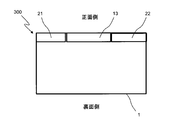
- FIG. 4 is a schematic view of the upper surface of the microwave oven with a ventilation fan.
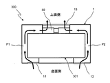
- FIG. 5 is a schematic diagram of a cross section of the microwave oven with a ventilation fan.
- FIG. 6 is a control block diagram of the microwave oven with a ventilation fan.
- FIG. 7 is a control block diagram of the microwave oven with a ventilation fan according to the second embodiment of the present invention.
- FIG. 1A shows a front view of a cooking system including a microwave oven with a ventilation fan according to the first embodiment of the present invention.
- the cooking system includes a cooking table 100 installed on the floor 9, and two kitchen counters installed on both sides of the cooking table 100 and on the floor 9, respectively. 200, 200, a microwave oven 300 with a ventilation fan arranged above the cooking table 100, and cup boards 400, 400 arranged on both sides of the microwave oven 300 with the ventilation fan.
- An IH cooker 101 is attached to the upper side of the cooking table 100.
- the heating cooker 100, the kitchen counters 200, 200, the microwave oven 300 with the ventilation fan, and the cup boards 400, 400 are arranged so that the back faces the wall.
- the microwave oven 300 with a ventilation fan is disposed on the lower side of the housing 1 and includes an infrared sensor 50 that detects the temperature of the object to be heated on the cooking table 100.
- a region A indicated by a dotted line in FIG. 1A is a detection visual field range of the infrared sensor 50.
- FIG. 1B shows a top view of the heating cooker 100, and a region S indicated by a dotted line in FIG. 1B shows a region of the cook top 102 of the IH cooker 101 on the upper side of the heating cooker 100.
- FIG. 2 shows a schematic diagram of the front of the microwave oven 300 with a ventilation fan.
- the microwave oven 300 with a ventilation fan has a heating cabinet (not shown) in a rectangular parallelepiped casing 1 disposed above the cooking counter 100, and a left side is provided at the front opening of the heating cabinet.
- a door 2 that rotates about the center is attached.
- a handle 3 is attached to the door 2 and a heat-resistant door glass 4 is attached to the door 2.
- An operation panel 5 is provided on the right side of the door 2.
- FIG. 3 is a schematic diagram of the bottom surface of the microwave oven 300 with the ventilation fan.
- the left intake port 11 and the right side provided on the lower surface of the housing 1 and in the left-right direction of the housing 1 are spaced apart from each other.
- An air inlet 12 is provided.
- the left intake port 11 and the right intake port 12 are open toward the lower cooking counter 100.
- an infrared sensor 50 is disposed on the lower surface of the housing 1 and on the rear side (wall surface side) on the straight line L passing through the middle of the left air inlet 11 and the right air inlet 12 in the front-rear direction of the housing 1.
- 7 is an illumination unit
- 50 a is a detection surface of the infrared sensor 50.
- FIG. 4 is a schematic view of the upper surface of the microwave oven 300 with the ventilation fan. Air sucked from the left air inlet 11 and the right air inlet 12 is introduced into the upper central portion of the housing 1 and the front side. An exhaust port 13 for discharging is provided. Further, exhaust ports 21 and 22 for discharging cooling air of the microwave oven main body 301 (shown in FIG. 5) are provided on both sides of the exhaust port 13.
- FIG. 5 shows a schematic view of a cross section of the microwave oven 300 with the ventilation fan.
- This microwave oven 300 with a ventilation fan has a microwave oven body 301 disposed in the housing 1 as shown in FIG. Further, ducts P 1 and P 2 that guide from the left intake port 11 and the right intake port 12 to the exhaust port 13 are arranged in the housing 1.
- a ventilation fan 30 that discharges the air sucked from the left air inlet 11 and the right air inlet 12 to the outside through the ducts P1 and P2 from the exhaust port 13 is disposed on the upper side in the housing 1.
- FIG. 6 shows a control block diagram of the microwave oven 300 with a ventilation fan.
- the microwave oven 300 with a ventilation fan includes a control device 90 including a microcomputer and an input / output circuit.
- the control device 90 includes the operation panel 5, a temperature sensor 6 that detects the temperature in the heating chamber, the inverter circuit 10 that drives the magnetron 20, the ventilation fan 30, and the temperature of the object to be heated on the cooking counter 100. Infrared sensor 50 for detecting is connected.
- the controller 90 determines whether the temperature of the object to be heated on the cooking table 100 detected by the infrared sensor 50 and the heating control unit 90a that controls the inverter circuit 10 that drives the magnetron 20 is equal to or higher than the start determination temperature. And a stop determination unit 90c for determining whether the temperature of the object to be heated on the cooking table 100 detected by the infrared sensor 50 is equal to or lower than the stop determination temperature.
- the controller 90 starts the operation of the ventilation fan 30.
- the control device 90 stops the operation of the ventilation fan 30.
- the air flow during operation of the ventilation fan 30 is controlled by the control device 90 based on the temperature of the object to be heated on the cooking table 100 detected by the infrared sensor 50.
- the rotational speed of the ventilation fan 30 may be controlled so that the fan air volume increases continuously as the temperature of the object to be heated on the cooking table 100 increases, or the fan air volume increases in stages.
- the rotational speed of the ventilation fan 30 may be controlled.
- the ventilation fan 30 is controlled by the control device 90 based on the temperature of the object to be heated on the cooking table 100 detected by the infrared sensor 50. It becomes possible to accurately control the ventilation fan 30 by accurately determining the temperature of the object to be heated.
- the infrared sensor 50 allows the heating object to be heated on the cooking table 100 even if the temperature of the object to be heated on the cooking table 100 is suppressed as compared with the case of cooking with high heat from a gas stove. It becomes possible to accurately determine the temperature of the object to be heated, and the ventilation fan 30 can be operated. This eliminates the need for the user to manually control the ventilation fan 30 and greatly improves convenience.
- an infrared sensor 50 is disposed between the lower surface of the casing 1 of the microwave oven with a ventilation fan and between the left air inlet 11 and the right air inlet 12, so that the air is sucked into the left air inlet 11 and the right air inlet 12.
- the heated air or steam on the cooking table 100 can be prevented from interfering with the detection of the infrared sensor 50, and the temperature of the object to be heated on the cooking table 100 can be detected more accurately.
- the start determination part 90b of the said control apparatus 90 determines with the temperature of the to-be-heated material on the heating cooker 100 being more than the preset start determination temperature, the driving
- the stop determination part 90c of the said control apparatus 90 determines with the temperature of the to-be-heated object on the heating cooker 100 being below the preset stop determination temperature, the operation
- the temperature of the object to be heated in the area S (shown in FIG. 1B) of the cooktop 102 on the cooking table 100 is detected by the infrared sensor 50, a hot pot outside the area S of the cooktop 102 is used. Therefore, it is possible to prevent the ventilation fan 30 from malfunctioning.
- the cooking system provided with the microwave oven 300 with a ventilation fan which can control the ventilation fan 30 exactly based on the detection result of the infrared sensor 50 is realizable.
- the left intake port 11 and the right intake port 12 provided at the lower surface of the casing 1 of the microwave oven 300 with a ventilation fan and spaced in the horizontal direction of the casing 1 are provided.
- the intake ports are not limited to this, and three or more intake ports may be provided, or circular, elliptical, or polygonal intake ports may be provided.
- the infrared sensor 50 is disposed on the wall surface side, the infrared sensor may be disposed in front of the straight line L.
- the placement of the infrared sensor is not limited to this. Good.
- ventilation fan 30 control function may be provided in a ventilation fan control device different from the control device 90.
- FIG. 7 shows a control block diagram of a microwave oven with a ventilation fan according to the second embodiment of the present invention.
- the microwave oven with the ventilation fan of the second embodiment has the same configuration as the microwave oven with the ventilation fan of the first embodiment except for the cover opening / closing section 40, the cover 41, and the control device 1090.
- the microwave oven with a ventilation fan includes a cover 41 that covers the detection surface 50a (shown in FIG. 1B) of the infrared sensor 50, and a cover opening / closing unit 40 that opens and closes the cover 41.
- the control device 1090 includes the operation panel 5, the temperature sensor 6 that detects the temperature in the heating chamber, the inverter circuit 10 that drives the magnetron 20, the ventilation fan 30, and the cover opening and closing unit 40 that opens and closes the cover 41.
- An infrared sensor 50 that detects the temperature of an object to be heated on the cooking table 100 is connected.
- the control device 1090 includes a heating control unit 1090a that controls the inverter circuit 10 that drives the magnetron 20, and the temperature of the object to be heated on the cooking table 100 detected by the infrared sensor 50 is equal to or higher than a start determination temperature. And a stop determination unit 1090c that determines whether the temperature of the object to be heated on the cooking table 100 detected by the infrared sensor 50 is equal to or lower than the stop determination temperature.
- the controller 1090 starts the operation of the ventilation fan 30.
- the control device 1090 stops the operation of the ventilation fan 30.
- the cover 41 (cover) covering the detection surface 50a of the infrared sensor 50 is opened and closed by the cover opening / closing unit 40 (cover opening / closing unit) controlled by the control device 1090.
- the cover opening / closing unit 40 cover opening / closing unit
- control device 1090 opens the cover 41 intermittently from a state in which the cover 41 is closed at every preset time during the operation of the ventilation fan 30, and the infrared sensor 50 causes the cover on the cooking counter 100 to be covered.
- the temperature of the heated object is detected.
- the stop determination part 1090c determines that the temperature of the to-be-heated object on the heating cooker 100 is below a stop determination temperature, the control apparatus 1090 will stop the operation
- movement of the ventilation fan 30 and will close the cover 41.
- movement of the ventilation fan 30 and will close the cover 41.
- movement of the ventilation fan 30 will close the cover 41.
- the cover 41 that covers the detection surface 50a of the infrared sensor 50 and the cover opening / closing part 40 that opens and closes the cover 41 are provided.
- the detection surface 50a of the infrared sensor 50 is made of glass that transmits infrared rays. It may be covered.
- the microwave oven with a ventilation fan according to the third embodiment of the present invention has the same configuration as the microwave oven with a ventilation fan according to the first embodiment except for the operations of the infrared sensor 50 and the control device 90.
- an area sensor that detects a plurality of areas is used for the infrared sensor 50.
- the control device 90 detects the temperatures of a plurality of areas on the heating cooker 100 detected by the infrared sensor 50. Whether it is high or not can be detected.
- the air volume of the ventilation fan 30 can be adjusted according to the temperature of each stove detected by the infrared sensor 50, and ventilation can be performed efficiently.
- the number of the stove is informed of high temperature abnormality.
- An alarm may be output by voice or display.
- the microwave oven with a ventilation fan of the present invention and the cooking system including the same are not limited to the cooking systems of the first to third embodiments, and may be cooking systems having other configurations, and have an induction heating cooker. What is necessary is just a cooking system provided with the microwave oven with a ventilation fan arrange
- the microwave oven with a ventilation fan of the present invention is A housing 1 disposed above the cooking table 100; A microwave oven body 301 disposed in the housing 1; Intake ports 11 and 12 provided on the lower side of the housing 1; Ducts P1 and P2 provided in the housing 1 and guided from the intake ports 11 and 12 to the exhaust port 13; A ventilation fan 30 disposed in the housing 1 for discharging the air sucked from the intake ports 11 and 12 to the outside from the exhaust port 13 through the ducts P1 and P2; An infrared sensor 50 which is disposed on the lower side of the casing 1 and detects the temperature of an object to be heated on the cooking table 100; Control devices 90 and 1090 for controlling the ventilation fan 30 based on the temperature of the object to be heated on the cooking table 100 detected by the infrared sensor 50 are provided.
- the ventilating fan 30 is controlled by the control devices 90 and 1090 based on the temperature of the object to be heated on the heating cooker 100 detected by the infrared sensor 50. It becomes possible to accurately control the ventilation fan 30 by accurately determining the temperature of the object. For example, when cooking with an IH cooker, even if the temperature of the object to be heated on the cooking table 100 is prevented from rising compared to when cooking with a strong gas stove, the infrared sensor 50 causes the heating table 100 to be heated. Therefore, the temperature of the object to be heated can be accurately determined, and the ventilation fan 30 can be operated. This eliminates the need for the user to manually control the ventilation fan 30 and greatly improves convenience.
- the intake ports 11 and 12 are a left intake port 11 and a right intake port 12 that are provided on the lower surface of the housing 1 and spaced apart from each other in the left-right direction of the housing 1.
- the infrared sensor 50 is disposed on the lower surface of the housing 1 and between the left air inlet 11 and the right air inlet 12.
- the infrared sensor 50 is disposed between the lower surface of the housing 1 and between the left intake port 11 and the right intake port 12, so that the heat sucked into the left intake port 11 and the right intake port 12 is heated. Hot air and steam on the cooking table 100 can be prevented from interfering with detection of the infrared sensor 50, and the temperature of the object to be heated on the heating cooking table 100 can be detected more accurately.
- the control devices 90 and 1090 are Start determination units 90b and 1090b for determining whether or not the temperature of the object to be heated on the cooking table 100 detected by the infrared sensor 50 is equal to or higher than a preset start determination temperature; When the start determination units 90b and 1090b determine that the temperature of the object to be heated on the cooking table 100 is equal to or higher than the start determination temperature, the operation of the ventilation fan 30 is started.
- the control devices 90 and 1090 control the ventilation fan 30. Since the operation is started, the ventilation fan 30 can be automatically operated.
- a cover opening / closing section 40 that is controlled by the control device 1090 and opens and closes the cover 41 is provided.
- the cover 41 that covers at least the detection surface of the infrared sensor 50 is opened and closed by the cover opening / closing unit 40 controlled by the control device 1090. Therefore, when the detection of the infrared sensor 50 is unnecessary during cooking. By closing the cover 41, it is possible to prevent the detection surface of the infrared sensor 50 from becoming dirty.
- a cover 41 covering at least the detection surface of the infrared sensor 50;
- a cover opening / closing unit 40 controlled by the control device 1090 to open and close the cover 41;
- the control device 1090 is A stop determination unit 1090c that determines whether or not the temperature of the object to be heated on the cooking table 100 detected by the infrared sensor 50 is equal to or lower than a preset stop determination temperature;
- the cover 41 is intermittently opened from a state in which the cover 41 is closed every preset time, and the infrared sensor 50 causes the object to be heated on the cooking table 100 to be heated. Detect the temperature, When the stop determination unit 1090c determines that the temperature of the object to be heated on the cooking table 100 is equal to or lower than the stop determination temperature, the operation of the ventilation fan 30 is stopped.
- the control device 1090 opens the cover 41 intermittently from a state in which the cover 41 is closed at every preset time during the operation of the ventilation fan 30, and the heating cooker by the infrared sensor 50.
- the temperature of the object to be heated on 100 is detected.
- the stop determination part 1090c determines that the temperature of the to-be-heated object on the heating cooker 100 is below a stop determination temperature, the control apparatus 90 and 1090 will stop the operation
- movement of the ventilation fan 30 FIG.
- the infrared sensor 50 detects the temperature of the object to be heated in the region S of the cooktop 102 on the cooking table 100.
- the infrared sensor 50 since the temperature of the object to be heated in the area S of the cook top 102 on the cooking table 100 is detected by the infrared sensor 50, ventilation is performed with a hot pot or the like outside the area S of the cook top 102. It is possible to prevent the fan 30 from malfunctioning.
- a cooking system including the microwave oven 300 with the ventilation fan that can accurately control the ventilation fan 30 based on the detection result of the infrared sensor 50 can be realized.
Landscapes
- Engineering & Computer Science (AREA)
- Chemical & Material Sciences (AREA)
- Combustion & Propulsion (AREA)
- Mechanical Engineering (AREA)
- General Engineering & Computer Science (AREA)
- Physics & Mathematics (AREA)
- Electromagnetism (AREA)
- Electric Ovens (AREA)
- Induction Heating Cooking Devices (AREA)
- Ventilation (AREA)
Abstract
La présente invention concerne un four à micro-ondes doté d'un ventilateur soufflant solidaire, le four à micro-ondes comprenant : une enveloppe (1) disposée sur une surface de cuisson chauffante (100) ; un corps principal de four à micro-ondes disposé dans l'enveloppe (1) ; des orifices d'aspiration disposés sur un côté inférieur de l'enveloppe (1) ; un conduit disposé dans l'enveloppe (1) et assurant un guidage à partir d'orifices d'aspiration (11, 12) vers un orifice d'évacuation ; un ventilateur soufflant disposé dans l'enveloppe (1) et destiné à évacuer, à travers le conduit, l'air aspiré par les orifices d'aspiration (11, 12), de l'orifice d'évacuation vers l'extérieur ; un capteur infrarouge (50) disposé sur le côté inférieur de l'enveloppe (1) et permettant de détecter la température d'un objet en cours de chauffage sur la surface de cuisson chauffante (100) ; et un dispositif de commande destiné à commander le ventilateur soufflant sur la base de la température, détectée par le capteur infrarouge (50), de l'objet en cours de chauffage sur la surface de cuisson chauffante (100).
Priority Applications (2)
| Application Number | Priority Date | Filing Date | Title |
|---|---|---|---|
| EP17860679.4A EP3527899A4 (fr) | 2016-10-12 | 2017-02-06 | Four à micro-ondes doté de ventilateur soufflant solidaire et système de cuisson |
| US16/326,644 US20210100078A1 (en) | 2016-10-12 | 2017-02-06 | Ventilation-fan-equipped microwave oven, and cooking system |
Applications Claiming Priority (2)
| Application Number | Priority Date | Filing Date | Title |
|---|---|---|---|
| JP2016201182A JP2019215091A (ja) | 2016-10-12 | 2016-10-12 | 換気ファン付き電子レンジおよび調理システム |
| JP2016-201182 | 2016-10-12 |
Publications (1)
| Publication Number | Publication Date |
|---|---|
| WO2018070060A1 true WO2018070060A1 (fr) | 2018-04-19 |
Family
ID=61905322
Family Applications (1)
| Application Number | Title | Priority Date | Filing Date |
|---|---|---|---|
| PCT/JP2017/004236 Ceased WO2018070060A1 (fr) | 2016-10-12 | 2017-02-06 | Four à micro-ondes doté de ventilateur soufflant solidaire et système de cuisson |
Country Status (4)
| Country | Link |
|---|---|
| US (1) | US20210100078A1 (fr) |
| EP (1) | EP3527899A4 (fr) |
| JP (1) | JP2019215091A (fr) |
| WO (1) | WO2018070060A1 (fr) |
Families Citing this family (2)
| Publication number | Priority date | Publication date | Assignee | Title |
|---|---|---|---|---|
| KR102663290B1 (ko) * | 2019-02-20 | 2024-05-03 | 엘지전자 주식회사 | 배기장치 |
| CN114811684B (zh) * | 2022-04-08 | 2023-06-20 | 宁波方太厨具有限公司 | 一种烹饪装置的控制方法 |
Citations (5)
| Publication number | Priority date | Publication date | Assignee | Title |
|---|---|---|---|---|
| JPH0293231A (ja) * | 1988-09-29 | 1990-04-04 | Fuji Kogyo Kk | 温度調節機能を有するレンジフード |
| JP2001112291A (ja) * | 1999-10-05 | 2001-04-20 | Samsung Electronics Co Ltd | フードモータ駆動制御回路 |
| JP2008082634A (ja) * | 2006-09-28 | 2008-04-10 | Matsushita Electric Ind Co Ltd | レンジフード |
| JP2009092338A (ja) * | 2007-10-11 | 2009-04-30 | Panasonic Corp | レンジフードファン |
| JP2009121751A (ja) * | 2007-11-15 | 2009-06-04 | Panasonic Corp | レンジフード |
Family Cites Families (3)
| Publication number | Priority date | Publication date | Assignee | Title |
|---|---|---|---|---|
| KR20050026607A (ko) * | 2003-09-09 | 2005-03-15 | 삼성전자주식회사 | 후드 겸용 전자레인지 및 그 제어 방법 |
| JP5899393B2 (ja) * | 2011-02-25 | 2016-04-06 | パナソニックIpマネジメント株式会社 | レンジフード |
| US20160131366A1 (en) * | 2014-11-10 | 2016-05-12 | Foremost Groups, Inc. | Oven range ventilator with microwave compartment |
-
2016
- 2016-10-12 JP JP2016201182A patent/JP2019215091A/ja active Pending
-
2017
- 2017-02-06 US US16/326,644 patent/US20210100078A1/en not_active Abandoned
- 2017-02-06 WO PCT/JP2017/004236 patent/WO2018070060A1/fr not_active Ceased
- 2017-02-06 EP EP17860679.4A patent/EP3527899A4/fr not_active Withdrawn
Patent Citations (5)
| Publication number | Priority date | Publication date | Assignee | Title |
|---|---|---|---|---|
| JPH0293231A (ja) * | 1988-09-29 | 1990-04-04 | Fuji Kogyo Kk | 温度調節機能を有するレンジフード |
| JP2001112291A (ja) * | 1999-10-05 | 2001-04-20 | Samsung Electronics Co Ltd | フードモータ駆動制御回路 |
| JP2008082634A (ja) * | 2006-09-28 | 2008-04-10 | Matsushita Electric Ind Co Ltd | レンジフード |
| JP2009092338A (ja) * | 2007-10-11 | 2009-04-30 | Panasonic Corp | レンジフードファン |
| JP2009121751A (ja) * | 2007-11-15 | 2009-06-04 | Panasonic Corp | レンジフード |
Non-Patent Citations (1)
| Title |
|---|
| See also references of EP3527899A4 * |
Also Published As
| Publication number | Publication date |
|---|---|
| JP2019215091A (ja) | 2019-12-19 |
| US20210100078A1 (en) | 2021-04-01 |
| EP3527899A4 (fr) | 2020-06-17 |
| EP3527899A1 (fr) | 2019-08-21 |
Similar Documents
| Publication | Publication Date | Title |
|---|---|---|
| KR101520499B1 (ko) | 오븐 레인지 | |
| US20080156313A1 (en) | Electric oven with hood | |
| EP3438552B1 (fr) | Four | |
| KR102035800B1 (ko) | 후드 겸용 전자레인지 및 이를 포함하는 환기 시스템 | |
| KR100386009B1 (ko) | 가열조리장치 | |
| JP6446672B2 (ja) | 加熱調理器 | |
| WO2018070060A1 (fr) | Four à micro-ondes doté de ventilateur soufflant solidaire et système de cuisson | |
| US11778702B2 (en) | Over-the-range microwave including cooling fans and method of operating an over-the-range microwave | |
| JP6446673B2 (ja) | 加熱調理器 | |
| KR101625679B1 (ko) | 후드 겸용 전자레인지 | |
| KR20200021755A (ko) | 콤비형 전기 조리기기 및 그 제어 방법 | |
| US11739947B2 (en) | Oven appliance with convection bake and broil | |
| US11796178B2 (en) | Oven appliance with rear gas burner | |
| KR20110015784A (ko) | 조리기기 | |
| US20220146111A1 (en) | Cooling system for a control panel of an oven appliance | |
| KR101650574B1 (ko) | 조리기기 | |
| JP2017083100A (ja) | 加熱調理器 | |
| JP3913641B2 (ja) | 誘導加熱調理器 | |
| US20250305683A1 (en) | Oven appliance with airflow deflection | |
| KR100826708B1 (ko) | 오븐의 공기 배출 시스템 | |
| KR100700771B1 (ko) | 슬라이딩 타입의 백가드가 구비된 오븐레인지 | |
| JP2019148343A (ja) | 加熱調理器 | |
| US20250305679A1 (en) | Oven appliance with a single heating element | |
| KR100820835B1 (ko) | 조리기기 | |
| KR20070013087A (ko) | 조리 시스템 및 그의 제어 방법 |
Legal Events
| Date | Code | Title | Description |
|---|---|---|---|
| 121 | Ep: the epo has been informed by wipo that ep was designated in this application |
Ref document number: 17860679 Country of ref document: EP Kind code of ref document: A1 |
|
| NENP | Non-entry into the national phase |
Ref country code: DE |
|
| ENP | Entry into the national phase |
Ref document number: 2017860679 Country of ref document: EP Effective date: 20190513 |
|
| NENP | Non-entry into the national phase |
Ref country code: JP |