WO2018070272A1 - Système d'imagerie par rayonnement et son procédé de commande, dispositif de commande et son procédé de commande, et programme informatique - Google Patents
Système d'imagerie par rayonnement et son procédé de commande, dispositif de commande et son procédé de commande, et programme informatique Download PDFInfo
- Publication number
- WO2018070272A1 WO2018070272A1 PCT/JP2017/035485 JP2017035485W WO2018070272A1 WO 2018070272 A1 WO2018070272 A1 WO 2018070272A1 JP 2017035485 W JP2017035485 W JP 2017035485W WO 2018070272 A1 WO2018070272 A1 WO 2018070272A1
- Authority
- WO
- WIPO (PCT)
- Prior art keywords
- imaging
- radiation
- information
- acquires
- devices
- Prior art date
- Legal status (The legal status is an assumption and is not a legal conclusion. Google has not performed a legal analysis and makes no representation as to the accuracy of the status listed.)
- Ceased
Links
Images






Classifications
-
- A—HUMAN NECESSITIES
- A61—MEDICAL OR VETERINARY SCIENCE; HYGIENE
- A61B—DIAGNOSIS; SURGERY; IDENTIFICATION
- A61B6/00—Apparatus or devices for radiation diagnosis; Apparatus or devices for radiation diagnosis combined with radiation therapy equipment
- A61B6/56—Details of data transmission or power supply, e.g. use of slip rings
- A61B6/563—Details of data transmission or power supply, e.g. use of slip rings involving image data transmission via a network
-
- A—HUMAN NECESSITIES
- A61—MEDICAL OR VETERINARY SCIENCE; HYGIENE
- A61B—DIAGNOSIS; SURGERY; IDENTIFICATION
- A61B6/00—Apparatus or devices for radiation diagnosis; Apparatus or devices for radiation diagnosis combined with radiation therapy equipment
- A61B6/54—Control of apparatus or devices for radiation diagnosis
-
- A—HUMAN NECESSITIES
- A61—MEDICAL OR VETERINARY SCIENCE; HYGIENE
- A61B—DIAGNOSIS; SURGERY; IDENTIFICATION
- A61B6/00—Apparatus or devices for radiation diagnosis; Apparatus or devices for radiation diagnosis combined with radiation therapy equipment
-
- A—HUMAN NECESSITIES
- A61—MEDICAL OR VETERINARY SCIENCE; HYGIENE
- A61B—DIAGNOSIS; SURGERY; IDENTIFICATION
- A61B6/00—Apparatus or devices for radiation diagnosis; Apparatus or devices for radiation diagnosis combined with radiation therapy equipment
- A61B6/44—Constructional features of apparatus for radiation diagnosis
-
- A—HUMAN NECESSITIES
- A61—MEDICAL OR VETERINARY SCIENCE; HYGIENE
- A61B—DIAGNOSIS; SURGERY; IDENTIFICATION
- A61B6/00—Apparatus or devices for radiation diagnosis; Apparatus or devices for radiation diagnosis combined with radiation therapy equipment
- A61B6/56—Details of data transmission or power supply, e.g. use of slip rings
- A61B6/566—Details of data transmission or power supply, e.g. use of slip rings involving communication between diagnostic systems
-
- G—PHYSICS
- G16—INFORMATION AND COMMUNICATION TECHNOLOGY [ICT] SPECIALLY ADAPTED FOR SPECIFIC APPLICATION FIELDS
- G16H—HEALTHCARE INFORMATICS, i.e. INFORMATION AND COMMUNICATION TECHNOLOGY [ICT] SPECIALLY ADAPTED FOR THE HANDLING OR PROCESSING OF MEDICAL OR HEALTHCARE DATA
- G16H30/00—ICT specially adapted for the handling or processing of medical images
- G16H30/20—ICT specially adapted for the handling or processing of medical images for handling medical images, e.g. DICOM, HL7 or PACS
-
- G—PHYSICS
- G16—INFORMATION AND COMMUNICATION TECHNOLOGY [ICT] SPECIALLY ADAPTED FOR SPECIFIC APPLICATION FIELDS
- G16H—HEALTHCARE INFORMATICS, i.e. INFORMATION AND COMMUNICATION TECHNOLOGY [ICT] SPECIALLY ADAPTED FOR THE HANDLING OR PROCESSING OF MEDICAL OR HEALTHCARE DATA
- G16H40/00—ICT specially adapted for the management or administration of healthcare resources or facilities; ICT specially adapted for the management or operation of medical equipment or devices
- G16H40/60—ICT specially adapted for the management or administration of healthcare resources or facilities; ICT specially adapted for the management or operation of medical equipment or devices for the operation of medical equipment or devices
- G16H40/63—ICT specially adapted for the management or administration of healthcare resources or facilities; ICT specially adapted for the management or operation of medical equipment or devices for the operation of medical equipment or devices for local operation
-
- G—PHYSICS
- G16—INFORMATION AND COMMUNICATION TECHNOLOGY [ICT] SPECIALLY ADAPTED FOR SPECIFIC APPLICATION FIELDS
- G16H—HEALTHCARE INFORMATICS, i.e. INFORMATION AND COMMUNICATION TECHNOLOGY [ICT] SPECIALLY ADAPTED FOR THE HANDLING OR PROCESSING OF MEDICAL OR HEALTHCARE DATA
- G16H40/00—ICT specially adapted for the management or administration of healthcare resources or facilities; ICT specially adapted for the management or operation of medical equipment or devices
- G16H40/60—ICT specially adapted for the management or administration of healthcare resources or facilities; ICT specially adapted for the management or operation of medical equipment or devices for the operation of medical equipment or devices
- G16H40/67—ICT specially adapted for the management or administration of healthcare resources or facilities; ICT specially adapted for the management or operation of medical equipment or devices for the operation of medical equipment or devices for remote operation
-
- A—HUMAN NECESSITIES
- A61—MEDICAL OR VETERINARY SCIENCE; HYGIENE
- A61B—DIAGNOSIS; SURGERY; IDENTIFICATION
- A61B6/00—Apparatus or devices for radiation diagnosis; Apparatus or devices for radiation diagnosis combined with radiation therapy equipment
- A61B6/46—Arrangements for interfacing with the operator or the patient
- A61B6/461—Displaying means of special interest
- A61B6/462—Displaying means of special interest characterised by constructional features of the display
-
- A—HUMAN NECESSITIES
- A61—MEDICAL OR VETERINARY SCIENCE; HYGIENE
- A61B—DIAGNOSIS; SURGERY; IDENTIFICATION
- A61B6/00—Apparatus or devices for radiation diagnosis; Apparatus or devices for radiation diagnosis combined with radiation therapy equipment
- A61B6/46—Arrangements for interfacing with the operator or the patient
- A61B6/467—Arrangements for interfacing with the operator or the patient characterised by special input means
- A61B6/469—Arrangements for interfacing with the operator or the patient characterised by special input means for selecting a region of interest [ROI]
-
- A—HUMAN NECESSITIES
- A61—MEDICAL OR VETERINARY SCIENCE; HYGIENE
- A61B—DIAGNOSIS; SURGERY; IDENTIFICATION
- A61B6/00—Apparatus or devices for radiation diagnosis; Apparatus or devices for radiation diagnosis combined with radiation therapy equipment
- A61B6/54—Control of apparatus or devices for radiation diagnosis
- A61B6/548—Remote control of the apparatus or devices
Definitions
- the present invention relates to a radiation imaging system, a control method thereof, a control device, a control method thereof, and a computer program.
- Patent Document 1 a plurality of radiation detectors can be imaged in advance, and radiation imaging can be performed regardless of which radiation detector is irradiated with radiation. Therefore, the radiation flows in the same flow as when a conventional film is used.
- a radiation imaging system capable of imaging is described. In the configuration of Patent Document 1, the radiation images of all the radiation detectors are in a state that can be captured.
- An object of the present invention is to provide a technique capable of efficiently performing radiation imaging even when all radiation detectors are not in an imageable state.
- a radiation imaging system comprises the following arrangement. That is, A plurality of imaging devices that generate images based on radiation emitted from a radiation generator that emits radiation; and A radiation imaging system comprising: a control device that communicates with the plurality of imaging devices; The control device includes: Obtaining means for obtaining imaging information from each of the plurality of imaging devices; Selection means for selecting one imaging device from the plurality of imaging devices based on the imaging information acquired by the acquisition unit; Image acquisition means for acquiring an image from the imaging device selected by the selection means, The said control apparatus is provided with the setting means which sets the imaging device from which the said acquisition means acquires the said imaging information, It is characterized by the above-mentioned.
- the accompanying drawings are included in the specification, constitute a part thereof, show an embodiment of the present invention, and are used to explain the principle of the present invention together with the description.
- the functional block diagram which shows the software structure of a control apparatus.
- the flowchart which shows the operation
- the flowchart which shows the operation
- the figure which shows an example of the setting screen of the radiation detector used for imaging.
- the flowchart which shows the process sequence which sets the radiation detector of imaging object.
- the flowchart which shows the process sequence which sets an imaging target from imaging inspection information.
- the flowchart which shows an example of the process sequence which sets the imaging target of a radiation detector.
- FIG. 1 is a schematic diagram showing an example of a schematic configuration of a radiation imaging system 100 according to an embodiment (first embodiment) of the present invention.
- the radiation imaging system 100 includes a control device 110, radiation generators 114A, 114B, and 114C, radiation detectors 115A, 115B, and 115C, an RIS 130, a PACS 140, and a HIS 150.
- RIS is an abbreviation for Radiology Information Systems.
- PACS is an abbreviation for Picture Archiving and Communication Systems (image server).
- HIS is an abbreviation for Hospital Information Systems.
- the radiation generators 114A, 114B, and 114C are collectively referred to as the radiation generator 114
- the radiation detectors 115A, 115B, and 115C are collectively referred to as the radiation detector 115.
- the control device (imaging control device) 110 is connected to the display unit 112, the operation unit 113, the radiation generation units 114A, 114B, and 114C, and the plurality of radiation detectors 115A and 115B in a wired manner, and communicates with each device. Control its operation. Wired communication can be performed via a LAN (Local Area Network) such as Ethernet (registered trademark), but communication may be performed by other communication methods.
- the radiation detector 115C is wirelessly connected to the control device 110, and the control device 110 controls the operation of the radiation detector 115C via wireless communication. Wireless communication between the radiation detector 115C and the control device 110 is performed by a wireless LAN, but other wireless communication methods such as Bluetooth (registered trademark) may be used.
- the control device 110 is connected to the RIS 130, the PACS 140, and the HIS 150 via the network 120, and can exchange radiographic images, patient information, and the like.
- the display unit 112 displays imaging examination information, captured radiographic images, various types of information, and the like.
- the operation unit 113 receives input information from the operator.
- the display unit 112 is a monitor (for example, a liquid crystal display), and the operation unit 113 is a keyboard, a pointing device (for example, a mouse), or a touch panel.
- Radiation generators (radiation generators) 114A, 114B, and 114C include radiation tubes that generate radiation, and irradiate the patients 1000A, 1000B, and 1000C that are subjects.
- the patient 1000A is in the standing position
- 1000B is in the supine position
- 1000C is in the other position
- the radiation generators 114A, 114B, 114C and the radiation detectors 115A, 115B, 115C are arranged at positions suitable for imaging.
- the radiation generation units 114A, 114B, and 114C are respectively installed in a room where radiation imaging is performed, and the location range in which each radiation generation unit 114 emits radiation is constant. An example limited to a range will be described. However, you may use a portable thing as a radiation generation part.
- the plurality of radiation detectors (radiation imaging devices) 115A, 115B, and 115C generate images based on the radiation emitted from the radiation generation units 114A, 114B, and 114C, respectively.
- the control device 110 performs image processing on the radiation image data detected and acquired by the radiation detectors 115 ⁇ / b> A, 115 ⁇ / b> B, and 115 ⁇ / b> C, and displays the radiation image on the display unit 112.
- the radiation detectors 115 ⁇ / b> A and 115 ⁇ / b> B are installed in a room or a desk according to the location range in which the radiation generators 114 ⁇ / b> A and 114 ⁇ / b> B emit radiation.
- the radiation detector 115 ⁇ / b> C is a portable radiation detection device, and is connected to the control device 110 wirelessly as described above.
- the control device 110 wirelessly as described above.
- a plurality of devices of the same type exist as the radiation detector 115C, and any of these devices is used to detect radiation emitted from the radiation generation unit 114C.
- the radiation imaging system 100 which concerns on this embodiment demonstrates as what contains RIS130, PACS140, and HIS150, you may make it the structure which does not contain at least one part of these.
- FIG. 1 shows an example in which the radiation generation units 114A, 114B, and 114C and the radiation detectors 115A, 115B, and 115C exist as the radiation generation unit and the radiation detector.
- the combination is not limited to this.
- a further radiation generator and radiation detector combination may be included in the radiation imaging system 100.
- FIG. 2A is a schematic diagram illustrating an example of a hardware configuration of the control device 110.
- the control device 110 includes a CPU 201, a RAM 202, a ROM 203, an external memory 204, and a communication I / F unit 205, and they are connected to each other via a bus.
- a CPU (central processing unit) 201 controls the operation of the control device 110 in an integrated manner, and controls each component (RAM 202 to communication I / F unit 205) shown in FIG. 2A via a bus. .
- a RAM (writable memory) 202 functions as a main memory, work area, and the like of the CPU 201.
- the CPU 201 loads necessary computer programs 2031 and basic data from the ROM 203 into the RAM 202 and executes the computer programs 2031 and the like, thereby realizing various functional operations.
- a ROM (read only memory) 203 stores computer programs 2031 and basic data necessary for the CPU 201 to execute processing. Note that the computer program 2031 may be stored in the external memory 204.
- the external memory 204 is a mass storage device, and is realized by, for example, a hard disk device or an IC memory.
- the external memory 204 stores, for example, various data and various information necessary for the CPU 201 to perform processing using the computer program 2031 and the like. Also, the external memory 204 stores, for example, various data and various information obtained by the CPU 201 performing processing using the computer program 2031 or the like.
- the communication I / F (interface) unit 205 manages communication with the outside.
- the bus is used to connect the CPU 201, the RAM 202, the ROM 203, the external memory 204, and the communication I / F unit 205 so that they can communicate with each other.
- the control device 110 is provided as a dedicated embedded device, but may be realized by a general-purpose information processing device such as a PC (personal computer) or a tablet terminal.
- a general-purpose information processing device such as a PC (personal computer) or a tablet terminal.
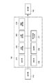
- FIG. 2B is a functional block diagram showing a software configuration of the control device 110 according to the present embodiment.
- the control device 110 includes a control unit 211, a comparison / selection unit 212, an image acquisition unit 213, an information acquisition unit 214, a setting unit 215, a management unit 216, and a setting target input unit 217.
- Each function is realized by the CPU 201 expanding and executing the computer program 2031 stored in the ROM 203 on the RAM 202.
- the control unit 211 determines, creates, and edits the presence / absence of various setting information set in the radiation imaging system 100.
- the comparison / selection unit 212 selects the radiation detectors 115A and 115B based on the information acquired by the information acquisition unit 214.
- the image acquisition unit 213 acquires a radiation image from the radiation detector selected by the comparison / selection unit 212.
- the information acquisition unit (radiation detector information acquisition unit) 214 acquires radiation detector information from the radiation detectors 115A and 115B that have performed radiation imaging, or acquires information when radiation is emitted from the radiation generation units 114A and 114B. I do.
- the setting unit (imaging target setting unit) 215 sets whether each radiation detector registered in the radiation imaging system 100 is a radiation detector used for imaging.
- the management unit (installation status management unit) 216 manages the installation status such as whether the radiation detector is installed in a standing frame, a standing table, or the like.
- the setting target input unit 217 receives a user operation as to whether the radiation detector is used for imaging.
- each functional block described above is merely an example, and the control device 110 may not include a part of each functional block described above, or may include a further functional block.
- FIG. 3 is a flowchart showing an example of operations from preparation for radiation imaging to radiation imaging by the imaging control device (control device) 110 and the first and second radiation imaging devices (radiation detectors) 115. .
- the operation of the imaging control apparatus 110 shown below is realized by the CPU 201 executing a predetermined computer program.
- the operations of the first radiation imaging apparatus (for example, 115A) and the second radiation imaging apparatus (for example, 115B) are performed by a predetermined computer program stored in a memory (not illustrated) by a CPU (not illustrated) of the radiation imaging apparatus. It is realized by executing.
- a radiation detector for example, 115C
- the first radiation imaging apparatus 115A and the second radiation imaging apparatus 115B are in a standby state. In the standby state, the radiation imaging apparatus 115 establishes communication with the imaging control apparatus 110. In S102, the imaging control apparatus 110 transmits a transition instruction for transitioning to an imaging enabled state to all usable radiation imaging apparatuses 115. In the present embodiment, the first radiation imaging apparatus 115A and the second radiation imaging apparatus 115B correspond to usable radiation imaging apparatuses.
- the first radiation imaging apparatus 115A and the second radiation imaging apparatus 115B make a transition to the imageable state in response to a transition instruction from the imaging control apparatus 110, and indicate that the transition to the imageable state is made. 110 is notified.
- the first radiation imaging apparatus 115 ⁇ / b> A and the second radiation imaging apparatus 115 ⁇ / b> B perform radiation imaging in synchronization with the radiation generation apparatus (radiation generation unit) 114.
- the first radiation imaging apparatus 115A and the second radiation imaging apparatus 115B notify the imaging control apparatus 110 that radiation imaging has been performed.
- FIG. 4 is a flowchart showing an example of an operation after the radiation imaging by the first radiation imaging apparatus 115A and the second radiation imaging apparatus 115B until the imaging control apparatus 110 acquires a radiation image.
- the first radiation imaging apparatus 115A and the second radiation imaging apparatus 115B calculate statistical information of pixel values from the generated radiation image.
- the radiation imaging apparatus 115 transmits the calculated statistical information to the imaging control apparatus 110 as imaging information.
- an average value of pixel values (hereinafter, pixel average value) is used as an example of statistical information.
- the statistical information is not limited to this, and for example, a maximum value, a median value, a variance value, or the like may be used. Alternatively, it may be statistical information such as a maximum value of a difference between adjacent pixel values or a width between a maximum value and a minimum value of pixel values. Further, there may be two or more pieces of statistical information to be calculated.
- the pixel value may be a luminance value or a density value.
- the imaging information may be an image having a smaller data size (for example, a thinned image, a reduced image, etc.) than the captured image generated based on the captured image.
- the imaging control apparatus 110 acquires the pixel average value calculated in S201 from the first radiation imaging apparatus 115A and the second radiation imaging apparatus 115B.
- the imaging control apparatus 110 compares the pixel average values acquired in S202, and selects the radiation imaging apparatus that provided the largest pixel average value.
- the structure which selects the radiation imaging device which provided the largest pixel average value was shown above, it is not limited to this.
- a radiation imaging apparatus that provides statistical information closest to a preset threshold value may be selected.
- the radiation imaging apparatus may be selected by comparing a plurality of statistical information. Further, when the comparison results are the same and one radiation imaging apparatus cannot be selected, the radiation imaging apparatus that has previously notified that the radiation imaging has been performed may be selected.
- the imaging control device 110 acquires a radiation image from the radiation imaging device selected in S203 (here, the first radiation imaging device 115A). That is, the imaging control device 110 requests an image from the first radiation imaging device 115A, and the first radiation imaging device 115A receives a radiation image in response to a request for an image from the imaging control device 110. 110.
- the imaging control device 110 captures a radiation image based on imaging information (for example, a pixel average value) having a data size smaller than that of the radiation image.
- imaging information for example, a pixel average value
- a radiation imaging apparatus to be acquired is selected. Since the imaging control device 110 acquires the radiation image from the selected radiation imaging device, the radiation imaging cycle can be shortened as compared with the configuration in which the radiation images are acquired from all the radiation imaging devices. Therefore, it is possible to realize a radiation imaging system that can perform radiation imaging in a fast cycle while reducing the possibility of giving unnecessary exposure due to re-imaging.
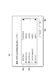
- FIG. 5 is a diagram illustrating an example of the imaging target setting screen 301 displayed on the display unit 112 according to the present embodiment.
- the imaging target setting screen 301 includes a radiation detector display area 302, an imaging target valid check box 303, a setting completion button 304, and a setting cancel button 305.
- the imaging target validity check box 303 is a checkbox for validating the radiation detector designated by the operator as an imaging target.
- a setting cancel button 304 is a button for the operator to instruct to cancel the setting of the imaging target.
- a setting completion button 305 is a button for the operator to instruct confirmation of the setting content of the imaging target.
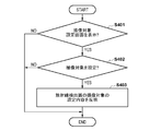
- FIG. 6 is a flowchart illustrating a processing procedure for setting a radiation detector to be imaged in the radiation imaging system 100 according to the present embodiment. Each step in FIG. 6 is executed by the CPU 201 of the control device 110 controlling the radiation imaging system 100 based on the computer program 2031.
- the control unit 211 determines whether the imaging target setting screen 301 of FIG. When displayed (S401; YES), the process proceeds to S402. On the other hand, if it is not displayed (S401; NO), the process ends.
- the setting target input unit 217 determines whether the imaging target setting of the radiation detector has been input by the operator. If entered (S402; YES), the process proceeds to S403. On the other hand, if not input (S402; NO), the process is terminated.
- the setting unit 215 reflects the setting contents of the imaging target of the radiation detector set in S402. That is, imaging information such as statistical information of a captured image is acquired from the radiation detector set as an imaging target by the operator in S402, and imaging information is not acquired from the other radiation detectors.
- radiation is generated from any of the radiation generation units 114A, 114B, and 114C in accordance with the operation of the operator with respect to the operation unit 113.
- imaging information such as statistical information of the captured image is acquired from the radiation detector set in S403, one radiation detector is selected from a plurality of radiation detectors based on the imaging information, and the radiation detector is selected. Perform image acquisition to acquire an image.
- the control device 110 acquires imaging information from each of the plurality of radiation detectors 115, and selects one radiation detector from the plurality of radiation detectors based on the acquired imaging information. Then, an image is acquired from the selected radiation detector.
- the control apparatus 110 sets the radiation detector which acquires imaging information, and acquires imaging information only from the set radiation detector. Specifically, display control is performed to display on the display unit 112 a screen from which a plurality of radiation detectors to be used for imaging can be selected, and imaging information is acquired for the radiation detector selected by the operator on this screen. Set as a radiation detector.
- the operator can arbitrarily set the imaging target radiation detector on the imaging target setting screen 301.
- the radiation detectors for acquiring imaging information for selecting the radiation detectors for acquiring the captured images are narrowed down. Therefore, a captured image can be acquired from the radiation imaging apparatus that has actually performed imaging. Therefore, it is possible to reduce the risk of reduction in imaging efficiency and unnecessary exposure of the human body due to the fact that the radiation detector necessary for detecting the irradiated radiation is not in a detectable state.
- the radiation imaging system of the present embodiment includes a plurality of radiation detectors (imaging devices) that generate images based on radiation emitted from a radiation generation unit (radiation generation device), and a control that communicates with the plurality of radiation generation units.
- imaging devices at least two radiation detectors are selected from the plurality of radiation detectors, and imaging information in an image generated by the selected at least two radiation detectors is acquired.
- at least two radiation detectors are selected by excluding at least one radiation detector from the plurality of radiation detectors. Then, based on the acquired imaging information, one radiation detector is selected from at least two radiation detectors, and image acquisition for acquiring an image from the selected radiation detector is performed.
- a radiation detector that acquires imaging information after selecting a radiation detector that acquires imaging information and acquires an image is selected. select. Therefore, even when some of the radiation detectors are disconnected from the communication, it is possible to acquire a captured image from the radiation detector that has performed imaging.
- a radiation detector for detecting the radiation irradiated from the radiation generating unit is limited. For example, in the example of FIG. 1, when the radiation is emitted from the radiation generator 114A, only the radiation detector 115A detects the radiation, and there is no other way. Similarly, when the radiation is emitted from the radiation generator 114B, only the radiation detector 115B detects the radiation.
- the radiation detector 115C is portable and communicates with the control device 110 wirelessly, and there are a plurality of devices of the same type in such a portable radiation detector. Therefore, when radiation is emitted from the radiation generation unit 114C, it is not immediately clear which radiation detector detects the radiation simply by specifying the radiation generation unit. However, the radiation detectors 115A and 115B are not used when radiation is emitted from the radiation generator 114C.
- a radiation detector that acquires imaging information is set based on the installation state of the radiation generation unit or the radiation detector. That is, according to the specification of the radiation generation unit 114 to be used, imaging information is acquired only from the corresponding radiation detector, and imaging information is not acquired from other radiation detectors. Specifically, when the radiation detector to be used is self-evident, such as in an examination in which imaging is performed in a standing position or a supine position, imaging information is acquired by excluding the radiation detector other than the radiation detector from the imaging target. Automatically excluded from radiation detectors. That is, at least one radiation detector that does not correspond to the radiation generator to be used is excluded from the radiation detector that acquires the imaging information. Therefore, according to the present embodiment, the time until transition to the imaging enabled state is reduced. In addition, the operator can save the trouble of manually setting the radiation detectors not to be imaged, so that the efficiency of the imaging flow can be expected.
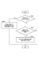
- FIG. 7 is a flowchart illustrating a procedure of processing in which the control device 110 according to the second embodiment automatically excludes an imaging target when there is a radiation detector whose installation status can be limited. Each step in FIG. 7 is executed by the CPU 201 of the control device 110 controlling the radiation imaging system 100 based on the computer program 2031.
- the management unit 216 can be excluded from the radiation detector used for imaging based on the installation status of the radiation detector registered in the radiation imaging system 100 and the radiation generation unit 114 to be used. Determine if exists.
- the determination as to whether or not the radiation detector can be excluded from the radiation detector to be used may be made, for example, based on the installation status of equipment including connection information such as a gantry related to the radiation generation unit 114.
- the radiation generator 114A when the radiation generator 114A is used to irradiate the radiation, only the radiation detector 115A detects the radiation, so the other radiation detectors 115B and 115C are excluded. It corresponds to a radiation detector capable of.
- the radiation generator 114B when the radiation generator 114B is used to irradiate radiation, only the radiation detector 115B detects the radiation, and the other radiation detectors 115A and 115C can be excluded. Hit the vessel.
- the radiation detector 115C detects the radiation, and there are a plurality of radiation detectors corresponding to the radiation detector 115C. For this reason, which radiation detector is used cannot be identified immediately only from the information that the radiation generator 114C is used. However, when using the radiation generator 114C, it is known from the installation status of the devices in the radiation imaging system 100 of FIG. 1 that at least the radiation detectors 115A and 115B are not used. Accordingly, when the radiation generator 114C is used to irradiate radiation, the radiation detectors 115A and 115B correspond to radiation detectors that can be excluded.
- the presence or absence of the radiation detector 115 that can be excluded from the use target is determined based on the installation status of the radiation generation unit 114 and the radiation detector 115.
- a determination is performed using, for example, information indicating a correspondence relationship between the radiation generation unit 114 and the radiation detector 115 used when the radiation generation unit is used in advance. be able to.
- the corresponding radiation detector 115 is identified according to the selection of the radiation generation unit 114 to be used, and it is determined as a radiation detector 115 that can exclude radiation detectors other than the identified radiation detector. it can.
- the information indicating the installation status of the device is not limited to information indicating the correspondence relationship between the devices, and for example, position information of the radiation generation unit 114 and the radiation detector 115, device wiring information, and the like are used. You may do it.
- information indicating a situation where imaging is performed may be used as information indicating the installation status of the device.
- the situation in which such imaging is performed include, for example, the posture of the measurement subject (patient), the usage status of the radiation detector 115 (whether the radiation detector 115 is installed on a gantry or the like, or used in a flat position).
- the correspondence between the situation where imaging is performed such as standing or lying and the radiation detector 115 to be used is stored, and this is handled according to the selection of the situation where imaging is performed.
- You may determine as a radiation detector which can exclude radiation detectors other than a radiation detector.
- a correspondence relationship between the usage status of the radiation detector and the radiation detector 115 to be used such as flat installation or installation on a pedestal, may be stored.
- it can be determined as a radiation detector that can exclude radiation detectors other than the corresponding radiation detector according to the selection of the usage status.
- a radiation generator for imaging a human body in a specific body position or a specific part of the human body is used in this way, a predetermined radiation detector may be excluded from the radiation detector that acquires imaging information. it can.
- the setting unit 215 sets a radiation detector used for imaging that can be excluded from the installation status as an imaging target.
- the setting unit 215 excludes the radiation detector (radiation imaging apparatus) that is disconnected from the radiation detector (radiation imaging apparatus) that acquires imaging information. That is, imaging information is not acquired from the radiation detectors determined as exclusion targets in S501, and imaging information is acquired from other radiation detectors.
- each process of the flowchart of FIG. 7 is completed.
- radiation is generated from any of the radiation generation units 114A, 114B, and 114C in accordance with the operation of the operator with respect to the operation unit 113, and imaged from the radiation detector 115 other than the radiation detectors excluded in S502. Get information.
- the radiation detector which acquires a captured image based on imaging information is selected, and a captured image is acquired from the selected radiation detector.
- the radiation detector can be automatically excluded from the imaging target in accordance with the installation status.
- the time until the transition to the imageable state is made by automatically excluding the radiation detector installed on the gantry or the like from the imaging target. Reduction is expected. Further, since the operator can save the trouble of setting the radiation detector to be excluded from the imaging target, further efficiency improvement of the imaging flow can be expected.
- the imaging inspection information is inspection information indicating the content of the inspection by radiation imaging.
- the imaging examination information is manually input directly to the radiation imaging system 100 by an operation input by an operator, or is automatically input to the radiation imaging system 100 via an external device such as HIS or RIS.
- This imaging examination information includes information including different combinations of the imaging part, imaging body position, imaging direction, etc. of the subject. For this reason, if the imaging body is in an upright position or an upright position, it is clear that a radiation detector installed on a pedestal or table is used, so that it is difficult to make a mistake in selecting a radiation detector.
- a radiation detector that acquires such imaging examination information and acquires imaging information based on the contents is set.
- radiation detectors that are clearly not used are excluded from the objects of use.
- imaging information is acquired only from a necessary radiation detector without acquiring imaging information from an unnecessary radiation detector based on the contents of imaging examination information. Therefore, it is possible to reduce the risk of reduction in imaging efficiency and unnecessary exposure of the human body due to the fact that the radiation detector necessary for detecting the irradiated radiation is not in a detectable state. Accordingly, the time until the transition to the imaging enabled state is reduced.
- FIG. 8 is a flowchart illustrating a processing procedure in which the control device 110 according to the third embodiment automatically sets an imaging target from imaging inspection information. Processes similar to those in FIG. 7 are denoted by the same reference numerals and description thereof is omitted. Each step of FIG. 8 is executed by the CPU 201 of the control device 110 controlling the radiation imaging system 100 based on the computer program 2031.
- step S601 the control unit 211 determines whether the imaging body position is an inspection in which the imaging body is standing or standing. This determination is made based on the content of the imaging inspection information. In the case of an examination in which imaging is performed in the standing position or the standing position (S601; YES), the process proceeds to S602. On the other hand, if it is not an inspection for imaging in the standing position or the standing position (S601; NO), the process proceeds to S501.
- the processing contents after S501 are the same as those in the second embodiment except that the contents of the imaging inspection information are referred to. That is, based on the installation status of the radiation generation unit 114 and the radiation detector 115, the radiation detector 115 that can be excluded from the targets for acquiring imaging information is excluded from the radiation detectors that can be imaged.
- the imaging positions other than the standing position or the lying position are the imaging positions using the flat radiation detector 115 ⁇ / b> C. In this case, since it is not necessary to use the radiation detectors 115A and 115B (YES in S501), these radiation detectors are excluded from the objects of use (S502).
- the setting unit 215 sets a device other than the radiation detector used for imaging as an imaging information acquisition target.
- imaging in the standing position is performed using the radiation generation unit 114A and the radiation detector 115A
- imaging in the lying position is performed using the radiation generation unit 114B and the radiation detector 115B. Therefore, in the case of standing-up imaging, the radiation detectors 115B and 115C other than the radiation detector 115A are excluded from acquisition targets of imaging information. In the case of imaging in the supine position, the radiation detectors 115A and 115C other than the radiation detector 115B are excluded from acquisition targets of imaging information.
- the processes in the flowchart of FIG. 8 are completed.
- the imaging target can be automatically set from the imaging inspection information.
- the imaging position is imaged in a standing position or a recumbent position
- by automatically excluding the radiation detector used for imaging from being the imaging target it is possible to reduce imaging efficiency and useless human body exposure. Risk can be reduced. Accordingly, the time until the transition to the imaging enabled state is reduced.
- the imaging target of the radiation detector may be set by combining the imaging target setting methods implemented in the first to third embodiments as shown in FIG.
- FIG. 9 is a flowchart illustrating a procedure of processing in which the control device 110 sets an imaging target in the present embodiment.
- the same processes as those in FIGS. 6 to 8 are denoted by the same reference numerals, and detailed description thereof is omitted.
- Each step in FIG. 9 is executed by the CPU 201 of the control device 110 controlling the radiation imaging system 100 based on the computer program 2031.
- the processes of S601, S602, S501, and S502 are the same as those in FIG. However, in this embodiment, the process proceeds to S401 after the process of S502.
- the processing of S401 to S403 is the same as that in FIG.
- the radiation detector that acquires the imaging information is excluded based on the content of the imaging examination information.
- radiation detectors that are not likely to be used are excluded from the radiation detectors that acquire imaging information based on the installation status of the radiation generators or radiation detectors.
- the radiation detector for acquiring the imaging information is set in accordance with the operator's instruction.
- user instructions are input in S401 to S403. Therefore, it is possible to easily and reliably set the radiation detector that acquires the imaging information.
- each embodiment of the present invention it is possible to provide a radiation imaging system in which a decrease in imaging efficiency is reduced when there are a large number of radiation detectors used for imaging. Therefore, radiation imaging can be performed efficiently even if all the radiation detectors are not in an imageable state.
- the present invention supplies a program that realizes one or more functions of the above-described embodiments to a system or apparatus via a network or a storage medium, and one or more processors in a computer of the system or apparatus read and execute the program This process can be realized. It can also be realized by a circuit (for example, ASIC) that realizes one or more functions.
- a circuit for example, ASIC
- SYMBOLS 100 Radiation imaging system
- 110 Control apparatus
- 112 Display part
- 113 Operation part
- 114 Radiation generation part
- 115 Radiation detector
- 211 Control part
- 212 Comparison selection part
- 213 Image acquisition part
- 214 Information acquisition unit
- 215 Setting unit
- 216 Management unit
- 217 Setting target input unit
Landscapes
- Health & Medical Sciences (AREA)
- Engineering & Computer Science (AREA)
- Life Sciences & Earth Sciences (AREA)
- Medical Informatics (AREA)
- Biomedical Technology (AREA)
- Public Health (AREA)
- General Health & Medical Sciences (AREA)
- Radiology & Medical Imaging (AREA)
- Nuclear Medicine, Radiotherapy & Molecular Imaging (AREA)
- Animal Behavior & Ethology (AREA)
- Veterinary Medicine (AREA)
- Optics & Photonics (AREA)
- Physics & Mathematics (AREA)
- Heart & Thoracic Surgery (AREA)
- Molecular Biology (AREA)
- Surgery (AREA)
- High Energy & Nuclear Physics (AREA)
- Biophysics (AREA)
- Pathology (AREA)
- Epidemiology (AREA)
- Primary Health Care (AREA)
- Computer Networks & Wireless Communication (AREA)
- Business, Economics & Management (AREA)
- General Business, Economics & Management (AREA)
- Apparatus For Radiation Diagnosis (AREA)
- Measurement Of Radiation (AREA)
Abstract
L'invention concerne un système d'imagerie par rayonnement comprenant : une pluralité de dispositifs d'imagerie destinée à générer des images sur la base d'un rayonnement émis à partir d'un dispositif de génération de rayonnement destiné à émettre un rayonnement ; et un dispositif de commande destiné à communiquer avec la pluralité de dispositifs d'imagerie. Le dispositif de commande comprend : une unité d'acquisition destinée à acquérir des informations d'imagerie à partir de chacun de la pluralité de dispositifs d'imagerie ; une unité de sélection destinée à sélectionner un dispositif d'imagerie parmi la pluralité de dispositifs d'imagerie sur la base des informations d'imagerie acquises dans l'unité d'acquisition ; et une unité d'acquisition d'image destinée à acquérir des images à partir du dispositif d'imagerie sélectionné par l'unité de sélection. Le dispositif de commande comprend en outre une unité de réglage destinée à effectuer des réglages sur les dispositifs d'imagerie à partir desquels l'unité d'acquisition acquiert des informations d'imagerie.
Priority Applications (2)
| Application Number | Priority Date | Filing Date | Title |
|---|---|---|---|
| CN201780063233.8A CN109843177B (zh) | 2016-10-14 | 2017-09-29 | 放射线摄像系统及其控制方法、控制装置及介质 |
| US16/379,954 US10987079B2 (en) | 2016-10-14 | 2019-04-10 | Radiation imaging system, method of controlling the same, control apparatus, and storage medium |
Applications Claiming Priority (2)
| Application Number | Priority Date | Filing Date | Title |
|---|---|---|---|
| JP2016-203040 | 2016-10-14 | ||
| JP2016203040A JP6912878B2 (ja) | 2016-10-14 | 2016-10-14 | 放射線撮像システム及びその制御方法、制御装置及びその制御方法、コンピュータプログラム |
Related Child Applications (1)
| Application Number | Title | Priority Date | Filing Date |
|---|---|---|---|
| US16/379,954 Continuation US10987079B2 (en) | 2016-10-14 | 2019-04-10 | Radiation imaging system, method of controlling the same, control apparatus, and storage medium |
Publications (1)
| Publication Number | Publication Date |
|---|---|
| WO2018070272A1 true WO2018070272A1 (fr) | 2018-04-19 |
Family
ID=61905664
Family Applications (1)
| Application Number | Title | Priority Date | Filing Date |
|---|---|---|---|
| PCT/JP2017/035485 Ceased WO2018070272A1 (fr) | 2016-10-14 | 2017-09-29 | Système d'imagerie par rayonnement et son procédé de commande, dispositif de commande et son procédé de commande, et programme informatique |
Country Status (4)
| Country | Link |
|---|---|
| US (1) | US10987079B2 (fr) |
| JP (1) | JP6912878B2 (fr) |
| CN (1) | CN109843177B (fr) |
| WO (1) | WO2018070272A1 (fr) |
Families Citing this family (4)
| Publication number | Priority date | Publication date | Assignee | Title |
|---|---|---|---|---|
| CN109843178B (zh) * | 2016-10-14 | 2023-07-28 | 佳能株式会社 | 放射线摄像系统、摄像装置、控制装置、控制方法和介质 |
| JP6786411B2 (ja) | 2017-02-08 | 2020-11-18 | キヤノン株式会社 | 放射線撮影システム、携帯情報端末、放射線撮影方法、及びプログラム |
| JP7455729B2 (ja) * | 2020-10-30 | 2024-03-26 | 富士フイルム株式会社 | 情報処理装置、放射線検出器、情報処理方法、及び情報処理プログラム |
| JP7835586B2 (ja) * | 2022-03-18 | 2026-03-25 | 富士フイルム株式会社 | 撮影管理装置、撮影管理装置の作動方法、および撮影管理装置の作動プログラム |
Citations (4)
| Publication number | Priority date | Publication date | Assignee | Title |
|---|---|---|---|---|
| WO2010073894A1 (fr) * | 2008-12-24 | 2010-07-01 | コニカミノルタエムジー株式会社 | Appareil portable de capture d'images radiologiques et système |
| JP2011177348A (ja) * | 2010-03-01 | 2011-09-15 | Fujifilm Corp | 放射線画像取得装置、放射線画像撮影システム及び放射線画像撮影方法 |
| JP2011177347A (ja) * | 2010-03-01 | 2011-09-15 | Fujifilm Corp | 放射線画像取得装置、放射線画像撮影システム及び放射線画像撮影方法 |
| JP2015062468A (ja) * | 2013-09-24 | 2015-04-09 | 株式会社島津製作所 | 放射線撮影装置 |
Family Cites Families (2)
| Publication number | Priority date | Publication date | Assignee | Title |
|---|---|---|---|---|
| CN101137327B (zh) * | 2005-03-10 | 2010-09-29 | 柯尼卡美能达医疗印刷器材株式会社 | 放射线图像成像系统 |
| JP2013180061A (ja) | 2012-03-01 | 2013-09-12 | Canon Inc | 情報処理装置、その制御方法及びプログラム |
-
2016
- 2016-10-14 JP JP2016203040A patent/JP6912878B2/ja active Active
-
2017
- 2017-09-29 CN CN201780063233.8A patent/CN109843177B/zh active Active
- 2017-09-29 WO PCT/JP2017/035485 patent/WO2018070272A1/fr not_active Ceased
-
2019
- 2019-04-10 US US16/379,954 patent/US10987079B2/en active Active
Patent Citations (4)
| Publication number | Priority date | Publication date | Assignee | Title |
|---|---|---|---|---|
| WO2010073894A1 (fr) * | 2008-12-24 | 2010-07-01 | コニカミノルタエムジー株式会社 | Appareil portable de capture d'images radiologiques et système |
| JP2011177348A (ja) * | 2010-03-01 | 2011-09-15 | Fujifilm Corp | 放射線画像取得装置、放射線画像撮影システム及び放射線画像撮影方法 |
| JP2011177347A (ja) * | 2010-03-01 | 2011-09-15 | Fujifilm Corp | 放射線画像取得装置、放射線画像撮影システム及び放射線画像撮影方法 |
| JP2015062468A (ja) * | 2013-09-24 | 2015-04-09 | 株式会社島津製作所 | 放射線撮影装置 |
Also Published As
| Publication number | Publication date |
|---|---|
| CN109843177B (zh) | 2024-06-11 |
| JP2018061784A (ja) | 2018-04-19 |
| US10987079B2 (en) | 2021-04-27 |
| CN109843177A (zh) | 2019-06-04 |
| JP6912878B2 (ja) | 2021-08-04 |
| US20190231295A1 (en) | 2019-08-01 |
Similar Documents
| Publication | Publication Date | Title |
|---|---|---|
| JP7106718B2 (ja) | 放射線撮影装置、放射線撮影システム、放射線撮影方法、及びプログラム | |
| WO2020209289A1 (fr) | Système d'imagerie radiographique | |
| US10485504B2 (en) | Radiographing system for obtaining a dose index from a generated composition image | |
| JP6104618B2 (ja) | X線診断装置及び制御プログラム | |
| WO2015064011A1 (fr) | Dispositif de commande d'imagerie, dispositif d'imagerie radiographique, procédé de commande d'imagerie, et programme | |
| WO2018070272A1 (fr) | Système d'imagerie par rayonnement et son procédé de commande, dispositif de commande et son procédé de commande, et programme informatique | |
| US12465309B2 (en) | Imaging support device, and operation method and operation program for the same | |
| JP2024161485A (ja) | 写損判断支援装置及びプログラム | |
| JP4938483B2 (ja) | 放射線撮像システム、放射線撮像方法、及びプログラム | |
| US11538187B2 (en) | Radiographic system, radiographic method, and storage medium | |
| JP5847406B2 (ja) | 医療システム | |
| US20230326579A1 (en) | Image diagnosis support device, operation method for image diagnosis support device, and program | |
| US20230005105A1 (en) | Radiation imaging system, image processing method, and storage medium | |
| JP2015173803A (ja) | 撮影者割り当て装置、撮影者割り当て装置の制御方法、撮影者割り当てプログラム、及び撮影者割り当てシステム | |
| JP7835692B2 (ja) | 画像診断支援装置、画像診断支援装置の作動方法、及びプログラム | |
| JP2014046077A (ja) | X線撮影装置 | |
| JP5614950B2 (ja) | 放射線撮影装置、放射線撮影の制御方法、及び、プログラム | |
| JP2012130369A (ja) | 検像装置及び検像システム | |
| JP2013000260A (ja) | 放射線画像撮影装置および方法 | |
| JP6860050B2 (ja) | 放射線撮影システム、撮影制御装置、放射線撮影方法及び放射線撮影プログラム | |
| JP2008246033A (ja) | 医用画像処理装置、医用画像処理方法及びプログラム | |
| JP2015073658A (ja) | 画像表示装置及び距離算出方法 | |
| JP2025158400A (ja) | 画像処理装置および動態画像における角度計測方法 | |
| JP5423914B2 (ja) | 放射線画像生成システム | |
| JP2020089593A (ja) | 医用情報処理装置、医用情報処理方法及びプログラム |
Legal Events
| Date | Code | Title | Description |
|---|---|---|---|
| 121 | Ep: the epo has been informed by wipo that ep was designated in this application |
Ref document number: 17859801 Country of ref document: EP Kind code of ref document: A1 |
|
| NENP | Non-entry into the national phase |
Ref country code: DE |
|
| 122 | Ep: pct application non-entry in european phase |
Ref document number: 17859801 Country of ref document: EP Kind code of ref document: A1 |