WO2018073899A1 - Système informatique, procédé de diagnostic de plante, et programme - Google Patents
Système informatique, procédé de diagnostic de plante, et programme Download PDFInfo
- Publication number
- WO2018073899A1 WO2018073899A1 PCT/JP2016/080871 JP2016080871W WO2018073899A1 WO 2018073899 A1 WO2018073899 A1 WO 2018073899A1 JP 2016080871 W JP2016080871 W JP 2016080871W WO 2018073899 A1 WO2018073899 A1 WO 2018073899A1
- Authority
- WO
- WIPO (PCT)
- Prior art keywords
- visible light
- plant
- light image
- region
- temperature
- Prior art date
- Legal status (The legal status is an assumption and is not a legal conclusion. Google has not performed a legal analysis and makes no representation as to the accuracy of the status listed.)
- Ceased
Links
Images




Classifications
-
- G—PHYSICS
- G01—MEASURING; TESTING
- G01N—INVESTIGATING OR ANALYSING MATERIALS BY DETERMINING THEIR CHEMICAL OR PHYSICAL PROPERTIES
- G01N33/00—Investigating or analysing materials by specific methods not covered by groups G01N1/00 - G01N31/00
- G01N33/0098—Plants or trees
-
- G—PHYSICS
- G01—MEASURING; TESTING
- G01N—INVESTIGATING OR ANALYSING MATERIALS BY DETERMINING THEIR CHEMICAL OR PHYSICAL PROPERTIES
- G01N21/00—Investigating or analysing materials by the use of optical means, i.e. using sub-millimetre waves, infrared, visible or ultraviolet light
- G01N21/17—Systems in which incident light is modified in accordance with the properties of the material investigated
- G01N21/25—Colour; Spectral properties, i.e. comparison of effect of material on the light at two or more different wavelengths or wavelength bands
- G01N21/31—Investigating relative effect of material at wavelengths characteristic of specific elements or molecules, e.g. atomic absorption spectrometry
- G01N21/35—Investigating relative effect of material at wavelengths characteristic of specific elements or molecules, e.g. atomic absorption spectrometry using infrared light
- G01N21/3563—Investigating relative effect of material at wavelengths characteristic of specific elements or molecules, e.g. atomic absorption spectrometry using infrared light for analysing solids; Preparation of samples therefor
-
- G—PHYSICS
- G01—MEASURING; TESTING
- G01N—INVESTIGATING OR ANALYSING MATERIALS BY DETERMINING THEIR CHEMICAL OR PHYSICAL PROPERTIES
- G01N25/00—Investigating or analyzing materials by the use of thermal means
- G01N25/72—Investigating presence of flaws
-
- G—PHYSICS
- G06—COMPUTING OR CALCULATING; COUNTING
- G06Q—INFORMATION AND COMMUNICATION TECHNOLOGY [ICT] SPECIALLY ADAPTED FOR ADMINISTRATIVE, COMMERCIAL, FINANCIAL, MANAGERIAL OR SUPERVISORY PURPOSES; SYSTEMS OR METHODS SPECIALLY ADAPTED FOR ADMINISTRATIVE, COMMERCIAL, FINANCIAL, MANAGERIAL OR SUPERVISORY PURPOSES, NOT OTHERWISE PROVIDED FOR
- G06Q50/00—Information and communication technology [ICT] specially adapted for implementation of business processes of specific business sectors, e.g. utilities or tourism
- G06Q50/02—Agriculture; Fishing; Forestry; Mining
-
- G—PHYSICS
- G06—COMPUTING OR CALCULATING; COUNTING
- G06T—IMAGE DATA PROCESSING OR GENERATION, IN GENERAL
- G06T7/00—Image analysis
- G06T7/0002—Inspection of images, e.g. flaw detection
- G06T7/0012—Biomedical image inspection
-
- G—PHYSICS
- G06—COMPUTING OR CALCULATING; COUNTING
- G06T—IMAGE DATA PROCESSING OR GENERATION, IN GENERAL
- G06T7/00—Image analysis
- G06T7/10—Segmentation; Edge detection
-
- G—PHYSICS
- G06—COMPUTING OR CALCULATING; COUNTING
- G06T—IMAGE DATA PROCESSING OR GENERATION, IN GENERAL
- G06T7/00—Image analysis
- G06T7/90—Determination of colour characteristics
-
- A—HUMAN NECESSITIES
- A01—AGRICULTURE; FORESTRY; ANIMAL HUSBANDRY; HUNTING; TRAPPING; FISHING
- A01G—HORTICULTURE; CULTIVATION OF VEGETABLES, FLOWERS, RICE, FRUIT, VINES, HOPS OR SEAWEED; FORESTRY; WATERING
- A01G7/00—Botany in general
-
- G—PHYSICS
- G06—COMPUTING OR CALCULATING; COUNTING
- G06T—IMAGE DATA PROCESSING OR GENERATION, IN GENERAL
- G06T2207/00—Indexing scheme for image analysis or image enhancement
- G06T2207/10—Image acquisition modality
- G06T2207/10024—Color image
-
- G—PHYSICS
- G06—COMPUTING OR CALCULATING; COUNTING
- G06T—IMAGE DATA PROCESSING OR GENERATION, IN GENERAL
- G06T2207/00—Indexing scheme for image analysis or image enhancement
- G06T2207/10—Image acquisition modality
- G06T2207/10048—Infrared image
Definitions
- the present invention relates to a computer system that performs imaging by imaging a plant, a plant diagnosis method, and a program.
- Non-Patent Document 1 a configuration is disclosed in which disease diagnosis is performed by measuring changes in plant temperature and color using a spectrometer or infrared thermography (see Non-Patent Document 1).
- Non-Patent Document 1 there is a temperature difference for each part of the plant, and in order to accurately grasp the disease state, it is possible to accurately measure the temperature of each part to be measured. It has been demanded. However, although it is possible to specify the outline of a plant and an approximate site from a thermographic image, it is difficult to specify the exact position of each site depending on the distance from the camera to the subject and other factors. As a result, there was a limit to improving the accuracy of the temperature measured for each part.
- An object of the present invention is to provide a computer system, a plant diagnosis method, and a program in which the temperature measurement accuracy of each target part is improved.
- the present invention provides the following solutions.
- the present invention includes first acquisition means for acquiring a visible light image and an infrared image captured by a camera; A first image processing means for identifying a region corresponding to a predetermined part of the plant imaged by the camera in the visible light image; Second image processing means for identifying a region in the infrared image corresponding to the identified region in the visible light image; Diagnostic means for diagnosing the plant based on the temperature of the region in the identified infrared image; A computer system is provided.
- a visible light image and an infrared image captured by a camera are acquired, and a region corresponding to a predetermined part of a plant captured by the camera is identified and identified in the visible light image.
- the region in the infrared image corresponding to the region in the visible light image thus identified is identified, and the plant is diagnosed based on the temperature of the region in the identified infrared image.
- the present invention is a computer system category, but also in other categories such as a plant diagnosis method and program, the same actions and effects according to the category are exhibited.
- FIG. 1 is a diagram showing an outline of a plant diagnosis system 1.
- FIG. 2 is an overall configuration diagram of the plant diagnosis system 1.
- FIG. 3 is a functional block diagram of the computer 10.
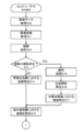
- FIG. 4 is a flowchart showing a plant diagnosis process executed by the computer 10.
- FIG. 5 is a flowchart showing a plant diagnosis process executed by the computer 10.
- FIG. 6 is a diagram schematically showing an example of visible light image data acquired by the computer 10.
- FIG. 7 is a diagram schematically showing an example of infrared image data acquired by the computer 10.
- FIG. 8 is a diagram illustrating an example schematically showing a state in which the computer 10 specifies a predetermined part in a visible light image.
- FIG. 9 is a diagram schematically illustrating an example in which the computer 10 specifies a region in an infrared image.
- FIG. 10 is a diagram illustrating an example of a reference temperature database stored in the computer 10.
- FIG. 1 is a diagram for explaining an outline of a plant diagnosis system 1 which is a preferred embodiment of the present invention.
- the plant diagnosis system 1 includes a computer 10 and acquires an image obtained by capturing an image of a plant and diagnoses the plant.
- the computer 10 is a computing device that is communicably connected to a visible light camera, an infrared camera, a sensor, an environment adjustment device, etc. (not shown).
- the plant diagnosis system 1 obtains a visible light image from a visible light camera, obtains an infrared image from an infrared camera, and the environment about the living environment of the plant such as illuminance, wind direction, wind speed, temperature, temperature, humidity, and atmospheric pressure from the sensor.
- Information is acquired and the instruction
- the computer 10 acquires a visible light image and an infrared image captured by a camera (not shown) (step S01).
- the computer 10 acquires a visible light image such as a moving image or a still image of a plant captured by the visible light camera.
- the computer 10 acquires an infrared image such as a moving image or a still image of a plant imaged by the infrared camera.
- the visible light camera and the infrared camera are installed side by side or in the vicinity, and the visible light camera and the infrared camera image the same object. That is, the visible light camera and the infrared camera image the same object from substantially the same imaging point.
- the computer 10 specifies a visible light image region that is a region corresponding to a predetermined part of the plant imaged by the camera in the visible light image (step S02).
- the computer 10 specifies, for example, a part of a structure such as a flower, a branch, a leaf, or a preset part as the predetermined part of the plant.
- the computer 10 specifies an area corresponding to the predetermined part in the visible light image by image analysis.
- the computer 10 extracts a feature amount existing in the visible light image, and specifies a predetermined part based on the feature amount.
- the computer 10 extracts the color of the visible light image and identifies a predetermined part based on this color.
- the computer 10 specifies an infrared image region that is a region in the infrared image corresponding to the region in the visible light image described above in the infrared image (step S03).
- the computer 10 compares the visible light image and the infrared image, and identifies the region that matches the visible light image region in the infrared image as the infrared image region.
- the computer 10 identifies an infrared image area at the same position as the visible light image area as the infrared image area.
- the computer 10 diagnoses a plant based on the temperature of the infrared image area (step S04).
- the computer 10 diagnoses whether or not a disease has occurred in the plant, for example, by comparing the temperature of the infrared image region with the temperature at the time of the disease of the plant.
- FIG. 2 is a diagram showing a system configuration of the plant diagnosis system 1 which is a preferred embodiment of the present invention.
- the plant diagnosis system 1 includes a computer 10 and a public line network (Internet network, third generation, fourth generation communication network, etc.) 5, acquires an image of a plant, and diagnoses the plant.
- Internet network Internet network, third generation, fourth generation communication network, etc.
- the plant diagnostic system 1 is a camera such as a visible light camera that captures a visible light image of a plant and an infrared camera that captures an infrared image of a plant, and the living environment of the plant such as illuminance, wind light, wind speed, temperature, temperature, humidity, and atmospheric pressure. It is connected to an environmental adjustment device that adjusts the living environment of a plant such as various sensors that detect environmental information, lighting devices such as various lights, air conditioners such as blowers, watering devices, and chemical spraying devices. The computer 10 obtains various information from these and transmits various instructions.
- the computer 10 is the above-described computing device having the functions described later.
- FIG. 3 is a functional block diagram of the computer 10.
- the computer 10 includes a CPU (Central Processing Unit), a RAM (Random Access Memory), a ROM (Read Only Memory), and the like as the control unit 11, and other devices (cameras, various sensors, environmental adjustment devices) as the communication unit 12. Etc.), for example, a WiFi (Wireless Fidelity) compatible device compliant with IEEE 802.11.
- the computer 10 also includes a data storage unit such as a hard disk, a semiconductor memory, a recording medium, or a memory card as the storage unit 13. Further, the computer 10 includes, as the processing unit 14, a device for executing various processes such as image processing and disease diagnosis.
- the control unit 11 when the control unit 11 reads a predetermined program, the image data acquisition module 20, the environment information acquisition module 21, and the adjustment instruction transmission module 22 are realized in cooperation with the communication unit 12. Further, in the computer 10, the control unit 11 reads a predetermined program, thereby realizing the storage module 30 in cooperation with the storage unit 13. Further, in the computer 10, the control unit 11 reads a predetermined program, so that the visible light image analysis module 40, the infrared image analysis module 41, the temperature analysis module 42, the diagnosis module 43, and the environment cooperate with the processing unit 14. The adjustment module 44 is realized.
- the image data acquisition module 20 acquires image data of a visible light image and an infrared image of a plant (step S10).
- the image data acquisition module 20 acquires visible light image data that is a visible light image captured by the visible light camera and infrared image data that is an infrared image captured by the infrared camera.
- the image data acquisition module 20 acquires visible light image data and infrared image data at a predetermined time interval or at a plurality of time points such as a preset time.
- the visible light image data and the infrared image data acquired by the image data acquisition module 20 are captured from the same imaging viewpoint and are the same target data.
- the computer 10 executes plant diagnosis based on visible light image data and infrared image data at a predetermined time.
- FIG. 6 is a diagram schematically illustrating an example of visible light image data acquired by the image data acquisition module 20.
- the image data acquisition module 20 acquires the visible light image 100 indicated by the visible light image data.
- a plant 110 is shown.
- the visible light image 100 may include landscapes, natural objects, artificial objects, and the like other than the plants 110, but are omitted for the sake of simplicity.
- a plurality of plants 110 and plants different from the plants 110 may exist in the visible light image 100.
- FIG. 7 is a diagram schematically showing an example of infrared image data acquired by the image data acquisition module 20.
- the image data acquisition module 20 acquires an infrared image 200 indicated by the infrared image data.
- the plant 210 is reflected in the infrared image 200.
- the infrared image 200 may include scenery, natural objects, artifacts, and the like other than the plant 210, but are omitted for the sake of simplicity.
- each temperature is indicated by hatching for convenience.
- the infrared image 200 may include a plurality of plants 210 and plants different from the plants 210.
- the environment information acquisition module 21 acquires environment information indicating the living environment of the plant (step S11).
- the environment information acquisition module 21 acquires illuminance, wind light, wind speed, temperature, temperature, humidity, atmospheric pressure, and the like as environment information.
- the environment information acquisition module 21 acquires environment information from various sensors (not shown) such as an illuminance sensor, a wind direction / wind speed sensor, a temperature sensor, a humidity sensor, and a pressure sensor.
- the environment information acquisition module 21 acquires the visible light image data and the infrared image data at the same time as the acquisition timing. These various sensors are installed in the vicinity of the plant or in the vicinity of the place where the plant is planted.
- the various sensors may be sensors that detect environmental information other than the examples described above.
- the installation position of various sensors is not restricted to the example mentioned above, It can change suitably to the position which can detect the living environment of this plant.
- the process of step S11 may be omitted. In this case, what is necessary is just to perform the process of step S12 mentioned later after performing the process of step S10 mentioned above.
- the visible light image analysis module 40 performs image analysis on the acquired visible light image data (step S12).
- step S ⁇ b> 12 the visible light image analysis module 40 extracts feature amounts and colors of the visible light image data, and identifies plants existing in the visible light image data.
- step S12 for example, the visible light image analysis module 40 compares the feature quantity extracted from the visible light image data with the feature quantity of the plant stored in advance in the storage module 30, and extracts a plant having a matching feature quantity. The extracted plant is identified as existing in the visible light image data. Further, for example, the visible light image analysis module 40 compares the RGB value extracted from the visible light image data with the RGB value of the plant stored in the storage module 30 in advance, and extracts a plant having a matching or similar RGB value. The extracted plant is identified as existing in the visible light image data.
- the visible light image analysis module 40 determines whether there are a plurality of individuals in the visible light image data as a result of the image analysis (step S13). In step S13, the visible light image analysis module 40 determines whether there are a plurality of individuals by determining whether there are a plurality of plants in the visible light image data. The visible light image analysis module 40 determines whether there are a plurality of individuals of one plant, whether there are a plurality of types of plants, or the like.
- step S13 when the visible light image analysis module 40 determines that there are not a plurality of individuals (step S13: NO), that is, when it is determined that only one individual is present in the visible light image data, visible light image analysis is performed.
- the module 40 identifies areas corresponding to a plurality of predetermined parts of one individual (step S14).
- the predetermined part is, for example, a part of a structure such as a flower, a branch, or a leaf, or a part that is set in advance.
- the visible light image analysis module 40 identifies areas corresponding to, for example, flowers, branches, and leaves.
- the visible light image analysis module 40 extracts flowers, branches, and leaves present in the visible light image data from the feature amount, and specifies the extracted location as a region corresponding to a predetermined part. At this time, the visible light image analysis module 40 specifies a plurality of regions corresponding to each of the plurality of predetermined parts. Further, the visible light image analysis module 40 extracts flowers, branches, and leaves present in the visible light image data from the RGB values, and specifies the extracted location as an area corresponding to a predetermined part.
- FIG. 8 is a diagram illustrating an example schematically showing a state in which the visible light image analysis module 40 specifies a predetermined part.
- the visible light image analysis module 40 identifies a region in the visible light image 100 where a predetermined part such as a flower, a branch, or a leaf is located based on the feature amount or the color.
- the visible light image analysis module 40 identifies regions of the plant 110 corresponding to the parts of the flowers 300 to 302, the branches 310 to 312 and the leaves 320 to 322.
- the specified area is indicated by hatching for convenience. This area indicates a part of each part, but may indicate the entire corresponding part. Note that the number, type, and position of the parts to be specified can be changed as appropriate.
- step S13 the visible light image analysis module 40 determines that there are a plurality of individuals (YES in step S13), that is, a plurality of individuals such as a first individual, a second individual, and a third individual.
- the visible light image analysis module 40 identifies each of the plurality of individuals (step S15). In the following description, it will be assumed that the first individual and the second individual exist in the visible light image data.
- the visible light image analysis module 40 identifies the positional relationship of each of the plurality of individuals (step S16).
- step S ⁇ b> 16 the visible light image analysis module 40 identifies the positional relationship between the first individual and the second individual based on the position in the visible light image.
- the visible light image analysis module 40 specifies a relative position or an absolute position between the first individual and the second individual.
- the positional relationship is, for example, which is closer to the shooting point, coordinates in the visible light image, or the like. Note that the processing in step S16 is not limited to the positional relationship between the first individual and the second individual, but may be the positional relationship with other individuals.
- the visible light image analysis module 40 specifies a region corresponding to a predetermined part for each of the plurality of individuals (step S17).
- the process of step S17 performs the process of step S14 mentioned above with respect to each plant which exists in visible light image data.
- the infrared image analysis module 41 identifies a region in the infrared image corresponding to the region in the identified visible light image (step S18).
- the infrared image analysis module 41 compares the visible light image data with the infrared image data to identify the region of the infrared image data corresponding to the identified region of the plant part.
- the infrared image analysis module 41 acquires the position of the region in the visible light image as a coordinate, and specifies the position that matches the acquired coordinate as the region in the infrared image corresponding to the region in the identified visible light image.
- FIG. 9 is a diagram illustrating an example schematically showing a state in which the infrared image analysis module 41 specifies a region in the infrared image.
- the region in the infrared image 200 corresponding to the parts of the flowers 300 to 302, branches 310 to 312 and leaves 320 to 322 of the specified plant 110 is specified. This is specified by comparing the position in the visible light image 100 and the position in the infrared image 200.
- the infrared image analysis module 41 acquires the position coordinates of each part in the visible light image 100, and specifies the position in the infrared image corresponding to the acquired position coordinates as the region in the infrared image corresponding to the region in the visible light image. .
- the infrared image analysis module 41 identifies the parts of the flowers 210 to 402, branches 410 to 412 and leaves 420 to 422 of the plant 210.
- the specified area is indicated by hatching for convenience. This area refers to a part or the whole part depending on the part specified in the above-described visible light image. Note that the number of positions to be specified and their positions can be changed as appropriate in accordance with the visible light image.
- the temperature analysis module 42 analyzes the temperature of the area in the specified infrared image data (step S19). In step S19, the temperature analysis module 42 acquires the temperature of each region based on the infrared image data.
- the temperature analysis module 42 acquires a plurality of reference temperatures corresponding to each of the plurality of parts of the plant from the reference temperature database stored in the storage module 30 (step S20).
- the storage module 30 stores a plurality of reference temperatures corresponding to the respective parts in advance, and the temperature analysis module 42 acquires the stored reference temperatures.
- the reference temperature of the part corresponding to the region in the specified infrared image data is acquired.
- FIG. 10 is a diagram illustrating an example of a reference temperature database stored in the storage module 30.
- the storage module 30 stores the name of the part and the reference temperature of the part in association with each other. That is, the storage module 30 associates “stem” with “18”, associates “branch” with “17”, and associates “leaf” with “20”.
- the storage module 30 stores this reference temperature database for each type of plant.
- the storage module 30 may store a reference temperature database for each individual plant, not for each plant type. In this case, the storage module 30 may acquire a reference temperature for each part of each individual in advance and store the part and the reference temperature in association with each other.
- the diagnosis module 43 diagnoses a plant based on the temperature of the region in the identified infrared image (step S21).
- the diagnosis module 43 performs the diagnosis of the plant on the acquired temperature, the reference temperature, the temperature of another individual different from the one individual, the positional relationship between the first individual and the second individual, and the environmental information. It is executed by any one or a plurality of combinations.
- the diagnosis module 43 executes plant diagnosis based on the acquired temperature will be described.
- the diagnosis module 43 determines whether or not the temperature of the region in the specified infrared image is an abnormal value, and determines that it is healthy if the temperature is not an abnormal value. On the other hand, if the diagnosis module 43 determines that the value is an abnormal value, it determines that a disease has occurred.
- the diagnosis module 43 executes plant diagnosis at a reference temperature.
- the diagnosis module 43 compares the temperature of the region in the identified infrared image with the reference temperature stored in the acquired storage module 30, and calculates the temperature difference between the temperature of the region and the reference temperature.
- the diagnosis module 43 determines whether the calculated temperature difference is within a predetermined range (for example, within 0.5 ° C, within 1 ° C, within 2 ° C, etc.). It is judged that. On the other hand, the diagnosis module 43 determines that a disease has occurred when the calculated temperature difference is not within the predetermined range.
- the diagnosis module 43 performs plant diagnosis based on one individual and the temperature of another individual different from the one individual.
- the diagnostic module 43 compares the temperature of the region in the infrared image of the acquired one individual with the temperature of the corresponding region of the same part in the infrared image of another individual different from the one individual. Calculate the temperature difference.
- the diagnosis module 43 determines whether the calculated temperature difference is within a predetermined range (for example, within 0.5 ° C, within 1 ° C, within 2 ° C, etc.). It is judged that. On the other hand, the diagnostic module 43 determines that a disease has occurred when the calculated temperature difference is not within the predetermined range.
- the diagnosis module 43 compares the reference temperature described above with one individual or another individual, and calculates a temperature difference between the one individual and another individual, thereby causing a disease. It may be determined whether or not the above has occurred. That is, the diagnosis module 43 may determine whether a disease has occurred in one or both of one individual or another individual based on the reference temperature and the temperature difference.
- the diagnosis module 43 executes plant diagnosis based on the positional relationship between the first individual and the second individual.
- the diagnosis module 43 compares the positional relationship between the position of the first individual and the second individual that is different from the first individual among the plurality of acquired individuals, and one of them is such as sunlight or lighting. Determine if you are more affected. This is to identify whether either the first individual or the second individual has a higher temperature due to the influence of sunlight, lighting, or the like.
- the diagnosis module 43 corrects the temperatures of the first and second individuals by acquiring environmental information such as the temperature and illuminance for the influence of sunlight and lighting.
- the diagnosis module 43 compares the corrected temperatures of the first individual and the second individual with the reference temperature described above, and calculates the temperature difference between them.
- the diagnosis module 43 determines whether or not the temperature difference is within a predetermined range (for example, within 0.5 ° C., within 1 ° C., within 2 ° C., etc.). Judge that there is. On the other hand, when the diagnosis module 43 determines that the calculated temperature difference is not within the predetermined range, it determines that a disease has occurred.
- the diagnostic module 43 may determine whether or not the patient is healthy without using the reference temperature. For example, what is necessary is just to judge whether it is healthy based on whether the temperature of the corrected 1st individual
- the diagnosis module 43 executes plant diagnosis based on environmental information acquired from a sensor will be described.
- the diagnosis module 43 corrects the acquired individual temperature based on the environmental information. For example, the diagnosis module 43 acquires humidity, air temperature, atmospheric pressure, and the like as environment information, and corrects the acquired individual temperature based on the acquired environment information.
- the diagnosis module 43 diagnoses a plant based on the corrected individual temperature.
- the diagnostic module 43 may determine whether or not the plant is healthy based on the corrected individual temperature and the reference temperature.
- the diagnosis module 43 outputs a diagnosis result (step S22).
- the diagnosis module 43 outputs the contents of the disease (for example, the name of the disease, a countermeasure method, etc.) as the diagnosis result.
- the diagnosis module 43 outputs the diagnosis result of the one individual.
- the diagnosis module 43 outputs a diagnosis result for each individual.
- the diagnosis module 43 outputs a diagnosis result together with various information capable of uniquely specifying the individual such as the name, identifier, and position information of each individual.
- the diagnosis module 43 performs plant diagnosis using one visible light image data and one infrared image data, but a plurality of visible light image data acquired within a predetermined period. Further, plant diagnosis may be executed based on the infrared image data. In this case, plant diagnosis may be executed based on the change amount, change width, or change itself of the temperature of the individual obtained from each infrared image data. Moreover, the diagnosis module 43 should just perform the diagnosis of this plant with the average value of the temperature of the individual
- the diagnosis module 43 calculates a temperature difference between the average value of the individual and the reference temperature by comparing the average value of the temperature of the individual with the reference temperature, and the temperature difference is a predetermined value.
- the diagnosis of the plant may be executed based on whether it is within the range.
- the diagnosis module 43 determines whether a disease has occurred in the individual based on the output diagnosis result (step S23).
- step S23 when the diagnosis module 43 determines that no disease has occurred in the individual (NO in step S23), the process ends. At this time, the diagnosis module 43 may transmit a notification to the effect that no disease has occurred in the individual to an external terminal device (not shown).
- step S23 when the diagnosis module 43 determines that a disease has occurred in the individual (YES in step S23), the environment adjustment module 44 adjusts the living environment based on information representing the result of the diagnosis.
- An instruction is created (step S24).
- step S24 the environment adjustment module 44 acquires a necessary process based on the diagnosed disease content based on an adjustment database that stores the disease content and the process in association with each other.
- the environment adjustment module 44 creates an adjustment instruction for executing the acquired processing.
- This adjustment instruction includes necessary processing and information that can uniquely identify the environmental adjustment device such as an identifier or device ID of the environmental adjustment device that executes this processing.
- the adjustment instruction transmission module 22 transmits the adjustment instruction created by the environment adjustment module 44 in step S24 described above to the environment adjustment apparatus (step S25).
- the adjustment instruction transmission module 22 transmits the environmental adjustment device included in the adjustment instruction to the target environmental adjustment device based on information that can uniquely identify the environmental adjustment device.
- the environment adjustment device receives this adjustment instruction and executes necessary processing included in this adjustment instruction. For example, the environment adjustment device executes lighting on / off, humidity and temperature control, watering, medicine spraying, and the like.
- the above is the plant diagnosis process.
- the computer 10 executes a process of determining a plant disease, but the present invention can also be applied to diagnosis of other plants.
- the computer 10 may execute a process of determining the necessity of watering based on the temperature of the plant described above, or determines the necessity of adjusting the illuminance based on the temperature of the plant and the environmental information.
- the process to perform may be performed, and another process may be performed.
- the means and functions described above are realized by a computer (including a CPU, an information processing apparatus, and various terminals) reading and executing a predetermined program.
- the program is provided, for example, in a form (SaaS: Software as a Service) provided from a computer via a network.
- the program is provided in a form recorded on a computer-readable recording medium such as a flexible disk, CD (CD-ROM, etc.), DVD (DVD-ROM, DVD-RAM, etc.).
- the computer reads the program from the recording medium, transfers it to the internal storage device or the external storage device, stores it, and executes it.
- the program may be recorded in advance in a storage device (recording medium) such as a magnetic disk, an optical disk, or a magneto-optical disk, and provided from the storage device to a computer via a communication line.
Landscapes
- Engineering & Computer Science (AREA)
- Physics & Mathematics (AREA)
- Life Sciences & Earth Sciences (AREA)
- General Physics & Mathematics (AREA)
- Health & Medical Sciences (AREA)
- General Health & Medical Sciences (AREA)
- Theoretical Computer Science (AREA)
- Chemical & Material Sciences (AREA)
- Computer Vision & Pattern Recognition (AREA)
- Biochemistry (AREA)
- Pathology (AREA)
- Analytical Chemistry (AREA)
- Immunology (AREA)
- Botany (AREA)
- Spectroscopy & Molecular Physics (AREA)
- Quality & Reliability (AREA)
- Radiology & Medical Imaging (AREA)
- Food Science & Technology (AREA)
- Nuclear Medicine, Radiotherapy & Molecular Imaging (AREA)
- Wood Science & Technology (AREA)
- Medicinal Chemistry (AREA)
- Medical Informatics (AREA)
- Business, Economics & Management (AREA)
- Environmental Sciences (AREA)
- Forests & Forestry (AREA)
- Ecology (AREA)
- Biodiversity & Conservation Biology (AREA)
- Animal Husbandry (AREA)
- Marine Sciences & Fisheries (AREA)
- Mining & Mineral Resources (AREA)
- Agronomy & Crop Science (AREA)
- Economics (AREA)
- Human Resources & Organizations (AREA)
- Marketing (AREA)
- Primary Health Care (AREA)
- Strategic Management (AREA)
- Tourism & Hospitality (AREA)
- General Business, Economics & Management (AREA)
- Testing And Monitoring For Control Systems (AREA)
Abstract
Le problème décrit par la présente invention est de fournir : un système informatique qui améliore la précision de mesure de la température de chaque région d'un objet ; un procédé de diagnostic de plante ; et un programme. La solution selon l'invention porte sur ce système informatique qui acquiert une image de lumière visible et une image infrarouge qui sont capturées par une caméra, qui identifie une zone, dans l'image de lumière visible, qui correspond à une région prescrite d'une plante imagée par la caméra, qui identifie une zone, dans l'image infrarouge, qui correspond à la zone identifiée dans l'image de lumière visible, et qui diagnostique la plante sur la base de la température de la zone identifiée dans l'image infrarouge.
Priority Applications (3)
| Application Number | Priority Date | Filing Date | Title |
|---|---|---|---|
| JP2018546076A JP6560833B2 (ja) | 2016-10-18 | 2016-10-18 | コンピュータシステム、植物の診断方法及びプログラム |
| PCT/JP2016/080871 WO2018073899A1 (fr) | 2016-10-18 | 2016-10-18 | Système informatique, procédé de diagnostic de plante, et programme |
| US16/492,416 US10690644B2 (en) | 2016-10-18 | 2016-10-18 | Computer system, plant diagnosis method, and program |
Applications Claiming Priority (1)
| Application Number | Priority Date | Filing Date | Title |
|---|---|---|---|
| PCT/JP2016/080871 WO2018073899A1 (fr) | 2016-10-18 | 2016-10-18 | Système informatique, procédé de diagnostic de plante, et programme |
Publications (1)
| Publication Number | Publication Date |
|---|---|
| WO2018073899A1 true WO2018073899A1 (fr) | 2018-04-26 |
Family
ID=62018380
Family Applications (1)
| Application Number | Title | Priority Date | Filing Date |
|---|---|---|---|
| PCT/JP2016/080871 Ceased WO2018073899A1 (fr) | 2016-10-18 | 2016-10-18 | Système informatique, procédé de diagnostic de plante, et programme |
Country Status (3)
| Country | Link |
|---|---|
| US (1) | US10690644B2 (fr) |
| JP (1) | JP6560833B2 (fr) |
| WO (1) | WO2018073899A1 (fr) |
Cited By (4)
| Publication number | Priority date | Publication date | Assignee | Title |
|---|---|---|---|---|
| WO2021005589A1 (fr) * | 2019-07-05 | 2021-01-14 | Arugga A.I Farming Ltd | Systèmes et procédés de surveillance automatisée de plantes |
| WO2021130817A1 (fr) * | 2019-12-23 | 2021-07-01 | 株式会社ナイルワークス | Système et procédé de gestion de champ agricole et drone |
| WO2021152741A1 (fr) * | 2020-01-29 | 2021-08-05 | 株式会社ナイルワークス | Système de culture agricole |
| JP2022547172A (ja) * | 2019-09-11 | 2022-11-10 | ガドット アグロ リミテッド | 作物の監視及び管理ためのシステム及び方法 |
Families Citing this family (6)
| Publication number | Priority date | Publication date | Assignee | Title |
|---|---|---|---|---|
| CN111127445A (zh) * | 2019-12-26 | 2020-05-08 | 智洋创新科技股份有限公司 | 基于深度学习的配网线路高温区域检测方法与系统 |
| DE102020206497A1 (de) | 2020-05-25 | 2021-11-25 | Thyssenkrupp Ag | Verfahren zum maschinellen Ermitteln des Funktionszustands von Tragrollen einer Gurtförderanlage, Verfahren zur Identifikation von funktionsbeeinträchtigen Tragrollen einer Gurtförderanlage, Computerprogramm zur Durchführung der Verfahren, maschinenlesbarer Datenträger mit einem darauf gespeicherten Computerprogramm und Einrichtung zum maschinellen Ermitteln des Funktionsstatus von Tragrollen einer Gurtförderanlage |
| JP7687669B2 (ja) * | 2020-08-19 | 2025-06-03 | 国立研究開発法人農業・食品産業技術総合研究機構 | 葉の温度取得装置、作物の育成システム、葉の温度の取得方法、葉の温度を取得するためのプログラムおよび作物の育成方法 |
| US12084946B2 (en) * | 2021-02-18 | 2024-09-10 | Yantai Jereh Petroleum Equipment & Technologies Co., Ltd. | Monitoring system and method for wellsite equipment |
| CN113155292B (zh) * | 2021-03-30 | 2024-06-28 | 芯算一体(深圳)科技有限公司 | 人脸测温方法、人脸测温仪及存储介质 |
| CN116465906A (zh) * | 2023-03-28 | 2023-07-21 | 国家石油天然气管网集团有限公司 | 一种双光融合裂纹检测方法及系统 |
Citations (4)
| Publication number | Priority date | Publication date | Assignee | Title |
|---|---|---|---|---|
| JPH11120458A (ja) * | 1997-10-14 | 1999-04-30 | Hitachi Eng & Service Co Ltd | 火災検知装置 |
| JP2002022652A (ja) * | 2000-07-10 | 2002-01-23 | Horiba Ltd | 波長分析型赤外画像および可視画像解析装置 |
| JP2002132341A (ja) * | 2000-10-26 | 2002-05-10 | Toshiba Corp | 現場点検装置 |
| JP2003310055A (ja) * | 2002-04-26 | 2003-11-05 | Matsushita Electric Ind Co Ltd | 植物育成装置および植物育成方法、並びにその方法を記録した記録媒体 |
Family Cites Families (12)
| Publication number | Priority date | Publication date | Assignee | Title |
|---|---|---|---|---|
| JPH03182185A (ja) * | 1989-12-11 | 1991-08-08 | Fujitsu Ltd | 赤外線監視システム |
| CN200996939Y (zh) * | 2006-11-24 | 2007-12-26 | 浙江大学 | 一种植物叶片与冠层灰霉病害早期诊断装置 |
| WO2014044221A1 (fr) * | 2012-09-21 | 2014-03-27 | Wang Hao | Dispositif de diagnostic d'image thermique et procédé de diagnostic d'image thermique |
| US10234439B2 (en) * | 2012-11-07 | 2019-03-19 | Airscout Inc. | Methods and systems for analyzing a field |
| US9922242B2 (en) * | 2012-12-02 | 2018-03-20 | Agricam Ab | Systems and methods for predicting the outcome of a state of a subject |
| US10585210B2 (en) * | 2015-10-06 | 2020-03-10 | Arable Labs, Inc. | Apparatus for radiometric correction and orthorectification of aerial imagery |
| US10028452B2 (en) * | 2016-04-04 | 2018-07-24 | Beesprout, Llc | Horticultural monitoring system |
| CN106067169A (zh) * | 2016-05-24 | 2016-11-02 | 北京农业信息技术研究中心 | 植物水分胁迫状态自动监控方法及系统 |
| WO2018025404A1 (fr) * | 2016-08-05 | 2018-02-08 | 株式会社オプティム | Dispositif de diagnostic |
| US10339380B2 (en) * | 2016-09-21 | 2019-07-02 | Iunu, Inc. | Hi-fidelity computer object recognition based horticultural feedback loop |
| US10643328B2 (en) * | 2016-10-31 | 2020-05-05 | Optim Corporation | Computer system, and method and program for diagnosing objects |
| US10852236B2 (en) * | 2017-09-12 | 2020-12-01 | Curadel, LLC | Method of measuring plant nutrient transport using near-infrared imaging |
-
2016
- 2016-10-18 US US16/492,416 patent/US10690644B2/en active Active
- 2016-10-18 WO PCT/JP2016/080871 patent/WO2018073899A1/fr not_active Ceased
- 2016-10-18 JP JP2018546076A patent/JP6560833B2/ja active Active
Patent Citations (4)
| Publication number | Priority date | Publication date | Assignee | Title |
|---|---|---|---|---|
| JPH11120458A (ja) * | 1997-10-14 | 1999-04-30 | Hitachi Eng & Service Co Ltd | 火災検知装置 |
| JP2002022652A (ja) * | 2000-07-10 | 2002-01-23 | Horiba Ltd | 波長分析型赤外画像および可視画像解析装置 |
| JP2002132341A (ja) * | 2000-10-26 | 2002-05-10 | Toshiba Corp | 現場点検装置 |
| JP2003310055A (ja) * | 2002-04-26 | 2003-11-05 | Matsushita Electric Ind Co Ltd | 植物育成装置および植物育成方法、並びにその方法を記録した記録媒体 |
Cited By (5)
| Publication number | Priority date | Publication date | Assignee | Title |
|---|---|---|---|---|
| WO2021005589A1 (fr) * | 2019-07-05 | 2021-01-14 | Arugga A.I Farming Ltd | Systèmes et procédés de surveillance automatisée de plantes |
| JP2022547172A (ja) * | 2019-09-11 | 2022-11-10 | ガドット アグロ リミテッド | 作物の監視及び管理ためのシステム及び方法 |
| US12236373B2 (en) | 2019-09-11 | 2025-02-25 | Gadot Agro Ltd. | System and method for crop monitoring and management |
| WO2021130817A1 (fr) * | 2019-12-23 | 2021-07-01 | 株式会社ナイルワークス | Système et procédé de gestion de champ agricole et drone |
| WO2021152741A1 (fr) * | 2020-01-29 | 2021-08-05 | 株式会社ナイルワークス | Système de culture agricole |
Also Published As
| Publication number | Publication date |
|---|---|
| JP6560833B2 (ja) | 2019-08-14 |
| JPWO2018073899A1 (ja) | 2019-08-22 |
| US10690644B2 (en) | 2020-06-23 |
| US20200041475A1 (en) | 2020-02-06 |
Similar Documents
| Publication | Publication Date | Title |
|---|---|---|
| JP6560833B2 (ja) | コンピュータシステム、植物の診断方法及びプログラム | |
| JP6101878B1 (ja) | 診断装置 | |
| US10685231B2 (en) | Computer system, and method and program for diagnosing plants | |
| RU2728494C1 (ru) | Система для измерения деформаций и способ измерения деформаций | |
| CN112673241A (zh) | 红外热成像测温方法、电子设备、无人机及存储介质 | |
| JP6260824B2 (ja) | 栽培支援方法、栽培支援装置、およびコンピュータプログラム | |
| WO2019106733A1 (fr) | Système, procédé et programme pour prédire une situation de croissance ou une situation d'épidémie d'organismes nuisibles | |
| SE1451484A1 (sv) | Method and system for identifying an individual with increased body temperature | |
| US20210216758A1 (en) | Animal information management system and animal information management method | |
| WO2018073900A1 (fr) | Système informatique, méthode et programme de diagnostic d'un sujet | |
| CN107529726B (zh) | 检查装置、检查方法和记录介质 | |
| JP6697672B2 (ja) | 異常判定システム、異常判定装置、及び、異常判定方法 | |
| JP2017527145A (ja) | 認識されたオブジェクトを用いてセンサのキャリブレーションを行うための方法およびシステム | |
| KR20160145319A (ko) | 다중 영상을 이용한 엽온 측정 방법 | |
| JP2023010952A (ja) | 農作物の成長監視システム、及び成長監視方法 | |
| KR20140140178A (ko) | 전역 반사 스펙트럼 획득 방법 및 그 장치 | |
| CN115797998A (zh) | 一种基于图像融合的双波段智能测温装置和智能测温方法 | |
| JP2003050996A (ja) | 遺伝子機能解析のための画像取得装置 | |
| US20220354091A1 (en) | Animal information management system and animal information management method | |
| US20260105464A1 (en) | Biological data prediction system for trees | |
| JP6697673B2 (ja) | 異常判定システム、異常判定装置、及び、異常判定方法 | |
| TWI666982B (zh) | 智能環控管控系統 | |
| CN112304430B (zh) | 一种照明现场实时智能监测方法及装置 | |
| US12452503B2 (en) | Imaging device | |
| CN119693692B (zh) | 无人机图像和卫星影像融合的城市光污染识别方法 |
Legal Events
| Date | Code | Title | Description |
|---|---|---|---|
| 121 | Ep: the epo has been informed by wipo that ep was designated in this application |
Ref document number: 16919405 Country of ref document: EP Kind code of ref document: A1 |
|
| NENP | Non-entry into the national phase |
Ref country code: DE |
|
| ENP | Entry into the national phase |
Ref document number: 2018546076 Country of ref document: JP Kind code of ref document: A |
|
| 122 | Ep: pct application non-entry in european phase |
Ref document number: 16919405 Country of ref document: EP Kind code of ref document: A1 |