WO2018074152A1 - Dispositif et procédé de repoussage - Google Patents
Dispositif et procédé de repoussage Download PDFInfo
- Publication number
- WO2018074152A1 WO2018074152A1 PCT/JP2017/034607 JP2017034607W WO2018074152A1 WO 2018074152 A1 WO2018074152 A1 WO 2018074152A1 JP 2017034607 W JP2017034607 W JP 2017034607W WO 2018074152 A1 WO2018074152 A1 WO 2018074152A1
- Authority
- WO
- WIPO (PCT)
- Prior art keywords
- heating
- workpiece
- peripheral surface
- spinning
- inner peripheral
- Prior art date
- Legal status (The legal status is an assumption and is not a legal conclusion. Google has not performed a legal analysis and makes no representation as to the accuracy of the status listed.)
- Ceased
Links
Images





Classifications
-
- B—PERFORMING OPERATIONS; TRANSPORTING
- B21—MECHANICAL METAL-WORKING WITHOUT ESSENTIALLY REMOVING MATERIAL; PUNCHING METAL
- B21D—WORKING OR PROCESSING OF SHEET METAL OR METAL TUBES, RODS OR PROFILES WITHOUT ESSENTIALLY REMOVING MATERIAL; PUNCHING METAL
- B21D22/00—Shaping without cutting, by stamping, spinning, or deep-drawing
- B21D22/14—Spinning
-
- B—PERFORMING OPERATIONS; TRANSPORTING
- B21—MECHANICAL METAL-WORKING WITHOUT ESSENTIALLY REMOVING MATERIAL; PUNCHING METAL
- B21D—WORKING OR PROCESSING OF SHEET METAL OR METAL TUBES, RODS OR PROFILES WITHOUT ESSENTIALLY REMOVING MATERIAL; PUNCHING METAL
- B21D37/00—Tools as parts of machines covered by this subclass
- B21D37/16—Heating or cooling
Definitions
- the present invention relates to a spinning processing apparatus and a spinning processing method for manufacturing a container to be filled with, for example, hydrogen gas.
- a pressure vessel made of iron, stainless steel, or 6000 series aluminum alloy (hereinafter also referred to as “6000 series aluminum alloy”) is used as a container for filling various high pressure gases.
- a fuel cell vehicle which is a next-generation vehicle, requires a lightweight, high pressure-resistant container for filling and mounting hydrogen, and a fiber-reinforced plastic layer on the outside of a metal liner made of 6000 series aluminum alloy.
- a pressure vessel in which (also referred to as an FRP layer) is formed is used.
- a base attachment portion having a curved surface for example, a bowl shape, a semicircular shape, an elliptical curved surface
- a curved surface for example, a bowl shape, a semicircular shape, an elliptical curved surface
- the spinning method which manufactures such a container and a metal liner is disclosed (for example, refer patent document 1 and patent document 2).
- this spinning method after performing a heating process of heating a machining part (end) of a cylindrical work made of 6000 series aluminum alloy to a predetermined temperature, the work part of the work rotating the forming roller while rotating the work.
- the processing step of deforming into a desired processing shape (base attachment portion) is performed so as to be pressed against.
- the processing part of the workpiece is heated to a predetermined temperature in the heating process, but the processing part of the workpiece is reduced because the temperature of the processing part of the workpiece gradually decreases during the processing process and the workability is reduced.
- the processing step is performed after the heating step is performed again.
- the wall thickness, tensile strength, and fatigue strength of the processed product (die mounting portion) are not uniform when complicated processing such as diameter reduction (mouth draw spinning) is performed. There was a problem. Further, when a 7000 series aluminum alloy excellent in tensile strength and fatigue strength (hereinafter also referred to as “7000 series aluminum alloy”) is used instead of the 6000 series aluminum alloy, the 7000 series aluminum alloy has poor workability (working) The possible temperature range is narrow), and it may not be deformed into a desired processing shape (base mounting portion).
- the present inventors have studied a spinning method for making the wall thickness, tensile strength, and fatigue strength of a processed product uniform.
- the conventional spinning method since the workpiece machining part is inserted into a cylindrical heater (coil) in the heating process, when the workpiece machining part has an initial shape (cylindrical shape), the entire machining part of the workpiece is removed.
- the workpiece can be heated uniformly, when the workpiece processing part is reduced in diameter to a deformed intermediate shape (such as a truncated cone or bowl shape), the temperature varies depending on the part of the workpiece processing part, and the workpiece can be heated uniformly. I knew it was n’t there.
- FIG. 10 is a graph showing the relationship between the processing temperature and the drawing ratio.
- the workable temperature range of a typical 7000 series aluminum alloy as a difficult-to-work metal (the temperature range in which cracks and wrinkles do not occur) is very narrow compared to the workable temperature range of a 6000 series aluminum alloy. Accordingly, the inventors have found that the arrangement position of the heating unit is adjusted so as to match the reduced diameter shape of the workpiece so as to correspond to the deformed state (the reduced diameter state) of the workpiece processing part.
- FIG. 10 is a graph showing the relationship between the processing temperature and the drawing ratio.
- the temperature of the work part of the workpiece is within the workable temperature range (solidus temperature). It was found that the temperature should be set to ⁇ 250 ° C. or more (solidus temperature ⁇ 10 ° C.) or less. Therefore, it has been found that temperature monitoring is performed so that the temperature of the machining part of the workpiece is within the machining temperature range ((solidus temperature ⁇ 250 ° C.) or more (solidus temperature ⁇ 10 ° C.) or less).
- the spinning processing apparatus of the present invention includes a holding mechanism for holding a cylindrical workpiece and a block body having an inner peripheral surface into which a processing portion of the workpiece can be inserted, and is provided along the inner peripheral surface.
- the heating mechanism includes a heating unit having an inner peripheral surface shape that is reduced in diameter to a shape corresponding to a deformed intermediate shape when the machining portion of the workpiece is reduced in diameter and deformed.
- the “inner peripheral surface shape reduced to a shape corresponding to the deformed intermediate shape” may include a cylindrical inner peripheral surface followed by a tapered inner peripheral surface.
- the heating mechanism when heating the workpiece, the heating mechanism may be moved from the retracted position to the heated position, and may be provided with a heating mechanism transport mechanism that moves the heating mechanism from the heated position to the retracted position after heating.
- the heating mechanism includes an initial heating mechanism in which a heating portion having a cylindrical inner peripheral surface shape corresponding to the initial shape of the workpiece machining portion is formed, and the workpiece machining site is contracted.
- the intermediate heating mechanism is moved between a heating position and a retracted position, respectively, so that the intermediate heating mechanism is switched to an initial heating state, an intermediate heating state, or a molding state in which all the heating mechanisms are moved to the retracted position. May be.
- By moving the heating mechanism between the heating position and the retreat position in this way the heating state and the molding state in which the diameter reduction processing is performed can be separated, and the molding roller and the like used for molding during heating are uniform. Heating is not hindered, and the heating mechanism is not hindered during diameter reduction processing, and uniform heating and diameter reduction processing can be performed efficiently.
- the heating mechanism includes a temperature sensor that passes through the block body and protrudes to the inside of the inner peripheral surface, and detects a temperature by contacting a processing part of the workpiece inserted into the heating unit. May be. Thereby, it is possible to obtain an optimum temperature by directly measuring the temperature of the work part of the workpiece. For example, even a 7000 series aluminum alloy having poor workability (narrow workable temperature range) can be processed by spinning. it can.
- a radiation thermometer that detects the temperature of the processed part in a non-contact manner in a molding state in which all the heating mechanisms are moved to the retracted position may be provided. Thereby, the temperature of the heating part at the time of the molding state in which the heating mechanism is moved to the retracted position can be measured.
- the heating part of the heating mechanism may be a coil wound along the inner peripheral surface.
- the heating unit of the heating mechanism may be composed of a group of burners arranged along the inner peripheral surface.
- the spinning processing method of the present invention made from another point of view includes a holding mechanism for holding a cylindrical workpiece and a block body having an inner peripheral surface into which a processed portion of the workpiece can be inserted, and the inner peripheral surface.
- a heating mechanism that is heated by a heating unit provided along the workpiece, a forming roller that is pressed against a processing portion of the workpiece, and a drive mechanism that moves the workpiece along the axial direction of the workpiece,
- a heating portion having a diameter of the inner peripheral surface is included, and the material of the workpiece is difficult-to-machine metal, and the machining portion of the workpiece is reduced in diameter to a shape corresponding to the deformed intermediate shape. Is inserted into the heating portion having an inner peripheral shape so that at least an intermediate step of heating the material of the workpiece (solidus temperature -250 ° C.) or higher (solidus temperature -10 ° C.) or less.
- the heating mechanism includes an initial heating mechanism in which a heating portion having a cylindrical inner peripheral surface shape corresponding to the initial shape of the workpiece machining portion is formed, and the workpiece machining site is contracted.
- An intermediate heating mechanism having a heating portion having an inner peripheral surface shape reduced in diameter to a shape corresponding to a deformed intermediate shape when deformed due to a diameter, and a processing portion of the workpiece is defined by the initial heating mechanism.
- An intermediate spinning step may be performed in this order. In this way, by using the initial heating mechanism and the intermediate heating mechanism, the temperature of the processed part of the workpiece can be ensured to the optimum temperature.
- the temperature of the processed part of the workpiece can be set to the optimum temperature. Therefore, even if it is 7000 type
- FIG. 6 is a sectional view taken along line BB shown in FIG. 5.
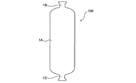
- FIG. 1 is a view showing a container according to the present invention.
- the container 100 is formed on a cylindrical body 1A having a preset outer diameter and inner diameter, a container upper part (base attachment part) 1B formed on the upper side of the body 1A, and a lower side of the body 1A. And a container bottom portion (cap attaching portion) 1C.
- the body 1A, the container top 1B, and the container bottom 1C are integrally formed.
- release of the content are attached to the container upper part 1B, and a sealing member etc. (not shown) are attached to the container bottom part 1C. .
- the material for the container examples include metals and the like, and are preferably difficult-to-work metals such as iron, titanium, and 7000 series aluminum alloys.
- the 7000 series aluminum alloys can be used to reduce the weight of the container. It is particularly preferred that
- Such a container upper portion 1B has a cylindrical workpiece W having a preset outer diameter and inner diameter, and one opening end portion of the cylindrical workpiece W is formed by a molding roller 11 of the spinning processing apparatus 1 or the like. It is obtained by processing so as to have a diameter smaller than 1A (mouth-spinning spinning). That is, as shown by the dotted line in FIG. 2, it is obtained by reducing the diameter of the processed part of the workpiece W by a predetermined angle ⁇ . The same applies to the container bottom 1C.
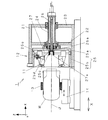
- FIG. 3 is a plan view showing the spinning apparatus 1 according to the present invention
- FIG. 4 is a cross-sectional view taken along line AA shown in FIG.
- One direction horizontal to the ground is defined as an X direction
- a direction horizontal to the ground and perpendicular to the X direction is defined as a Y direction
- a direction perpendicular to the X direction and the Y direction is defined as a Z direction.
- the spinning apparatus 1 includes a forming roller driving device 12 having two forming rollers 11, a holding device 10 having a clamping device (spinning chuck) 13 and an X-axis driving mechanism 14, an initial heating mechanism 61, and an intermediate heating mechanism 62. And a heating mechanism 60 having an induction heater power source 63 and a heating coil moving carriage 64 (heating mechanism transport mechanism), and a non-contact type radiation thermometer 70 for detecting the temperature of the processing part of the workpiece W during the processing step.
- FIG. 5 is a front view showing the forming roller driving device 12, and FIG. 6 is a cross-sectional view taken along line BB shown in FIG.
- the forming roller driving device 12 is provided with support plates 22, 23 arranged in parallel at a distance on the right side portion of the frame 21, and a rotating shaft is provided by a bearing attached to the center of these support plates 22, 23. 24 is supported so as to coincide with the axis J (X direction).
- a rotating drum 25 is fixed to the left end of the rotating shaft 24.
- a motor (not shown) is connected to the right end of the rotating shaft 24, and the rotating drum 25 is driven to rotate about the axis J as a rotating shaft.
- the inside of the rotating shaft 24 is hollow, and the forming roller adjusting shaft 26 is inserted so as to be coaxial with the rotating shaft 24 (axis line J).
- a bevel gear 26 a is fixed to the left end of the forming roller adjustment shaft 26.
- the rotary drum 25 includes a disc portion 25a and a cylindrical side wall 25b.
- a support body 25d having a through hole 25c is fixed near the center of the disk portion 25a.
- a through hole 25e is formed in the cylindrical side wall 25b.
- the end of each ball screw 27 is pivotally supported by the through holes 25c and 25e, so that the two ball screws 27 are arranged in the radial direction from the rotation shaft 24 side (rotation center).
- a bevel gear 27a is fixed to the end of each ball screw 27 on the rotating shaft 24 side, and is screwed with the bevel gear 26a of the forming roller adjusting shaft 26.
- Each ball screw 27 is screwed with a housing 11 a that supports the forming roller 11.
- the clamp device 13 holds the outer peripheral surface of the body 1A of the cylindrical workpiece W so that the axis J of the workpiece W is in the X direction.
- the X-axis drive mechanism 14 is capable of moving the clamping device 13 forward or backward in the direction of the axis J of the workpiece W (X direction or -X direction). Is pressed against the two molding rollers 11 or inserted into the heating coils 61b and 62b.
- FIG. 7A is a front view showing the initial heating mechanism 61
- FIG. 7B is a cross-sectional view taken along the line CC shown in FIG. 7A.
- the initial heating mechanism 61 includes a casing 61a, a heating coil (heating unit) 61b electrically connected to the induction heater power source 63, and a thermocouple for detecting the temperature of the processing part of the workpiece W during the heating process ( A contact type temperature sensor) 61c and a spring mechanism 61d.
- the housing 61a is a cylindrical block body having a square cylindrical outer peripheral surface and a cylindrical inner peripheral surface.
- a cylindrical heating coil 61b is fixed to the cylindrical inner peripheral surface.
- the heating coil 61b has a straight shape corresponding to the initial shape (cylindrical shape) of the processed portion of the workpiece W.
- the thermocouple 61c is installed so as to penetrate the inner peripheral surface from the outer peripheral surface of the casing 61a, and contacts the outer peripheral surface of the processing part of the workpiece W inserted into the heating coil 61b by a spring mechanism 61d. It can be made to.
- Such an initial heating mechanism 61 includes a heating position (initial heating state) A for heating the machining part of the workpiece W, and an initial heating mechanism retracting position (molding state) B for not heating the machining part of the workpiece W.
- the casing 61a is gripped by the heating coil moving carriage 64 (heating mechanism transport mechanism) so that the casing 61a can move.
- FIG. 8A is a front view showing the intermediate heating mechanism 62
- FIG. 8B is a cross-sectional view taken along the line DD shown in FIG. 8A.
- the intermediate heating mechanism 62 includes a casing 62a, heating coils (heating units) 61b and 62b that are electrically connected to the induction heater power supply 63, and a thermoelectric for detecting the temperature of the processing site of the workpiece W during the heating process. It has a pair (contact temperature sensor) 62c and a spring mechanism 62d.
- the housing 62a is a cylindrical block body having a square cylindrical outer peripheral surface, a cylindrical inner peripheral surface, and a frustoconical inner peripheral surface.
- a cylindrical heating coil 61b is fixed to the cylindrical inner peripheral surface, and a frustoconical heating coil 62b is fixed to the frustoconical inner peripheral surface. That is, the heating coil 62b has a tapered shape (a shape in which the diameter becomes smaller at the predetermined angle ⁇ ) corresponding to the deformed intermediate shape (conical truncated cone shape) of the processed portion of the workpiece W. Further, the thermocouple 62c is installed so as to penetrate the frustoconical inner peripheral surface from the outer peripheral surface of the housing 62a, and a spring mechanism is provided on the outer peripheral surface of the processing portion of the workpiece W inserted into the heating coil 62b. Etc. 62d can be brought into contact with each other.
- Such an intermediate heating mechanism 62 includes a heating position (intermediate heating state) A for heating the machining part of the workpiece W, and an intermediate heating mechanism retracting position (molding state) C for not heating the machining part of the workpiece W.
- the casing 62a is gripped by the heating coil moving carriage 64 so as to be movable.
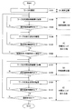
- FIG. 9 is a flowchart for explaining an example of the spinning method.
- the spinning method (ITM system) includes a holding step (A) for holding the workpiece W, an initial heating step (B) for heating the processing portion of the workpiece W by the initial heating mechanism 61, and a processing portion for the workpiece W.
- ITM system includes a holding step (A) for holding the workpiece W, an initial heating step (B) for heating the processing portion of the workpiece W by the initial heating mechanism 61, and a processing portion for the workpiece W.
- step S101 the outer peripheral surface of the body 1A of the workpiece W is fixed by the clamp device 13.
- step S102 the workpiece W is placed at the preparation position, and the initial heating mechanism 61 is moved to the heating position A, thereby bringing the initial heating state.
- the workpiece W is moved forward in the X direction by the X-axis drive mechanism 14 to place the machining portion of the workpiece W at a predetermined position in the heating coil 61b, and an alternating current having a predetermined frequency is supplied to the heating coil 61b.
- the thermocouple 61c detects the temperature of the processed part of the workpiece W.
- the heating is stopped and the process proceeds to (C) the initial spinning process.
- the above set temperature range is (solidus temperature ⁇ 250 ° C.) or more (solidus temperature ⁇ 10 ° C.) or less to obtain a container having a good shape without wrinkles even if the temperature fluctuation increases. Is more preferably (solidus temperature ⁇ 100 ° C.) or higher and (solidus temperature ⁇ 50 ° C.) or lower (see FIG. 10).
- step S104 After the workpiece W is moved backward in the ⁇ X direction by the X-axis drive mechanism 14 to place the workpiece W in the preparation position, the initial heating mechanism 61 is moved to the initial heating mechanism. By moving to the retreat position B, a molding state (a state in which the initial heating mechanism 61 and an intermediate heating mechanism 62 described later are retracted) is obtained. Next, the position of the forming roller 11 in the radial direction is adjusted by the forming roller adjusting shaft 26, and the rotating shaft 24 is driven to turn the forming roller 11.
- the workpiece W is moved forward in the X direction by the X-axis drive mechanism 14 to bring the outer peripheral surface of the processed portion of the workpiece W into contact with the forming roller 11 that is turning. Thereby, the processing part of the workpiece W is reduced in diameter.
- step S105 at the end of one pass, the temperature of the processed part of the workpiece W is detected by the non-contact type radiation thermometer 70, and it is determined whether or not it is within the set temperature range.
- step S106 it is determined whether or not the machining part of the workpiece W is still similar to the initial shape (cylindrical shape), and the machining part of the workpiece W is similar to the initial shape (cylindrical shape).
- it returns to (B) initial heating process (process of step S102), and on the other hand, when it is not similar to the initial shape (cylindrical shape), it progresses to (D) intermediate heating process.
- step S107 the workpiece W is moved backward in the -X direction by the X-axis drive mechanism 14 to place the workpiece W in the preparation position, and then the intermediate heating mechanism 62 is moved to the heating position A. By moving it, it is brought into an intermediate heating state.
- the workpiece W is advanced in the X direction by the X-axis drive mechanism 14 and arranged so that the distances (clearances) between the positions of the processing parts of the workpiece W and the heating coils 61b and 62b are constant, An alternating current having a predetermined frequency is supplied to the heating coils 61b and 62b.
- step S108 the thermocouple 62c detects the temperature of the processed part of the workpiece W. When the temperature is within the set temperature range, the heating is stopped and the process proceeds to (E) intermediate spinning process.
- step S109 the workpiece W is moved backward in the -X direction by the X-axis drive mechanism 14 to place the workpiece W in the preparation position, and then the intermediate heating mechanism 62 is moved to the intermediate heating mechanism.
- the retreat position C a molding state (a state in which the initial heating mechanism 61 and the intermediate heating mechanism 62 are retracted) is obtained.
- the position of the forming roller 11 in the radial direction is adjusted by the forming roller adjusting shaft 26, and the rotating shaft 24 is driven to turn the forming roller 11.
- the workpiece W is moved forward in the X direction by the X-axis drive mechanism 14 to bring the outer peripheral surface of the processed portion of the workpiece W into contact with the forming roller 11 that is turning. Thereby, the diameter of the processing part of the workpiece W is further reduced.
- step S110 at the end of one pass, the temperature of the processing part of the workpiece W is detected by the non-contact type radiation thermometer 70, and it is determined whether or not it is within the set temperature range.
- step S111 it is determined whether or not the processing part of the workpiece W has a final shape.
- the flowchart is terminated.
- the process returns to (D) the intermediate heating process (the process of step S107).
- the processing part of the workpiece W can always be heated uniformly within the set temperature range. Thereby, the wall thickness, tensile strength, and fatigue strength of a processed product can be made uniform.
- the intermediate heating mechanism 62 has a configuration having the frustoconical heating coil 62 b, but the burner disposed so as to correspond to the deformed intermediate shape of the processing portion of the workpiece W A configuration that is a group may be used.
- the heating mechanism 60 has the configuration including the initial heating mechanism 61 and the intermediate heating mechanism 62, but it corresponds to both the initial shape and the deformed intermediate shape of the processing portion of the workpiece W. It is good also as a structure provided only with the heating mechanism which has a frustoconical heating coil of the possible predetermined angle ((theta) / 2).
- the heating mechanism 60 has a configuration including the initial heating mechanism 61 and the intermediate heating mechanism 62, but the cylindrical heating coil 61b in FIG. The workpiece W may be inserted and heated up to 61b during heating, and the workpiece W may be inserted and heated up to the tapered heating coil 62b during intermediate heating.
- the present invention can be suitably used for a spinning processing apparatus for manufacturing a container for filling with hydrogen gas or the like.
Landscapes
- Engineering & Computer Science (AREA)
- Mechanical Engineering (AREA)
- Shaping Metal By Deep-Drawing, Or The Like (AREA)
Abstract
[Problème] Fournir un dispositif de repoussage pouvant rendre uniforme l'épaisseur de paroi, la résistance à la traction et la résistance à la fatigue d'un article usiné. [Solution] La présente invention concerne un dispositif de repoussage 1 qui amène progressivement une partie usinée d'une pièce de fabrication cylindrique W à se contracter diamétralement qui est pourvu d'un mécanisme de maintien 10 pour maintenir la pièce de fabrication W, un mécanisme de chauffage 60 pour chauffer la partie usinée de la pièce de fabrication W, et un rouleau de formage 11 qui est pressé contre la partie usinée de la pièce de fabrication W, le mécanisme de chauffage 60 ayant une configuration dans laquelle une unité de chauffage 62b est formée de façon à correspondre à une forme intermédiaire déformée de la partie usinée de la pièce de fabrication W.
Applications Claiming Priority (4)
| Application Number | Priority Date | Filing Date | Title |
|---|---|---|---|
| JP2016-204236 | 2016-10-18 | ||
| JP2016-204237 | 2016-10-18 | ||
| JP2016204236A JP6722946B2 (ja) | 2016-10-18 | 2016-10-18 | スピニング加工装置 |
| JP2016204237A JP6736086B2 (ja) | 2016-10-18 | 2016-10-18 | スピニング加工方法及びそれを用いて製造された容器 |
Publications (1)
| Publication Number | Publication Date |
|---|---|
| WO2018074152A1 true WO2018074152A1 (fr) | 2018-04-26 |
Family
ID=62018543
Family Applications (1)
| Application Number | Title | Priority Date | Filing Date |
|---|---|---|---|
| PCT/JP2017/034607 Ceased WO2018074152A1 (fr) | 2016-10-18 | 2017-09-26 | Dispositif et procédé de repoussage |
Country Status (1)
| Country | Link |
|---|---|
| WO (1) | WO2018074152A1 (fr) |
Cited By (1)
| Publication number | Priority date | Publication date | Assignee | Title |
|---|---|---|---|---|
| CN115318924A (zh) * | 2022-10-17 | 2022-11-11 | 四川大学 | 一种钛合金无缝气瓶旋压设备及其旋压成型方法 |
Citations (3)
| Publication number | Priority date | Publication date | Assignee | Title |
|---|---|---|---|---|
| JPH02118630U (fr) * | 1989-03-02 | 1990-09-25 | ||
| US20100000279A1 (en) * | 2005-05-30 | 2010-01-07 | Mt Aerospace Ag | Method and device for forming an essentially flat metal blank to produce a thin-walled, shell-type body, and the use of same |
| WO2010073476A1 (fr) * | 2008-12-23 | 2010-07-01 | 株式会社 ディムコ | Très long tube métallique à paroi mince, procédé de fabrication d'un très long tube métallique à paroi mince et dispositif utilisant un très long tube métallique à paroi mince en tant que rouleau ou courroie |
-
2017
- 2017-09-26 WO PCT/JP2017/034607 patent/WO2018074152A1/fr not_active Ceased
Patent Citations (3)
| Publication number | Priority date | Publication date | Assignee | Title |
|---|---|---|---|---|
| JPH02118630U (fr) * | 1989-03-02 | 1990-09-25 | ||
| US20100000279A1 (en) * | 2005-05-30 | 2010-01-07 | Mt Aerospace Ag | Method and device for forming an essentially flat metal blank to produce a thin-walled, shell-type body, and the use of same |
| WO2010073476A1 (fr) * | 2008-12-23 | 2010-07-01 | 株式会社 ディムコ | Très long tube métallique à paroi mince, procédé de fabrication d'un très long tube métallique à paroi mince et dispositif utilisant un très long tube métallique à paroi mince en tant que rouleau ou courroie |
Cited By (1)
| Publication number | Priority date | Publication date | Assignee | Title |
|---|---|---|---|---|
| CN115318924A (zh) * | 2022-10-17 | 2022-11-11 | 四川大学 | 一种钛合金无缝气瓶旋压设备及其旋压成型方法 |
Similar Documents
| Publication | Publication Date | Title |
|---|---|---|
| KR101508108B1 (ko) | 스피닝 성형 장치 및 성형 방법 | |
| JP6574518B2 (ja) | 管の拡径方法および成形装置 | |
| CN109108139A (zh) | 一种基于复合加热的钛基合金材料旋压成形方法 | |
| CN104785929A (zh) | 管状零件光纤激光对焊夹紧装置 | |
| JP2018103221A (ja) | スピニングマシンの材料加工方法 | |
| JP6722946B2 (ja) | スピニング加工装置 | |
| CN112756460B (zh) | 一种超导腔制造方法 | |
| JP2005298326A (ja) | 調整された円形又は輪郭を有するガラス管の連続的に製造する方法と装置 | |
| TWI503220B (zh) | Method for manufacturing resin bottles | |
| US10632522B2 (en) | Method of manufacturing preliminary formed body and axisymmetrical component | |
| WO2018074152A1 (fr) | Dispositif et procédé de repoussage | |
| CN103920985B (zh) | 一种薄壁管类零件轴向摩擦焊的快速预热装置 | |
| CN110369573B (zh) | 一种大口径钢管弯管成型方法及装置 | |
| JP5923173B2 (ja) | スピニング成形方法及びスピニング成形装置 | |
| JP6736086B2 (ja) | スピニング加工方法及びそれを用いて製造された容器 | |
| US20130219981A1 (en) | Method for shaping an essentially flat-surfaced blank to form a shell body and use thereof | |
| US6997016B2 (en) | Method and apparatus for manufacturing glass tube | |
| KR101295315B1 (ko) | 이중관형 엘보의 성형방법 | |
| CN104438495A (zh) | 一步法热煨弯管装置及工艺 | |
| CN105934293B (zh) | 轧制工具和用于制造涡轮机盘的方法 | |
| CN114871705B (zh) | 一种自稳定高精度导电薄壁圆环制备方法及其加工夹具 | |
| CN105414261B (zh) | 自动校圆机 | |
| Wilson et al. | Non-axisymmetric tube spinning by offset rotation | |
| CN112548126A (zh) | 车床 | |
| RU2521938C1 (ru) | Способ изготовления тонкостенных труб с наружными спиральными ребрами и устройство для его осуществления |
Legal Events
| Date | Code | Title | Description |
|---|---|---|---|
| 121 | Ep: the epo has been informed by wipo that ep was designated in this application |
Ref document number: 17861321 Country of ref document: EP Kind code of ref document: A1 |
|
| NENP | Non-entry into the national phase |
Ref country code: DE |
|
| 122 | Ep: pct application non-entry in european phase |
Ref document number: 17861321 Country of ref document: EP Kind code of ref document: A1 |