WO2018077048A1 - Procédé de commande d'optimisation d'intervalle de fonctionnement d'éjecteur - Google Patents
Procédé de commande d'optimisation d'intervalle de fonctionnement d'éjecteur Download PDFInfo
- Publication number
- WO2018077048A1 WO2018077048A1 PCT/CN2017/106079 CN2017106079W WO2018077048A1 WO 2018077048 A1 WO2018077048 A1 WO 2018077048A1 CN 2017106079 W CN2017106079 W CN 2017106079W WO 2018077048 A1 WO2018077048 A1 WO 2018077048A1
- Authority
- WO
- WIPO (PCT)
- Prior art keywords
- injector
- value
- pressure
- primary flow
- proportional coefficient
- Prior art date
- Legal status (The legal status is an assumption and is not a legal conclusion. Google has not performed a legal analysis and makes no representation as to the accuracy of the status listed.)
- Ceased
Links
Images
Classifications
-
- F—MECHANICAL ENGINEERING; LIGHTING; HEATING; WEAPONS; BLASTING
- F25—REFRIGERATION OR COOLING; COMBINED HEATING AND REFRIGERATION SYSTEMS; HEAT PUMP SYSTEMS; MANUFACTURE OR STORAGE OF ICE; LIQUEFACTION SOLIDIFICATION OF GASES
- F25B—REFRIGERATION MACHINES, PLANTS OR SYSTEMS; COMBINED HEATING AND REFRIGERATION SYSTEMS; HEAT PUMP SYSTEMS
- F25B9/00—Compression machines, plants or systems, in which the refrigerant is air or other gas of low boiling point
- F25B9/08—Compression machines, plants or systems, in which the refrigerant is air or other gas of low boiling point using ejectors
-
- F—MECHANICAL ENGINEERING; LIGHTING; HEATING; WEAPONS; BLASTING
- F25—REFRIGERATION OR COOLING; COMBINED HEATING AND REFRIGERATION SYSTEMS; HEAT PUMP SYSTEMS; MANUFACTURE OR STORAGE OF ICE; LIQUEFACTION SOLIDIFICATION OF GASES
- F25B—REFRIGERATION MACHINES, PLANTS OR SYSTEMS; COMBINED HEATING AND REFRIGERATION SYSTEMS; HEAT PUMP SYSTEMS
- F25B49/00—Arrangement or mounting of control or safety devices
- F25B49/02—Arrangement or mounting of control or safety devices for compression type machines, plants or systems
Definitions
- the invention relates to the technical field of refrigeration, and in particular relates to an optimized control method for an operating range of an injector.
- the injector replaces the compressor in a conventional refrigeration system and is a key component in a jet refrigeration system.
- An ejector is a device that mixes two different pressure fluids with each other and exchanges energy to form a mixed fluid at a center pressure. It does not directly consume mechanical work or electrical energy to improve parameters such as fluid pressure and temperature. It has a simple structure, low cost, no moving parts, and is suitable for use in any flow pattern including two-phase flow. Ejectors have long been used in low-grade heat source-driven refrigeration systems and are a good source of energy recovery for waste heat.
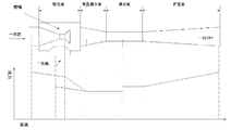
- the injector usually consists of a main nozzle, a receiving chamber, a mixing chamber and a diffusing chamber.
- the static pressure energy and thermal energy of the gas flow are converted into kinetic energy to form a low pressure at the nozzle outlet to generate a suction effect on the ejector fluid, and due to the turbulent diffusion of the jet boundary layer,
- the energy is exchanged with the surrounding entrained ejector fluid to form a pressure-centered mixed fluid.
- the speed equalization of the working fluid and the ejector fluid after entering the mixing chamber is usually accompanied by an increase in pressure. Subsequently, the fluid enters the diffuser chamber, the speed is continuously slowed down, and the kinetic energy is continuously converted into static pressure energy.
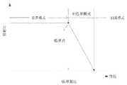
- the injector When the back pressure of the injector is different, the injector is in three different operating modes, namely critical mode, subcritical mode, and reflow mode. As shown in FIG. 2, when the back pressure is small, the injection coefficient of the injector always maintains a constant value as the back pressure increases, and the injection coefficient is the maximum value at this time. When the back pressure increases to the critical point, the back pressure continues to increase, and the injection coefficient decreases rapidly until it decreases to zero. This process is a subcritical mode. The back pressure continues to increase and reflow occurs, at which point the injector operates in reflow mode. Among them, the critical back pressure is the critical value of the transition between the critical mode and the subcritical mode, which is the critical operating point of the injector.
- the mode of operation of the injector is greatly affected by the primary flow pressure.
- the object of the present invention is to solve the above problems, and an optimized control method for an operating range of an injector is proposed, which enables the injector to operate in an optimal working range, thereby ensuring stable operation of the system.
- An optimized control method for an injector operating interval includes the following steps:
- the relationship between the primary flow pressure of the injector and the critical back pressure is approximately proportional to a linear relationship, wherein the ratio
- the coefficient is K
- the unknown constant is B
- the K value and the B value are determined by least squares method
- the proportional coefficient K s is a set multiple of the proportional coefficient K*, and the working interval of the injector is divided into three parts according to the proportional coefficient K* and the proportional coefficient K s ;
- the working state of the injector is determined, and the injector is operated in a stable operating state by adjusting the generated pressure value.
- step (1) is:
- the correlation R 2 is used to evaluate the accuracy of the calculated P g value.
- step 2) is:
- the calculation method of the correlation R 2 is:
- the proportional coefficient K* at the critical point of the injector is specifically:
- P g is the primary flow pressure value when the injector performance is optimal.
- K* is the proportional coefficient at the critical point of the injector, and ⁇ is a positive number.
- the method of the invention enables the injector to operate in an optimal working range, which is beneficial to improving the energy efficiency and stability of the system.
- Figure 1 is a diagram of the composition of the injector and its working pressure diagram
- Figure 2 is a schematic diagram of three different modes of operation of the injector
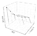
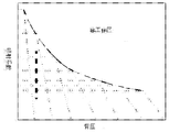
- Figure 3 (b) is a schematic diagram showing the relationship between primary flow pressure and back pressure
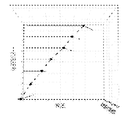
- Figure 3 (c) is a schematic diagram showing the connection of critical back pressure values under different working conditions
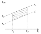
- Figure 4 is a schematic view of the working section of the injector.
- An optimized control method for an injector operating interval includes the following steps:
- the relationship between the primary flow pressure of the injector and the critical back pressure is approximately proportional to a linear relationship, wherein the proportional coefficient is K, the unknown constant is B, and the K value and the B value are determined by least squares method;
- the proportional coefficient K s is a set multiple of the proportional coefficient K*, and the working interval of the injector is divided into three parts according to the proportional coefficient K* and the proportional coefficient K s ;
- the working state of the injector is determined, and the injector is operated in a stable operating state by adjusting the generated pressure value.
- Fig. 3(a) The three-dimensional relationship between the available injection coefficient, primary flow pressure and back pressure is shown in Fig. 3(a).
- Fig. 3(b) can be clearly seen from Fig. 3(b).
- the primary flow pressure is approximately proportional to the back pressure.
- Fig. 3(c) the critical back pressure values under different operating conditions are connected.
- the injector structure is fixed, the increase of the primary flow pressure leads to a decrease in the injection coefficient and an increase in the critical back pressure.
- y i is the actual value
- f(x i ) is the function value calculated by x; the closer R 2 is to 1, the higher the correlation, the higher the accuracy.
- an operating range is defined, in which the injector can operate efficiently and stably, that is, the optimal interval, and the injector operating interval is controlled within this range. Significance.
- the following provides an optimal operation interval control method for the injector.
- K* the slope at the critical point of the injector
- P g the primary flow pressure value when the injector performance is optimal.
- ⁇ is a positive number, for example 0.1.
- the injector operating range can be divided into three parts by K*, K s , as shown in Figure 4.
- the injector is operated in the optimal interval, the shaded part in Fig. 4, in Fig. 4, the primary flow pressure value when P gL is in the critical working state (that is, when K is K*), P gH is the primary flow pressure value when K is K s , and P cL and P cH are determined according to the actual working state.
- the injector system can operate stably and stably.
Landscapes
- Engineering & Computer Science (AREA)
- Physics & Mathematics (AREA)
- Mechanical Engineering (AREA)
- Thermal Sciences (AREA)
- General Engineering & Computer Science (AREA)
- Jet Pumps And Other Pumps (AREA)
Abstract
L'invention concerne un procédé de commande d'optimisation d'intervalle de fonctionnement d'un éjecteur qui comprend les étapes suivantes consistant à : approximer la relation entre une pression d'écoulement primaire d'un éjecteur et une contre-pression critique vers une relation linéaire directement proportionnelle, et déterminer un coefficient de proportionnalité K* au niveau d'un point critique de l'éjecteur conformément à une valeur de pression d'écoulement primaire optimale; diviser un intervalle de travail de l'éjecteur en trois parties conformément au coefficient de proportionnalité K* et à un coefficient de proportionnalité Ks; déterminer un état de travail de l'éjecteur conformément à l'intervalle de travail au lequel se trouve le coefficient de proportionnalité K de l'éjecteur pendant un travail pratique, et permettre à l'éjecteur de travailler à un état de fonctionnement stable au moyen d'un réglage d'une valeur d'apparition de pression.
Applications Claiming Priority (2)
| Application Number | Priority Date | Filing Date | Title |
|---|---|---|---|
| CN201610970116.7 | 2016-10-27 | ||
| CN201610970116.7A CN106500383B (zh) | 2016-10-27 | 2016-10-27 | 一种喷射器运行区间的优化控制方法 |
Publications (1)
| Publication Number | Publication Date |
|---|---|
| WO2018077048A1 true WO2018077048A1 (fr) | 2018-05-03 |
Family
ID=58322027
Family Applications (1)
| Application Number | Title | Priority Date | Filing Date |
|---|---|---|---|
| PCT/CN2017/106079 Ceased WO2018077048A1 (fr) | 2016-10-27 | 2017-10-13 | Procédé de commande d'optimisation d'intervalle de fonctionnement d'éjecteur |
Country Status (2)
| Country | Link |
|---|---|
| CN (1) | CN106500383B (fr) |
| WO (1) | WO2018077048A1 (fr) |
Cited By (1)
| Publication number | Priority date | Publication date | Assignee | Title |
|---|---|---|---|---|
| CN113553675A (zh) * | 2021-07-29 | 2021-10-26 | 上海电力大学 | 一种喷射器优化方法及装置 |
Families Citing this family (4)
| Publication number | Priority date | Publication date | Assignee | Title |
|---|---|---|---|---|
| CN106529712B (zh) * | 2016-10-27 | 2019-03-22 | 山东大学 | 一种喷射器临界工作点引射比预测优化方法 |
| CN106500383B (zh) * | 2016-10-27 | 2019-07-05 | 山东大学 | 一种喷射器运行区间的优化控制方法 |
| CN111857192B (zh) * | 2019-04-29 | 2024-03-05 | 新奥数能科技有限公司 | 喷射器的调控方法及装置 |
| CN115569754B (zh) * | 2022-09-27 | 2024-10-25 | 山东大学 | 一种可调喷射器变工况运行的控制方法和系统 |
Citations (8)
| Publication number | Priority date | Publication date | Assignee | Title |
|---|---|---|---|---|
| EP1134517A2 (fr) * | 2000-03-15 | 2001-09-19 | Denso Corporation | Système à cycle d'éjection avec pression critique du fluide frigorigène |
| CN101532513A (zh) * | 2008-03-12 | 2009-09-16 | 株式会社电装 | 喷射器 |
| CN102142048A (zh) * | 2011-01-25 | 2011-08-03 | 西安交通大学 | 一种用于引射器的通用优化设计方法 |
| JP4812665B2 (ja) * | 2007-03-16 | 2011-11-09 | 三菱電機株式会社 | エジェクタ及び冷凍サイクル装置 |
| CN103148649A (zh) * | 2013-03-27 | 2013-06-12 | 上海理工大学 | 蒸汽压缩制冷循环系统中喷射器设计方法 |
| EP2754978A1 (fr) * | 2013-01-15 | 2014-07-16 | Epta S.p.A. | Installation frigorifique avec éjecteur |
| CN104504252A (zh) * | 2014-12-10 | 2015-04-08 | 广西大学 | 一种跨临界co2制冷循环中喷射器的扩压室效率的评价方法 |
| CN106500383A (zh) * | 2016-10-27 | 2017-03-15 | 山东大学 | 一种喷射器运行区间的优化控制方法 |
Family Cites Families (1)
| Publication number | Priority date | Publication date | Assignee | Title |
|---|---|---|---|---|
| CN104406327A (zh) * | 2014-12-16 | 2015-03-11 | 山东大学 | 多模废热驱动汽车空调系统 |
-
2016
- 2016-10-27 CN CN201610970116.7A patent/CN106500383B/zh active Active
-
2017
- 2017-10-13 WO PCT/CN2017/106079 patent/WO2018077048A1/fr not_active Ceased
Patent Citations (9)
| Publication number | Priority date | Publication date | Assignee | Title |
|---|---|---|---|---|
| EP1134517A2 (fr) * | 2000-03-15 | 2001-09-19 | Denso Corporation | Système à cycle d'éjection avec pression critique du fluide frigorigène |
| CN1316636A (zh) * | 2000-03-15 | 2001-10-10 | 株式会社电装 | 具有临界致冷剂压力的排出管循环系统 |
| JP4812665B2 (ja) * | 2007-03-16 | 2011-11-09 | 三菱電機株式会社 | エジェクタ及び冷凍サイクル装置 |
| CN101532513A (zh) * | 2008-03-12 | 2009-09-16 | 株式会社电装 | 喷射器 |
| CN102142048A (zh) * | 2011-01-25 | 2011-08-03 | 西安交通大学 | 一种用于引射器的通用优化设计方法 |
| EP2754978A1 (fr) * | 2013-01-15 | 2014-07-16 | Epta S.p.A. | Installation frigorifique avec éjecteur |
| CN103148649A (zh) * | 2013-03-27 | 2013-06-12 | 上海理工大学 | 蒸汽压缩制冷循环系统中喷射器设计方法 |
| CN104504252A (zh) * | 2014-12-10 | 2015-04-08 | 广西大学 | 一种跨临界co2制冷循环中喷射器的扩压室效率的评价方法 |
| CN106500383A (zh) * | 2016-10-27 | 2017-03-15 | 山东大学 | 一种喷射器运行区间的优化控制方法 |
Cited By (2)
| Publication number | Priority date | Publication date | Assignee | Title |
|---|---|---|---|---|
| CN113553675A (zh) * | 2021-07-29 | 2021-10-26 | 上海电力大学 | 一种喷射器优化方法及装置 |
| CN113553675B (zh) * | 2021-07-29 | 2022-12-13 | 上海电力大学 | 一种喷射器优化方法及装置 |
Also Published As
| Publication number | Publication date |
|---|---|
| CN106500383A (zh) | 2017-03-15 |
| CN106500383B (zh) | 2019-07-05 |
Similar Documents
| Publication | Publication Date | Title |
|---|---|---|
| WO2018077048A1 (fr) | Procédé de commande d'optimisation d'intervalle de fonctionnement d'éjecteur | |
| Diez et al. | Contact line instabilities of thin liquid films | |
| CN106337680A (zh) | 一种油藏生产井可采储量的确定方法 | |
| CN103968629B (zh) | 降膜式冷水机组及其调节方法 | |
| CN111561301A (zh) | 一种确定稠油油藏注水开发的原油黏度界限方法 | |
| CN101727023A (zh) | 蚀刻液浓度控制方法 | |
| WO2018077047A1 (fr) | Procédé d'optimisation de prédiction de rapport d'entraînement de point de fonctionnement critique d'éjecteur | |
| Amaral et al. | On the influence of viscosity on ESP performance | |
| Tang et al. | Study on evolution laws of two-phase choking flow and entrainment performance of steam ejector oriented towards MED-TVC desalination system | |
| JP5877532B2 (ja) | プロセシングシステムの自己同調装置および自己同調方法 | |
| CN108287571A (zh) | 一种流量控制系统泵运行区间判断方法 | |
| Yang et al. | Leakage vortices and energy characteristics of semi-open sewage pump with various blade tip alterations | |
| CN112627904B (zh) | 一种新型铲斗型气膜冷却孔及其设计方法 | |
| CN108087259A (zh) | 一种变频循环水泵功耗的计算方法 | |
| CN118673828A (zh) | 一种用于工程计算的超燃冲压发动机湍流模拟方法 | |
| CN113553675B (zh) | 一种喷射器优化方法及装置 | |
| CN106640004B (zh) | 注汽锅炉出口的蒸汽热力参数的计算方法及其装置 | |
| CN206468425U (zh) | 发动机及其电控水泵 | |
| CN108268060B (zh) | 一种流量控制方法 | |
| CN108415468A (zh) | 一种流量控制系统及优化控制方法 | |
| CN207781540U (zh) | 一种单片湿法蚀刻工艺的蚀刻液输送装置 | |
| Seki et al. | DNS of turbulent heat transfer in a channel flow with different thermal boundary conditions | |
| Terekhov et al. | Effect of boundary layer thickness before the flow separation on aerodynamic characteristics and heat transfer behind an abrupt expansion in a round tube | |
| CN116223046A (zh) | 一种超临界介质计量方法及调节装置 | |
| Van Der Lingen | A jet pump design theory |
Legal Events
| Date | Code | Title | Description |
|---|---|---|---|
| 121 | Ep: the epo has been informed by wipo that ep was designated in this application |
Ref document number: 17864859 Country of ref document: EP Kind code of ref document: A1 |
|
| NENP | Non-entry into the national phase |
Ref country code: DE |
|
| 32PN | Ep: public notification in the ep bulletin as address of the adressee cannot be established |
Free format text: NOTING OF LOSS OF RIGHTS PURSUANT TO RULE 112(1) EPC (EPO FORM 1205A DATED 08/10/2019) |
|
| 122 | Ep: pct application non-entry in european phase |
Ref document number: 17864859 Country of ref document: EP Kind code of ref document: A1 |