WO2018078853A1 - 劣化診断装置および空気調和機 - Google Patents
劣化診断装置および空気調和機 Download PDFInfo
- Publication number
- WO2018078853A1 WO2018078853A1 PCT/JP2016/082261 JP2016082261W WO2018078853A1 WO 2018078853 A1 WO2018078853 A1 WO 2018078853A1 JP 2016082261 W JP2016082261 W JP 2016082261W WO 2018078853 A1 WO2018078853 A1 WO 2018078853A1
- Authority
- WO
- WIPO (PCT)
- Prior art keywords
- compressor
- vibration
- deterioration
- vibration detection
- compression mechanism
- Prior art date
- Legal status (The legal status is an assumption and is not a legal conclusion. Google has not performed a legal analysis and makes no representation as to the accuracy of the status listed.)
- Ceased
Links
Images


Classifications
-
- F—MECHANICAL ENGINEERING; LIGHTING; HEATING; WEAPONS; BLASTING
- F04—POSITIVE - DISPLACEMENT MACHINES FOR LIQUIDS; PUMPS FOR LIQUIDS OR ELASTIC FLUIDS
- F04B—POSITIVE-DISPLACEMENT MACHINES FOR LIQUIDS; PUMPS
- F04B49/00—Control, e.g. of pump delivery, or pump pressure of, or safety measures for, machines, pumps, or pumping installations, not otherwise provided for, or of interest apart from, groups F04B1/00 - F04B47/00
- F04B49/10—Other safety measures
-
- F—MECHANICAL ENGINEERING; LIGHTING; HEATING; WEAPONS; BLASTING
- F04—POSITIVE - DISPLACEMENT MACHINES FOR LIQUIDS; PUMPS FOR LIQUIDS OR ELASTIC FLUIDS
- F04B—POSITIVE-DISPLACEMENT MACHINES FOR LIQUIDS; PUMPS
- F04B51/00—Testing machines, pumps, or pumping installations
-
- F—MECHANICAL ENGINEERING; LIGHTING; HEATING; WEAPONS; BLASTING
- F04—POSITIVE - DISPLACEMENT MACHINES FOR LIQUIDS; PUMPS FOR LIQUIDS OR ELASTIC FLUIDS
- F04C—ROTARY-PISTON, OR OSCILLATING-PISTON, POSITIVE-DISPLACEMENT MACHINES FOR LIQUIDS; ROTARY-PISTON, OR OSCILLATING-PISTON, POSITIVE-DISPLACEMENT PUMPS
- F04C28/00—Control of, monitoring of, or safety arrangements for, pumps or pumping installations specially adapted for elastic fluids
- F04C28/28—Safety arrangements; Monitoring
-
- F—MECHANICAL ENGINEERING; LIGHTING; HEATING; WEAPONS; BLASTING
- F04—POSITIVE - DISPLACEMENT MACHINES FOR LIQUIDS; PUMPS FOR LIQUIDS OR ELASTIC FLUIDS
- F04D—NON-POSITIVE-DISPLACEMENT PUMPS
- F04D27/00—Control, e.g. regulation, of pumps, pumping installations or pumping systems specially adapted for elastic fluids
- F04D27/001—Testing thereof; Determination or simulation of flow characteristics; Stall or surge detection, e.g. condition monitoring
-
- G—PHYSICS
- G01—MEASURING; TESTING
- G01M—TESTING STATIC OR DYNAMIC BALANCE OF MACHINES OR STRUCTURES; TESTING OF STRUCTURES OR APPARATUS, NOT OTHERWISE PROVIDED FOR
- G01M7/00—Vibration-testing of structures; Shock-testing of structures
- G01M7/02—Vibration-testing by means of a shake table
-
- F—MECHANICAL ENGINEERING; LIGHTING; HEATING; WEAPONS; BLASTING
- F04—POSITIVE - DISPLACEMENT MACHINES FOR LIQUIDS; PUMPS FOR LIQUIDS OR ELASTIC FLUIDS
- F04B—POSITIVE-DISPLACEMENT MACHINES FOR LIQUIDS; PUMPS
- F04B2207/00—External parameters
- F04B2207/70—Warnings
Definitions
- the present invention relates to a deterioration diagnosis device for diagnosing deterioration of a compressor and an air conditioner.
- Patent Document 1 discloses a technique for predicting the life of a compressor based on a vibration detection value obtained by an acceleration sensor attached to a foot portion of the compressor.
- the air conditioner of Patent Document 2 has a terminal cover on the peripheral surface of the compressor shell, and when the vibration detection value by the acceleration sensor provided in the terminal cover shows an abnormality, the compressor Is configured to stop.
- the foot portion of the compressor is a position where the vibration of the compressor due to the rotational movement of the compression mechanism portion is not easily transmitted.
- the terminal cover that covers the power supply connecting portion is generally provided at a position where the vibration of the compressor is not easily transmitted.
- the terminal cover since the terminal cover has a low fixing strength, noise or the like is likely to be mixed into the vibration detection value by the acceleration sensor in the terminal cover, and there is a problem in detection accuracy.
- the techniques disclosed in Patent Documents 1 and 2 cannot accurately detect vibrations caused by the rotational motion of the compression mechanism, and therefore cannot accurately diagnose the degree of deterioration of the compressor.
- the present invention has been made in order to solve the above-described problems, and includes a deterioration diagnosis device and an air that accurately detect vibration due to rotational movement of a compression mechanism section and perform highly accurate deterioration diagnosis of a compressor.
- the purpose is to provide a harmony machine.
- a deterioration diagnosis apparatus is a deterioration diagnosis apparatus for diagnosing deterioration of a compressor having a compression mechanism portion that is driven in accordance with the rotational movement of a rotating shaft and a shell that forms an outer shell.
- the vibration detection device includes a vibration detection device fixed to the outer wall where the mechanism portion is located.
- the vibration detection device is connected to a vibration sensor that detects the vibration of the compressor, a sensor holding portion provided with the vibration sensor, and a sensor holding portion. And a plurality of protrusions that are formed on the surface opposite to the sensor holding portion of the base and that contact the outer wall.
- An air conditioner includes a compression mechanism that is driven in accordance with the rotational movement of a rotary shaft, a compressor that compresses a refrigerant, a heat source side heat exchanger that exchanges heat between the heat medium and the refrigerant, and a refrigerant
- a decompression device that adjusts the flow rate of the refrigerant, a use-side heat exchanger that exchanges heat between the indoor air and the refrigerant through a refrigerant pipe, and a refrigeration cycle in which the refrigerant circulates, and the above-described deterioration diagnosis device It is.
- the sensor holding portion including the vibration sensor is integrally formed with the plurality of protrusions that contact the outer wall where the compression mechanism portion of the shell is located. Therefore, it is possible to accurately detect deterioration of the compressor.
- FIG. 1 It is a block diagram of the air conditioner and the deterioration diagnosis apparatus according to Embodiment 1 of the present invention. It is an external view which shows the compressor and vibration detection apparatus of FIG. It is explanatory drawing which shows roughly the cross section which cut
- FIG. 10 is a schematic cross-sectional view showing a state in which the vibration detection device according to Modification 1-1 of Embodiment 1 of the present invention is cut along an xy plane.
- FIG. 10 is a schematic cross-sectional view showing a state in which the vibration detection device according to Modification 1-2 of Embodiment 1 of the present invention is cut along an xy plane. It is a flowchart which shows the operation example of the deterioration diagnostic apparatus of FIG. It is an external view which shows the compressor and vibration detection apparatus which concern on Embodiment 2 of this invention. It is the perspective view which expanded and showed the vibration detection apparatus of FIG. It is a schematic sectional drawing which shows the state which cut
- FIG. 1 is a configuration diagram of an air conditioner and a deterioration diagnosis apparatus according to Embodiment 1 of the present invention.
- the air conditioner 200 has an outdoor unit 200A arranged outdoors and an indoor unit 200B arranged indoors.
- the outdoor unit 200 ⁇ / b> A includes a compressor 100, a suction muffler 101 connected to the suction side of the compressor 100, and a four-way valve 103 connected to the discharge side of the compressor 100.
- the outdoor unit 200A includes, for example, a fin-and-tube heat exchanger, and includes a heat source side heat exchanger 104 that exchanges heat between the outside air and the refrigerant, and an electric expansion valve, for example, and a decompression device 105 that adjusts the flow rate of the refrigerant. And have.
- the indoor unit 200B includes, for example, a fin-and-tube heat exchanger, and includes a use-side heat exchanger 106 that exchanges heat between indoor air and refrigerant.
- the compressor 100 the suction muffler 101, the four-way valve 103, the heat source side heat exchanger 104, the decompression device 105, and the use side heat exchanger 106 are connected by the refrigerant pipe 150, and the refrigerant circulates. Has a refrigeration cycle.
- the compressor 100 sucks low-pressure gas refrigerant and compresses it into a high-pressure gas refrigerant.
- the compressor 100 may be capable of arbitrarily changing the operating frequency by inverter control, or may be a constant speed having no function of changing the operating frequency.
- various compressors such as a scroll compressor, a rotary compressor, a reciprocating compressor, a rotary compressor, a helical compressor, and a turbo compressor can be employed.
- the four-way valve 103 switches the refrigerant flow from the compressor 100.
- the four-way valve 103 is connected to the solid line side in FIG. 1 during the heating operation, and is connected to the broken line side in FIG. 1 during the cooling operation.
- the outdoor unit 200A has a control device 300 that controls the refrigeration cycle. That is, the control device 300 controls the operation frequency of the compressor 100, the switching process of the four-way valve 103, the opening degree of the decompression device 105, and the like. And the deterioration diagnosis apparatus 30 is provided in the outdoor unit 200A.
- the deterioration diagnosis device 30 includes a vibration detection device 10 and a diagnosis processing device 20.
- the vibration detection device 10 and the diagnostic processing device 20 are connected by wire or wirelessly. That is, the diagnostic processing device 20 is configured to acquire vibration detection values from the first vibration sensor 12a and the second vibration sensor 12b from the vibration detection device 10 by wire or wirelessly.
- the indoor unit 200B includes a display unit 400 that includes, for example, a liquid crystal display (LCD).
- LCD liquid crystal display
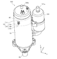
- FIG. 2 is an external view showing the compressor and vibration detection device of FIG.
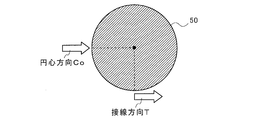
- FIG. 3 is an explanatory view schematically showing a cross section of the compression mechanism portion and the shell of FIG. 2 cut along the xy plane.
- the compressor 100 has a shell 50 and a foot 60.
- the shell 50 forms an outer shell of the compressor 100.
- the compressor 100 has a compression mechanism 40 that is driven in accordance with the rotational movement of a rotating shaft (not shown) inside the shell 50.
- the compression mechanism unit 40 is connected to an electric motor (not shown) by a rotation shaft, and the rotation shaft transmits the rotational force of the electric motor to the compression mechanism unit 40.
- the compressor 100 is provided with a discharge pipe 100a, and the suction muffler 101 is provided with a suction pipe 101a.
- the compression mechanism unit 40 vibrates due to rotational movement or reciprocation of internal movable parts, and the vibration is transmitted to the shell 50.
- the vibration of the compression mechanism 40 is transmitted more strongly to the portion of the shell 50 located on the outer periphery of the compression mechanism 40.
- the vibration pattern resulting from the motion of the movable component of the compression mechanism part 40 is transmitted to the shell 50.
- FIG. Therefore, as shown in FIG. 2, the vibration detection device 10 is fixed to the outer wall where the compression mechanism 40 of the shell 50 is located.
- the vibration detection apparatus 10 includes a sensor holding unit 12 having a first vibration sensor 12a and a second vibration sensor 12b, and a holding member 12c. That is, the sensor holding part 12 is provided with the first vibration sensor 12a and the second vibration sensor 12b on the holding member 12c.
- the vibration detection device 10 has an attachment portion 11 connected to the sensor holding portion 12. The attachment portion 11 is closer to the compressor 100 than the sensor holding portion 12 in a state where the vibration detection device 10 is fixed to the compressor 100.
- the first vibration sensor 12 a and the second vibration sensor 12 b are arranged so that the vibration detection direction coincides with the movement direction of the movable part of the compression mechanism unit 40.
- the moving direction of the movable part of the compression mechanism unit 40 includes a tangential direction T that is a tangential direction of the rotation path of the compression mechanism unit 40 and a circular center that is a direction from the outer wall of the shell 50 toward the center of the compression mechanism unit 40.
- the first vibration sensor 12a is arranged so that the vibration detection direction coincides with the tangential direction T.
- the second vibration sensor 12b is arranged so that the vibration detection direction coincides with the circular center direction Co.
- the first vibration sensor 12a detects vibration along the tangential direction T of the compressor 100 resulting from the rotational movement of the movable part of the compression mechanism 40 as the first vibration detection value.
- the 2nd vibration sensor 12b detects the vibration along the center direction Co of the compressor 100 resulting from the reciprocating motion of the movable part of the compression mechanism part 40 as a 2nd vibration detection value.
- the tangential direction T is parallel to the x-axis direction
- the circular center direction Co is parallel to the y-axis direction
- the axial direction of the rotation axis corresponds to the z-axis direction.
- the tangential direction T is a direction perpendicular to the diameter direction of the shell 50 in the xy section
- the circular center direction Co corresponds to the diameter direction of the shell 50 in the xy section.
- the first vibration sensor 12a and the second vibration sensor 12b are semiconductor-type MEMS (Micro Electro Mechanical System) sensors among acceleration sensors that detect vibration acceleration.
- MEMS Micro Electro Mechanical System
- a capacitance type or piezoresistive type MEMS sensor is used as the first vibration sensor 12a and the second vibration sensor 12b in consideration of the degree of increase in the surface temperature of the shell 50.
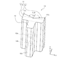
- FIG. 4 is an enlarged perspective view showing the vibration detection apparatus 10 of FIG.
- FIG. 5 is a schematic cross-sectional view showing a state where the vibration detection device 10 of FIG. 4 is cut along the xy plane.
- the holding member 12c is formed in a rectangular parallelepiped shape whose longitudinal direction is the z-axis direction.
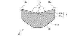
- the attachment portion 11 includes a base portion 11a connected to the holding member 12c, and two projecting portions 11b provided on the surface of the base portion 11a opposite to the holding member 12c.
- the central portion of the base portion 11a in the y-axis direction is connected to the holding member 12c. That is, the base portion 11a is formed in a rectangular parallelepiped shape having the longitudinal direction in the z-axis direction and the length in the y-axis direction longer than that of the holding member 12c.
- the protruding portion 11b has an inner wall 11d located on the opposite side of the sensor holding portion 12, and the two protruding portions 11b form a V-shaped outer wall in the xy sectional view by the inner walls 11d. Yes. That is, the protrusion 11b is formed in a triangular prism shape having the longitudinal direction in the z-axis direction.
- the xy cross section is a right triangle having the inner wall 11d as a hypotenuse.
- a magnet for fixing the vibration detection device 10 to the shell 50 is embedded in the mounting portion 11.
- a magnet having a magnetic force of about 11N to 53N may be used.
- the vibration detection apparatus 10 can be fixed to the compressor 100 in a state where the tip end portion 11 c is in contact with the outer wall of the shell 50.
- a magnet may be embedded in a part of the mounting portion 11 instead of the whole. For example, you may make it provide a magnet in each of the two projection parts 11b.
- the magnet a plate-like or rod-like one can be adopted.
- the magnet is preferably embedded in the main body of the attachment portion 11 so that the longitudinal direction of the magnet matches the longitudinal direction of the attachment portion 11.
- the lightweight vibration detection device 10 can be formed as in the above example, the vibration detection device 10 can be easily fixed to the outer wall where the compression mechanism portion 40 of the shell 50 is located.
- the main body of the mounting portion 11 and the holding member 12c are formed of engineering plastic or fiber reinforced plastic that is superior to general-purpose plastic in performance such as mechanical strength, heat resistance, and wear resistance.
- the surface temperature of the low pressure shell type compressor 100 is lower than that of the high pressure shell type compressor 100. Therefore, when attaching the vibration detection apparatus 10 to the low-pressure shell type compressor 100, the main body of the attachment portion 11 and the holding member 12c can be formed of plastic having relatively low heat resistance. But you may form the attaching part 11 and the holding member 12c by a different material.
- the attachment part 11 may be entirely formed of a magnet.
- each of the two protrusion parts 11b may be formed with the magnet from the attachment part 11. As shown in FIG.
- the central angle ⁇ which is the angle formed between the inner walls 11d of the two protrusions 11b, is set based on the curvature of the shell 50 of various compressors 100. More specifically, for the compressor 100 of various sizes assumed to fix the vibration detection device 10, the center angle ⁇ is defined as the center O and the tip 11 c between the center O and the tip 11 c. The distance is set to be equal to or less than the distance between the center O and the central portion 11e.
- FIG. 5 illustrates an outer wall S, an outer wall M, and an outer wall L as outer walls of the shell 50 having different curvatures, that is, diameters.
- the diameter of the shell 50 increases in the order of the outer wall S, the outer wall M, and the outer wall L.
- the tip portions 11c of the two protrusions 11b are connected to the outer wall S and the outer wall S, respectively. Both the wall M and the outer wall L are in contact.
- the vibration detection device 10 in the state in which the vibration detection device 10 is fixed to the compressor 100, the distal end portions 11c of the two protruding portions 11b are in contact with the outer wall of the shell 50 having any diameter. Therefore, the vibration detection device 10 can be used by being attached to various compressors 100 having different sizes.
- the protrusion 11b has a pointed end 11c. That is, the tip portion 11 c is formed so as to be in line contact with the shell 50 along the axial direction of the rotation shaft in a state where the attachment portion 11 is fixed to the shell 50. Therefore, the dew condensation generated on the surface of the compressor 100 flows from a portion where the protruding portion 11b is not in contact with the shell 50, thereby preventing the dew condensation from adhering to the first vibration sensor 12a and the second vibration sensor 12b. it can. That is, the vibration detection device 10 is fixed to the compressor 100 in a state where the tip portion 11 c located at the tip of the attachment portion 11 is in contact with the shell 50.
- the vibration detection device 10 can fix the attachment portion 11 to the shell 50 in a state where the tip portion 11c is in line contact with the shell 50 along the axial direction of the rotation axis. It is possible to prevent condensation from adhering to the vibration sensor 12a and the second vibration sensor 12b.
- first vibration sensor 12a and the second vibration sensor 12b are provided so that the vibration detection direction is perpendicular to the tip portion 11c formed along the axial direction of the rotation shaft. Accordingly, the first vibration sensor 12a can detect vibration along the tangential direction T by the tip portion 11c contacting the shell 50 along the axial direction of the rotation axis, and the second vibration sensor 12b can Vibration along the center direction Co can be detected.
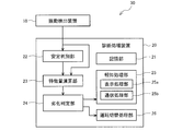
- FIG. 6 is a block diagram showing a functional configuration of the diagnostic processing apparatus 20 of FIG.
- the diagnostic processing device 20 includes a storage unit 21, a stability determination unit 22, a feature amount calculation unit 23, a deterioration determination unit 24, a notification processing unit 25, an operation switching processing unit 26, have.
- the storage unit 21 stores an operation program of the diagnostic processing device 20 and various control parameters.
- the storage unit 21 stores, for example, one or a plurality of deterioration threshold values that serve as a criterion for determining the deterioration of the compressor 100 by the deterioration determination unit 24.
- the stability determination unit 22 determines whether or not the state of the air conditioner 200 is stable. For example, the stability determination unit 22 may determine whether or not the state of the air conditioner 200 is stable by determining whether or not the rotational speed of the compressor 100 has become constant. Further, the stability determination unit 22 may determine whether or not the state of the air conditioner 200 is stable by determining whether or not the state of the refrigeration cycle has been maintained in the same state for a set time or more. .
- the state of the refrigeration cycle is a state such as the temperature and pressure of the refrigerant circulating in the refrigeration cycle, and the set time is set to 3 minutes, for example.
- the stability determination unit 22 may determine the stability of the state of the air conditioner 200 using at least one of the first vibration detection value and the second vibration detection value.
- the feature amount calculator 23 uses at least one of the first vibration detection value detected by the first vibration sensor 12a and the second vibration detection value detected by the second vibration sensor 12b to use the compressor 100.
- the feature amount indicating the state is calculated.
- the feature amount calculation unit 23 has a function of calculating a plurality of different feature amounts at the same timing.
- the feature amount calculation unit 23 may use standard deviation, median value, average value, peak value, impact index, waveform rate, crest factor, skewness, kurtosis, extreme value of skewness, extreme value of kurtosis as the feature amount.
- a value, an extreme value of an average value, an average frequency, an intersection frequency, an extreme value frequency, or the like can be calculated.
- the feature amount calculation unit 23 uses the maximum value or the minimum value as the extreme value when the extreme value of the skewness, the extreme value of the kurtosis, or the average value of the average value is obtained as the feature amount. Further, the feature amount calculation unit 23 can calculate the level of the rotational load of the compressor 100 or the frequency level of the FFT analysis result of the vibration detection value in the tangential direction T as the feature amount. A feature of vibration in the tangential direction T appears in the feature amount calculated based on the first vibration detection value, and a feature of vibration in the circular center direction Co appears in the feature amount calculated based on the second vibration detection value. Appears. The feature amount calculation unit 23 has a function of outputting the calculated feature amount to the deterioration determination unit 24.
- the deterioration determining unit 24 determines the type and degree of deterioration of the compressor 100 based on the feature amount calculated by the feature amount calculating unit 23.
- the deterioration determination unit 24 has a function of performing deterioration determination by using a combination of feature amounts when a plurality of different feature amounts are input from the feature amount calculation unit 23 at the same timing.
- the deterioration determination unit 24 may perform deterioration determination of the compressor 100 using data indicating the operating state of the compressor 100 together with the feature amount.
- the deterioration threshold used by the deterioration determination unit 24 for deterioration determination is, for example, for acquiring one or a plurality of feature value values for each preset rotation speed of the compressor 100 in the initial operation of the air conditioner 200.
- a learning operation may be performed and obtained from data obtained by the learning operation.
- the normal operation may be performed over a certain period, and the deterioration threshold value may be obtained from the feature value obtained during the certain period.
- vibration detection may be performed for the compressor 100 alone, and the deterioration threshold value may be obtained from the vibration detection result. Then, the deterioration threshold value under various conditions may be set by comparing the obtained deterioration threshold value with the mapped value.
- Types of deterioration of the compressor 100 determined by the deterioration determining unit 24 include liquid back of the compressor 100 and damage to the sliding portion of the compression mechanism unit 40. For example, if the rotational load level of the compressor 100 increases linearly or increases rapidly with time, the sliding portion of the compression mechanism 40 is damaged and the frictional resistance is increased. It can be considered. That is, the deterioration determination unit 24 can make a determination regarding the degree of damage of the sliding portion based on the change over time in the rotational load level of the compressor 100.
- whether or not the sliding portion is damaged can be determined by detecting an increase in the input of the compressor 100 or a decrease in the cooling capacity or the heating capacity.
- the state in which the sliding portion is damaged as the input of the compressor 100 increases or the cooling capacity or the like decreases is a state just before the function of the compressor 100 stops. That is, if the compressor 100 is operated to such a state, it is difficult or impossible to repair the compressor 100.
- the deterioration diagnosis device 30 performs deterioration diagnosis using the feature amount calculated based on the vibration detection value by the vibration sensor.
- the level of the rotational load of the compressor 100 is If it fluctuates in several rotation cycles, it can be estimated that the refrigerant sucked in the compressor 100 is backed up.
- the deterioration diagnosis apparatus 30 can determine that the sliding portion of the compression mechanism unit 40 has been damaged by the deterioration determination unit 24. That is, according to the deterioration diagnosis device 30, since a sign of a failure can be accurately detected by using a change in feature over time, it is possible to prevent a situation in which it is difficult to repair the compressor 100. Can do.
- the following can be considered as a method for determining whether or not a liquid back has occurred. That is, for example, when the ratio of the average peak value for 10 revolutions of the compressor 100 and the maximum value during 10 revolutions of the compressor 100 is recorded and this ratio becomes larger than the reference ratio, A method of determining that the refrigerant sucked in the compressor 100 is backed up can be adopted.
- the compressor 100 is rotating once. It is considered that an abnormality that affects the torque fluctuation of the sliding part occurred in the sliding part.
- minute scratches are generated at a plurality of positions on the sliding portion of the compression mechanism 40, frictional resistance due to the plurality of minute scratches is generated a plurality of times during one rotation of the sliding portion. Therefore, when a difference from the normal value occurs in a frequency component higher than the frequency of the compressor 100, it is considered that a minute scratch is generated in the sliding portion. Therefore, in the frequency component higher than the frequency of the compressor 100, when the difference from the normal value is greater than or equal to a certain amount, the deterioration determination unit 24 determines that a minute scratch has occurred on the sliding portion. It is good to do so.
- the crest factor value increases. For this reason, when the crest factor value exceeds a certain value, it is considered that the sliding portion of the compression mechanism 40 is poorly lubricated and the sliding portion is damaged. Therefore, for example, the crest factor is calculated as the feature amount from the vibration acceleration in the tangential direction T and the center direction Co by the feature amount calculation unit 23, and the deterioration determination unit 24 calculates the crest factor calculated in the feature amount calculation unit 23. When the value exceeds the deterioration threshold value, it may be determined that the sliding portion is damaged.
- the notification processing unit 25 notifies the result of determination by the deterioration determination unit 24 to the outside.
- the notification processing unit 25 includes a display processing unit 25a and a communication processing unit 25b.
- the display processing unit 25a causes the display unit 400 to display information indicating the result of determination by the deterioration determination unit 24.
- the communication processing unit 25b communicates with a communication device (not shown) such as a computer provided at a remote monitoring destination by wire or wireless. As the remote monitoring destination, a monitoring center that monitors and manages the operating state of the air conditioner 200 is assumed.
- the communication processing unit 25b has a function of transmitting information indicating the result of determination by the deterioration determination unit 24 to a remote monitoring destination communication device.
- the operation switching processing unit 26 switches the control state of the compressor 100 from normal operation control to life extension operation control when the degree of deterioration of the compressor 100 exceeds a certain standard. That is, the operation switching processing unit 26 transmits a life extension operation command to the control device 300 according to the result of the determination by the deterioration determining unit 24, that is, the degree of deterioration of the compressor 100.
- the life extension operation command is a signal indicating the amount of decrease in the operation frequency of the compressor 100, and includes a signal instructing the stop of the compressor 100 in addition to a signal instructing a decrease in the operation frequency of the compressor 100 by 80%. It is.
- the amount of decrease in the operating frequency of the compressor 100 is set in advance according to the type of deterioration and the degree of deterioration of the compressor 100.
- the storage unit 21 stores a reduction amount table that associates the degree of deterioration of the compressor 100 with the reduction amount of the operating frequency, and the operation switching processing unit 26 refers to the reduction amount table and issues a life extension operation command. You may make it produce
- the decrease amount table may be configured such that the decrease amount of the operating frequency increases as the compressor 100 progresses.
- the control device 300 has a function of reducing the operating frequency of the compressor 100 or stopping the compressor 100 in accordance with the life extension operation command transmitted from the operation switching processing unit 26.
- the operation switching processing unit 26 may have a function of controlling the compressor 100. Then, the operation switching processing unit 26 may reduce the operation frequency of the compressor 100 or stop the compressor 100 according to the determination result by the deterioration determination unit 24.
- the indoor unit 200B includes a speaker, and may include an output unit that outputs sound or sound.
- the display processing unit 25a includes an output processing unit that transmits information indicating the occurrence of damage to the output unit when the deterioration of the compressor 100 is severe and the deterioration determination unit 24 determines that the compressor 100 is damaged. It may be.
- the output unit may output sound or sound based on the information indicating the occurrence of damage transmitted from the output processing unit.
- the notification processing unit 25 may include at least one of the display processing unit 25a, the communication processing unit 25b, and the output processing unit.
- the diagnosis processing device 20 may be configured without including the deterioration determination unit 24, and for example, the communication processing unit 25b may transmit the feature amount calculated by the feature amount calculation unit 23 to an external communication device. In this way, the deterioration diagnosis of the compressor 100 can be performed using the feature amount transmitted from the diagnostic processing device 20 at a remote monitoring destination or the like. Further, the diagnostic processing device 20 is configured without including the feature amount calculation unit 23 and the deterioration determination unit 24. For example, the communication processing unit 25b calculates the feature amount obtained by calculating the vibration detection value detected by the vibration detection device 10. You may make it transmit to an external communication apparatus.
- the feature amount is calculated based on the vibration detection value transmitted from the diagnostic processing device 20 at a remote monitoring destination, and the deterioration diagnosis of the compressor 100 is performed using the calculated feature amount. it can.
- the diagnostic processing device 20 may be configured without including the operation switching processing unit 26.
- the vibration detection device 10 and the diagnostic processing device 20 may be integrally formed. That is, the diagnostic processing device 20 may be provided in the base 11a or may be provided in the sensor holding unit 12.
- the base portion 11a may include a power supply unit that supplies power to the vibration detection device 10 and the diagnostic processing device 20. In this way, the operation of the deterioration diagnosis device 30 alone becomes possible.
- the diagnostic processing device 20 may wirelessly transmit information such as a feature amount or a result of deterioration determination to an external communication device.
- the diagnostic processing device 20 can also be realized by hardware such as a circuit device that realizes each of the functions described above.
- the diagnosis processing device 20 is on an arithmetic device such as a microcomputer, a DSP (Digital Signal Processor), or a CPU (Central Processing Unit). It can also be realized as software executed in
- the storage unit 21 can be configured by a RAM (Random Access Memory) and ROM (Read Only Memory), a PROM (Programmable ROM) such as a flash memory, an HDD (Hard Disk Drive), or the like.
- FIG. 7 is a graph showing the variation rate of the load torque during one rotation for each compressor type.
- the rotation angle [rad] is taken on the horizontal axis, and the fluctuation rate of the load torque is taken on the vertical axis, thereby comparing the fluctuations in the load torque of the compressor 100 employing each method.
- graph A shows the characteristics of the scroll compressor
- graph B shows the characteristics of the single rotary compressor
- graph C shows the characteristics of the twin rotary compressor
- Graph D shows the characteristics of the reciprocating compressor
- graph E shows the characteristics of the helical compressor.
- the compressor 100 has the characteristic according to each form in the load torque pattern in 1 rotation.
- FIG. 8 is a graph showing the load torque of the scroll compressor when it is normal.
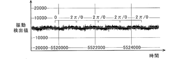
- FIG. 9 is a graph showing vibration detection values in the tangential direction T when the scroll compressor is normal.
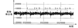
- FIG. 10 is a graph showing the vibration detection value in the tangential direction T when the scroll compressor is deteriorated.
- FIG. 11 is a graph showing a change in the feature amount as the compressor progresses.
- the horizontal axis represents the rotation angle [rad]
- the vertical axis represents the load torque.
- the horizontal axis represents time
- the vertical axis represents the vibration detection value. That is, FIG. 9 and FIG. 10 show the amplitude of the vibration acceleration detected by the first vibration sensor 12a.
- the horizontal axis represents the calculation time
- the vertical axis represents the feature amount.
- the method of the compressor 100 that is, according to the movement pattern of the movable part of the compression mechanism unit 40, at least one feature value is selected, and the selected feature value is calculated and analyzed, thereby compressing.
- the peak value calculated from the vibration detection value shown in FIG. 9 is 5, and the peak value calculated from the vibration detection value shown in FIG.
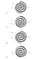
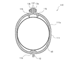
- FIG. 12 is an explanatory diagram showing a schematic cross section of a compression mechanism portion of a scroll compressor. With reference to FIG. 12, the movement of the compression mechanism 40 and the sliding part of the compression mechanism 40 when the compressor 100 is a scroll compressor will be described. As shown in FIG. 12, the compression mechanism unit 40 includes a fixed scroll 41 having a fixed spiral body and an orbiting scroll 42 having an orbiting spiral body.
- the orbiting scroll 42 coupled to the rotating shaft starts rotating and cooperates with the fixed scroll 41 to start compressing the refrigerant gas R. That is, as shown in FIG. 12A, the refrigerant gas R sucked from the suction pipe 101 a flows into the shell 50, and enters the compression mechanism section 40 that includes the fixed scroll 41 and the swing scroll 42. Inhaled. Next, the orbiting scroll 42 orbits in the order of FIG. 12B, FIG. 12C, and FIG. 12D in a state where a part of the side surface is in contact with a part of the side surface of the fixed scroll 41. As a result, the compressed refrigerant gas R is discharged from a discharge port (not shown) provided at the center of the fixed scroll 41 and discharged to the outside of the shell 50 through the discharge pipe 100a.
- a discharge port not shown
- the orbiting scroll 42 orbits along with the rotational movement of the rotary shaft. Since the portion where the fixed scroll 41 and the swing scroll 42 are in contact with each other moves with the turning motion of the swing scroll 42, this portion becomes a sliding portion.
- FIG. 13 is an explanatory diagram showing a schematic cross section of the compression mechanism 40 of the rotary compressor. With reference to FIG. 13, the movement of the compression mechanism 40 and the sliding portion of the compression mechanism 40 when the compressor 100 is a rotary compressor will be described.
- the compression mechanism unit 40 includes a cylinder 43, a rolling piston 44, a vane 45, a vane spring 46, a suction port 47, and a discharge port 48. have.
- a compression chamber 43 a that is a cylindrical space that is open at both ends in the axial direction of the rotary shaft 70.
- the rolling piston 44 is provided in the compression chamber 43 a and rotates in close contact with the inner wall of the cylinder 43 as the eccentric part of the rotating shaft 70 rotates.
- the vane 45 partitions a space formed by the inner wall of the compression chamber 43 a and the outer wall of the rolling piston 44.
- the vane spring 46 is provided in the back pressure chamber 46 a and presses the end of the vane 45 on the compression chamber 43 a side against the outer wall of the rolling piston 44.
- the compression mechanism unit 40 determines the pressure of the refrigerant gas R in the back pressure chamber 46a.
- a differential pressure from the pressure of the refrigerant gas R in the compression chamber 43a is generated. Due to this differential pressure, the vane 45 is moved toward the center of the compression chamber 43 a, so that the end of the vane 45 on the compression chamber 43 a side abuts on the cylindrical outer wall of the rolling piston 44.
- the rolling piston 44 is moved in a state in which a part of the outer wall is in contact with a part of the inner wall of the cylinder 43 in accordance with the rotational movement of the rotating shaft 70, as shown in FIGS. 13B, 13 C, and 13 D. ) In this order. Thereby, the compressed refrigerant gas R is discharged from the discharge port 48 of the compression chamber 43a and discharged to the outside of the shell 50 through the discharge pipe 100a.
- the rolling piston 44 rotates as the rotary shaft 70 rotates. A portion where the inner wall of the cylinder 43 and the outer wall of the rolling piston 44 are in contact with each other, and a portion where the end portion on the compression chamber 43a side of the vane 45 and the outer wall of the rolling piston 44 are in contact with the rotation of the rolling piston 44, Each part becomes a sliding part.
- the compressor 100 has different sliding parts based on the movement of the compression mechanism 40 and the rotational movement of the rotating shaft for each method, and the vibration detection value and the feature amount useful for deterioration diagnosis are also different. ing. That is, in the deterioration diagnosis, there is a compressor 100 in which the vibration detection value in the tangential direction T is more useful, and there is also a compressor 100 in which the vibration detection value in the center direction Co is more useful. Therefore, for example, when diagnosing the deterioration of the compressor 100 in which the vibration detection value in the tangential direction T is more useful, such as a scroll compressor having a rotational motion as a center, the vibration detection device 10 includes the first vibration sensor 12a. You may make it have only.
- the vibration detection device 10 may include only the second vibration sensor 12b.
- the vibration detection device 10 is one biaxial acceleration sensor that detects vibration acceleration in the tangential direction T and the center direction Co, respectively, instead of the first vibration sensor 12a and the second vibration sensor 12b that are uniaxial acceleration sensors. You may make it have.
- the vibration detection device 10 is attached to the shell 50 by the magnetic force of the magnet provided in the attachment portion 11 , but the present invention is not limited to this.
- the attachment portion 11 may be fixed to the shell 50 by welding.
- you may make it attach the attachment part 11 to the shell 50, for example with an adhesive agent.
- a configuration in which the attachment portion 11 is fixed to the shell 50 with a magnet is more preferable.
- 4 and 5 exemplify the case where the xy section of the protrusion 11b is a right triangle, the present invention is not limited to this, and the xy section of the protrusion 11b may be an acute triangle or an obtuse triangle. There may be. 4 and 5 exemplify the case where the two protrusions 11b are continuously formed in the central part 11e, but the present invention is not limited to this, and a gap is formed between the two protrusions 11b. It may be.
- each of the two protruding portions 11b may be constituted by a plurality of protruding members arranged along the z-axis direction.
- each of the plurality of projecting members may have a triangular prism shape, a pyramid shape, or a conical shape.
- the two projecting portions 11b may be formed by combining at least two of a triangular prism-shaped projecting member, a pyramid-shaped projecting member, and a conical projecting member. In this way, a gap is generated between the projecting members, and when the two projecting portions 11b are brought into contact with the shell 50, the plurality of projecting members are in line contact or point with respect to the outer wall of the shell 50, respectively. It will come into contact.
- FIG. 14 is a schematic cross-sectional view showing a state in which the vibration detection device according to Modification 1-1 of Embodiment 1 of the present invention is cut along the xy plane.
- the sensor holding part 12 may be connected to the entire surface of the base part 11a opposite to the protruding part 11b.
- the sensor holding unit 12 may have a trapezoidal cross section along the xy plane.
- FIG. 15 is a schematic cross-sectional view showing a state in which the vibration detection device according to Modification 1-2 of Embodiment 1 of the present invention is cut along the xy plane.
- the vibration detection device 10 may be manufactured exclusively for the compressor 100 having a shell 50 with a fixed curvature. That is, the tip end portions 11 c of the two protrusions 11 b may have contact surfaces that match the curvature of the specific shell 50, and the contact surfaces may contact the shell 50. In this way, since the fixing force of the protrusion 11b to the shell 50 can be strengthened, the vibration detection device 10 can be more stably fixed to the shell 50.
- the two protruding portions 11b may form curved surfaces that curve toward the central portion 11e by the respective inner walls 11d.
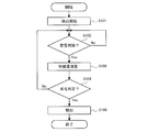
- FIG. 16 is a flowchart showing an operation example of the deterioration diagnosis apparatus of FIG. With reference to FIG. 16, the deterioration diagnosis process of the compressor 100 by the deterioration diagnosis apparatus 30 is demonstrated.
- the deterioration diagnosis device 30 performs deterioration diagnosis of the compressor 100 using both the vibration detection value by the first vibration sensor 12a and the vibration detection value by the second vibration sensor 12b will be described.
- step S101 detection of vibration acceleration in the tangential direction T and the center direction Co by the first vibration sensor 12a and the second vibration sensor 12b is started (step S101). And the stability determination part 22 acquires the vibration acceleration detected by the 1st vibration sensor 12a and the 2nd vibration sensor 12b, and whether the state of the air conditioner 200 was stabilized based on the acquired vibration acceleration. Is determined (step S102).
- the feature amount calculation unit 23 waits until the state of the air conditioner 200 is stabilized (step S102 / No).
- the stability determination unit 22 determines that the state of the air conditioner 200 is stable (Yes in step S102)
- the feature amount calculation unit 23 is detected by the first vibration sensor 12a and the second vibration sensor 12b. Acquire vibration acceleration.
- the feature-value which shows the state of the compressor 100 is calculated using the acquired vibration acceleration (step S103).
- the deterioration determining unit 24 determines deterioration of the compressor 100 based on the feature amount calculated by the feature amount calculating unit 23 (step S104). If the compressor 100 has not deteriorated (step S104 / No), the deterioration determining unit 24 does not perform any processing and returns to step S102. On the other hand, when it is determined that the compressor 100 has deteriorated (Step S104 / Yes), the deterioration determination unit 24 outputs information related to deterioration to the notification processing unit 25 and the operation switching processing unit 26. The notification processing unit 25 notifies information related to deterioration output from the deterioration determination unit 24.
- the notification processing unit 25 executes a display process on the display unit 400 or a transmission process to a remote monitoring destination.
- the operation switching processing unit 26 transmits a life extension operation command to the control device 300. Thereby, the operation switching processing unit 26 switches the control state of the compressor 100 to life extension operation control (step S105).
- the sensor holding unit 12 including at least one of the first vibration sensor 12 a and the second vibration sensor 12 b is used as the compression mechanism unit 40 of the shell 50.
- the vibration sensor 12 a and the second vibration sensor 12 b are formed integrally with the two protrusions 11b disposed on the outer wall where the is located. Therefore, vibration due to the rotational motion of the compression mechanism unit 40 can be detected with high accuracy by the vibration sensor, so that a highly accurate deterioration diagnosis of the compressor 100 can be performed. That is, according to the deterioration diagnosis device 30, it is possible to improve the accuracy of the determination of the non-destructive abnormality diagnosis of the sliding portion of the compression mechanism portion 40.
- the protrusion 11b is configured such that the width in the y-axis direction becomes narrower toward the tip 11c, and the tip 11c contacts the shell 50. That is, each of the tip portions 11c of the plurality of protrusions 11b is formed so as to contact the outer wall of the shell 50 along the axial direction of the rotation shaft. Therefore, the tip portions 11c of the two protruding portions 11b can be brought into line contact with the curved surface of the shell 50. Therefore, since the vibration detection apparatus 10 can be easily installed so that the longitudinal direction of the attachment portion 11 is parallel to the axial direction of the rotation shaft, the vibration detection direction by the vibration sensor can be stabilized.
- tip part 11c of each of the two projection parts 11b can be contacted and fixed to the compressor 100 which has the shell 50 of all the curvatures along the axial direction of a rotating shaft. Furthermore, since the contact part of the projection part 11b and the shell 50 can be made small, the penetration
- Each of the two protrusions 11b is provided with a magnet or is formed of a magnet. Therefore, the vibration detection device 10 can be stably fixed over a long period of time without impairing the cylindricity of the shell 50. And since the vibration detection apparatus 10 can be easily attached or detached with respect to the shell 50, it is intended to improve convenience in a situation where the vibration detection apparatus 10 is fixed to the shell 50 only during the periodic inspection of the compressor 100. Can do.
- the diagnostic processing device 20 can use the optimum feature amount for the vibration pattern based on the movement of the movable part of the compression mechanism unit 40 to determine the deterioration of the compressor 100, and thus detects damage to the compressor 100 with high accuracy. can do. Furthermore, the diagnostic processing device 20 can accurately detect even a sign of a minor failure of the compressor 100 by finely adjusting the feature amount and the deterioration threshold.
- the first vibration sensor 12a and the second vibration sensor 12b of the first embodiment are each arranged so as to coincide with the operation direction of the movable part of the compression mechanism unit 40, so that the detection process is complicated. It can be avoided.
- the vibration sensor is arranged as in Patent Documents 1 and 2
- an accurate vibration detection value cannot be obtained when the movable part of the compression mechanism unit 40 is complicated.
- the first vibration sensor 12a and the second vibration sensor 12b according to the first embodiment coincide with the operation directions of the movable parts of the compression mechanism 40 on the outer wall where the compression mechanism 40 of the shell 50 is located. Therefore, an accurate vibration detection value can be obtained. That is, according to the deterioration diagnosis device 30, even when the movable part of the compression mechanism unit 40 is complicated, it is possible to accurately diagnose the damage of the sliding portion of the compression mechanism unit 40.
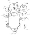
- FIG. FIG. 17 is an external view showing a compressor and a vibration detection device according to Embodiment 2 of the present invention.
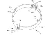
- FIG. 18 is an enlarged perspective view of the vibration detection device of FIG. Based on FIG. 17 and FIG. 18, the configuration of the vibration detection apparatus according to the second embodiment will be described. Constituent members that are the same as or correspond to those of the first embodiment described above are denoted by the same reference numerals and description thereof is omitted.
- the deterioration diagnosis device 30 in the second embodiment includes a vibration detection device 110 and a diagnosis processing device 20, and, like the first embodiment, the compressor 100 of the air conditioner 200 illustrated in FIG. Used by being fixed to.
- the vibration detection device 110 is formed in a band shape, and is configured to be wound around and fixed to the shell 50. More specifically, the base portion 111 a of the attachment portion 111 is formed in an annular shape surrounding the outer wall of the shell 50. Moreover, the attaching part 111 has the two fastening parts 11f fastened with the volt
- the attachment portion 111 has five protrusions 11b.
- One of the attachment portions 111 is disposed to face the two fastening portions 11f that are fastened by the bolts 13a and the nuts 13b.
- Projections 11b are respectively formed at positions adjacent to the two fastening portions 11f.
- Two of the attachment portions 111 are arranged to face each other.
- positioned facing each other, Are arranged on the curved surface opposite to the sensor holding part 12 of the base part 111a at substantially equal intervals.
- at least one of the five protrusions 11b may have a rounded smooth shape.
- the sensor holding part 12 is formed so as to be aligned in the diameter direction of one of the plurality of projecting parts 11b and a base part 111a formed in an annular shape.
- the sensor holding part 12 is arranged in the diameter direction of the base part 111a and the protrusion part 11b arrange
- Other configurations of the vibration detection device 110 are the same as those of the vibration detection device 10 of the first embodiment described above.
- the vibration detection device 110 and the diagnostic processing device 20 may be integrally formed. That is, the diagnostic processing device 20 may be provided in the base 111a or may be provided in the sensor holding unit 12. In addition, the base 111a may include a power supply unit that supplies power to the vibration detection device 110 and the diagnostic processing device 20. In this way, the operation of the deterioration diagnosis device 30 alone becomes possible.
- the communication processing unit 25b has a wireless communication function
- the diagnostic processing device 20 can wirelessly transmit a feature amount or a result of deterioration determination to an external communication device.
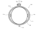
- FIG. 19 is a schematic cross-sectional view showing a state in which the vibration detection device according to Modification 2-1 of Embodiment 2 of the present invention is cut along the xy plane.
- the vibration detection device 110 may include the protrusions 11 b on many portions of the curved surface of the base 111 a opposite to the sensor holding unit 12. In this way, since the contact portion with the shell 50 increases, the fixing force to the shell 50 can be strengthened.
- each of the plurality of protrusions 11b may have a rounded shape such that, for example, the xy section has a semi-cylindrical shape.
- the attachment portion 111 may be configured by combining a rounded protrusion 11b and a protrusion 11b having a sharp tip.
- FIG. 20 is a schematic cross-sectional view showing a state in which the vibration detection device according to Modification 2-2 of Embodiment 2 of the present invention is cut along the xy plane.
- the vibration detection device 110 includes two protrusions 11 b disposed so as to face each other, and includes a distal end portion of each of the two protrusions 11 b and two fastening portions 11 f in the base portion 111 a.
- the peripheral part of the sensor 111 and the peripheral part of the sensor holding part 12 in the base 111 a are configured to contact the shell 50. Even in this case, the vibration detection device 110 is stably fixed to the shell 50.
- the sensor holding portion 12 illustrates a configuration in which the sensor holding portion 12 is disposed at a position facing the two fastening portions 11f, the sensor holding portion 12 includes one of the two protruding portions 11b, You may form so that it may align in the diameter direction of the base 111a. In this way, the condensation generated on the surface of the compressor 100 flows down from the portion of the shell 50 that is not in contact with the protruding portion 11b, so that the adhesion of the condensation to the sensor holding portion 12 can be further suppressed. .
- two rounded protrusions 11b are illustrated, but at least one of the two protrusions 11b may have a shape with a sharp tip.
- FIG. 21 is a schematic cross-sectional view showing a state in which the vibration detection device according to Modification 2-3 of Embodiment 2 of the present invention is cut along the xy plane.
- the attachment portion 111 has a rounded shape, and has one protrusion 11 b that is disposed to face the two fastening portions 11 f.
- projections 11b each having a pointed tip are formed.
- positioned facing the two fastening parts 11f may be a thing of the shape where the front-end
- the sensor holding unit 12 including at least one of the first vibration sensor 12 a and the second vibration sensor 12 b is fixed to the shell 50 2. It is formed integrally with the two protrusions 11b. Therefore, vibration due to the rotational motion of the compression mechanism unit 40 can be detected with high accuracy by the vibration sensor, so that a highly accurate deterioration diagnosis of the compressor 100 can be performed.
- the vibration detection device 110 can be stably fixed to the shell 50.
- the sensor holding part 12 is formed so as to be aligned with one of the plurality of protrusions 11b and the diameter direction of the base part 111a. Therefore, the vibration transmitted from the compression mechanism unit 40 can be directly detected by the vibration sensor, so that a highly accurate vibration detection value can be acquired. Other effects are the same as in the first embodiment.
- the embodiments described above are preferred specific examples of the deterioration diagnosis apparatus and the air conditioner, and the technical scope of the present invention is not limited to these embodiments.
- some or all of the functions of the diagnostic processing device 20 may be incorporated in the control device 300.
- the air conditioner 200 may have two control devices in which the functions of the control device 300 are separated instead of the control device 300. In this case, one control device is provided in the outdoor unit 200A. The other control device may be provided in the indoor unit 200B.
- the air conditioner 200 may have a remote controller for operation connected to the control device 300 by wire or wirelessly, and the display unit 400 may be provided in the remote controller instead of the indoor unit 200B.
- the decompression device 105 is not limited to an electronic expansion valve, and may be any device having a function of decompressing a refrigerant, such as a capillary tube. Moreover, the decompression device 105 may be provided in the indoor unit 200B.
- vibration detection apparatuses 10 and 100 were applied to the compressor of an air conditioner
- the vibration detection apparatuses 10 and 100 are a refrigerator, a freezer showcase, refrigeration. It can be applied to compressors such as showcases and chillers.
Landscapes
- Engineering & Computer Science (AREA)
- Mechanical Engineering (AREA)
- General Engineering & Computer Science (AREA)
- Physics & Mathematics (AREA)
- General Physics & Mathematics (AREA)
- Applications Or Details Of Rotary Compressors (AREA)
- Control Of Positive-Displacement Pumps (AREA)
- Compressor (AREA)
- Measurement Of Mechanical Vibrations Or Ultrasonic Waves (AREA)
Abstract
回転軸の回転運動に伴って駆動する圧縮機構部と外郭をなすシェルとを備えた圧縮機の劣化に関する診断を行う劣化診断装置。劣化診断装置は、前記シェルの前記圧縮機構部が位置する外側壁に固定される振動検出装置を有する。振動検出装置は、圧縮機の振動を検出する振動センサと、振動センサが設けられたセンサ保持部と、センサ保持部が接続された基部と、基部のセンサ保持部とは反対側の面に形成され、外側壁に接触する複数の突起部と、を有している。
Description
本発明は、圧縮機の劣化を診断する劣化診断装置および空気調和機に関する。
従来、空気調和機の運転状態を示すデータから構成機器に生じる異常又は故障を予測し、空気調和機の運転の安定化に活かす技術が提案されている(例えば、特許文献1及び2参照)。特許文献1には、圧縮機の足部に取り付けられた加速度センサによる振動検出値をもとに圧縮機の寿命を予測するという技術が開示されている。また、特許文献2の空気調和機は、圧縮機のシェルの周面にターミナルカバーを有しており、ターミナルカバー内に設けられた加速度センサによる振動検出値が異常を示したときに、圧縮機を停止するように構成されている。
しかしながら、圧縮機の足部は、圧縮機構部の回転運動などに起因した圧縮機の振動が伝わりにくい位置である。また、電源接続部を覆うターミナルカバーは、一般に、圧縮機の振動が伝わりにくい位置に設けられる。加えて、ターミナルカバーは、固定強度が弱いため、ターミナルカバー内の加速度センサによる振動検出値にノイズ等が混入しやすく、検出精度に問題があった。すなわち、特許文献1および2に開示された技術では、圧縮機構部の回転運動などによる振動を精度よく検出することができないため、圧縮機の劣化度合を細かく診断することができないという課題がある。
本発明は、上記のような課題を解決するためになされたものであり、圧縮機構部の回転運動などによる振動を精度よく検出し、圧縮機の高精度な劣化診断を行う劣化診断装置および空気調和機を提供することを目的とする。
本発明に係る劣化診断装置は、回転軸の回転運動に伴って駆動する圧縮機構部と、外郭をなすシェルとを備えた圧縮機の劣化に関する診断を行う劣化診断装置であって、シェルの圧縮機構部が位置する外側壁に固定される振動検出装置を備え、振動検出装置は、圧縮機の振動を検出する振動センサと、振動センサが設けられたセンサ保持部と、センサ保持部が接続された基部と、基部のセンサ保持部とは反対側の面に形成され、外側壁に接触する複数の突起部と、を有するものである。
本発明に係る空気調和機は、回転軸の回転運動に伴って駆動する圧縮機構部を備え、冷媒を圧縮する圧縮機と、熱媒体と冷媒とを熱交換させる熱源側熱交換器と、冷媒の流量を調整する減圧装置と、室内の空気と冷媒とを熱交換させる利用側熱交換器とが冷媒配管により接続され、冷媒が循環する冷凍サイクルと、上記の劣化診断装置と、を有するものである。
本発明によれば、振動センサを備えたセンサ保持部が、シェルの圧縮機構部が位置する外側壁に接触する複数の突起部と一体的に形成されていることから、圧縮機構部の回転運動などによる振動を振動センサによって精度よく検出することができるため、圧縮機の高精度な劣化診断を行うことができる。
実施の形態1.
図1は、本発明の実施の形態1に係る空気調和機および劣化診断装置の構成図である。図1に示すように、空気調和機200は、屋外に配置される室外機200Aと、室内に配置される室内機200Bと、を有している。室外機200Aは、圧縮機100と、圧縮機100の吸入側に接続された吸入マフラ101と、圧縮機100の吐出側に接続された四方弁103と、を有している。また、室外機200Aは、例えばフィンアンドチューブ型熱交換器からなり、外気と冷媒とを熱交換させる熱源側熱交換器104と、例えば電動膨張弁からなり、冷媒の流量を調整する減圧装置105と、を有している。室内機200Bは、例えばフィンアンドチューブ型熱交換器からなり、室内の空気と冷媒とを熱交換させる利用側熱交換器106を有している。すなわち、空気調和機200は、圧縮機100、吸入マフラ101、四方弁103、熱源側熱交換器104、減圧装置105、および利用側熱交換器106が冷媒配管150により接続され、冷媒が循環する冷凍サイクルを有している。
図1は、本発明の実施の形態1に係る空気調和機および劣化診断装置の構成図である。図1に示すように、空気調和機200は、屋外に配置される室外機200Aと、室内に配置される室内機200Bと、を有している。室外機200Aは、圧縮機100と、圧縮機100の吸入側に接続された吸入マフラ101と、圧縮機100の吐出側に接続された四方弁103と、を有している。また、室外機200Aは、例えばフィンアンドチューブ型熱交換器からなり、外気と冷媒とを熱交換させる熱源側熱交換器104と、例えば電動膨張弁からなり、冷媒の流量を調整する減圧装置105と、を有している。室内機200Bは、例えばフィンアンドチューブ型熱交換器からなり、室内の空気と冷媒とを熱交換させる利用側熱交換器106を有している。すなわち、空気調和機200は、圧縮機100、吸入マフラ101、四方弁103、熱源側熱交換器104、減圧装置105、および利用側熱交換器106が冷媒配管150により接続され、冷媒が循環する冷凍サイクルを有している。
圧縮機100は、低圧のガス状態の冷媒を吸入し、高圧のガス状態の冷媒に圧縮するものである。圧縮機100は、インバータ制御により運転周波数を任意に変化させることができるものであってよいし、運転周波数を変化させる機能をもたない一定速のものであってもよい。圧縮機100としては、スクロール式圧縮機、ロータリー式圧縮機、レシプロ式圧縮機、ロータリー式圧縮機、ヘリカル式圧縮機、およびターボ式圧縮機など、種々の圧縮機を採用することができる。四方弁103は、圧縮機100からの冷媒の流れを切り替えるものである。四方弁103は、例えば、暖房運転時には図1の実線側に接続され、冷房運転時には図1の破線側に接続される。
室外機200Aは、冷凍サイクルを制御する制御装置300を有している。つまり、制御装置300は、圧縮機100の運転周波数、四方弁103の切替処理、および減圧装置105の開度などを制御するものである。そして、室外機200Aには、劣化診断装置30が設けられている。劣化診断装置30は、振動検出装置10と診断処理装置20とにより構成されている。
振動検出装置10と診断処理装置20とは、有線又は無線により接続されている。すなわち、診断処理装置20は、振動検出装置10から有線又は無線により、第1振動センサ12aおよび第2振動センサ12bによる振動検出値を取得するように構成されている。室内機200Bは、例えば液晶ディスプレイ(LCD:liquid crystal display)からなる表示部400を有している。
図2は、図1の圧縮機および振動検出装置を示す外観図である。図3は、図2の圧縮機構部およびシェルをxy平面で切断した断面を概略的に示す説明図である。図2に示すように、圧縮機100は、シェル50と足部60とを有している。シェル50は、圧縮機100の外郭をなしている。また、圧縮機100は、シェル50の内部に、回転軸(図示せず)の回転運動に伴って駆動する圧縮機構部40を有している。圧縮機構部40は、回転軸によって電動機(図示せず)と連結されており、回転軸は、電動機の回転力を圧縮機構部40に伝達するようになっている。圧縮機100には吐出管100aが設けられており、吸入マフラ101には吸入管101aが設けられている。
圧縮機構部40は、内部の可動部品の回転運動又は往復運動などにより振動し、その振動がシェル50に伝達される。シェル50のうち、圧縮機構部40の外周に位置する部分には、圧縮機構部40の振動がより強く伝達される。そして、圧縮機構部40は、一定周期で所定の運動パターンを繰り返すため、シェル50には、圧縮機構部40の可動部品の運動に起因した振動パターンが伝達される。よって、振動検出装置10は、図2に示すように、シェル50の圧縮機構部40が位置する外側壁に固定されている。
振動検出装置10は、第1振動センサ12aおよび第2振動センサ12bと、保持部材12cとを有するセンサ保持部12を備えている。すなわち、センサ保持部12は、保持部材12cに、第1振動センサ12aと第2振動センサ12bとが設けられたものである。また、振動検出装置10は、センサ保持部12に接続された取付部11を有している。取付部11は、振動検出装置10を圧縮機100に固定した状態において、センサ保持部12よりも圧縮機100側となる。
第1振動センサ12aおよび第2振動センサ12bは、振動検出方向が、圧縮機構部40の可動部品の運動方向と一致するように配置されている。圧縮機構部40の可動部品の運動方向には、圧縮機構部40の回転軌道の接線の方向である接線方向Tと、シェル50の外側壁から圧縮機構部40の中心へ向かう方向である円心方向Coとがある。そして、第1振動センサ12aは、振動検出方向が接線方向Tと一致するように配置されている。第2振動センサ12bは、振動検出方向が円心方向Coと一致するように配置されている。すなわち、第1振動センサ12aは、圧縮機構部40の可動部品の回転運動に起因する圧縮機100の接線方向Tに沿った振動を第1振動検出値として検出するものである。第2振動センサ12bは、圧縮機構部40の可動部品の往復運動に起因する圧縮機100の円心方向Coに沿った振動を第2振動検出値として検出するものである。
図2において、接線方向Tはx軸方向に平行であり、円心方向Coはy軸方向に平行であり、回転軸の軸方向はz軸方向に相当する。以下の各図においても同様である。図3に示すように、接線方向Tは、xy断面において、シェル50の直径方向に垂直な方向であり、円心方向Coは、xy断面において、シェル50の直径方向に相当する。
第1振動センサ12aおよび第2振動センサ12bは、振動加速度を検出する加速度センサのうち、半導体方式のMEMS(Micro Electro Mechanical System)センサである。特に、本実施の形態1では、シェル50の表面温度の上昇度合を考慮し、第1振動センサ12aおよび第2振動センサ12bとして、静電容量型もしくはピエゾ抵抗型のMEMSセンサを用いている。
図4は、図2の振動検出装置10を拡大して示した斜視図である。図5は、図4の振動検出装置10をxy平面で切断した状態を示す概略断面図である。図4および図5を参照して、振動検出装置10の具体的な構造について説明する。保持部材12cは、z軸方向を長手方向とする直方体状に形成されている。取付部11は、保持部材12cに接続された基部11aと、基部11aの保持部材12cとは反対側の面に設けられた2つの突起部11bと、を有している。
図4および図5の例では、基部11aのy軸方向における中央部分が、保持部材12cに接続されている。すなわち、基部11aは、z軸方向を長手方向とし、y軸方向の長さが保持部材12cよりも長い直方体状に形成されている。突起部11bは、センサ保持部12とは反対側に位置する内壁11dを有しており、2つの突起部11bは、それぞれの内壁11dにより、xy断面視におけるV字状の外壁を形成している。すなわち、突起部11bは、z軸方向を長手方向とする三角柱状に形成されており、図4および図5の例では、xy断面が内壁11dを斜辺とする直角三角形となっている。
取付部11には、振動検出装置10をシェル50に固定するための磁石が埋め込まれている。例えば、振動検出装置10の重さが2g~10gの場合、11N~53N程度の磁力を有する磁石を用いればよい。これにより、先端部11cがシェル50の外側壁に接触した状態で、振動検出装置10を圧縮機100に固定することができる。
振動検出装置10をシェル50に安定的に固定する磁力が得られれば、取付部11の全体ではなく一部に磁石を埋め込むようにしてもよい。例えば、2つの突起部11bの各々に磁石を設けるようにしてもよい。磁石としては、板状あるいは棒状のものを採用することができる。この場合、磁石の長手方向が、取付部11の長手方向と一致するように、取付部11の本体に磁石を埋め込むようにするとよい。
ところで、近年は、従来と比べて耐熱性および検出精度が高く、かつ小型で安価な加速度センサが開発されている。よって、上記例のように軽量な振動検出装置10を形成することができることため、シェル50の圧縮機構部40が位置する外側壁に、振動検出装置10を簡単に固定して用いることができる。
取付部11の本体および保持部材12cは、機械的強度、耐熱性、および耐摩耗性などの性能が汎用プラスチックよりも優れたエンジニアリングプラスチック又は繊維強化プラスチックなどにより形成されている。ここで、低圧シェル型の圧縮機100は、高圧シェル型の圧縮機100よりも表面温度が低くなる。そのため、振動検出装置10を低圧シェル型の圧縮機100に取り付ける場合、取付部11の本体および保持部材12cは、耐熱性の比較的低いプラスチックにより形成することができる。もっとも、取付部11と保持部材12cとを異なる材料により形成してもよい。例えば、取付部11は、全体が磁石によって形成されていてもよい。また、取付部11は、2つの突起部11bの各々が磁石によって形成されていてもよい。
本実施の形態1において、2つの突起部11bの内壁11d同士がなす角である中心角θは、種々の圧縮機100のシェル50の曲率をもとに設定されている。より具体的に、中心角θは、振動検出装置10を固定することが想定される様々な大きさの圧縮機100について、シェル50の中心を中心Oとすると、中心Oと先端部11cとの距離が、中心Oと中央部11eとの距離以下となるように設定されている。
図5には、曲率すなわち径の異なるシェル50の外側壁として、外側壁S、外側壁M、および外側壁Lを例示している。シェル50の径は、外側壁S、外側壁M、外側壁Lの順に大きくなっているが、図5に示すように、2つの突起部11bの双方の先端部11cが、外側壁S、外側壁M、および外側壁Lのいずれにも接触している。すなわち、振動検出装置10は、圧縮機100に固定された状態において、あらゆる径のシェル50の外側壁に、2つの突起部11bのそれぞれの先端部11cが接触するようになっている。したがって、振動検出装置10は、大きさの異なる多様な圧縮機100に取り付けて用いることができる。
さらに、突起部11bは、先端部11cが尖った形状となっている。すなわち、先端部11cは、取付部11をシェル50に固定した状態において、回転軸の軸方向に沿ってシェル50に線接触するように形成されている。そのため、圧縮機100の表面に発生した結露は、突起部11bがシェル50に接触していない部分から流れることから、第1振動センサ12aおよび第2振動センサ12bへの結露の付着を防ぐことができる。すなわち、振動検出装置10は、取付部11の先端に位置する先端部11cをシェル50に接触させた状態で、圧縮機100に固定される。そのため、特に、第1振動センサ12aおよび第2振動センサ12bが通信線などにより診断処理装置20に接続されている場合において、結露の侵入による第1振動センサ12aおよび第2振動センサ12bの故障等を防ぐことができる。ここで、先端部11cは、なめらかに形成され、丸みを帯びていてもよい。このようにしても、振動検出装置10は、先端部11cを回転軸の軸方向に沿ってシェル50に線接触させた状態で、取付部11をシェル50に固定することができるため、第1振動センサ12aおよび第2振動センサ12bへの結露の付着を防止することができる。
また、第1振動センサ12aおよび第2振動センサ12bは、振動検出方向が、回転軸の軸方向に沿って形成された先端部11cに対して直角となるように設けられている。したがって、先端部11cが回転軸の軸方向に沿ってシェル50に接触することにより、第1振動センサ12aは、接線方向Tに沿った振動を検出することができ、第2振動センサ12bは、円心方向Coに沿った振動を検出することができる。
図6は、図1の診断処理装置20の機能的構成を示すブロック図である。図6に示すように、診断処理装置20は、記憶部21と、安定判別部22と、特徴量演算部23と、劣化判定部24と、報知処理部25と、運転切替処理部26と、を有している。記憶部21には、診断処理装置20の動作プログラムおよび各種制御パラメータなどが記憶されている。記憶部21には、例えば、劣化判定部24による圧縮機100の劣化判定の基準となる一又は複数の劣化閾値が格納されている。
安定判別部22は、空気調和機200の状態が安定したか否かを判別するものである。例えば、安定判別部22は、圧縮機100の回転数が一定になったか否かを判定することにより、空気調和機200の状態が安定したか否かを判別するようにしてもよい。また、安定判別部22は、冷凍サイクルの状態が設定時間以上同じ状態で維持されたか否かを判定することにより、空気調和機200の状態が安定したか否かを判別するようにしてもよい。ここで、冷凍サイクルの状態とは、冷凍サイクル内を循環する冷媒の温度および圧力等の状態であり、設定時間は、例えば3分に設定される。なお、安定判別部22は、第1振動検出値および第2振動検出値のうちの少なくとも一つを用いて、空気調和機200の状態の安定性を判別するようにしてもよい。
特徴量演算部23は、第1振動センサ12aにおいて検出された第1振動検出値、および第2振動センサ12bにおいて検出された第2振動検出値のうちの少なくとも一つを用いて、圧縮機100の状態を示す特徴量を演算するものである。特徴量演算部23は、複数の異なる特徴量を同じタイミングで演算する機能を有している。特徴量演算部23は、特徴量として、例えば、標準偏差、中央値、平均値、ピーク値、衝撃指数、波形率、波高率、歪度、尖度、歪度の極値、尖度の極値、平均値の極値、平均周波数、交差頻度、又は極値頻度などを演算することができる。特徴量演算部23は、特徴量として、歪度の極値、尖度の極値、又は平均値の極値を求める場合、極値として極大値又は極小値を用いる。また、特徴量演算部23は、特徴量として、圧縮機100の回転負荷のレベル、又は接線方向Tにおける振動検出値のFFT解析結果の周波数のレベルなどを演算することができる。第1振動検出値をもとに演算した特徴量には、接線方向Tにおける振動の特徴が現れ、第2振動検出値をもとに演算した特徴量には、円心方向Coにおける振動の特徴が現れる。特徴量演算部23は、演算した特徴量を劣化判定部24へ出力する機能を有している。
劣化判定部24は、特徴量演算部23において演算された特徴量をもとに、圧縮機100の劣化の種類および劣化度合を判定するものである。劣化判定部24は、特徴量演算部23から複数の異なる特徴量を同じタイミングで入力した場合、各特徴量を組み合わせて用いることにより、劣化判定を行う機能を有している。劣化判定部24は、特徴量と共に、圧縮機100の運転状態などを示すデータを用いて、圧縮機100の劣化判定を行うようにしてもよい。
劣化判定部24が劣化判定に用いる劣化閾値は、例えば、空気調和機200の運転初期において、予め設定された圧縮機100の回転数ごとに、一又は複数の特徴量の値を取得するための学習運転を行い、この学習運転によって得られたデータから求めるようにしてもよい。また、一定の期間に亘って通常運転を行い、一定の期間に得られた特徴量の値から劣化閾値を求めるようにしてもよい。さらに、凝縮温度、蒸発温度、および圧縮機100の回転数を予め設定した上で、圧縮機100単体での振動検出を実行し、振動検出の結果から劣化閾値を求めるようにしてもよい。そして、求めた劣化閾値とマップ化した値と比較することにより、種々の条件下での劣化閾値を設定するようにしてもよい。
ここで、劣化判定部24による劣化判定に関する劣化の種類と劣化度合について具体的に例示する。劣化判定部24が判定する圧縮機100の劣化の種類には、圧縮機100の液バックおよび圧縮機構部40の摺動部の損傷などがある。例えば、圧縮機100の回転負荷のレベルが時間経過により線形的に増加し、又は急激に上昇していくならば、圧縮機構部40の摺動部に損傷が生じ、摩擦抵抗が増加していっていることが考えられる。すなわち、劣化判定部24は、圧縮機100の回転負荷のレベルの経時的な変化をもとに、摺動部の損傷度合に関する判定を行うことができる。
ところで、摺動部に損傷が生じたか否かについては、圧縮機100の入力の増大、又は冷房能力もしくは暖房能力の低下を検知することによって判定することもできる。しかし、圧縮機100の入力が増大するほど、もしくは冷房能力などが低下するほど摺動部が損傷した状態は、圧縮機100の機能が停止する直前のような状態である。つまり、このような状態まで圧縮機100を運転させてしまうと、圧縮機100の修復が困難又は不可能となってしまう。
これに対し、本実施の形態1の劣化診断装置30は、振動センサによる振動検出値をもとに演算した特徴量を用いて劣化診断を行うため、例えば、圧縮機100の回転負荷のレベルが数回転周期で変動するようならば、圧縮機100の吸入冷媒が液バックしていると推定することができる。また、劣化診断装置30は、圧縮機100の回転負荷のレベルが劣化閾値を超えた場合に、劣化判定部24によって圧縮機構部40の摺動部に損傷が発生したと判定することができる。すなわち、劣化診断装置30によれば、特徴量の経時的な変化を用いて、故障の徴候を精度よく検出することができるため、圧縮機100の修復が困難になるといった事態を未然に防ぐことができる。
液バックが発生しているか否かを判定する方法としては、以下のようなものも考えられる。すなわち、例えば、圧縮機100の10回転分のピーク値の平均と、圧縮機100の10回転中の最大値との比を記録し、この比が基準となる比率よりも大きくなったときに、圧縮機100の吸入冷媒が液バックしていると判定する方法を採ることができる。
また、圧縮機100の接線方向Tの振動のFFT(Fast Fourier Transform)解析結果のn次の周波数のレベル、又はn次以外の周波数のレベルが劣化閾値より上昇すると、圧縮機100の一回転中のトルク変動に影響を及ぼす程度の異常が摺動部に生じたと考えられる。特に、圧縮機構部40の摺動部の複数箇所に微小な傷が生じた場合は、複数の微小な傷による摩擦抵抗が、摺動部の一回転中に複数回生じる。そのため、圧縮機100の周波数よりも高い周波数成分において正常値との違いが生じた場合は、摺動部に微小な傷が生じていると考えられる。よって、圧縮機100の周波数よりも高い周波数成分において、正常値との差が一定量以上に生じた場合に、劣化判定部24が、摺動部に微小な傷が発生していると判定するようにするとよい。
加えて、振動検出値に衝撃成分が混じった場合は、例えば波高率の値が大きくなる。そのため、波高率の値が一定値を超えた場合は、圧縮機構部40の摺動部の潤滑不良が発生し、摺動部に損傷が生じていることが考えられる。よって、例えば、特徴量演算部23により接線方向Tおよび円心方向Coの振動加速度から特徴量として波高率を演算するようにし、劣化判定部24が、特徴量演算部23において演算された波高率が劣化閾値を超えた場合に、摺動部に損傷が生じていると判定するようにしてもよい。
報知処理部25は、劣化判定部24による判定の結果を外部に報知するものである。図6の例において、報知処理部25は、表示処理部25aと通信処理部25bとを有している。表示処理部25aは、劣化判定部24による判定の結果を示す情報を表示部400に表示させるものである。通信処理部25bは、遠隔監視先に設けられたコンピュータなどの通信機器(図示せず)との間で、有線又は無線により通信を行うものである。遠隔監視先としては、空気調和機200の動作状態を監視して管理する監視センターなどが想定される。通信処理部25bは、劣化判定部24による判定の結果を示す情報を遠隔監視先の通信機器に送信する機能を有している。
運転切替処理部26は、圧縮機100の劣化度合が一定の基準を超えた場合に、圧縮機100の制御状態を、通常運転制御から延命運転制御に切り替えるものである。すなわち、運転切替処理部26は、劣化判定部24による判定の結果、すなわち圧縮機100の劣化度合に応じて、制御装置300に延命運転指令を送信するものである。延命運転指令は、圧縮機100の運転周波数の低下量を示す信号であり、圧縮機100の運転周波数の8割低下を指示する信号などの他に、圧縮機100の停止を指示する信号も含まれる。圧縮機100の運転周波数の低下量は、圧縮機100の劣化の種類および劣化度合に応じて予め設定されている。例えば、記憶部21に、圧縮機100の劣化度合と運転周波数の低下量とを関連づけた低下量テーブルを格納しておき、運転切替処理部26が、低下量テーブルを参照して延命運転指令を生成するようにしてもよい。低下量テーブルは、圧縮機100の劣化が進むにつれて、運転周波数の低下量が大きくなるように構成するとよい。
制御装置300は、運転切替処理部26から送信される延命運転指令に応じて、圧縮機100の運転周波数を低下させ、又は圧縮機100を停止させる機能を有している。もっとも、運転切替処理部26は、圧縮機100を制御する機能を有するようにしてもよい。そして、運転切替処理部26が、劣化判定部24による判定の結果に応じて、圧縮機100の運転周波数を低下させ、又は圧縮機100を停止させるようにしてもよい。
ここで、室内機200Bは、スピーカを含んで構成され、音又は音声を出力する出力部を有していてもよい。表示処理部25aは、圧縮機100の劣化がひどく、劣化判定部24において圧縮機100に損傷が発生したと判定された場合、出力部に損傷発生を示す情報を送信する出力処理部を有していてもよい。そして、出力部は、出力処理部から送信された損傷発生を示す情報をもとに、音又音声を出力するようにしてもよい。ここで、報知処理部25は、表示処理部25a、通信処理部25b、および出力処理部のうちの少なくとも1つを有するようにしてもよい。
診断処理装置20は、劣化判定部24を含めずに構成し、例えば通信処理部25bが、特徴量演算部23において演算された特徴量を外部の通信機器へ送信するようにしてもよい。このようにすれば、遠隔監視先などにおいて、診断処理装置20から送信された特徴量を用いて圧縮機100の劣化診断を行うことができる。また、診断処理装置20は、特徴量演算部23および劣化判定部24を含めずに構成し、例えば通信処理部25bが、振動検出装置10において検出された振動検出値を演算された特徴量を外部の通信機器へ送信するようにしてもよい。このようにすれば、遠隔監視先などにおいて、診断処理装置20から送信された振動検出値をもとに特徴量を演算し、演算した特徴量を用いて圧縮機100の劣化診断を行うことができる。さらに、診断処理装置20は、運転切替処理部26を含めずに構成してもよい。
振動検出装置10と診断処理装置20とは、一体的に形成されていてもよい。すなわち、診断処理装置20は、基部11aに設けられていてもよく、センサ保持部12に設けられていてもよい。そして、基部11aは、振動検出装置10および診断処理装置20に電源を供給する電源部を有するようにするとよい。このようにすれば、劣化診断装置30単体での動作が可能となる。通信処理部25bが無線通信機能を有する場合、診断処理装置20は、特徴量又は劣化判定の結果などの情報を外部の通信機器へ無線で送信するようにしてもよい。
診断処理装置20は、上記の各機能を実現する回路デバイスなどのハードウェアで実現することもできるし、例えば、マイコン、DSP(Digital Signal Processor)、又はCPU(Central Processing Unit)等の演算装置上で実行されるソフトウェアとして実現することもできる。また、記憶部21は、RAM(Random Access Memory)およびROM(Read Only Memory)、フラッシュメモリ等のPROM(Programmable ROM)、又はHDD(Hard Disk Drive)等により構成することができる。
図7は、圧縮機の形式毎の1回転中の負荷トルクの変動率を示すグラフである。図7では、横軸に回転角度[rad]をとり、縦軸に負荷トルクの変動率をとることにより、各方式を採った圧縮機100の負荷トルクの変動を比較している。図7において、グラフAはスクロール式圧縮機の特性を示し、グラフBはシングルロータリー式圧縮機の特性を示し、グラフCはツインロータリー式圧縮機の特性を示す。また、グラフDはレシプロ式圧縮機の特性を示し、グラフEはヘリカル式圧縮機の特性を示す。このように、圧縮機100は、1回転中の負荷トルクパターンに、各形式に応じた特徴がある。
図8は、スクロール式圧縮機の正常時の負荷トルクを示すグラフである。図9は、スクロール式圧縮機の正常時における接線方向Tの振動検出値を示すグラフである。図10は、スクロール式圧縮機の劣化時における接線方向Tの振動検出値を示すグラフである。図11は、圧縮機の劣化進行に伴う特徴量の変化を示すグラフである。図8では、横軸に回転角度[rad]をとり、縦軸に負荷トルクをとっている。図9および図10では、横軸に時間をとり、縦軸に振動検出値をとっている。すなわち、図9および図10には、第1振動センサ12aによって検出された振動加速度の振幅が示されている。図11では、横軸に演算回をとり、縦軸に特徴量をとっている。
ここで、1回転中の負荷トルクパターンには、回転運動などを行う圧縮機構部40による影響が大きく現れるため、図8と図9とから分かるように、圧縮機100の接線方向Tの振動と負荷トルクパターンとの相関が高くなっている。
例えば、液バック又は油上がりによる圧縮機100への返油量減少などにより、圧縮機構部40の摺動部の油が枯渇し、摺動部に損傷が生じた場合、図10に示すように、接線方向Tの振動パターンが変化する。したがって、第1振動検出値を用いて特徴量を演算し、振動波形の計上を数値化すると、図11に示すように、圧縮機100は、正常に運転している正常区間と、劣化した状態で運転している劣化区間とにおいて、値が変化する特性をもつ特徴量が存在する。こうした特徴量は、圧縮機100の正常時と劣化時とにおいて、特徴量の確率密度分布の中央値と標準偏差とが異なっている。すなわち、圧縮機100の方式などに応じて、つまり圧縮機構部40の可動部品の運動パターンに応じて、少なくとも1つの特徴量を選定し、選定した特徴量を演算して解析することにより、圧縮機100の正常と劣化とを区別することができる。なお、図9に示す振動検出値から演算した波高値は5となり、図10に示す振動検出値から演算した波高値は7~8となる。
ここで、上述した圧縮機構部40の摺動部に関して、図12及び図13に基づき、スクロール式圧縮機およびロータリー式圧縮機の場合の構成例について説明する。
図12は、スクロール式圧縮機の圧縮機構部の概略断面を示す説明図である。図12を参照して、圧縮機100がスクロール式圧縮機である場合の、圧縮機構部40の動き、および圧縮機構部40の摺動部について説明する。図12に示すように、圧縮機構部40は、固定渦巻体を有する固定スクロール41と、揺動渦巻体を有する揺動スクロール42と、を備えている。
圧縮機100の回転軸(図示せず)が回転すると、回転軸に結合された揺動スクロール42が回転を始め、固定スクロール41と協動して冷媒ガスRの圧縮を開始する。すなわち、図12(a)のように、吸入管101aから吸引された冷媒ガスRは、シェル50内に流入され、固定スクロール41と揺動スクロール42とを含んで形成された圧縮機構部40へ吸入される。次いで、揺動スクロール42が、側面の一部が固定スクロール41の側面の一部と接した状態で、図12(b)、図12(c)、図12(d)の順に旋回運動する。これにより、圧縮された冷媒ガスRが、固定スクロール41の中心部に設けられた吐出口(図示せず)から排出され、吐出管100aを介してシェル50の外部に吐出される。
このように、スクロール式圧縮機の圧縮機構部40では、揺動スクロール42が、回転軸の回転運動に伴って旋回運動する。固定スクロール41と揺動スクロール42とが接する部分は、揺動スクロール42の旋回運動に伴って移動するため、当該部分が摺動部となる。
図13は、ロータリー式圧縮機の圧縮機構部40の概略断面を示す説明図である。図13を参照して、圧縮機100がロータリー式圧縮機である場合の、圧縮機構部40の動き、および圧縮機構部40の摺動部について説明する。
図13に示すように、圧縮機構部40は、シリンダ43と、ローリングピストン44と、ベーン45と、ベーンスプリング46と、吸込口47と、吐出口48と、を有している。を有している。シリンダ43の内部には、回転軸70の軸方向の両端が開口された円筒状の空間である圧縮室43aが設けられている。ローリングピストン44は、圧縮室43a内に設けられており、回転軸70の偏心部の回転運動に伴い、シリンダ43の内壁に密接して回転するものである。ベーン45は、圧縮室43aの内壁とローリングピストン44の外壁とによって形成される空間を仕切るものである。ベーンスプリング46は、背圧室46aに設けられており、ベーン45の圧縮室43a側の端部をローリングピストン44の外壁に押圧するものである。
圧縮機構部40は、図13(a)のように、シェル50内の冷媒ガスRが、吸込口47を介して背圧室46aに流入すると、背圧室46a内の冷媒ガスRの圧力と圧縮室43a内の冷媒ガスRの圧力との差圧が生じる。この差圧により、ベーン45が圧縮室43aの中心に向って動かされるため、ベーン45の圧縮室43a側の端部は、ローリングピストン44の円筒状の外壁に当接する。そして、ローリングピストン44は、回転軸70の回転運動に伴い、外壁の一部がシリンダ43の内壁の一部に接した状態で、図13(b)、図13(c)、図13(d)の順に回転する。これにより、圧縮された冷媒ガスRが、圧縮室43aの吐出口48から排出され、吐出管100aを介してシェル50の外部に吐出される。
このように、ロータリー式圧縮機の圧縮機構部40では、ローリングピストン44が、回転軸70の回転運動に伴って回転する。シリンダ43の内壁とローリングピストン44の外壁とが接する部分、およびベーン45の圧縮室43a側の端部とローリングピストン44の外壁とが接する部分は、ローリングピストン44の回転に伴って移動し、これらの各部分が摺動部となる。
上述した例のように、圧縮機100は、方式ごとに圧縮機構部40の動き及び回転軸の回転運動に基づく摺動部が異なっており、劣化診断に有用な振動検出値および特徴量も異なっている。すなわち、劣化診断に際して、接線方向Tの振動検出値の方が有用な圧縮機100もあれば、円心方向Coの振動検出値の方が有用な圧縮機100もある。そのため、例えば、回転運動が中心となるスクロール圧縮機のように、接線方向Tの振動検出値の方が有用な圧縮機100の劣化を診断する場合、振動検出装置10は、第1振動センサ12aのみを有するようにしてもよい。一方、接線方向Tの振動検出値の方が有用な圧縮機100の劣化を診断する場合、振動検出装置10は、第2振動センサ12bのみを有するようにしてもよい。また、振動検出装置10は、1軸加速度センサである第1振動センサ12aおよび第2振動センサ12bの代わりに、接線方向Tおよび円心方向Coの振動加速度をそれぞれ検出する1つの2軸加速度センサを有するようにしてもよい。
上記の説明では、取付部11に設けられた磁石の磁力によって、振動検出装置10をシェル50に取り付ける場合を例示したが、これに限定されるものではない。例えば、取付部11を溶接によりシェル50に固定するようにしてもよい。また、取付部11を、例えば接着剤によりシェル50に取り付けるようにしてもよい。ただし、溶接によるシェル50の円筒度の低下、および接着剤の耐久性などを考慮すると、取付部11を磁石によってシェル50に固定する構成がより好ましい。
図4および図5では、突起部11bのxy断面が直角三角形となっている場合を例示したが、これに限らず、突起部11bのxy断面は、鋭角三角形であってもよく、鈍角三角形であってもよい。また、図4および図5では、2つの突起部11bが中央部11eにおいて連続的に形成されている場合を例示したが、これに限らず、2つの突起部11bの間には隙間が形成されていてもよい。
さらに、2つの突起部11bは、それぞれ、z軸方向に沿って並ぶ複数の突起部材によって構成されていてもよい。例えば、複数の突起部材は、それぞれ、三角柱状であってもよく、角錐状であってもよく、円錐状であってもよい。加えて、2つの突起部11bは、それぞれ、三角柱状の突起部材、角錐状の突起部材、および円錐状の突起部材のうちの少なくとも2つが組み合わされて形成されていてもよい。このようにすれば、各突起部材の間に隙間が生じ、2つの突起部11bをシェル50に接触させた際、複数の突起部材が、それぞれ、シェル50の外側壁に対して線接触もしくは点接触することとなる。すなわち、各突起部材の間にも、シェル50の外側壁に接触しない部分が生じ、その部分からも圧縮機100の表面に発生した結露が流れるため、第1振動センサ12aおよび第2振動センサ12bへの結露の付着をより確実に防ぐことができる。
<変形例1-1>
図14は、本発明の実施の形態1の変形例1-1に係る振動検出装置をxy平面で切断した状態を示す概略断面図である。図14に示すように、センサ保持部12は、基部11aにおける突起部11bとは反対側の面の全体に接続されていてもよい。そして、センサ保持部12は、xy平面に沿った断面が台形状に形成されていてもよい。
図14は、本発明の実施の形態1の変形例1-1に係る振動検出装置をxy平面で切断した状態を示す概略断面図である。図14に示すように、センサ保持部12は、基部11aにおける突起部11bとは反対側の面の全体に接続されていてもよい。そして、センサ保持部12は、xy平面に沿った断面が台形状に形成されていてもよい。
<変形例1-2>
図15は、本発明の実施の形態1の変形例1-2に係る振動検出装置をxy平面で切断した状態を示す概略断面図である。図15に示すように、振動検出装置10は、決まった曲率のシェル50を有する圧縮機100の専用に製造されてもよい。すなわち、2つの突起部11bの各々の先端部11cが、特定のシェル50の曲率と一致する接触面を有するようにし、各接触面がシェル50に当接するようにしてもよい。このようにすれば、突起部11bのシェル50に対する固定力を強化することができるため、より安定的に振動検出装置10をシェル50に固定することができる。また、2つの突起部11bは、それぞれの内壁11dにより、中央部11eに向かって湾曲する曲面を形成してもよい。
図15は、本発明の実施の形態1の変形例1-2に係る振動検出装置をxy平面で切断した状態を示す概略断面図である。図15に示すように、振動検出装置10は、決まった曲率のシェル50を有する圧縮機100の専用に製造されてもよい。すなわち、2つの突起部11bの各々の先端部11cが、特定のシェル50の曲率と一致する接触面を有するようにし、各接触面がシェル50に当接するようにしてもよい。このようにすれば、突起部11bのシェル50に対する固定力を強化することができるため、より安定的に振動検出装置10をシェル50に固定することができる。また、2つの突起部11bは、それぞれの内壁11dにより、中央部11eに向かって湾曲する曲面を形成してもよい。
図16は、図1の劣化診断装置の動作例を示すフローチャートである。図16を参照して、劣化診断装置30による圧縮機100の劣化診断処理について説明する。ここでは、劣化診断装置30が、第1振動センサ12aによる振動検出値と第2振動センサ12bによる振動検出値の双方を用いて圧縮機100の劣化診断を行う動作例について説明する。
まず、第1振動センサ12aおよび第2振動センサ12bによる接線方向Tおよび円心方向Coの振動加速度の検出を開始する(ステップS101)。そして、安定判別部22は、第1振動センサ12aおよび第2振動センサ12bによって検出された振動加速度を取得し、取得した振動加速度をもとに、空気調和機200の状態が安定したか否かを判別する(ステップS102)。
すなわち、特徴量演算部23は、空気調和機200の状態が安定するまで待機する(ステップS102/No)。そして、特徴量演算部23は、安定判別部22において空気調和機200の状態が安定したと判別されたときに(ステップS102/Yes)、第1振動センサ12aおよび第2振動センサ12bによって検出された振動加速度を取得する。そして、取得した振動加速度を用いて圧縮機100の状態を示す特徴量を演算する(ステップS103)。
次いで、劣化判定部24は、特徴量演算部23において演算された特徴量をもとに、圧縮機100の劣化判定を行う(ステップS104)。劣化判定部24は、圧縮機100に劣化が生じていなければ(ステップS104/No)、何ら処理を行わず、ステップS102へ戻る。一方、劣化判定部24は、圧縮機100に劣化が生じていると判定したとき(ステップS104/Yes)、劣化に関する情報を報知処理部25および運転切替処理部26に出力する。報知処理部25は、劣化判定部24から出力された劣化に関する情報を報知する。すなわち、報知処理部25は、表示部400への表示処理又は遠隔監視先への送信処理などを実行する。また、運転切替処理部26は、劣化判定部24から劣化に関する情報が出力されると、延命運転指令を制御装置300へ送信する。これにより、運転切替処理部26は、圧縮機100の制御状態を延命運転制御に切り替える(ステップS105)。
以上のように、本実施の形態1における劣化診断装置30は、第1振動センサ12aおよび第2振動センサ12bのうちの少なくとも1つを備えたセンサ保持部12が、シェル50の圧縮機構部40が位置する外側壁に配置される2つの突起部11bと一体的に形成されている。そのため、圧縮機構部40の回転運動などによる振動を振動センサによって精度よく検出することができるため、圧縮機100の高精度な劣化診断を行うことができる。すなわち、劣化診断装置30によれば、圧縮機構部40の摺動部の非破壊異常診断の判定の高精度化を図ることができる。
また、突起部11bは、先端部11cに向かってy軸方向の幅が狭まり、かつ先端部11cがシェル50に接触するようになっている。すなわち、複数の突起部11bの各々の先端部11cは、シェル50の外側壁に対し回転軸の軸方向に沿って接触するように形成されている。よって、曲面となっているシェル50の表面に対し、2つの突起部11bの各々の先端部11cを線接触させることができる。したがって、取付部11の長手方向が回転軸の軸方向に平行となるように、振動検出装置10を容易に設置することができるため、振動センサによる振動検出方向を安定させることができる。また、あらゆる曲率のシェル50を有する圧縮機100に、2つの突起部11bの各々の先端部11cを、回転軸の軸方向に沿って接触させて固定することができる。さらに、突起部11bとシェル50との接触部分を小さくすることができるため、圧縮機100の表面に発生した結露の振動センサへの侵入を防ぐことができる。
2つの突起部11bの各々は、磁石が設けられ又は磁石によって形成されている。よって、シェル50の円筒度を損なうことなく、振動検出装置10を、長期間に亘って安定的に固定することができる。そして、振動検出装置10は、シェル50に対し簡単に着脱できるため、圧縮機100の定期検査のときにだけ振動検出装置10をシェル50に固定するような状況において、利便性の向上を図ることができる。
診断処理装置20は、圧縮機構部40の可動部品の運動に基づく振動パターンに最適な特徴量を、圧縮機100の劣化判定に用いることができるため、高精度に圧縮機100の損傷などを検出することができる。さらに、診断処理装置20は、特徴量と劣化閾値とを細かく調整することにより、圧縮機100の軽微な故障の徴候までも精度よく検出することができる。
ところで、振動センサの振動検出方向と、圧縮機構部40の可動部品の運転方向とが一致していない場合、検出処理が複雑になる。この点、本実施の形態1の第1振動センサ12aおよび第2振動センサ12bは、それぞれ、圧縮機構部40の可動部品の運転方向と一致するように配置されるため、検出処理が複雑化を回避することができる。また、振動センサが特許文献1および2のように配置された場合は、圧縮機構部40の可動部品が複雑な場合に、精度のよい振動検出値を得ることができない。この点、本実施の形態1の第1振動センサ12aおよび第2振動センサ12bは、それぞれ、シェル50の圧縮機構部40が位置する外側壁において、圧縮機構部40の可動部品の運転方向と一致するように配置されるため、精度のよい振動検出値を得ることができる。すなわち、劣化診断装置30によれば、圧縮機構部40の可動部品が複雑な場合でも、圧縮機構部40の摺動部の損傷などを精度よく診断することができる。
実施の形態2.
図17は、本発明の実施の形態2に係る圧縮機および振動検出装置を示す外観図である。図18は、図17の振動検出装置を拡大して示した斜視図である。図17および図18に基づき、本実施の形態2に係る振動検出装置の構成について説明する。前述した実施の形態1と同等又は対応する構成部材については同一の符号を用いて説明は省略する。
図17は、本発明の実施の形態2に係る圧縮機および振動検出装置を示す外観図である。図18は、図17の振動検出装置を拡大して示した斜視図である。図17および図18に基づき、本実施の形態2に係る振動検出装置の構成について説明する。前述した実施の形態1と同等又は対応する構成部材については同一の符号を用いて説明は省略する。
本実施の形態2における劣化診断装置30は、振動検出装置110と診断処理装置20とを有しており、実施の形態1と同様、図1に例示するような空気調和機200の圧縮機100に固定されて用いられる。振動検出装置110は、バンド状に形成されており、シェル50に巻き付けて固定するように構成されている。より具体的に、取付部111の基部111aは、シェル50の外側壁を囲む円環状に形成されている。また、取付部111は、ボルト13aおよびナット13bにより締結される2つの締結部11fを有している。2つの締結部11fは、それぞれ、ボルト13aが貫通する貫通穴(図示せず)を有している。
さらに、取付部111は、5つの突起部11bを有している。取付部111のうちの1つは、ボルト13aおよびナット13bによって締結された状態の2つの締結部11fに対向して配置されている。2つの締結部11fに隣接する位置には、それぞれ、突起部11bが形成されている。取付部111のうちの2つは、互いに対向するように配置されている。そして、2つの締結部11fに対向して配置された突起部11bと、締結部11fに隣接する位置に設けられた2つの突起部11bと、互いに対向して配置された2つの突起部11bとは、概ね等しい間隔で、基部111aのセンサ保持部12とは反対側の曲面に配設されている。もっとも、5つの突起部11bのうちの少なくとも1つは、丸みを帯びた滑らかな形状であってもよい。
センサ保持部12は、複数の突起部11bのうちの1つと、円環状に形成された基部111aの直径方向に並ぶように形成されている。図18の例において、センサ保持部12は、2つの締結部11fに対向して配置された突起部11bと、基部111aの直径方向に並んでいる。振動検出装置110の他の構成は、前述した実施の形態1の振動検出装置10と同様である。
ここで、振動検出装置110と診断処理装置20とは、一体的に形成されていてもよい。すなわち、診断処理装置20は、基部111aに設けられていてもよく、センサ保持部12に設けられていてもよい。また、基部111aは、振動検出装置110および診断処理装置20に電源を供給する電源部を有するようにするとよい。このようにすれば、劣化診断装置30単体での動作が可能となる。そして、通信処理部25bが無線通信機能を有する場合、診断処理装置20は、特徴量又は劣化判定の結果などを外部の通信機器へ無線で送信することができる。
<変形例2-1>
図19は、本発明の実施の形態2の変形例2-1に係る振動検出装置をxy平面で切断した状態を示す概略断面図である。図19に示すように、振動検出装置110は、基部111aのセンサ保持部12とは反対側の曲面のうちの多くの部分に突起部11bを有するようにしてもよい。このようにすれば、シェル50への接触部分が増えるため、シェル50への固定力を強化することができる。もっとも、複数の突起部11bは、それぞれ、例えばxy断面がかまぼこ状となるような丸みを帯びた形状であってもよい。また、取付部111は、丸みを帯びた形状の突起部11bと、先端部が尖った形状の突起部11bとを組み合わせて構成してもよい。
図19は、本発明の実施の形態2の変形例2-1に係る振動検出装置をxy平面で切断した状態を示す概略断面図である。図19に示すように、振動検出装置110は、基部111aのセンサ保持部12とは反対側の曲面のうちの多くの部分に突起部11bを有するようにしてもよい。このようにすれば、シェル50への接触部分が増えるため、シェル50への固定力を強化することができる。もっとも、複数の突起部11bは、それぞれ、例えばxy断面がかまぼこ状となるような丸みを帯びた形状であってもよい。また、取付部111は、丸みを帯びた形状の突起部11bと、先端部が尖った形状の突起部11bとを組み合わせて構成してもよい。
<変形例2-2>
図20は、本発明の実施の形態2の変形例2-2に係る振動検出装置をxy平面で切断した状態を示す概略断面図である。図20に示すように、振動検出装置110は、互いに対向するように配置された2つの突起部11bを有し、2つの突起部11bの各々の先端部と、基部111aにおける2つの締結部11fの周辺部分と、基部111aにおけるセンサ保持部12の周辺部分とが、シェル50に接触するように構成されている。このようにしても、振動検出装置110は、シェル50に安定的に固定される。
図20は、本発明の実施の形態2の変形例2-2に係る振動検出装置をxy平面で切断した状態を示す概略断面図である。図20に示すように、振動検出装置110は、互いに対向するように配置された2つの突起部11bを有し、2つの突起部11bの各々の先端部と、基部111aにおける2つの締結部11fの周辺部分と、基部111aにおけるセンサ保持部12の周辺部分とが、シェル50に接触するように構成されている。このようにしても、振動検出装置110は、シェル50に安定的に固定される。
なお、図20では、センサ保持部12が2つの締結部11fに対向する位置に配置されている構成を例示しているが、センサ保持部12は、2つの突起部11bのうちの1つと、基部111aの直径方向に並ぶように形成されていてもよい。このようにすれば、圧縮機100の表面で発生した結露が、シェル50の突起部11bとは接触していない部分から流れ落ちるため、センサ保持部12への結露の付着をさらに抑制することができる。また、図20では、丸みを帯びた2つの突起部11bを例示したが、2つの突起部11bのうちの少なくとも一方は、先端部が尖った形状であってもよい。
<変形例2-3>
図21は、本発明の実施の形態2の変形例2-3に係る振動検出装置をxy平面で切断した状態を示す概略断面図である。図21に示すように、取付部111は、丸みを帯びた形状であり、2つの締結部11fに対向して配置された1つの突起部11bを有している。また、取付部111の2つの締結部11fに隣接する位置には、それぞれ、先端部の尖った形状である突起部11bが形成されている。なお、2つの締結部11fに対向して配置された1つの突起部11bは、先端部が尖った形状のものであってもよく、2つの締結部11fに隣接する位置に形成された突起部11bは、先端部が丸みを帯びた形状のものであってもよい。
図21は、本発明の実施の形態2の変形例2-3に係る振動検出装置をxy平面で切断した状態を示す概略断面図である。図21に示すように、取付部111は、丸みを帯びた形状であり、2つの締結部11fに対向して配置された1つの突起部11bを有している。また、取付部111の2つの締結部11fに隣接する位置には、それぞれ、先端部の尖った形状である突起部11bが形成されている。なお、2つの締結部11fに対向して配置された1つの突起部11bは、先端部が尖った形状のものであってもよく、2つの締結部11fに隣接する位置に形成された突起部11bは、先端部が丸みを帯びた形状のものであってもよい。
図18~21では、振動検出装置110が、締結部11fとボルト13aおよびナット13bとからなる固定手段により、シェル50に固定される場合を例示したが、これに限らず、固定手段としては、他の汎用的なものを代用することができる。
以上のように、本実施の形態2における劣化診断装置30は、第1振動センサ12aおよび第2振動センサ12bのうちの少なくとも1つを備えたセンサ保持部12が、シェル50に固定される2つの突起部11bと一体的に形成されている。そのため、圧縮機構部40の回転運動などによる振動を振動センサによって精度よく検出することができるため、圧縮機100の高精度な劣化診断を行うことができる。
また、基部111aは、シェル50の外側壁を囲む円環状に形成されているため、振動検出装置110をシェル50に安定的に固定することができる。また、センサ保持部12は、複数の突起部11bのうちの1つと、基部111aの直径方向に並ぶように形成されている。そのため、圧縮機構部40から伝達される振動を、振動センサによって直接的に検出することができるため、精度のよい振動検出値を取得することができる。他の効果については、前述した実施の形態1と同様である。
上記各実施の形態は、劣化診断装置および空気調和機における好適な具体例であり、本発明の技術的範囲は、これらの態様に限定されるものではない。例えば、診断処理装置20の各機能のうちの一部又は全部は、制御装置300に組み込まれていてもよい。また、空気調和機200は、制御装置300の代わりに、制御装置300の各機能を分離させた2つの制御装置を有していてもよく、この場合、一方の制御装置を室外機200Aに設け、他方の制御装置を室内機200Bに設けるようにしてもよい。
空気調和機200は、制御装置300に有線又は無線で接続された操作用のリモートコントローラを有していてもよく、表示部400は、室内機200Bではなくリモートコントローラに設けられていてもよい。減圧装置105は、電子膨張弁に限らず、例えばキャピラリーチューブなど、冷媒を減圧させる機能をもつものであればよい。また、減圧装置105は、室内機200Bに設けられていてもよい。
上記各実施の形態では、空気調和機の圧縮機に振動検出装置10及び100を適用する場合を例示したが、これに限らず、振動検出装置10及び100は、冷凍機、冷凍ショーケース、冷蔵ショーケース、およびチラーなどの圧縮機に適用することができる。
10、110 振動検出装置、11、111 取付部、11a、111a 基部、11b 突起部、11c 先端部、11d 内壁、11e 中央部、11f 締結部、12 センサ保持部、12a 第1振動センサ、12b 第2振動センサ、12c 保持部材、13a ボルト、13b ナット、20 診断処理装置、21 記憶部、22 安定判別部、23 特徴量演算部、24 劣化判定部、25 報知処理部、25a 表示処理部、25b 通信処理部、26 運転切替処理部、30 劣化診断装置、40 圧縮機構部、41 固定スクロール、42 揺動スクロール、43 シリンダ、43a 圧縮室、44 ローリングピストン、45 ベーン、46 ベーンスプリング、46a 背圧室、47 吸込口、48 吐出口、50 シェル、60 足部、70 回転軸、100 圧縮機、100a 吐出管、101 吸入マフラ、101a 吸入管、103 四方弁、104 熱源側熱交換器、105 減圧装置、106 利用側熱交換器、110 振動検出装置、150 冷媒配管、200 空気調和機、200A 室外機、200B 室内機、300 制御装置、400 表示部、Co 円心方向、T 接線方向。
Claims (14)
- 回転軸の回転運動に伴って駆動する圧縮機構部と、外郭をなすシェルとを備えた圧縮機の劣化に関する診断を行う劣化診断装置であって、
前記シェルの前記圧縮機構部が位置する外側壁に固定される振動検出装置を備え、
前記振動検出装置は、
前記圧縮機の振動を検出する振動センサと、
前記振動センサが設けられたセンサ保持部と、
前記センサ保持部が接続された基部と、
前記基部の前記センサ保持部とは反対側の面に形成され、前記外側壁に接触する複数の突起部と、を有する劣化診断装置。 - 前記複数の突起部の各々の先端部は、
前記外側壁に対し前記回転軸の軸方向に沿って接触するように形成されている請求項1に記載の劣化診断装置。 - 前記複数の突起部は、2つの突起部からなり、
前記2つの突起部の各々は、磁石が設けられている請求項1又は2に記載の劣化診断装置。 - 前記複数の突起部は、2つの突起部からなり、
前記2つの突起部の各々は、磁石により形成されている請求項1又は2に記載の劣化診断装置。 - 前記基部は、
前記外側壁を囲む円環状に形成されている請求項1又は2に記載の劣化診断装置。 - 前記センサ保持部は、
前記複数の突起部のうちの1つと、前記基部の直径方向に並ぶように形成されている請求項5に記載の劣化診断装置。 - 前記振動センサは、
振動検出方向が、前記圧縮機構部の可動部品の運転方向と一致するように配置されている請求項1~6の何れか一項に記載の劣化診断装置。 - 前記圧縮機構部の可動部品の運転方向には、前記圧縮機構部の回転軌道の接線の方向である接線方向があり、
前記振動センサは、
前記振動検出方向が前記接線方向と一致するように配置されている請求項7に記載の劣化診断装置。 - 前記圧縮機構部の可動部品の運転方向には、前記圧縮機構部の回転軌道の接線の方向である接線方向と、前記外側壁から前記圧縮機構部の中心へ向かう方向である円心方向と、があり、
前記振動検出装置は、前記振動センサとして、
前記振動検出方向が前記接線方向と一致するように配置されている第1振動センサと、
前記振動検出方向が前記円心方向と一致するように配置されている第2振動センサと、を有する請求項7に記載の劣化診断装置。 - 前記圧縮機構部の可動部品の運転方向には、前記圧縮機構部の回転軌道の接線の方向である接線方向と、前記外側壁から前記圧縮機構部の中心へ向かう方向である円心方向と、があり、
前記振動センサは、
2つの前記振動検出方向を有すると共に、一方の前記振動検出方向が前記接線方向と一致し、かつ他方の前記振動検出方向が前記円心方向と一致するように配置されている請求項7に記載の劣化診断装置。 - 前記振動センサによる検出値をもとに前記圧縮機の劣化に関する診断を行う診断処理装置を有し、
前記診断処理装置は、
前記振動センサによる振動検出値をもとに、前記圧縮機の状態を示す特徴量を演算する特徴量演算部と、
前記特徴量演算部において演算された特徴量をもとに、前記圧縮機の劣化の種類および劣化度合を判定する劣化判定部と、
前記劣化判定部による判定の結果を示す情報を報知する報知処理部と、を有する請求項1~10の何れか一項に記載の劣化診断装置。 - 前記報知処理部は、前記劣化判定部による判定の結果を示す情報を無線通信により外部の機器に送信する機能を有する請求項11に記載の劣化診断装置。
- 前記振動検出装置と前記診断処理装置とは、一体的に形成されている請求項11又は12に記載の劣化診断装置。
- 回転軸の回転運動に伴って駆動する圧縮機構部を備え、冷媒を圧縮する圧縮機と、熱媒体と冷媒とを熱交換させる熱源側熱交換器と、冷媒の流量を調整する減圧装置と、室内の空気と冷媒とを熱交換させる利用側熱交換器とが冷媒配管により接続され、冷媒が循環する冷凍サイクルと、
請求項1~13の何れか一項に記載の劣化診断装置と、を有する空気調和機。
Priority Applications (5)
| Application Number | Priority Date | Filing Date | Title |
|---|---|---|---|
| CN201680090196.5A CN109863303B (zh) | 2016-10-31 | 2016-10-31 | 劣化诊断装置及空调机 |
| JP2018547078A JP6762369B2 (ja) | 2016-10-31 | 2016-10-31 | 劣化診断装置および空気調和機 |
| PCT/JP2016/082261 WO2018078853A1 (ja) | 2016-10-31 | 2016-10-31 | 劣化診断装置および空気調和機 |
| EP16919783.7A EP3534081B1 (en) | 2016-10-31 | 2016-10-31 | Deterioration diagnosis device and air conditioner |
| US16/324,227 US11619224B2 (en) | 2016-10-31 | 2016-10-31 | Degradation diagnostic device and air-conditioning apparatus |
Applications Claiming Priority (1)
| Application Number | Priority Date | Filing Date | Title |
|---|---|---|---|
| PCT/JP2016/082261 WO2018078853A1 (ja) | 2016-10-31 | 2016-10-31 | 劣化診断装置および空気調和機 |
Publications (1)
| Publication Number | Publication Date |
|---|---|
| WO2018078853A1 true WO2018078853A1 (ja) | 2018-05-03 |
Family
ID=62024565
Family Applications (1)
| Application Number | Title | Priority Date | Filing Date |
|---|---|---|---|
| PCT/JP2016/082261 Ceased WO2018078853A1 (ja) | 2016-10-31 | 2016-10-31 | 劣化診断装置および空気調和機 |
Country Status (5)
| Country | Link |
|---|---|
| US (1) | US11619224B2 (ja) |
| EP (1) | EP3534081B1 (ja) |
| JP (1) | JP6762369B2 (ja) |
| CN (1) | CN109863303B (ja) |
| WO (1) | WO2018078853A1 (ja) |
Cited By (1)
| Publication number | Priority date | Publication date | Assignee | Title |
|---|---|---|---|---|
| WO2019239549A1 (ja) * | 2018-06-14 | 2019-12-19 | 三菱電機株式会社 | 機器管理システム |
Families Citing this family (4)
| Publication number | Priority date | Publication date | Assignee | Title |
|---|---|---|---|---|
| CN110674700B (zh) * | 2019-08-31 | 2023-07-21 | 深圳市广宁股份有限公司 | 基于数字孪生模型的电子设备的智能健康预测方法及装置 |
| US11731490B2 (en) * | 2021-07-14 | 2023-08-22 | GM Global Technology Operations LLC | Refrigerant system diagnostics |
| CN118309642A (zh) * | 2022-12-30 | 2024-07-09 | 丹佛斯(天津)有限公司 | 用于压缩机的控制方法和压缩机系统 |
| CN116045562A (zh) * | 2023-03-30 | 2023-05-02 | 宁波奥克斯电气股份有限公司 | 压缩机延命运行方法及空调器 |
Citations (5)
| Publication number | Priority date | Publication date | Assignee | Title |
|---|---|---|---|---|
| JPS61207889A (ja) * | 1985-03-12 | 1986-09-16 | Daikin Ind Ltd | 回転式圧縮機の運転検査装置 |
| JPH08261995A (ja) * | 1995-03-24 | 1996-10-11 | Matsushita Refrig Co Ltd | 機械摺動部の損傷度診断装置 |
| JPH09133704A (ja) * | 1995-11-07 | 1997-05-20 | Murata Mfg Co Ltd | 加速度センサ |
| JPH10288379A (ja) | 1997-04-10 | 1998-10-27 | Hitachi Ltd | 寿命予測装置付空気調和機 |
| JP2011094920A (ja) | 2009-10-30 | 2011-05-12 | Sanyo Electric Co Ltd | 空気調和装置 |
Family Cites Families (11)
| Publication number | Priority date | Publication date | Assignee | Title |
|---|---|---|---|---|
| DE8703108U1 (de) * | 1987-02-28 | 1988-03-31 | Leybold AG, 5000 Köln | Vakuumpumpe mit einer Einrichtung zur Drehzahlmessung |
| JP2001317470A (ja) * | 2000-05-09 | 2001-11-16 | Funai Electric Co Ltd | 空気調和機の周波数制御装置および周波数制御方法 |
| JP2004354329A (ja) | 2003-05-30 | 2004-12-16 | Suzuki Motor Corp | トルクセンサ |
| US8807959B2 (en) * | 2010-11-30 | 2014-08-19 | General Electric Company | Reciprocating compressor and methods for monitoring operation of same |
| CN102072144A (zh) * | 2011-03-11 | 2011-05-25 | 大连大学 | 涡旋压缩机在线振动、噪声监测及故障诊断系统 |
| JP2012215089A (ja) * | 2011-03-31 | 2012-11-08 | Toyota Industries Corp | 電動圧縮機 |
| GB2527998B (en) * | 2013-04-08 | 2020-08-19 | Centega Services Llc | Reciprocating machinery monitoring system and method |
| CN105240255B (zh) * | 2014-07-10 | 2017-12-29 | 上海日立电器有限公司 | 一种适用于多机种压缩机表面振动测试的磁铁结构 |
| KR101644437B1 (ko) * | 2014-11-07 | 2016-08-01 | 엘지전자 주식회사 | 터보 냉동기 |
| DE202015003927U1 (de) * | 2015-05-29 | 2015-07-13 | Oerlikon Leybold Vacuum Gmbh | Steuerungselektronik für eine Vakuumpumpe sowie Vakuumpumpe |
| CN205066931U (zh) * | 2015-11-02 | 2016-03-02 | 深圳市君天恒讯科技有限公司 | 高精度振动传感器 |
-
2016
- 2016-10-31 WO PCT/JP2016/082261 patent/WO2018078853A1/ja not_active Ceased
- 2016-10-31 CN CN201680090196.5A patent/CN109863303B/zh active Active
- 2016-10-31 US US16/324,227 patent/US11619224B2/en active Active
- 2016-10-31 EP EP16919783.7A patent/EP3534081B1/en active Active
- 2016-10-31 JP JP2018547078A patent/JP6762369B2/ja active Active
Patent Citations (5)
| Publication number | Priority date | Publication date | Assignee | Title |
|---|---|---|---|---|
| JPS61207889A (ja) * | 1985-03-12 | 1986-09-16 | Daikin Ind Ltd | 回転式圧縮機の運転検査装置 |
| JPH08261995A (ja) * | 1995-03-24 | 1996-10-11 | Matsushita Refrig Co Ltd | 機械摺動部の損傷度診断装置 |
| JPH09133704A (ja) * | 1995-11-07 | 1997-05-20 | Murata Mfg Co Ltd | 加速度センサ |
| JPH10288379A (ja) | 1997-04-10 | 1998-10-27 | Hitachi Ltd | 寿命予測装置付空気調和機 |
| JP2011094920A (ja) | 2009-10-30 | 2011-05-12 | Sanyo Electric Co Ltd | 空気調和装置 |
Non-Patent Citations (1)
| Title |
|---|
| See also references of EP3534081A4 |
Cited By (3)
| Publication number | Priority date | Publication date | Assignee | Title |
|---|---|---|---|---|
| WO2019239549A1 (ja) * | 2018-06-14 | 2019-12-19 | 三菱電機株式会社 | 機器管理システム |
| JPWO2019239549A1 (ja) * | 2018-06-14 | 2021-04-01 | 三菱電機株式会社 | 機器管理システム |
| US11473800B2 (en) | 2018-06-14 | 2022-10-18 | Mitsubishi Electric Corporation | Device management system |
Also Published As
| Publication number | Publication date |
|---|---|
| EP3534081A1 (en) | 2019-09-04 |
| JPWO2018078853A1 (ja) | 2019-06-24 |
| EP3534081B1 (en) | 2021-03-10 |
| CN109863303B (zh) | 2021-05-04 |
| US11619224B2 (en) | 2023-04-04 |
| EP3534081A4 (en) | 2019-09-11 |
| US20190242375A1 (en) | 2019-08-08 |
| JP6762369B2 (ja) | 2020-09-30 |
| CN109863303A (zh) | 2019-06-07 |
Similar Documents
| Publication | Publication Date | Title |
|---|---|---|
| WO2018078853A1 (ja) | 劣化診断装置および空気調和機 | |
| US20100269522A1 (en) | System and method of diagnosis through detection of mechanical waves in refrigeration systems and/or household appliances | |
| US11137179B2 (en) | Refrigeration apparatus | |
| US11136979B2 (en) | Scroll compressor having buffer member arranged between end of shaft and recess of eccentric bush | |
| JP2011094920A (ja) | 空気調和装置 | |
| CN102918274A (zh) | 冷冻装置的异常检测方法及其装置 | |
| KR20190031667A (ko) | 압축기 고장 진단 시스템 및 방법 | |
| KR101644437B1 (ko) | 터보 냉동기 | |
| JP7204949B2 (ja) | 圧縮機システム、圧縮機および冷凍サイクル装置 | |
| JP6863405B2 (ja) | スクロール圧縮機およびそれを備えた冷凍装置 | |
| JP7112039B2 (ja) | 診断システム | |
| KR102130409B1 (ko) | 압축기 | |
| JPH11303764A (ja) | 振動式圧縮機 | |
| CN117120703A (zh) | 相互啮合的运行齿轮中的齿轮磨损检测 | |
| US10571177B2 (en) | Scroll unloading detection system | |
| EP4478022A1 (en) | Apparatus for detecting refrigerant leak and air conditioner including the same | |
| KR100192247B1 (ko) | 압축기의 이상상태 감지방법 | |
| Collings et al. | A study of flapper valve motion in a variable speed compressor | |
| KR102038539B1 (ko) | 스크롤 압축기의 배압 조절 장치 및 이를 이용한 배압 제어 방법 | |
| WO2024150359A1 (ja) | 診断装置および診断システム | |
| KR20200085458A (ko) | 압축기 및 압축기의 구동 제어방법 | |
| JP2006178712A (ja) | 設備機器の自己診断方法およびそれを適用したスクリュー圧縮機 |
Legal Events
| Date | Code | Title | Description |
|---|---|---|---|
| 121 | Ep: the epo has been informed by wipo that ep was designated in this application |
Ref document number: 16919783 Country of ref document: EP Kind code of ref document: A1 |
|
| ENP | Entry into the national phase |
Ref document number: 2018547078 Country of ref document: JP Kind code of ref document: A |
|
| NENP | Non-entry into the national phase |
Ref country code: DE |
|
| ENP | Entry into the national phase |
Ref document number: 2016919783 Country of ref document: EP Effective date: 20190531 |