WO2018079251A1 - Moteur à vibration linéaire - Google Patents
Moteur à vibration linéaire Download PDFInfo
- Publication number
- WO2018079251A1 WO2018079251A1 PCT/JP2017/036696 JP2017036696W WO2018079251A1 WO 2018079251 A1 WO2018079251 A1 WO 2018079251A1 JP 2017036696 W JP2017036696 W JP 2017036696W WO 2018079251 A1 WO2018079251 A1 WO 2018079251A1
- Authority
- WO
- WIPO (PCT)
- Prior art keywords
- vibration motor
- linear vibration
- coil
- magnets
- linear
- Prior art date
- Legal status (The legal status is an assumption and is not a legal conclusion. Google has not performed a legal analysis and makes no representation as to the accuracy of the status listed.)
- Ceased
Links
Images


Classifications
-
- B—PERFORMING OPERATIONS; TRANSPORTING
- B06—GENERATING OR TRANSMITTING MECHANICAL VIBRATIONS IN GENERAL
- B06B—METHODS OR APPARATUS FOR GENERATING OR TRANSMITTING MECHANICAL VIBRATIONS OF INFRASONIC, SONIC, OR ULTRASONIC FREQUENCY, e.g. FOR PERFORMING MECHANICAL WORK IN GENERAL
- B06B1/00—Methods or apparatus for generating mechanical vibrations of infrasonic, sonic, or ultrasonic frequency
- B06B1/02—Methods or apparatus for generating mechanical vibrations of infrasonic, sonic, or ultrasonic frequency making use of electrical energy
- B06B1/04—Methods or apparatus for generating mechanical vibrations of infrasonic, sonic, or ultrasonic frequency making use of electrical energy operating with electromagnetism
- B06B1/045—Methods or apparatus for generating mechanical vibrations of infrasonic, sonic, or ultrasonic frequency making use of electrical energy operating with electromagnetism using vibrating magnet, armature or coil system
-
- H—ELECTRICITY
- H02—GENERATION; CONVERSION OR DISTRIBUTION OF ELECTRIC POWER
- H02K—DYNAMO-ELECTRIC MACHINES
- H02K33/00—Motors with reciprocating, oscillating or vibrating magnet, armature or coil system
- H02K33/02—Motors with reciprocating, oscillating or vibrating magnet, armature or coil system with armatures moved one way by energisation of a single coil system and returned by mechanical force, e.g. by springs
-
- H—ELECTRICITY
- H02—GENERATION; CONVERSION OR DISTRIBUTION OF ELECTRIC POWER
- H02K—DYNAMO-ELECTRIC MACHINES
- H02K33/00—Motors with reciprocating, oscillating or vibrating magnet, armature or coil system
- H02K33/12—Motors with reciprocating, oscillating or vibrating magnet, armature or coil system with armatures moving in alternate directions by alternate energisation of two coil systems
-
- H—ELECTRICITY
- H02—GENERATION; CONVERSION OR DISTRIBUTION OF ELECTRIC POWER
- H02K—DYNAMO-ELECTRIC MACHINES
- H02K33/00—Motors with reciprocating, oscillating or vibrating magnet, armature or coil system
- H02K33/16—Motors with reciprocating, oscillating or vibrating magnet, armature or coil system with polarised armatures moving in alternate directions by reversal or energisation of a single coil system
-
- H—ELECTRICITY
- H02—GENERATION; CONVERSION OR DISTRIBUTION OF ELECTRIC POWER
- H02P—CONTROL OR REGULATION OF ELECTRIC MOTORS, ELECTRIC GENERATORS OR DYNAMO-ELECTRIC CONVERTERS; CONTROLLING TRANSFORMERS, REACTORS OR CHOKE COILS
- H02P25/00—Arrangements or methods for the control of AC motors characterised by the kind of AC motor or by structural details
- H02P25/02—Arrangements or methods for the control of AC motors characterised by the kind of AC motor or by structural details characterised by the kind of motor
- H02P25/032—Reciprocating, oscillating or vibrating motors
Definitions
- the present invention relates to a linear vibration motor.
- Vibration motors are widely used as devices that are built into portable electronic devices and transmit signal generation such as incoming calls and alarms to the carriers by vibrations. Has become an indispensable device.
- a vibration motor has attracted attention as a device that realizes haptics (skin sensation feedback) in a human interface such as a touch panel.
- a linear vibration motor that can generate a relatively large vibration by linear reciprocating vibration of the mover has attracted attention.
- the linear vibration motor has a weight and a magnet on the mover side, and the Lorentz force acting on the magnet becomes a driving force by energizing the coil provided on the stator side, and the mover that is elastically supported along the vibration direction. This is to reciprocate in one axis direction (see, for example, Patent Document 1).
- the entire linear vibration motor is formed in a long shape along the vibration direction, and the coil and the pair of magnets are arranged near the center in the longitudinal direction.
- the effective area where the magnet is subjected to the magnetic action for reciprocating drive from the coil is significantly smaller than the total area of the linear vibration motor.
- a risk of increasing the cost and increasing the size In particular, in a touch panel having a touch operation vibration function that generates vibration in response to a touch operation, in addition to a space-saving structure, good responsiveness is required.
- a movable element having a weight fixed to the longitudinal direction end side of a pair of long magnets, and a movable element which is provided in a long shape along the longitudinal direction of the pair of magnets, and is shortened by a magnetic action during energization.
- a linear vibration motor comprising: a coil that reciprocates in a hand direction; a base body on which the coil is fixed; and an elastic member that is elastically deformed by reciprocating movement of the mover.
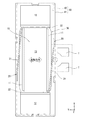
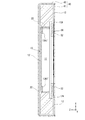
- the linear vibration motor 1 repels a long movable element 10 and the movable element 10 in a short direction (Y direction according to the illustrated example) perpendicular to the longitudinal direction (X direction according to the illustrated example). It includes elastic members 20 and 20 to be supported, a coil 30 that reciprocates the movable element 10 in the short direction by a magnetic action during energization, and a base body 40 to which the coil 30 is fixed (see FIGS. 1 to 5). ).
- the mover 10 includes a pair of long magnets 11, 11, weights 12, 12 fixed to both ends in the longitudinal direction of the magnets 11, 11, and a counter coil side of the pair of magnets 11, 11. And a yoke 13 fixed to the surface in the longitudinal direction and supported by the elastic members 20 and 20 so as to vibrate in the short direction.
- Each magnet 11 is formed in a long rectangular parallelepiped shape, and one of the directions orthogonal to the surface of the coil 30 (Z direction in the illustrated example) is an N pole and the other is an S pole.
- the pair of magnets 11 and 11 are provided substantially in parallel with a gap S therebetween.
- One magnet 11 has a magnetic pole opposite to the other magnet 11.
- the pair of magnets 11 and 11 are integrally fixed by a yoke 13.
- the yoke 13 is formed in a long shape covering the side opposite to the coil of the pair of magnets 11 and 11 and has projecting pieces 13A and 13A projecting toward the coil 30 on both ends in the longitudinal direction.
- the yoke 13 is formed in a substantially concave cross section by bending a substantially rectangular plate made of a magnetic metal material.
- Each protrusion 13A is bonded to the ends of the pair of magnets 11 and 11 via an adhesive.
- This protruding piece portion 13A has a fitting piece portion 13A1 closer to the center in the width direction (Y direction in the illustrated example).
- the fitting piece 13A1 enters and fits between the pair of magnets 11 and 11, so that the distance between the pair of magnets 11 and 11 is constant.
- the fitting piece 13A1 is disposed near the center of the magnet 11 in the thickness direction (Z direction in the drawing).
- the both side portions a and b with the fitting piece portion 13A1 in between are continuous by the base side portion c of the fitting piece portion 13A1, The parallelism of both side portions a and b and the perpendicularity to the main body surface d can be maintained with high accuracy.
- the elastic member 20 is formed by bending a metal long plate that can be elastically bent. In the illustrated example, it is formed in a substantially L shape. If it demonstrates in detail, this elastic member 20 is provided with the one piece part 21 in alignment with the end surface of the transversal direction of a pair of magnets 11 and 11, and the other piece part 22 substantially orthogonal to the one piece part 21. FIG. The short-side end surface 11B of the magnet 11 and the side wall of the base body 40 (cover portion 42) directly face each other, and the one piece portion 21 extends therebetween. The one piece portion 21 is supported by the base body 40 which is an immobile part.
- the other piece portion 22 is sandwiched and fixed between each magnet 11 (specifically, the outer surface of the protruding piece portion 13A) and the weight body 12.
- welding is applied to the fixing means. That is, the other piece 22 of the elastic member 20 is welded and fixed to the protruding piece 13 ⁇ / b> A of the yoke 13, and the weight body 12 is fixed to the other piece 22 by welding. According to this fixing structure, it is possible to prevent the connection portion between the elastic member 20 and the mover 10 from being damaged by vibration or the like.
- the one piece portion 21 of the elastic member 20 is provided with a constricted portion 21A near the center in the longitudinal direction so as to reduce the dimension in the thickness direction of the mover 10.
- the constricted portion 21 ⁇ / b> A disperses stress applied to the connection portion between the one piece portion 21 and the base body 40, the bent shape portion between the one piece portion 21 and the other piece portion 22, and the like due to the vibration of the mover 10.
- the weights 12, 12 on both sides in the longitudinal direction are formed of a metal material (for example, tungsten) having a high specific gravity, and according to the illustrated example, have a height in the Z direction that is larger than the thickness of the pair of magnets 11, 11. And it is formed in the substantially rectangular parallelepiped shape which has the width
- Each weight 12 is disposed so as not to overlap the linear portion 31 of the coil 30 in plan view. That is, each weight body 12 extends in the longitudinal direction of the mover 10 so that one end side is overlapped with the connection portion 32 of the coil 30 and the other end side extends outside the coil 30 (see FIG. 4).
- mover 10 is provided in the corner
- the notch 12 ⁇ / b> A is formed so as to leave a predetermined gap with respect to the end surface and the surface on the end side in the longitudinal direction of the coil 30. That is, as shown in FIG. 3, the weight body 12 is provided with a substantially inverted L-shaped cross section with the notch 12 ⁇ / b> A close to the end surface in the Z direction and the end surface in the X direction at the connection portion 32. According to this configuration, the weight body 12 can be disposed without hindering the reciprocation of the mover 10 by effectively using the limited space in the base body 40.
- the coil 30 is an air-core coil that does not include a core material, is wound in a long flat shape, and is provided substantially parallel to the surface of the pair of magnets 11, 11 on the side opposite to the yoke 13.
- This coil 30 has two linear portions 31, 31 along the longitudinal direction of the pair of magnets 11, 11, and connection portions 32, 32 that connect both ends of the linear portions 31, 31, respectively.
- Each linear portion 31 is a portion extending substantially linearly along the longitudinal direction of the pair of magnets 11 and 11.
- the longitudinal dimension L1 of the linear portion 31 is substantially the same as the longitudinal dimension of the hollow portion on the center side of the coil 30.
- the two linear portions 31 and 31 are positioned along the pair of magnets 11 and 11, respectively.
- the dimension L1 of each linear portion 31 is set slightly shorter than the entire length of the magnet 11.
- each magnet 11 is provided so that it may straddle each linear part 31 in a longitudinal direction in planar view. That is, the end of each magnet 11 in the longitudinal direction is located in the connection portion 32 of the coil 30 (see FIG. 4). According to this arrangement, the magnetic field generated in the linear portion 31 when energized can be effectively applied to each magnet portion, and is not easily affected by the dimensional error in the longitudinal direction.
- the width W1 of the coil 30 is set wider than the width in the same direction of the pair of magnets 11, 11, and the short direction of the pair of magnets 11, 11 is
- the end faces 11B and 11B are respectively located within the width W3 of the opposing linear portions 31.
- the width W2 between the two linear portions 31 and 31 is set to be larger than the gap S between the pair of magnets 11 and 11, and the inner edge portions 11A and 11A between the pair of magnets 11 and 11 have a width W2.
- the linear vibration motor 1 maintains a substantially constant area where the pair of magnets 11 and 11 and the coil 30 overlap in a plan view even when the mover 10 is moved in the short direction by energization. To get the driving force.
- the base body 40 includes a substrate portion 41 that supports and fixes the coil 30, and a cover portion 42 that covers the periphery of the mover 10 and the side opposite to the coil, and is configured in a long shape along the coil 30 and the mover 10.
- the substrate portion 41 is formed in a substantially long rectangular plate shape, and terminals T and T are projected from the long side portion thereof.
- the terminals T and T are connected to both ends of the coil 30, respectively.
- a drive composed of an alternating current or a pulse current having a resonance frequency (natural frequency) determined by the mass of the mover 10 and the elastic coefficient of the elastic member 20. A signal is supplied.
- the cover portion 42 is formed in a substantially rectangular box shape having an opening on the substrate portion 41 side, and is connected and fixed to the peripheral side of the substrate portion 41.
- the cover portion 42 is fixed to the inner surface of the side wall at both ends in the short direction by welding the distal end side of the one piece portion 21 of the elastic member 20 by welding.
- a pair of magnets 11, 11 are provided along the longitudinal direction of the long coil 30, and weight bodies 12, 12 are fixed to both ends of the pair of magnets 11, 11. Therefore, for example, a pair of magnets 11 and 11 are driven to reciprocate from the coil 30 in comparison with a configuration in which a plurality of coils and a pair of movers are arranged in a long shape and the movers are reciprocated in the arrangement direction. Therefore, it is possible to secure a wide effective area for receiving the magnetic action (in other words, an area where the pair of magnets 11 and 11 and the coil 30 overlap in plan view). Therefore, the magnetic characteristics and rising characteristics between the coil 30 and the pair of magnets 11 and 11 can be improved, and the responsiveness when energized can be improved.
- connection portion 32 of the coil 30 does not contribute to driving the movable element 10 in the short direction
- the weight body 12 is disposed so as to partially overlap the connection portion 32.
- the overall area in plan view can be reduced, and the entire linear vibration motor 1 can be reduced in size.
- FIG. 7 illustrates a portable information terminal 100 as a touch operation panel 50 (touch input device) including the linear vibration motor 1 according to the embodiment of the present invention and an electronic device equipped with the touch operation panel 50.
- the portable information terminal 100 is configured to vibrate the linear vibration motor 1 in response to a touch operation on the touch operation panel 50 (including a touch display), and has good responsiveness.
- the portable information terminal 100 pursuing high portability or design can be obtained by making the linear vibration motor 1 thinner and smaller.
- the linear vibration motor 1 has a compact shape in which each part is accommodated in a rectangular parallelepiped base 40 with a reduced height, the linear vibration motor 1 can be efficiently installed in the thinned portable information terminal 100.
- the linear vibration motor 1 can be mounted on an electronic device that does not include the touch operation panel 50.
- the fitting piece portion 13A1 of the yoke 13 is arranged near the center in the thickness direction (Z direction in the drawing).
- FIG. 6 it is possible to employ a configuration having a fitting piece portion 13A1 ′ having a folded shape.
- a linear vibration motor 2 shown in FIG. 6 is obtained by replacing the above-described linear vibration motor 1 with a yoke 13 'by a yoke 13'.
- the yoke 13 ' is a fitting piece portion instead of the fitting piece portion 13A1. 13A1 ′.
- This linear vibration motor 2 can also improve responsiveness by improving magnetic characteristics and rising characteristics.
- mover 10 was supported by the leaf
Landscapes
- Engineering & Computer Science (AREA)
- Power Engineering (AREA)
- Physics & Mathematics (AREA)
- Electromagnetism (AREA)
- Mechanical Engineering (AREA)
- Apparatuses For Generation Of Mechanical Vibrations (AREA)
- Reciprocating, Oscillating Or Vibrating Motors (AREA)
Abstract
L'invention concerne un moteur à vibration linéaire ayant une structure nécessitant moins d'espace et ayant également une bonne réactivité. Ce moteur à vibration linéaire est caractérisé en ce qu'il comprend : un dispositif de déplacement (10) ayant des poids (12) fixés sur le côté d'extrémité longitudinale d'une paire d'aimants longs (11, 11) ; une bobine (30) présentant une forme longue dans la direction longitudinale de la paire d'aimants (11, 11) et entraînant et déplaçant en va-et-vient le dispositif de déplacement (10) dans la direction transversale par une action magnétique produite par la conduction de l'électricité ; une base (40) à laquelle est fixée la bobine (30) ; et un élément élastique (20) déformé élastiquement par le mouvement de va-et-vient de l'élément mobile (10).
Priority Applications (2)
| Application Number | Priority Date | Filing Date | Title |
|---|---|---|---|
| US16/343,121 US20190314860A1 (en) | 2016-10-31 | 2017-10-10 | Linear vibration motor |
| CN201780066087.4A CN109891727A (zh) | 2016-10-31 | 2017-10-10 | 直线振动电机 |
Applications Claiming Priority (2)
| Application Number | Priority Date | Filing Date | Title |
|---|---|---|---|
| JP2016212971A JP6803722B2 (ja) | 2016-10-31 | 2016-10-31 | リニア振動モータ |
| JP2016-212971 | 2016-10-31 |
Publications (1)
| Publication Number | Publication Date |
|---|---|
| WO2018079251A1 true WO2018079251A1 (fr) | 2018-05-03 |
Family
ID=62023551
Family Applications (1)
| Application Number | Title | Priority Date | Filing Date |
|---|---|---|---|
| PCT/JP2017/036696 Ceased WO2018079251A1 (fr) | 2016-10-31 | 2017-10-10 | Moteur à vibration linéaire |
Country Status (4)
| Country | Link |
|---|---|
| US (1) | US20190314860A1 (fr) |
| JP (1) | JP6803722B2 (fr) |
| CN (1) | CN109891727A (fr) |
| WO (1) | WO2018079251A1 (fr) |
Cited By (3)
| Publication number | Priority date | Publication date | Assignee | Title |
|---|---|---|---|---|
| JP2020022349A (ja) * | 2018-08-03 | 2020-02-06 | エーエーシーアコースティックテクノロジーズ(シンセン)カンパニーリミテッドAAC Acoustic Technologies(Shenzhen)Co.,Ltd | 振動モータ |
| CN111756210A (zh) * | 2019-03-28 | 2020-10-09 | 日本电产三协株式会社 | 致动器 |
| WO2021115585A1 (fr) | 2019-12-11 | 2021-06-17 | Lofelt Gmbh | Actionneur à vibration linéaire ayant une bobine et un aimant mobiles |
Families Citing this family (7)
| Publication number | Priority date | Publication date | Assignee | Title |
|---|---|---|---|---|
| JPWO2021106741A1 (fr) * | 2019-11-29 | 2021-06-03 | ||
| CN214674820U (zh) * | 2020-12-22 | 2021-11-09 | 瑞声光电科技(常州)有限公司 | 一种振动马达 |
| CN214544062U (zh) * | 2020-12-25 | 2021-10-29 | 瑞声光电科技(常州)有限公司 | 一种振动马达 |
| CN214544065U (zh) * | 2020-12-25 | 2021-10-29 | 瑞声光电科技(常州)有限公司 | 一种振动马达 |
| JP7650181B2 (ja) * | 2021-04-02 | 2025-03-24 | ニデックインスツルメンツ株式会社 | アクチュエータ |
| JP7501554B2 (ja) * | 2022-02-28 | 2024-06-18 | セイコーエプソン株式会社 | 振動発生装置、振動低減装置及び電子機器 |
| JP7845966B2 (ja) * | 2022-08-30 | 2026-04-14 | ニデックインスツルメンツ株式会社 | アクチュエータ |
Citations (3)
| Publication number | Priority date | Publication date | Assignee | Title |
|---|---|---|---|---|
| US20110241451A1 (en) * | 2010-04-05 | 2011-10-06 | Lg Innotek Co., Ltd. | Linear Vibrator |
| JP2013163172A (ja) * | 2012-02-13 | 2013-08-22 | Minebea Co Ltd | 振動発生器 |
| WO2016167299A1 (fr) * | 2015-04-17 | 2016-10-20 | 日本電産コパル株式会社 | Moteur à vibration linéaire |
Family Cites Families (5)
| Publication number | Priority date | Publication date | Assignee | Title |
|---|---|---|---|---|
| US8618701B2 (en) * | 2008-10-31 | 2013-12-31 | Mitsumi Electric Co., Ltd. | Actuator and electric toothbrush using actuator |
| WO2010103929A1 (fr) * | 2009-03-10 | 2010-09-16 | 三洋電機株式会社 | Moteur à vibrations et appareil portable |
| US9590463B2 (en) * | 2011-09-22 | 2017-03-07 | Minebea Co., Ltd. | Vibration generator moving vibrator by magnetic field generated by coil and holder used in vibration-generator |
| CN204810113U (zh) * | 2015-07-16 | 2015-11-25 | 瑞声光电科技(常州)有限公司 | 振动电机 |
| CN205544862U (zh) * | 2015-11-10 | 2016-08-31 | 瑞声光电科技(常州)有限公司 | 振动电机 |
-
2016
- 2016-10-31 JP JP2016212971A patent/JP6803722B2/ja not_active Expired - Fee Related
-
2017
- 2017-10-10 WO PCT/JP2017/036696 patent/WO2018079251A1/fr not_active Ceased
- 2017-10-10 US US16/343,121 patent/US20190314860A1/en not_active Abandoned
- 2017-10-10 CN CN201780066087.4A patent/CN109891727A/zh active Pending
Patent Citations (3)
| Publication number | Priority date | Publication date | Assignee | Title |
|---|---|---|---|---|
| US20110241451A1 (en) * | 2010-04-05 | 2011-10-06 | Lg Innotek Co., Ltd. | Linear Vibrator |
| JP2013163172A (ja) * | 2012-02-13 | 2013-08-22 | Minebea Co Ltd | 振動発生器 |
| WO2016167299A1 (fr) * | 2015-04-17 | 2016-10-20 | 日本電産コパル株式会社 | Moteur à vibration linéaire |
Cited By (7)
| Publication number | Priority date | Publication date | Assignee | Title |
|---|---|---|---|---|
| JP2020022349A (ja) * | 2018-08-03 | 2020-02-06 | エーエーシーアコースティックテクノロジーズ(シンセン)カンパニーリミテッドAAC Acoustic Technologies(Shenzhen)Co.,Ltd | 振動モータ |
| CN111756210A (zh) * | 2019-03-28 | 2020-10-09 | 日本电产三协株式会社 | 致动器 |
| CN111756210B (zh) * | 2019-03-28 | 2023-03-21 | 日本电产三协株式会社 | 致动器 |
| WO2021115585A1 (fr) | 2019-12-11 | 2021-06-17 | Lofelt Gmbh | Actionneur à vibration linéaire ayant une bobine et un aimant mobiles |
| WO2021116385A1 (fr) | 2019-12-11 | 2021-06-17 | Lofelt Gmbh | Actionneur de vibration linéaire ayant une bobine mobile et un aimant mobile |
| US20230012628A1 (en) * | 2019-12-11 | 2023-01-19 | Lofelt Gmbh | Linear vibration actuator having moving coil and moving magnet |
| US11784548B2 (en) | 2019-12-11 | 2023-10-10 | Meta Platforms, Inc. | Vibrating actuator with two resonant frequencies and two moving parts |
Also Published As
| Publication number | Publication date |
|---|---|
| JP2018074781A (ja) | 2018-05-10 |
| CN109891727A (zh) | 2019-06-14 |
| JP6803722B2 (ja) | 2020-12-23 |
| US20190314860A1 (en) | 2019-10-17 |
Similar Documents
| Publication | Publication Date | Title |
|---|---|---|
| WO2018079251A1 (fr) | Moteur à vibration linéaire | |
| JP7677704B2 (ja) | 振動アクチュエータ及び振動呈示装置 | |
| CN106471719B (zh) | 致动器 | |
| JP6396129B2 (ja) | リニア振動モータの製造方法 | |
| CN107107111B (zh) | 振动致动器 | |
| JP6591248B2 (ja) | リニア振動モータ | |
| WO2019151232A1 (fr) | Actionneur à vibration linéaire | |
| JP4487650B2 (ja) | 振動型リニアアクチュエータ及びこれを用いた往復式電気かみそり | |
| JP2004023909A (ja) | 振動型リニアアクチュエータ | |
| CN110098714B (zh) | 致动器及其制造方法 | |
| WO2019102704A1 (fr) | Moteur à vibration linéaire et appareil électronique | |
| CN107107112A (zh) | 线性振动马达 | |
| JP6971714B2 (ja) | リニア振動モータ及び電子機器 | |
| JP6444035B2 (ja) | 電磁振動アクチュエータ | |
| CN117858768A (zh) | 振动致动器 | |
| JP2019013087A (ja) | アクチュエータ | |
| JP5260927B2 (ja) | 振動型リニアアクチュエータ | |
| JP6378125B2 (ja) | リニア振動モータ | |
| CN110098711B (zh) | 致动器 | |
| WO2018008280A1 (fr) | Moteur à vibration linéaire | |
| JP2017212793A (ja) | リニア振動モータ | |
| JP2020184841A (ja) | 振動アクチュエータ及び触覚デバイス | |
| CN110098713B (zh) | 致动器 | |
| JP2019009872A (ja) | リニア振動モータ及び電子機器 | |
| JP6479557B2 (ja) | リニア振動モータ |
Legal Events
| Date | Code | Title | Description |
|---|---|---|---|
| 121 | Ep: the epo has been informed by wipo that ep was designated in this application |
Ref document number: 17866105 Country of ref document: EP Kind code of ref document: A1 |
|
| NENP | Non-entry into the national phase |
Ref country code: DE |
|
| 122 | Ep: pct application non-entry in european phase |
Ref document number: 17866105 Country of ref document: EP Kind code of ref document: A1 |