WO2018079372A1 - Dispositif de capture d'image, système de capture d'image, corps mobile et procédé de capture d'image - Google Patents
Dispositif de capture d'image, système de capture d'image, corps mobile et procédé de capture d'image Download PDFInfo
- Publication number
- WO2018079372A1 WO2018079372A1 PCT/JP2017/037678 JP2017037678W WO2018079372A1 WO 2018079372 A1 WO2018079372 A1 WO 2018079372A1 JP 2017037678 W JP2017037678 W JP 2017037678W WO 2018079372 A1 WO2018079372 A1 WO 2018079372A1
- Authority
- WO
- WIPO (PCT)
- Prior art keywords
- infrared ray
- image
- infrared
- control unit
- light source
- Prior art date
- Legal status (The legal status is an assumption and is not a legal conclusion. Google has not performed a legal analysis and makes no representation as to the accuracy of the status listed.)
- Ceased
Links
Images


Classifications
-
- G—PHYSICS
- G03—PHOTOGRAPHY; CINEMATOGRAPHY; ANALOGOUS TECHNIQUES USING WAVES OTHER THAN OPTICAL WAVES; ELECTROGRAPHY; HOLOGRAPHY
- G03B—APPARATUS OR ARRANGEMENTS FOR TAKING PHOTOGRAPHS OR FOR PROJECTING OR VIEWING THEM; APPARATUS OR ARRANGEMENTS EMPLOYING ANALOGOUS TECHNIQUES USING WAVES OTHER THAN OPTICAL WAVES; ACCESSORIES THEREFOR
- G03B15/00—Special procedures for taking photographs; Apparatus therefor
- G03B15/02—Illuminating scene
- G03B15/03—Combinations of cameras with lighting apparatus; Flash units
- G03B15/05—Combinations of cameras with electronic flash apparatus; Electronic flash units
-
- H—ELECTRICITY
- H04—ELECTRIC COMMUNICATION TECHNIQUE
- H04N—PICTORIAL COMMUNICATION, e.g. TELEVISION
- H04N23/00—Cameras or camera modules comprising electronic image sensors; Control thereof
- H04N23/70—Circuitry for compensating brightness variation in the scene
- H04N23/72—Combination of two or more compensation controls
-
- G—PHYSICS
- G03—PHOTOGRAPHY; CINEMATOGRAPHY; ANALOGOUS TECHNIQUES USING WAVES OTHER THAN OPTICAL WAVES; ELECTROGRAPHY; HOLOGRAPHY
- G03B—APPARATUS OR ARRANGEMENTS FOR TAKING PHOTOGRAPHS OR FOR PROJECTING OR VIEWING THEM; APPARATUS OR ARRANGEMENTS EMPLOYING ANALOGOUS TECHNIQUES USING WAVES OTHER THAN OPTICAL WAVES; ACCESSORIES THEREFOR
- G03B15/00—Special procedures for taking photographs; Apparatus therefor
-
- G—PHYSICS
- G03—PHOTOGRAPHY; CINEMATOGRAPHY; ANALOGOUS TECHNIQUES USING WAVES OTHER THAN OPTICAL WAVES; ELECTROGRAPHY; HOLOGRAPHY
- G03B—APPARATUS OR ARRANGEMENTS FOR TAKING PHOTOGRAPHS OR FOR PROJECTING OR VIEWING THEM; APPARATUS OR ARRANGEMENTS EMPLOYING ANALOGOUS TECHNIQUES USING WAVES OTHER THAN OPTICAL WAVES; ACCESSORIES THEREFOR
- G03B15/00—Special procedures for taking photographs; Apparatus therefor
- G03B15/02—Illuminating scene
-
- G—PHYSICS
- G03—PHOTOGRAPHY; CINEMATOGRAPHY; ANALOGOUS TECHNIQUES USING WAVES OTHER THAN OPTICAL WAVES; ELECTROGRAPHY; HOLOGRAPHY
- G03B—APPARATUS OR ARRANGEMENTS FOR TAKING PHOTOGRAPHS OR FOR PROJECTING OR VIEWING THEM; APPARATUS OR ARRANGEMENTS EMPLOYING ANALOGOUS TECHNIQUES USING WAVES OTHER THAN OPTICAL WAVES; ACCESSORIES THEREFOR
- G03B17/00—Details of cameras or camera bodies; Accessories therefor
- G03B17/02—Bodies
-
- G—PHYSICS
- G03—PHOTOGRAPHY; CINEMATOGRAPHY; ANALOGOUS TECHNIQUES USING WAVES OTHER THAN OPTICAL WAVES; ELECTROGRAPHY; HOLOGRAPHY
- G03B—APPARATUS OR ARRANGEMENTS FOR TAKING PHOTOGRAPHS OR FOR PROJECTING OR VIEWING THEM; APPARATUS OR ARRANGEMENTS EMPLOYING ANALOGOUS TECHNIQUES USING WAVES OTHER THAN OPTICAL WAVES; ACCESSORIES THEREFOR
- G03B7/00—Control of exposure by setting shutters, diaphragms or filters, separately or conjointly
- G03B7/08—Control effected solely on the basis of the response, to the intensity of the light received by the camera, of a built-in light-sensitive device
- G03B7/091—Digital circuits
-
- H—ELECTRICITY
- H04—ELECTRIC COMMUNICATION TECHNIQUE
- H04N—PICTORIAL COMMUNICATION, e.g. TELEVISION
- H04N23/00—Cameras or camera modules comprising electronic image sensors; Control thereof
-
- H—ELECTRICITY
- H04—ELECTRIC COMMUNICATION TECHNIQUE
- H04N—PICTORIAL COMMUNICATION, e.g. TELEVISION
- H04N23/00—Cameras or camera modules comprising electronic image sensors; Control thereof
- H04N23/10—Cameras or camera modules comprising electronic image sensors; Control thereof for generating image signals from different wavelengths
- H04N23/11—Cameras or camera modules comprising electronic image sensors; Control thereof for generating image signals from different wavelengths for generating image signals from visible and infrared light wavelengths
-
- H—ELECTRICITY
- H04—ELECTRIC COMMUNICATION TECHNIQUE
- H04N—PICTORIAL COMMUNICATION, e.g. TELEVISION
- H04N23/00—Cameras or camera modules comprising electronic image sensors; Control thereof
- H04N23/56—Cameras or camera modules comprising electronic image sensors; Control thereof provided with illuminating means
-
- H—ELECTRICITY
- H04—ELECTRIC COMMUNICATION TECHNIQUE
- H04N—PICTORIAL COMMUNICATION, e.g. TELEVISION
- H04N23/00—Cameras or camera modules comprising electronic image sensors; Control thereof
- H04N23/60—Control of cameras or camera modules
-
- H—ELECTRICITY
- H04—ELECTRIC COMMUNICATION TECHNIQUE
- H04N—PICTORIAL COMMUNICATION, e.g. TELEVISION
- H04N23/00—Cameras or camera modules comprising electronic image sensors; Control thereof
- H04N23/70—Circuitry for compensating brightness variation in the scene
- H04N23/71—Circuitry for evaluating the brightness variation
-
- H—ELECTRICITY
- H04—ELECTRIC COMMUNICATION TECHNIQUE
- H04N—PICTORIAL COMMUNICATION, e.g. TELEVISION
- H04N23/00—Cameras or camera modules comprising electronic image sensors; Control thereof
- H04N23/70—Circuitry for compensating brightness variation in the scene
- H04N23/74—Circuitry for compensating brightness variation in the scene by influencing the scene brightness using illuminating means
-
- H—ELECTRICITY
- H04—ELECTRIC COMMUNICATION TECHNIQUE
- H04N—PICTORIAL COMMUNICATION, e.g. TELEVISION
- H04N23/00—Cameras or camera modules comprising electronic image sensors; Control thereof
- H04N23/95—Computational photography systems, e.g. light-field imaging systems
- H04N23/951—Computational photography systems, e.g. light-field imaging systems by using two or more images to influence resolution, frame rate or aspect ratio
-
- H—ELECTRICITY
- H04—ELECTRIC COMMUNICATION TECHNIQUE
- H04N—PICTORIAL COMMUNICATION, e.g. TELEVISION
- H04N5/00—Details of television systems
- H04N5/222—Studio circuitry; Studio devices; Studio equipment
- H04N5/262—Studio circuits, e.g. for mixing, switching-over, change of character of image, other special effects ; Cameras specially adapted for the electronic generation of special effects
- H04N5/265—Mixing
-
- H—ELECTRICITY
- H04—ELECTRIC COMMUNICATION TECHNIQUE
- H04N—PICTORIAL COMMUNICATION, e.g. TELEVISION
- H04N7/00—Television systems
- H04N7/18—Closed-circuit television [CCTV] systems, i.e. systems in which the video signal is not broadcast
-
- H—ELECTRICITY
- H04—ELECTRIC COMMUNICATION TECHNIQUE
- H04N—PICTORIAL COMMUNICATION, e.g. TELEVISION
- H04N7/00—Television systems
- H04N7/18—Closed-circuit television [CCTV] systems, i.e. systems in which the video signal is not broadcast
- H04N7/183—Closed-circuit television [CCTV] systems, i.e. systems in which the video signal is not broadcast for receiving images from a single remote source
-
- H—ELECTRICITY
- H04—ELECTRIC COMMUNICATION TECHNIQUE
- H04N—PICTORIAL COMMUNICATION, e.g. TELEVISION
- H04N9/00—Details of colour television systems
- H04N9/77—Circuits for processing the brightness signal and the chrominance signal relative to each other, e.g. adjusting the phase of the brightness signal relative to the colour signal, correcting differential gain or differential phase
-
- B—PERFORMING OPERATIONS; TRANSPORTING
- B60—VEHICLES IN GENERAL
- B60R—VEHICLES, VEHICLE FITTINGS, OR VEHICLE PARTS, NOT OTHERWISE PROVIDED FOR
- B60R2300/00—Details of viewing arrangements using cameras and displays, specially adapted for use in a vehicle
- B60R2300/10—Details of viewing arrangements using cameras and displays, specially adapted for use in a vehicle characterised by the type of camera system used
- B60R2300/103—Details of viewing arrangements using cameras and displays, specially adapted for use in a vehicle characterised by the type of camera system used using camera systems provided with artificial illumination device, e.g. IR light source
Definitions
- the present disclosure relates to an imaging apparatus, an imaging system, a moving object, and an imaging method.
- Patent Document 1 discloses an imaging device for reproducing the color of a subject in an environment with little visible light.
- the imaging device described in Patent Document 1 sequentially turns on infrared light having different wavelengths respectively associated with red, blue, and green colors.
- the imaging device generates a composite image based on an image captured while each infrared light is lit.
- the present disclosure provides an imaging system, a moving body, and an imaging method that can generate an image including a color with high brightness contrast even in a dark environment with a simple configuration.
- the imaging device includes an imaging element and a control unit.
- the control unit acquires an infrared ray image generated by the imaging device when the infrared ray is higher than a predetermined amount of light.
- the control unit acquires a normal image generated by the imaging device when the infrared ray is lower than a predetermined amount of light.
- the control unit generates a composite image based on the infrared ray image and the normal image.
- the imaging system of the present disclosure includes an infrared light source and an imaging device.
- the infrared light source emits infrared light.
- the imaging device includes an imaging element and a control unit.
- the control unit acquires an infrared ray image generated by the imaging device when the infrared ray is higher than a predetermined amount of light.
- the control unit acquires a normal image generated by the imaging device when the infrared ray is lower than a predetermined amount of light.
- the control unit generates a composite image based on the infrared ray image and the normal image.
- the moving body of the present disclosure includes an imaging system.
- the imaging system includes an infrared light source and an imaging device.
- the infrared light source emits infrared light.
- the imaging apparatus includes an imaging element and a control unit.
- the control unit acquires an infrared ray image generated by the imaging device when the infrared ray is higher than a predetermined amount of light.
- the control unit acquires a normal image generated by the imaging element when the infrared ray is lower than a predetermined amount of light.
- the control unit generates a composite image based on the infrared ray image and the normal image.
- the imaging method of the present disclosure is an imaging method of an imaging device.
- the imaging device acquires an infrared ray image captured by the imaging element when the infrared ray is higher than a predetermined amount of light.
- the imaging device acquires a normal image captured by the imaging element when the infrared ray is lower than a predetermined amount of light.
- the imaging device generates a composite image based on the infrared ray image and the normal image.
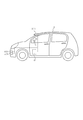
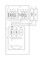
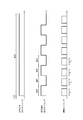
- FIG. 1 shows the example of the mobile body carrying the imaging system which concerns on this embodiment. It is a functional block diagram which shows schematic structure of the imaging system which concerns on this embodiment. It is a timing chart which shows an example of the timing of operation
- an imaging system 1 including an imaging device 3 according to this embodiment can be attached to a moving body 2.
- the imaging device 3 is arranged so as to capture a predetermined direction when viewed from the moving body 2.
- the infrared light source 4 and the white light source 5 are attached to the imaging range of the imaging device 3 so as to be able to irradiate infrared light and white light, respectively.
- “Moving object” in the present disclosure includes a vehicle, a ship, and an aircraft.
- Vehicle in the present disclosure includes, but is not limited to, automobiles, railway vehicles, industrial vehicles, and daily life vehicles.
- the vehicle may include an airplane traveling on a runway.
- the automobile includes, but is not limited to, a passenger car, a truck, a bus, a two-wheeled vehicle, a trolley bus, and the like, and may include other vehicles that travel on the road.
- Rail vehicles include, but are not limited to, locomotives, freight cars, passenger cars, trams, guided railroads, ropeways, cable cars, linear motor cars, and monorails.
- a tracked vehicle may include other vehicles that travel along the track.
- Industrial vehicles include industrial vehicles for agriculture and construction.
- Industrial vehicles include but are not limited to forklifts and golf carts.
- Industrial vehicles for agriculture include, but are not limited to, tractors, tillers, transplanters, binders, combines, and lawn mowers.
- Industrial vehicles for construction include, but are not limited to, bulldozers, scrapers, excavators, crane trucks, dump trucks, and road rollers.
- Living vehicles include, but are not limited to, bicycles, wheelchairs, baby carriages, wheelbarrows, and electric standing and riding motorcycles.
- Vehicle power engines include, but are not limited to, internal combustion engines including diesel engines, gasoline engines, and hydrogen engines, and electrical engines including motors. Vehicles include those that travel by human power.
- the vehicle classification is not limited to the above.
- the automobile may include an industrial vehicle capable of traveling on a road, and the same vehicle may be included in a plurality of classifications.
- the imaging system 1 includes an imaging device 3, an infrared light source 4, and a white light source 5.
- the imaging device 3 includes an optical system 6, an imaging element 7, a communication unit 8, a control unit 9, and a memory 10.
- the optical system 6 has at least one optical element such as a lens and a diaphragm according to desired optical characteristics.
- the optical system 6 is designed to satisfy desired optical characteristics such as a focal length and a focal depth.
- the optical system 6 forms an image of the subject on the image sensor 7.
- the image sensor 7 is arranged so that the light receiving surface of the image sensor 7 is perpendicular to the optical axis of the optical system 6. Further, the image sensor 7 is disposed so as to intersect the optical axis of the optical system 6 at the approximate center of the light receiving surface.
- the image sensor 7 captures an image of a subject formed on the light receiving surface via the optical system 6 and outputs an image signal corresponding to the captured image.
- the imaging device 7 for example, a CCD (Charge-Coupled Device) or a CMOS (Complementary Metal-Oxide Semiconductor) image sensor can be used.
- the imaging device 7 has sensitivity to at least visible light and near infrared light, and converts visible light and near infrared light received by the light receiving surface into an image signal.
- the image sensor 7 is sensitive to infrared light having a wavelength longer than the wavelength of near infrared light, infrared light having a wavelength longer than the wavelength of near infrared light is absorbed or reflected on the subject side of the image sensor 7.
- a filter may be arranged.
- the communication unit 8 transmits a control signal output by the control unit 9 to the infrared light source 4.
- the control signal is a signal for controlling the infrared light source 4 so that the infrared ray becomes higher or lower than the predetermined amount of light.
- the infrared ray becomes higher than a predetermined amount of light.
- the infrared ray becomes lower than the predetermined amount of light by the extinction of the infrared ray.
- the communication unit 8 can transmit an image signal to the outside of the imaging device 3. Thereby, the communication unit 8 can transmit the composite image generated by the control unit 9 to the outside of the imaging device 3.
- the composite image is external to the imaging device 3, for example, the display device 11 mounted on the mobile body 2, the ECU (Electric Control Unit) 12 of the mobile body 2, or the mobile body 2 connected via a wireless communication network. To an external device.
- the control unit 9 is, for example, an ISP (Image Signal Processor) that acquires and processes an image captured by the image sensor 7.
- ISP Image Signal Processor
- the memory 10 stores an image acquired from the image sensor 7 by the control unit 9.
- the memory 10 stores an image processed by the control unit 9.
- the infrared light source 4 emits infrared rays.
- the irradiation range of the infrared light source 4 is a part of the irradiation range of the white light source 5 described later.
- the infrared light source 4 includes a communication unit 13, a control unit 14, and a light emitting element 17.
- the communication unit 13 transmits and receives signals to and from an external device. Further, the control unit 14 controls the light emitting element 17 so that the infrared ray is turned on or off. The light emitting element 17 turns on and off the infrared ray based on the control of the control unit 14. The light emitting element 17 is attached to the moving body 2 so that at least a part of the imaging range of the imaging element 7 can be irradiated with infrared light.
- the white light source 5 emits white light.
- the white light source 5 includes a communication unit 15, a control unit 16, and a light emitting element 18.
- the communication unit 15 transmits a signal with an external device.
- the control unit 16 controls the light emitting element 18 so that white light is turned on or off.
- the light emitting element 18 turns on or off the white light based on the control of the control unit 16.
- the light emitting element 17 is attached to the moving body 2 so that at least a part of the imaging range of the imaging element 7 can be irradiated with white light.
- the white light source 5 is attached to the moving body 2.
- the white light source 5 can be a so-called headlight.
- the white light source 5 can switch between two irradiation ranges that emit white light.
- the two irradiation ranges differ at least in the vertical direction of the road surface.
- the irradiation range below vertically corresponds to the “first irradiation range”
- the irradiation range above vertically corresponds to the “second irradiation range” including the range vertically above the first irradiation range.
- the white light source 5 irradiates the irradiation range vertically below, the white light emitted from the white light source 5 is a so-called low beam.
- the white light source 5 irradiates the irradiation range vertically above, the white light emitted from the white light source 5 is a so-called high beam.
- the imaging device 3 will be described in detail.
- the image sensor 7 captures an object in a direction in which the infrared light source 4 can irradiate infrared rays and the white light source 5 can irradiate white light, and generates an image.
- the control unit 9 causes the image sensor 7 to perform imaging every frame imaging time. As a result, the image sensor 7 captures the subject at a frame imaging time corresponding to a preset frame rate and generates a one-frame image.
- control unit 9 transmits a control signal synchronized with the frame imaging time to the infrared light source 4 via the communication unit 8. Specifically, as illustrated in FIG. 3, the control unit 9 transmits a control signal so that the infrared light source 4 is irradiated with infrared rays in the period P 1 . Further, the control unit 9 causes the image sensor 7 to generate an image during the period P 1 . In addition, the control unit 9 transmits a control signal so that the infrared light source 4 stops the irradiation of infrared rays during the frame imaging time (period P 2 ) next to the frame imaging time corresponding to the period P 1 .
- the period P 1 corresponds to the “first period”, and the period P 2 corresponds to the “second period”.
- the control unit 9 transmits a control signal so that the infrared light source 4 is irradiated with infrared rays during the next frame imaging time (period P 1 ).
- the control unit 9 provides a control signal for causing the infrared ray to repeatedly turn on and off in response to the frame imaging times of the period P 1 and the period P 2 being alternately repeated. Send to repeatedly.
- the communication unit 13 of the infrared light source 4 receives the control signal transmitted from the imaging device 3.
- the control unit 14 of the infrared light source 4 turns on or off the infrared ray based on the control signal received by the communication unit 13.
- the infrared ray is repeatedly turned on and off in synchronization with the frame imaging time corresponding to the frame rate of the imaging device 3. Specifically, the infrared ray is turned on at one frame imaging time and turned off at the next frame imaging time. Then, such turning on and off of the infrared ray is repeatedly executed.
- control unit 9 always transmits a control signal for lighting white light to the white light source 5 via the communication unit 8 during the imaging processing according to the present embodiment.
- the communication unit 15 of the white light source 5 receives the control signal transmitted from the imaging device 3.
- the control unit 16 of the white light source 5 turns on white light based on the control signal received by the communication unit 15. Thereby, as shown in FIG. 3, white light always lights up.
- the control unit 9 acquires an image captured by the image sensor 7 when the infrared ray is turned on or off.
- An image when the infrared ray is turned on corresponds to an “infrared ray image”, and an image when the infrared ray is turned off corresponds to a “normal image”.
- the control unit 9 generates a composite image based on the infrared ray image acquired from the image sensor 7 and the normal image. Specifically, the control unit 9 calculates the intensity of the luminance signal Y from the pixel signal of each pixel constituting the infrared ray image. Further, the control unit 9 calculates the intensities of the color difference signals Cb and Cr from the pixel signal of each pixel constituting the normal image. Then, the control unit 9 generates a color signal using the calculated luminance signal Y of each pixel and the color difference signals Cb and Cr of each corresponding pixel.
- the control unit 9 may perform gain correction on the color difference signals Cb and Cr when generating the composite image. Specifically, the control unit 9 performs gain correction based on the intensity of the luminance signal Y and the intensity of the color difference signals Cb and Cr. For example, the control unit 9 calculates a value based on the intensity of the luminance signal Y of all pixels constituting the infrared ray image. The value based on the intensity of the luminance signal Y of all the pixels is, for example, a representative value Yr (statistic value such as an average value, median value, maximum value) of the luminance signal Y. Further, the control unit 9 calculates a value based on the color difference signals Cb and Cr of all the pixels constituting the normal image.
- the values based on the color difference signals Cb and Cr of all the pixels are, for example, representative values Cbr and Cr r (statistic values such as an average value, a median value, and a maximum value) of the intensity of each of the color difference signals Cb and Cr.
- control unit 9 and the average value of the representative values Cb r and Cr r, the gain to be multiplied to the color difference signals Cb and Cr of each pixel as Samata the ratio of the representative value Y r is within a predetermined range calculate.
- control unit 9 multiplies the calculated gain by the color difference signals Cb and Cr of each pixel.
- the control unit 9 generates a color signal based on the luminance signal Y of each pixel and the corrected color difference signals Cb1 and Cr1 of each corresponding pixel.
- Control unit 9 the infrared light image and the representative value Yr usually based on all the pixels constituting the image, Cb r, and was calculated Cr r, constitutes a part of the infrared light image and a normal image pixel
- the representative values Y r , Cb r , and Cr r may be calculated based on.
- the imaging device 3 starts processing when the white light source 5 starts irradiation of white light.
- the white light source 5 starts irradiating white light when receiving an operation start instruction from the user of the imaging system 1.
- the white light source 5 may start irradiation of white light by control from ECU which detected that the environment became dark with the light quantity sensor.
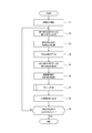
- control unit 9 causes the image sensor 7 to start executing an image (step S1). That is, the control unit 9 causes the image sensor 7 to continuously capture images according to a preset frame rate.
- control unit 9 transmits a control signal for turning on the infrared ray to the infrared light source 4 via the communication unit 8 (step S2).
- the control unit 9 acquires an infrared ray image captured when the infrared ray is turned on by the control signal in step S2, and stores it in the memory 10 (step S3).
- the control unit 9 determines the luminance signal Y of the infrared ray image stored in the memory 10 in step S3 and the corrected color difference signals Cr1 and Cb1 of the normal image captured most recently among the normal images already stored in the memory 10. Based on the above, a composite image is generated (step S4).
- control unit 9 transmits a control signal for turning off the infrared ray to the infrared light source 4 via the communication unit 8 in synchronization with the next frame imaging time (step S5).
- control unit 9 When the control signal is transmitted in step S5, the control unit 9 acquires a normal image captured when the infrared ray is turned off by the control signal in step S5, and stores it in the memory 10 (step S6).
- the control unit 9 performs gain correction on the color difference signals Cr and Cb of the normal image acquired in step S6 (step S7).
- control unit 9 calculates the representative value Yr of the intensity of the luminance signal Y of the infrared ray image acquired immediately before the normal image is acquired in step S5 and stored in the memory 10 (step S71). .
- the control unit 9 calculates representative values Crr and Cbr of the intensity of the color difference signals Cr and Cb of the normal image acquired in step S5 (step S72).
- the process of step S72 may be performed before the process of step S71.
- the control unit 9 performs gain correction on the color difference signals Cr and Cb of each pixel based on the representative value Yr and the representative values Crr and Cbr, and generates corrected color difference signals Cr1 and Cb1 (step S73). Specifically, for example, the controller 9 determines the intensity of the color difference signals Cb and Cr of each pixel so that the difference or ratio between the average value of the representative values Crr and Cbr and the representative value Yr is within a predetermined range. The gain to be multiplied may be calculated. Then, the control unit 9 multiplies the intensity of the color difference signals Cb and Cr of each pixel by a gain.
- step S 8 when the gain correction is performed in step S ⁇ b> 7, the control unit 9 is picked up most recently among the corrected color difference signals Cr ⁇ b> 1 and Cb ⁇ b> 1 of the normal image and the infrared ray image already stored in the memory 10. A composite image is generated based on the brightness signal Y of the infrared ray image (step S8).
- control unit 9 determines whether a stop instruction is input to the imaging apparatus 3 (step S9).
- step S9 If it is determined in step S9 that a stop instruction has been input, the imaging device 3 ends the process. When it is determined in step S9 that no stop instruction has been input, the imaging device 3 returns to step S2 again and transmits a control signal. Then, the control unit 9 repeats the processes of steps S2 to S9.
- the imaging device 3 generates an image based on the infrared ray image and the normal image. Specifically, the imaging device 3 generates a composite image having the luminance signal Y of the infrared ray image and the color difference signals Cb and Cr of the normal image. Infrared rays have a higher reflectance from the subject than white light even in a dark environment. Therefore, the control unit 9 can obtain a luminance signal Y having a higher intensity and a larger contrast than the normal image from the infrared ray image. Further, the control unit 9 can obtain the color difference signals Cr and Cb from the normal image.
- the imaging device 3 is an image with a low S / N ratio and high contrast based on the luminance signal Y even in a dark environment such as at night, and includes a color based on the color difference signals Cb and Cr. An image can be generated.
- the imaging device 3 performs gain correction only on the color difference signals Cb and Cr of the normal image.
- the intensity of the pixel signal is generally small, the intensity of the color difference signals Cb and Cr is relatively small, and the color of the composite image can be weak.
- the gain correction increases the intensity of the color difference signals Cb and Cr, and the color can be reproduced strongly. Since gain correction is not performed on the luminance signal Y, the entire image can be prevented from approaching white. For this reason, the imaging device 3 can generate an image having a high brightness contrast and including bright colors.
- the infrared light source 4 irradiates infrared light as a high beam.
- many drivers usually irradiate white light emitted from the white light source 5 as a low beam.
- the human eye does not sense infrared light. Therefore, the imaging device 3 can irradiate the infrared light source 4 with a high beam so that the user can detect the subject without detecting the glare.
- the white light source 5 always irradiates white light. Therefore, white light is turned off when the infrared ray is turned on, and the user does not feel uncomfortable due to the blinking of the white light when the white light is turned on when the infrared ray is turned off. There is.
- control unit 9 transmits the control signal for controlling the lighting of the infrared ray by the infrared light source 4 via the communication unit 8, but this is not restrictive.
- control unit 9 may receive a lighting state signal indicating a lighting state of an infrared ray from the infrared light source 4 via the communication unit 8.
- the lighting state signal is a signal indicating one or more of whether the infrared ray is turned on and that the infrared ray is turned off.
- the control unit 9 when the control unit 9 receives the lighting state signal indicating the lighting of the infrared ray from the infrared light source 4, the image generated by the imaging element 7 when the infrared ray is lit is used as the infrared ray image. get.
- the communication unit 8 receives a lighting state signal indicating that the infrared ray is turned off from the infrared light source 4
- the control unit 9 displays an image generated by the imaging element 7 when the infrared ray is turned off as a normal image. Get as.
- the white light source 5 stops the white light irradiation when the infrared light source 4 is irradiating infrared light, and the infrared light source 4 emits infrared light.
- White light may be emitted when irradiation is stopped.
- the turning on and off of the white light is preferably repeated at high speed so as not to be recognized by human eyes. Thereby, it can be avoided that the human being feels uncomfortable due to the continuous turn-on and turn-off.
- the control unit 9 has been to calculate the gain by using both of the representative values Cb r and Cr r, not limited.
- the control unit 9, using any of the representative value Cb r and Cr r may be calculated gain for correcting any color difference signals Cb and Cr according to the representative value.
- the method by which the control unit 9 calculates the gain is appropriately determined according to the characteristics of the composite image obtained by the user according to the application.
Landscapes
- Engineering & Computer Science (AREA)
- Multimedia (AREA)
- Signal Processing (AREA)
- Physics & Mathematics (AREA)
- General Physics & Mathematics (AREA)
- Computing Systems (AREA)
- Theoretical Computer Science (AREA)
- Studio Devices (AREA)
- Color Television Image Signal Generators (AREA)
- Transforming Light Signals Into Electric Signals (AREA)
- Camera Bodies And Camera Details Or Accessories (AREA)
Abstract
L'invention concerne un dispositif de capture d'image (3) qui comprend un élément de capture d'image (7) et une unité de commande (9). L'unité de commande (9) acquiert une image infrarouge générée par l'élément de capture d'image (7) lorsque la quantité de lumière infrarouge est supérieure à une valeur prédéterminée. L'unité de commande (9) acquiert une image normale générée par l'élément de capture d'image (7) lorsque la quantité de lumière infrarouge est inférieure à la valeur prédéterminée. L'unité de commande (9) génère une image synthétique sur la base de l'image infrarouge et de l'image normale. Par conséquent, une image qui a un contraste de luminance élevé et comprend des couleurs peut être générée même dans un environnement sombre, sans avoir à fournir une pluralité de sources de lumière infrarouge.
Priority Applications (3)
| Application Number | Priority Date | Filing Date | Title |
|---|---|---|---|
| JP2018547598A JPWO2018079372A1 (ja) | 2016-10-28 | 2017-10-18 | 撮像装置、撮像システム、移動体、及び撮像方法 |
| EP17863548.8A EP3534603B1 (fr) | 2016-10-28 | 2017-10-18 | Dispositif de capture d'image et procédé de capture d'image |
| US16/345,636 US10742890B2 (en) | 2016-10-28 | 2017-10-18 | Imaging apparatus, imaging system, moving body, and imaging method |
Applications Claiming Priority (2)
| Application Number | Priority Date | Filing Date | Title |
|---|---|---|---|
| JP2016212325 | 2016-10-28 | ||
| JP2016-212325 | 2016-10-28 |
Publications (1)
| Publication Number | Publication Date |
|---|---|
| WO2018079372A1 true WO2018079372A1 (fr) | 2018-05-03 |
Family
ID=62023425
Family Applications (1)
| Application Number | Title | Priority Date | Filing Date |
|---|---|---|---|
| PCT/JP2017/037678 Ceased WO2018079372A1 (fr) | 2016-10-28 | 2017-10-18 | Dispositif de capture d'image, système de capture d'image, corps mobile et procédé de capture d'image |
Country Status (4)
| Country | Link |
|---|---|
| US (1) | US10742890B2 (fr) |
| EP (1) | EP3534603B1 (fr) |
| JP (1) | JPWO2018079372A1 (fr) |
| WO (1) | WO2018079372A1 (fr) |
Cited By (4)
| Publication number | Priority date | Publication date | Assignee | Title |
|---|---|---|---|---|
| CN110493493A (zh) * | 2019-05-31 | 2019-11-22 | 杭州海康威视数字技术股份有限公司 | 全景细节摄像机及获取图像信号的方法 |
| CN110493495A (zh) * | 2019-05-31 | 2019-11-22 | 杭州海康威视数字技术股份有限公司 | 图像采集装置和图像采集的方法 |
| JP2022114260A (ja) * | 2021-01-26 | 2022-08-05 | 株式会社デンソー | 画像形成装置 |
| JP2025535461A (ja) * | 2023-05-15 | 2025-10-24 | ▲騰▼▲訊▼科技(深▲セン▼)有限公司 | カメラモジュール、及びインタラクション機器 |
Families Citing this family (2)
| Publication number | Priority date | Publication date | Assignee | Title |
|---|---|---|---|---|
| US10958830B2 (en) * | 2018-05-24 | 2021-03-23 | Magna Electronics Inc. | Vehicle vision system with infrared LED synchronization |
| CN109963086B (zh) * | 2018-07-30 | 2020-06-16 | 华为技术有限公司 | 时分复用补光成像装置和方法 |
Citations (9)
| Publication number | Priority date | Publication date | Assignee | Title |
|---|---|---|---|---|
| JP2006013884A (ja) * | 2004-06-25 | 2006-01-12 | Fuji Photo Film Co Ltd | カメラ |
| JP2008299538A (ja) * | 2007-05-30 | 2008-12-11 | Toyota Motor Corp | 車両用撮像システム、及び車両用制御装置 |
| JP2010103740A (ja) * | 2008-10-23 | 2010-05-06 | Panasonic Corp | デジタルカメラ |
| JP2011119917A (ja) * | 2009-12-02 | 2011-06-16 | Denso Corp | 車両用表示装置 |
| JP2014135627A (ja) * | 2013-01-10 | 2014-07-24 | Hitachi Ltd | 撮像装置 |
| WO2014192876A1 (fr) * | 2013-05-30 | 2014-12-04 | 独立行政法人産業技術総合研究所 | Système et procédé d'imagerie |
| JP2015149585A (ja) | 2014-02-06 | 2015-08-20 | 株式会社Jvcケンウッド | 撮像装置及び撮像装置の制御方法 |
| JP2016096430A (ja) * | 2014-11-13 | 2016-05-26 | パナソニックIpマネジメント株式会社 | 撮像装置及び撮像方法 |
| JP2017097645A (ja) * | 2015-11-25 | 2017-06-01 | ソニー株式会社 | 情報処理装置、および情報処理方法、並びにプログラム |
Family Cites Families (9)
| Publication number | Priority date | Publication date | Assignee | Title |
|---|---|---|---|---|
| JP4984634B2 (ja) * | 2005-07-21 | 2012-07-25 | ソニー株式会社 | 物理情報取得方法および物理情報取得装置 |
| DE112007003473B4 (de) * | 2007-05-07 | 2017-04-06 | Fujitsu Limited | Nachtsichtgerät |
| KR100863497B1 (ko) * | 2007-06-19 | 2008-10-14 | 마루엘에스아이 주식회사 | 이미지 감지 장치, 이미지 신호 처리 방법, 광 감지 소자, 제어 방법 및 화소 어레이 |
| JP2011199798A (ja) * | 2010-03-24 | 2011-10-06 | Sony Corp | 物理情報取得装置、固体撮像装置、物理情報取得方法 |
| JPWO2012067028A1 (ja) * | 2010-11-16 | 2014-05-12 | コニカミノルタ株式会社 | 画像入力装置および画像処理装置 |
| JP6533358B2 (ja) * | 2013-08-06 | 2019-06-19 | 三菱電機エンジニアリング株式会社 | 撮像装置 |
| KR20150021353A (ko) * | 2013-08-20 | 2015-03-02 | 삼성테크윈 주식회사 | 영상 융합 시스템 및 그 방법 |
| US10051211B2 (en) * | 2013-12-05 | 2018-08-14 | Omnivision Technologies, Inc. | Image sensors for capturing both visible light images and infrared light images, and associated systems and methods |
| WO2015118911A1 (fr) | 2014-02-06 | 2015-08-13 | 株式会社Jvcケンウッド | Dispositif de capture d'image, son procédé de commande, système de capture d'image et son procédé de commande |
-
2017
- 2017-10-18 US US16/345,636 patent/US10742890B2/en active Active
- 2017-10-18 EP EP17863548.8A patent/EP3534603B1/fr active Active
- 2017-10-18 JP JP2018547598A patent/JPWO2018079372A1/ja active Pending
- 2017-10-18 WO PCT/JP2017/037678 patent/WO2018079372A1/fr not_active Ceased
Patent Citations (9)
| Publication number | Priority date | Publication date | Assignee | Title |
|---|---|---|---|---|
| JP2006013884A (ja) * | 2004-06-25 | 2006-01-12 | Fuji Photo Film Co Ltd | カメラ |
| JP2008299538A (ja) * | 2007-05-30 | 2008-12-11 | Toyota Motor Corp | 車両用撮像システム、及び車両用制御装置 |
| JP2010103740A (ja) * | 2008-10-23 | 2010-05-06 | Panasonic Corp | デジタルカメラ |
| JP2011119917A (ja) * | 2009-12-02 | 2011-06-16 | Denso Corp | 車両用表示装置 |
| JP2014135627A (ja) * | 2013-01-10 | 2014-07-24 | Hitachi Ltd | 撮像装置 |
| WO2014192876A1 (fr) * | 2013-05-30 | 2014-12-04 | 独立行政法人産業技術総合研究所 | Système et procédé d'imagerie |
| JP2015149585A (ja) | 2014-02-06 | 2015-08-20 | 株式会社Jvcケンウッド | 撮像装置及び撮像装置の制御方法 |
| JP2016096430A (ja) * | 2014-11-13 | 2016-05-26 | パナソニックIpマネジメント株式会社 | 撮像装置及び撮像方法 |
| JP2017097645A (ja) * | 2015-11-25 | 2017-06-01 | ソニー株式会社 | 情報処理装置、および情報処理方法、並びにプログラム |
Non-Patent Citations (1)
| Title |
|---|
| See also references of EP3534603A4 |
Cited By (7)
| Publication number | Priority date | Publication date | Assignee | Title |
|---|---|---|---|---|
| CN110493493A (zh) * | 2019-05-31 | 2019-11-22 | 杭州海康威视数字技术股份有限公司 | 全景细节摄像机及获取图像信号的方法 |
| CN110493495A (zh) * | 2019-05-31 | 2019-11-22 | 杭州海康威视数字技术股份有限公司 | 图像采集装置和图像采集的方法 |
| CN110493495B (zh) * | 2019-05-31 | 2022-03-08 | 杭州海康威视数字技术股份有限公司 | 图像采集装置和图像采集的方法 |
| CN110493493B (zh) * | 2019-05-31 | 2022-04-29 | 杭州海康威视数字技术股份有限公司 | 全景细节摄像机及获取图像信号的方法 |
| JP2022114260A (ja) * | 2021-01-26 | 2022-08-05 | 株式会社デンソー | 画像形成装置 |
| JP7524777B2 (ja) | 2021-01-26 | 2024-07-30 | 株式会社デンソー | 画像形成装置 |
| JP2025535461A (ja) * | 2023-05-15 | 2025-10-24 | ▲騰▼▲訊▼科技(深▲セン▼)有限公司 | カメラモジュール、及びインタラクション機器 |
Also Published As
| Publication number | Publication date |
|---|---|
| US20190273858A1 (en) | 2019-09-05 |
| EP3534603A4 (fr) | 2020-04-29 |
| JPWO2018079372A1 (ja) | 2019-09-12 |
| EP3534603A1 (fr) | 2019-09-04 |
| EP3534603B1 (fr) | 2022-07-20 |
| US10742890B2 (en) | 2020-08-11 |
Similar Documents
| Publication | Publication Date | Title |
|---|---|---|
| WO2018079372A1 (fr) | Dispositif de capture d'image, système de capture d'image, corps mobile et procédé de capture d'image | |
| US12250447B2 (en) | Multiple operating modes to expand dynamic range | |
| US12556827B2 (en) | Real-time HDR video for vehicle control | |
| US10432847B2 (en) | Signal processing apparatus and imaging apparatus | |
| JP5853947B2 (ja) | 暗視装置 | |
| US20220191449A1 (en) | Image processing device, image capturing device, mobile body, and image processing method | |
| JPWO2018061882A1 (ja) | カメラモジュール、セレクタ、コントローラ、カメラモニタシステム及び移動体 | |
| US10304312B2 (en) | Imaging apparatus, imaging system, target person monitoring system and control method of imaging apparatus | |
| JP5716944B2 (ja) | 車載カメラ装置 | |
| JP6727946B2 (ja) | 車両用カメラモニタシステム及び車両 | |
| JP2007230505A (ja) | 車両用ランプ制御装置 | |
| JP2020177242A (ja) | 車両用カメラモニタシステム及びその制御方法 | |
| JP2018107620A (ja) | 撮像システム、移動体、および制御方法 | |
| WO2018155280A1 (fr) | Système de surveillance d'environnement | |
| JP2017085381A (ja) | 撮像装置、車両、および撮像方法 | |
| JP2018074447A (ja) | 撮像装置、撮像システム、対象者監視システム、および撮像装置の制御方法 | |
| JP2011049792A (ja) | 撮像装置 |
Legal Events
| Date | Code | Title | Description |
|---|---|---|---|
| 121 | Ep: the epo has been informed by wipo that ep was designated in this application |
Ref document number: 17863548 Country of ref document: EP Kind code of ref document: A1 |
|
| ENP | Entry into the national phase |
Ref document number: 2018547598 Country of ref document: JP Kind code of ref document: A |
|
| NENP | Non-entry into the national phase |
Ref country code: DE |
|
| ENP | Entry into the national phase |
Ref document number: 2017863548 Country of ref document: EP Effective date: 20190528 |