WO2018079421A1 - Élément de conversion de longueur d'onde et dispositif électroluminescent - Google Patents
Élément de conversion de longueur d'onde et dispositif électroluminescent Download PDFInfo
- Publication number
- WO2018079421A1 WO2018079421A1 PCT/JP2017/037920 JP2017037920W WO2018079421A1 WO 2018079421 A1 WO2018079421 A1 WO 2018079421A1 JP 2017037920 W JP2017037920 W JP 2017037920W WO 2018079421 A1 WO2018079421 A1 WO 2018079421A1
- Authority
- WO
- WIPO (PCT)
- Prior art keywords
- phase
- light
- wavelength conversion
- conversion member
- fluorescent
- Prior art date
- Legal status (The legal status is an assumption and is not a legal conclusion. Google has not performed a legal analysis and makes no representation as to the accuracy of the status listed.)
- Ceased
Links
Images



Classifications
-
- C—CHEMISTRY; METALLURGY
- C04—CEMENTS; CONCRETE; ARTIFICIAL STONE; CERAMICS; REFRACTORIES
- C04B—LIME, MAGNESIA; SLAG; CEMENTS; COMPOSITIONS THEREOF, e.g. MORTARS, CONCRETE OR LIKE BUILDING MATERIALS; ARTIFICIAL STONE; CERAMICS; REFRACTORIES; TREATMENT OF NATURAL STONE
- C04B35/00—Shaped ceramic products characterised by their composition; Ceramics compositions; Processing powders of inorganic compounds preparatory to the manufacturing of ceramic products
- C04B35/01—Shaped ceramic products characterised by their composition; Ceramics compositions; Processing powders of inorganic compounds preparatory to the manufacturing of ceramic products based on oxide ceramics
- C04B35/44—Shaped ceramic products characterised by their composition; Ceramics compositions; Processing powders of inorganic compounds preparatory to the manufacturing of ceramic products based on oxide ceramics based on aluminates
-
- C—CHEMISTRY; METALLURGY
- C09—DYES; PAINTS; POLISHES; NATURAL RESINS; ADHESIVES; COMPOSITIONS NOT OTHERWISE PROVIDED FOR; APPLICATIONS OF MATERIALS NOT OTHERWISE PROVIDED FOR
- C09K—MATERIALS FOR MISCELLANEOUS APPLICATIONS, NOT PROVIDED FOR ELSEWHERE
- C09K11/00—Luminescent materials, e.g. electroluminescent or chemiluminescent
- C09K11/08—Luminescent materials, e.g. electroluminescent or chemiluminescent containing inorganic luminescent materials
- C09K11/77—Luminescent materials, e.g. electroluminescent or chemiluminescent containing inorganic luminescent materials containing rare earth metals
- C09K11/7766—Luminescent materials, e.g. electroluminescent or chemiluminescent containing inorganic luminescent materials containing rare earth metals containing two or more rare earth metals
- C09K11/7774—Aluminates
-
- C—CHEMISTRY; METALLURGY
- C04—CEMENTS; CONCRETE; ARTIFICIAL STONE; CERAMICS; REFRACTORIES
- C04B—LIME, MAGNESIA; SLAG; CEMENTS; COMPOSITIONS THEREOF, e.g. MORTARS, CONCRETE OR LIKE BUILDING MATERIALS; ARTIFICIAL STONE; CERAMICS; REFRACTORIES; TREATMENT OF NATURAL STONE
- C04B35/00—Shaped ceramic products characterised by their composition; Ceramics compositions; Processing powders of inorganic compounds preparatory to the manufacturing of ceramic products
- C04B35/01—Shaped ceramic products characterised by their composition; Ceramics compositions; Processing powders of inorganic compounds preparatory to the manufacturing of ceramic products based on oxide ceramics
-
- C—CHEMISTRY; METALLURGY
- C04—CEMENTS; CONCRETE; ARTIFICIAL STONE; CERAMICS; REFRACTORIES
- C04B—LIME, MAGNESIA; SLAG; CEMENTS; COMPOSITIONS THEREOF, e.g. MORTARS, CONCRETE OR LIKE BUILDING MATERIALS; ARTIFICIAL STONE; CERAMICS; REFRACTORIES; TREATMENT OF NATURAL STONE
- C04B35/00—Shaped ceramic products characterised by their composition; Ceramics compositions; Processing powders of inorganic compounds preparatory to the manufacturing of ceramic products
- C04B35/50—Shaped ceramic products characterised by their composition; Ceramics compositions; Processing powders of inorganic compounds preparatory to the manufacturing of ceramic products based on rare-earth compounds
-
- C—CHEMISTRY; METALLURGY
- C04—CEMENTS; CONCRETE; ARTIFICIAL STONE; CERAMICS; REFRACTORIES
- C04B—LIME, MAGNESIA; SLAG; CEMENTS; COMPOSITIONS THEREOF, e.g. MORTARS, CONCRETE OR LIKE BUILDING MATERIALS; ARTIFICIAL STONE; CERAMICS; REFRACTORIES; TREATMENT OF NATURAL STONE
- C04B35/00—Shaped ceramic products characterised by their composition; Ceramics compositions; Processing powders of inorganic compounds preparatory to the manufacturing of ceramic products
- C04B35/622—Forming processes; Processing powders of inorganic compounds preparatory to the manufacturing of ceramic products
- C04B35/626—Preparing or treating the powders individually or as batches ; preparing or treating macroscopic reinforcing agents for ceramic products, e.g. fibres; mechanical aspects section B
- C04B35/62605—Treating the starting powders individually or as mixtures
- C04B35/6261—Milling
-
- C—CHEMISTRY; METALLURGY
- C04—CEMENTS; CONCRETE; ARTIFICIAL STONE; CERAMICS; REFRACTORIES
- C04B—LIME, MAGNESIA; SLAG; CEMENTS; COMPOSITIONS THEREOF, e.g. MORTARS, CONCRETE OR LIKE BUILDING MATERIALS; ARTIFICIAL STONE; CERAMICS; REFRACTORIES; TREATMENT OF NATURAL STONE
- C04B35/00—Shaped ceramic products characterised by their composition; Ceramics compositions; Processing powders of inorganic compounds preparatory to the manufacturing of ceramic products
- C04B35/622—Forming processes; Processing powders of inorganic compounds preparatory to the manufacturing of ceramic products
- C04B35/64—Burning or sintering processes
-
- C—CHEMISTRY; METALLURGY
- C09—DYES; PAINTS; POLISHES; NATURAL RESINS; ADHESIVES; COMPOSITIONS NOT OTHERWISE PROVIDED FOR; APPLICATIONS OF MATERIALS NOT OTHERWISE PROVIDED FOR
- C09K—MATERIALS FOR MISCELLANEOUS APPLICATIONS, NOT PROVIDED FOR ELSEWHERE
- C09K11/00—Luminescent materials, e.g. electroluminescent or chemiluminescent
- C09K11/08—Luminescent materials, e.g. electroluminescent or chemiluminescent containing inorganic luminescent materials
- C09K11/62—Luminescent materials, e.g. electroluminescent or chemiluminescent containing inorganic luminescent materials containing gallium, indium or thallium
- C09K11/621—Chalcogenides
-
- C—CHEMISTRY; METALLURGY
- C09—DYES; PAINTS; POLISHES; NATURAL RESINS; ADHESIVES; COMPOSITIONS NOT OTHERWISE PROVIDED FOR; APPLICATIONS OF MATERIALS NOT OTHERWISE PROVIDED FOR
- C09K—MATERIALS FOR MISCELLANEOUS APPLICATIONS, NOT PROVIDED FOR ELSEWHERE
- C09K11/00—Luminescent materials, e.g. electroluminescent or chemiluminescent
- C09K11/08—Luminescent materials, e.g. electroluminescent or chemiluminescent containing inorganic luminescent materials
- C09K11/77—Luminescent materials, e.g. electroluminescent or chemiluminescent containing inorganic luminescent materials containing rare earth metals
- C09K11/7715—Luminescent materials, e.g. electroluminescent or chemiluminescent containing inorganic luminescent materials containing rare earth metals containing cerium
- C09K11/7721—Aluminates
-
- G—PHYSICS
- G02—OPTICS
- G02B—OPTICAL ELEMENTS, SYSTEMS OR APPARATUS
- G02B5/00—Optical elements other than lenses
- G02B5/20—Filters
-
- H—ELECTRICITY
- H10—SEMICONDUCTOR DEVICES; ELECTRIC SOLID-STATE DEVICES NOT OTHERWISE PROVIDED FOR
- H10H—INORGANIC LIGHT-EMITTING SEMICONDUCTOR DEVICES HAVING POTENTIAL BARRIERS
- H10H20/00—Individual inorganic light-emitting semiconductor devices having potential barriers, e.g. light-emitting diodes [LED]
- H10H20/01—Manufacture or treatment
- H10H20/036—Manufacture or treatment of packages
- H10H20/0361—Manufacture or treatment of packages of wavelength conversion means
-
- H—ELECTRICITY
- H10—SEMICONDUCTOR DEVICES; ELECTRIC SOLID-STATE DEVICES NOT OTHERWISE PROVIDED FOR
- H10H—INORGANIC LIGHT-EMITTING SEMICONDUCTOR DEVICES HAVING POTENTIAL BARRIERS
- H10H20/00—Individual inorganic light-emitting semiconductor devices having potential barriers, e.g. light-emitting diodes [LED]
- H10H20/80—Constructional details
- H10H20/85—Packages
- H10H20/851—Wavelength conversion means
-
- H—ELECTRICITY
- H10—SEMICONDUCTOR DEVICES; ELECTRIC SOLID-STATE DEVICES NOT OTHERWISE PROVIDED FOR
- H10H—INORGANIC LIGHT-EMITTING SEMICONDUCTOR DEVICES HAVING POTENTIAL BARRIERS
- H10H20/00—Individual inorganic light-emitting semiconductor devices having potential barriers, e.g. light-emitting diodes [LED]
- H10H20/80—Constructional details
- H10H20/85—Packages
- H10H20/851—Wavelength conversion means
- H10H20/8511—Wavelength conversion means characterised by their material, e.g. binder
- H10H20/8512—Wavelength conversion materials
-
- C—CHEMISTRY; METALLURGY
- C04—CEMENTS; CONCRETE; ARTIFICIAL STONE; CERAMICS; REFRACTORIES
- C04B—LIME, MAGNESIA; SLAG; CEMENTS; COMPOSITIONS THEREOF, e.g. MORTARS, CONCRETE OR LIKE BUILDING MATERIALS; ARTIFICIAL STONE; CERAMICS; REFRACTORIES; TREATMENT OF NATURAL STONE
- C04B2235/00—Aspects relating to ceramic starting mixtures or sintered ceramic products
- C04B2235/02—Composition of constituents of the starting material or of secondary phases of the final product
- C04B2235/30—Constituents and secondary phases not being of a fibrous nature
- C04B2235/32—Metal oxides, mixed metal oxides, or oxide-forming salts thereof, e.g. carbonates, nitrates, (oxy)hydroxides, chlorides
- C04B2235/3224—Rare earth oxide or oxide forming salts thereof, e.g. scandium oxide
-
- C—CHEMISTRY; METALLURGY
- C04—CEMENTS; CONCRETE; ARTIFICIAL STONE; CERAMICS; REFRACTORIES
- C04B—LIME, MAGNESIA; SLAG; CEMENTS; COMPOSITIONS THEREOF, e.g. MORTARS, CONCRETE OR LIKE BUILDING MATERIALS; ARTIFICIAL STONE; CERAMICS; REFRACTORIES; TREATMENT OF NATURAL STONE
- C04B2235/00—Aspects relating to ceramic starting mixtures or sintered ceramic products
- C04B2235/02—Composition of constituents of the starting material or of secondary phases of the final product
- C04B2235/30—Constituents and secondary phases not being of a fibrous nature
- C04B2235/32—Metal oxides, mixed metal oxides, or oxide-forming salts thereof, e.g. carbonates, nitrates, (oxy)hydroxides, chlorides
- C04B2235/3224—Rare earth oxide or oxide forming salts thereof, e.g. scandium oxide
- C04B2235/3225—Yttrium oxide or oxide-forming salts thereof
-
- C—CHEMISTRY; METALLURGY
- C04—CEMENTS; CONCRETE; ARTIFICIAL STONE; CERAMICS; REFRACTORIES
- C04B—LIME, MAGNESIA; SLAG; CEMENTS; COMPOSITIONS THEREOF, e.g. MORTARS, CONCRETE OR LIKE BUILDING MATERIALS; ARTIFICIAL STONE; CERAMICS; REFRACTORIES; TREATMENT OF NATURAL STONE
- C04B2235/00—Aspects relating to ceramic starting mixtures or sintered ceramic products
- C04B2235/02—Composition of constituents of the starting material or of secondary phases of the final product
- C04B2235/30—Constituents and secondary phases not being of a fibrous nature
- C04B2235/32—Metal oxides, mixed metal oxides, or oxide-forming salts thereof, e.g. carbonates, nitrates, (oxy)hydroxides, chlorides
- C04B2235/3224—Rare earth oxide or oxide forming salts thereof, e.g. scandium oxide
- C04B2235/3229—Cerium oxides or oxide-forming salts thereof
-
- C—CHEMISTRY; METALLURGY
- C04—CEMENTS; CONCRETE; ARTIFICIAL STONE; CERAMICS; REFRACTORIES
- C04B—LIME, MAGNESIA; SLAG; CEMENTS; COMPOSITIONS THEREOF, e.g. MORTARS, CONCRETE OR LIKE BUILDING MATERIALS; ARTIFICIAL STONE; CERAMICS; REFRACTORIES; TREATMENT OF NATURAL STONE
- C04B2235/00—Aspects relating to ceramic starting mixtures or sintered ceramic products
- C04B2235/02—Composition of constituents of the starting material or of secondary phases of the final product
- C04B2235/30—Constituents and secondary phases not being of a fibrous nature
- C04B2235/32—Metal oxides, mixed metal oxides, or oxide-forming salts thereof, e.g. carbonates, nitrates, (oxy)hydroxides, chlorides
- C04B2235/3286—Gallium oxides, gallates, indium oxides, indates, thallium oxides, thallates or oxide forming salts thereof, e.g. zinc gallate
-
- C—CHEMISTRY; METALLURGY
- C04—CEMENTS; CONCRETE; ARTIFICIAL STONE; CERAMICS; REFRACTORIES
- C04B—LIME, MAGNESIA; SLAG; CEMENTS; COMPOSITIONS THEREOF, e.g. MORTARS, CONCRETE OR LIKE BUILDING MATERIALS; ARTIFICIAL STONE; CERAMICS; REFRACTORIES; TREATMENT OF NATURAL STONE
- C04B2235/00—Aspects relating to ceramic starting mixtures or sintered ceramic products
- C04B2235/02—Composition of constituents of the starting material or of secondary phases of the final product
- C04B2235/50—Constituents or additives of the starting mixture chosen for their shape or used because of their shape or their physical appearance
- C04B2235/54—Particle size related information
- C04B2235/5418—Particle size related information expressed by the size of the particles or aggregates thereof
- C04B2235/5436—Particle size related information expressed by the size of the particles or aggregates thereof micrometer sized, i.e. from 1 to 100 micron
-
- C—CHEMISTRY; METALLURGY
- C04—CEMENTS; CONCRETE; ARTIFICIAL STONE; CERAMICS; REFRACTORIES
- C04B—LIME, MAGNESIA; SLAG; CEMENTS; COMPOSITIONS THEREOF, e.g. MORTARS, CONCRETE OR LIKE BUILDING MATERIALS; ARTIFICIAL STONE; CERAMICS; REFRACTORIES; TREATMENT OF NATURAL STONE
- C04B2235/00—Aspects relating to ceramic starting mixtures or sintered ceramic products
- C04B2235/02—Composition of constituents of the starting material or of secondary phases of the final product
- C04B2235/50—Constituents or additives of the starting mixture chosen for their shape or used because of their shape or their physical appearance
- C04B2235/54—Particle size related information
- C04B2235/5418—Particle size related information expressed by the size of the particles or aggregates thereof
- C04B2235/5445—Particle size related information expressed by the size of the particles or aggregates thereof submicron sized, i.e. from 0,1 to 1 micron
-
- C—CHEMISTRY; METALLURGY
- C04—CEMENTS; CONCRETE; ARTIFICIAL STONE; CERAMICS; REFRACTORIES
- C04B—LIME, MAGNESIA; SLAG; CEMENTS; COMPOSITIONS THEREOF, e.g. MORTARS, CONCRETE OR LIKE BUILDING MATERIALS; ARTIFICIAL STONE; CERAMICS; REFRACTORIES; TREATMENT OF NATURAL STONE
- C04B2235/00—Aspects relating to ceramic starting mixtures or sintered ceramic products
- C04B2235/65—Aspects relating to heat treatments of ceramic bodies such as green ceramics or pre-sintered ceramics, e.g. burning, sintering or melting processes
- C04B2235/656—Aspects relating to heat treatments of ceramic bodies such as green ceramics or pre-sintered ceramics, e.g. burning, sintering or melting processes characterised by specific heating conditions during heat treatment
- C04B2235/6567—Treatment time
-
- C—CHEMISTRY; METALLURGY
- C04—CEMENTS; CONCRETE; ARTIFICIAL STONE; CERAMICS; REFRACTORIES
- C04B—LIME, MAGNESIA; SLAG; CEMENTS; COMPOSITIONS THEREOF, e.g. MORTARS, CONCRETE OR LIKE BUILDING MATERIALS; ARTIFICIAL STONE; CERAMICS; REFRACTORIES; TREATMENT OF NATURAL STONE
- C04B2235/00—Aspects relating to ceramic starting mixtures or sintered ceramic products
- C04B2235/70—Aspects relating to sintered or melt-casted ceramic products
- C04B2235/74—Physical characteristics
- C04B2235/76—Crystal structural characteristics, e.g. symmetry
- C04B2235/762—Cubic symmetry, e.g. beta-SiC
- C04B2235/764—Garnet structure A3B2(CO4)3
-
- C—CHEMISTRY; METALLURGY
- C04—CEMENTS; CONCRETE; ARTIFICIAL STONE; CERAMICS; REFRACTORIES
- C04B—LIME, MAGNESIA; SLAG; CEMENTS; COMPOSITIONS THEREOF, e.g. MORTARS, CONCRETE OR LIKE BUILDING MATERIALS; ARTIFICIAL STONE; CERAMICS; REFRACTORIES; TREATMENT OF NATURAL STONE
- C04B2235/00—Aspects relating to ceramic starting mixtures or sintered ceramic products
- C04B2235/70—Aspects relating to sintered or melt-casted ceramic products
- C04B2235/74—Physical characteristics
- C04B2235/77—Density
-
- C—CHEMISTRY; METALLURGY
- C04—CEMENTS; CONCRETE; ARTIFICIAL STONE; CERAMICS; REFRACTORIES
- C04B—LIME, MAGNESIA; SLAG; CEMENTS; COMPOSITIONS THEREOF, e.g. MORTARS, CONCRETE OR LIKE BUILDING MATERIALS; ARTIFICIAL STONE; CERAMICS; REFRACTORIES; TREATMENT OF NATURAL STONE
- C04B2235/00—Aspects relating to ceramic starting mixtures or sintered ceramic products
- C04B2235/70—Aspects relating to sintered or melt-casted ceramic products
- C04B2235/74—Physical characteristics
- C04B2235/78—Grain sizes and shapes, product microstructures, e.g. acicular grains, equiaxed grains, platelet-structures
- C04B2235/785—Submicron sized grains, i.e. from 0,1 to 1 micron
-
- C—CHEMISTRY; METALLURGY
- C04—CEMENTS; CONCRETE; ARTIFICIAL STONE; CERAMICS; REFRACTORIES
- C04B—LIME, MAGNESIA; SLAG; CEMENTS; COMPOSITIONS THEREOF, e.g. MORTARS, CONCRETE OR LIKE BUILDING MATERIALS; ARTIFICIAL STONE; CERAMICS; REFRACTORIES; TREATMENT OF NATURAL STONE
- C04B2235/00—Aspects relating to ceramic starting mixtures or sintered ceramic products
- C04B2235/70—Aspects relating to sintered or melt-casted ceramic products
- C04B2235/74—Physical characteristics
- C04B2235/78—Grain sizes and shapes, product microstructures, e.g. acicular grains, equiaxed grains, platelet-structures
- C04B2235/786—Micrometer sized grains, i.e. from 1 to 100 micron
-
- C—CHEMISTRY; METALLURGY
- C04—CEMENTS; CONCRETE; ARTIFICIAL STONE; CERAMICS; REFRACTORIES
- C04B—LIME, MAGNESIA; SLAG; CEMENTS; COMPOSITIONS THEREOF, e.g. MORTARS, CONCRETE OR LIKE BUILDING MATERIALS; ARTIFICIAL STONE; CERAMICS; REFRACTORIES; TREATMENT OF NATURAL STONE
- C04B2235/00—Aspects relating to ceramic starting mixtures or sintered ceramic products
- C04B2235/70—Aspects relating to sintered or melt-casted ceramic products
- C04B2235/80—Phases present in the sintered or melt-cast ceramic products other than the main phase
-
- C—CHEMISTRY; METALLURGY
- C04—CEMENTS; CONCRETE; ARTIFICIAL STONE; CERAMICS; REFRACTORIES
- C04B—LIME, MAGNESIA; SLAG; CEMENTS; COMPOSITIONS THEREOF, e.g. MORTARS, CONCRETE OR LIKE BUILDING MATERIALS; ARTIFICIAL STONE; CERAMICS; REFRACTORIES; TREATMENT OF NATURAL STONE
- C04B2235/00—Aspects relating to ceramic starting mixtures or sintered ceramic products
- C04B2235/70—Aspects relating to sintered or melt-casted ceramic products
- C04B2235/96—Properties of ceramic products, e.g. mechanical properties such as strength, toughness, wear resistance
- C04B2235/9646—Optical properties
- C04B2235/9653—Translucent or transparent ceramics other than alumina
Definitions
- the present disclosure relates to a light wavelength conversion member and a light emitting device capable of converting the wavelength of light, such as those used in wavelength conversion devices, fluorescent materials, various types of lighting, video equipment, and the like.
- a device that obtains white by converting the wavelength of blue light of a light emitting diode (LED) or a semiconductor laser (LD: Laser Diode) with a phosphor is mainly used. It has become.
- the content of rare earth elements that can become luminescent center ions is 1 to 50 mol%.
- the emission intensity and the luminous flux may decrease due to concentration quenching. Therefore, if it is in this range, the fluorescence characteristics and the illuminance are significantly lowered.
- the present disclosure has been made in view of the above problems, and an object thereof is to provide a light wavelength conversion member and a light-emitting device that have high illuminance and fluorescence intensity and can suppress color unevenness.
- a first aspect of the present disclosure includes a ceramic sintered body having a fluorescent phase mainly composed of fluorescent crystal particles and a translucent phase mainly composed of translucent crystal particles.
- the present invention relates to a light wavelength conversion member.
- the crystal particles in the fluorescent phase have a composition represented by the chemical formula A 3 B 5 O 12 : Ce, and each of the A element and the B element is at least one selected from the following element group It is composed of the elements.
- the area ratio a between the light transmission phase and the fluorescence phase in the cross section of the light wavelength conversion member is 0.3 ⁇ a ⁇ 34, and the interface length y of the fluorescence phase is 300 ⁇ m. ⁇ Y ⁇ 1050 ⁇ m.
- the ceramic sintered body has a garnet structure represented by A 3 B 5 O 12 : Ce, which is composed of at least one element selected from the element group. Have.
- the area ratio a between the light transmitting phase and the fluorescent phase in the cross section of the light wavelength conversion member is 0.3 ⁇ a ⁇ 34, and the interface length y of the fluorescent phase is 300 ⁇ m ⁇ y. Since it is ⁇ 1050 ⁇ m, as will be apparent from the examples and the like described later, when the light wavelength conversion member is irradiated with light, there is an effect that high illuminance and fluorescence intensity are obtained and color unevenness is small.
- the interface length y of the fluorescent phase is less than 300 ⁇ m, that is, the mass of the fluorescent phase becomes large in a predetermined region (specifically, per specified unit area), or the content of the fluorescent phase is small. Then, since diffusion at the interface between the fluorescent phase and the light transmitting phase is reduced, the transmittance is improved, and the illuminance and fluorescence intensity are improved, but color unevenness occurs.
- the interface length y of the fluorescent phase exceeds 1050 ⁇ m, that is, when the mass of the fluorescent phase in a predetermined region becomes small, the diffusion at the interface increases, so the transmittance decreases and the color unevenness decreases. , Illuminance and fluorescence intensity will decrease.
- the fluorescent phase is insufficient, so that sufficient translucency is not exhibited, and illuminance and fluorescence intensity are reduced.
- the area ratio a exceeds 34, the fluorescent component is insufficient, and thus sufficient light emission is not exhibited.
- the light wavelength conversion member of the first aspect has excellent performance with respect to heat resistance and durability.
- the ratio x between the average particle diameter r1 of the crystal particles in the light transmitting phase and the average particle diameter r2 of the crystal particles in the fluorescent phase is 1.1 ⁇ x ⁇ 2.1.
- the average particle diameter r1 of the crystal particles in the light transmitting phase may be in the range of 0.2 to 6 ⁇ m
- the average particle diameter r2 of the crystal particles in the fluorescent phase may be in the range of 0.1 to 4 ⁇ m.
- the ratio x (that is, the particle size ratio x) is less than 1.1, the transmittance is lowered and the diffusion of blue light is increased, so that the color unevenness is reduced, but the illuminance and the fluorescence intensity are reduced.
- the particle size ratio x exceeds 2.1, the transmittance is improved and the illuminance and fluorescence intensity are improved, but color unevenness occurs.
- the range of the particle size ratio x is preferable. Further, when the average particle diameter r1 of the crystal particles in the light transmitting phase is in the range of 0.2 to 6 ⁇ m and the average particle diameter r2 of the crystal particles in the fluorescent phase is in the range of 0.1 to 4 ⁇ m, the value is high A ceramic phosphor having little color unevenness while having fluorescence intensity and illuminance can be obtained.
- the average particle diameter r1 of the crystal particles in the light transmitting phase is less than 0.2 ⁇ m and the average particle diameter r2 of the crystal particles in the fluorescent phase is less than 0.1 ⁇ m, the diffusion of blue light and yellow light is performed.
- the transmittance of blue light and yellow light is reduced, and the fluorescence intensity and illuminance are also reduced.
- the transmittance is increased, and the fluorescence intensity and the illuminance are improved.
- the color unevenness becomes large.
- the crystal particles of the light transmitting phase may have a composition of Al 2 O 3 .
- a suitable example of the composition of the crystal particles of the light transmitting phase is shown.
- the compound represented by the chemical formula A 3 B 5 O 12 : Ce may be in the range of 3 vol% to 70 vol% of the entire ceramic sintered body.
- the ratio of A 3 B 5 O 12 : Ce in the ceramic sintered body is in the range of 3 vol% to 70 vol% of the whole, a ceramic sintered body having high illuminance and little color unevenness can be obtained. .
- the ratio is less than 3 vol%, the fluorescent component is insufficient and sufficient light emission is not exhibited.
- the ratio exceeds 70 vol%, the light-transmitting phase is insufficient, so that sufficient light-transmitting properties are not exhibited, and illuminance and fluorescence intensity are reduced.
- the Ce concentration in the compound represented by the chemical formula A 3 B 5 O 12 : Ce is in the range of 0.1 mol% to 1.0 mol% with respect to the element A of the compound. May be.
- Ce in the ceramic sintered body is in the range of 0.1 mol% to 1.0 mol% with respect to the A element, high illuminance and fluorescence intensity can be obtained. A ceramic sintered body with little color unevenness can be obtained.
- a sixth aspect of the present disclosure is a light emitting device including the light wavelength conversion member according to any one of the first to fifth aspects.
- the light (that is, fluorescence) whose wavelength is converted by the light emitting device of the sixth aspect (specifically, the light wavelength conversion member) has high fluorescence intensity. Moreover, it has high color uniformity.
- a light emitting element of a light-emitting device well-known elements, such as LED and LD, can be used, for example.
- Fluorescent phase is a phase mainly composed of crystal particles having fluorescence
- Translucent phase is a crystal particle having translucency, specifically, a crystal particle having a composition different from that of crystal particles in a fluorescent phase. It is a phase mainly composed of.
- the fluorescent phase may contain 50% by volume or more (preferably 90% by volume or more) of crystal particles having fluorescence.
- the light transmitting phase may contain 50 vol% or more (preferably 90 vol% or more) of crystal particles having translucency.
- the “light wavelength conversion member” is a ceramic sintered body having the above-described configuration, and each crystal particle and its grain boundary may contain inevitable impurities.
- the light-transmitting phase and the light-transmitting phase are 50% by volume or more (preferably 90% by volume or more) of the ceramic sintered body. ) May be included.
- a 3 B 5 O 12 Ce
- Ce Ce part of the element A in A 3 B 5 O 12 has indicated that the solid solution substitution, by having such a structure
- the compound exhibits fluorescence characteristics.
- the “interface length” is the total length of the outer circumferences of the portions constituting one or a plurality of fluorescent phases in a predetermined region of the cross section of the light wavelength conversion member, specifically, in a unit area of 500 ⁇ m 2 . For example, when there are a plurality of fluorescent phases separated from the surroundings in a predetermined region, the total interface length of the fluorescent phases is obtained.
- a light emitting device 1 of the present embodiment includes a box-shaped ceramic package (container) 3 such as alumina, and a light emitting element 5 such as an LD disposed inside the container 3. And a plate-like light wavelength conversion member 9 disposed so as to cover the opening 7 of the container 3.
- a box-shaped ceramic package (container) 3 such as alumina
- a light emitting element 5 such as an LD
- a plate-like light wavelength conversion member 9 disposed so as to cover the opening 7 of the container 3.
- the light emitted from the light emitting element 5 is transmitted through the light wavelength conversion member 9 having translucency, and a part of the light is wavelength-converted inside the light wavelength conversion member 9 to emit light.
- the light wavelength conversion member 9 emits fluorescence having a wavelength different from the wavelength of the light emitted from the light emitting element 5.
- blue light emitted from the LD is wavelength-converted by the light wavelength conversion member 9, so that white light as a whole is emitted from the light wavelength conversion member 9 to the outside (for example, upward in FIG. 1).
- the light wavelength conversion member 9 will be described.
- the light wavelength conversion member 9 of the present embodiment has a fluorescent phase mainly composed of crystal particles having fluorescence (that is, fluorescent phase particles) and a light transmission mainly composed of crystal particles having translucency (that is, fluorescent phase particles). And a ceramic sintered body having a phase.
- the fluorescent phase particles have a composition represented by the chemical formula A 3 B 5 O 12 : Ce, and each of the A element and the B element is at least one selected from the following element group It is composed of the elements.
- a and B represent each element (however, a different element) constituting the substance represented by the chemical formula A 3 B 5 O 12 : Ce, O is oxygen, Ce is cerium.
- the area ratio a between the light transmitting phase and the fluorescent phase in the cross section of the light wavelength converting member 9 is 0.3 ⁇ a ⁇ 34, and the interface length in a predetermined region of the fluorescent phase.
- the depth y is 300 ⁇ m ⁇ y ⁇ 1050 ⁇ m.
- the predetermined region is a unit area having a size of 500 ⁇ m 2
- the interface length y is the total of the interface lengths indicating the circumference of each fluorescent phase in the unit area.
- the particle size ratio x between the average particle size r1 of the light transmitting phase particles and the average particle size r2 of the fluorescent phase particles is 1.1 ⁇ x ⁇ 2.1
- the average particle size r1 of the light transmitting phase particles is Is in the range of 0.2 ⁇ m to 6 ⁇ m
- the average particle diameter r2 of the fluorescent phase particles is in the range of 0.1 ⁇ m to 4 ⁇ m.
- the compound represented by the chemical formula A 3 B 5 O 12 : Ce is in the range of 3 vol% to 70 vol% of the entire ceramic sintered body.
- the Ce concentration in the compound represented by the chemical formula A 3 B 5 O 12 : Ce is in the range of 0.1 mol% to 1.0 mol% with respect to the element A of the compound.
- the light transmitting phase particles have, for example, a composition of Al 2 O 3 .
- the light transmitting phase particles have, for example, a composition of Al 2 O 3 .
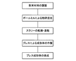
- the powder material of the light wavelength conversion member 9 which is a ceramic sintered body was weighed (that is, prepared) so as to satisfy the configuration of the embodiment.
- an organic solvent and a dispersant were added to the prepared powder material, and pulverized and mixed with a ball mill to prepare a slurry.
- the obtained slurry was dried and granulated.
- the obtained granulated powder was press-molded.
- the press-molded body was fired at a predetermined temperature for a predetermined time to obtain a ceramic sintered body.
- a ceramic sintered body may be obtained by firing a sheet molded body obtained by sheet forming a slurry. [1-3. effect] Next, the effect of this embodiment will be described.
- the ceramic sintered body is represented by A 3 B 5 O 12 : Ce composed of at least one element selected from the element group. It has a structure. With this composition, blue light can be efficiently converted into visible light.
- the area ratio a between the light transmitting phase and the fluorescent phase in the cross section of the light wavelength conversion member 9 is 0.3 ⁇ a ⁇ 34, and the interface length y of the fluorescent phase is 300 ⁇ m ⁇ y. ⁇ 1050 ⁇ m. Therefore, when the light wavelength conversion member 9 is irradiated with light from the light emitting element 5, for example, there is an effect that high illuminance and fluorescence intensity can be obtained and color unevenness is small.
- the particle size ratio x between the average particle size r1 of the light transmitting phase particles and the average particle size r2 of the fluorescent phase particles is 1.1 ⁇ x ⁇ 2.1, and the light transmitting phase
- the average particle diameter r1 of the particles is in the range of 0.2 ⁇ m to 6 ⁇ m, and the average particle diameter r2 of the fluorescent phase particles is in the range of 0.1 ⁇ m to 4 ⁇ m.
- the compound represented by the chemical formula A 3 B 5 O 12 : Ce is in the range of 3 vol% to 70 vol% of the entire ceramic sintered body.
- the Ce concentration in the compound represented by the chemical formula A 3 B 5 O 12 : Ce is in the range of 0.1 mol% to 1.0 mol% with respect to the element A of the compound.
- ⁇ Relative density> The relative density of the ceramic sintered body of each sample was calculated by measuring the density by the Archimedes method and converting the measured density to the relative density.
- ⁇ Area ratio> The ceramic sintered body of each sample was broken, the fractured surface was mirror-polished, and the polished surface was observed with a scanning electron microscope (SEM) to obtain a 5000-fold SEM image.
- SEM scanning electron microscope
- the area ST of the light transmitting phase and the area SK of the fluorescent phase were measured in the region of 500 ⁇ m 2 , respectively. Then, an area ratio a between the area ST of the light transmitting phase and the area SK of the fluorescent phase was obtained by calculation of ST / SK.
- the area was obtained by processing the SEM image with image analysis software (for example, Winloof).
- image analysis software for example, Winloof.
- the area ratio a may be obtained by converting to 500 ⁇ m 2 after measurement in a specific visual field range. The same applies to the interface length described later, and may be converted per 500 ⁇ m 2 .
- ⁇ Average crystal grain size> The ceramic sintered body of each sample was fractured, and the fractured surface was mirror-polished, followed by thermal etching at 1350 ° C. The etched surface was observed with an SEM, and images of 2500 times (that is, SEM images) were obtained at arbitrary five positions in the ceramic sintered body.
- a schematic diagram of an example of the SEM image is shown in FIG. 4, where the bright part is the fluorescent phase particle and the dark part is the light transmitting phase particle.
- the average crystal grain size (that is, the average grain size) of the fluorescent phase particles and the transparent phase particles is determined by the intercept method. Asked. That is, the average particle diameter r2 of the fluorescent phase particles and the average particle diameter r1 of the light transmitting phase particles were determined in the entire five regions.
- the particle size ratio x was calculated from the average particle size r2 of the obtained fluorescent phase particles and the average particle size r1 of the light transmitting phase particles using the following formula (1).
- Particle size ratio x transparent phase particle average particle size r1 / fluorescent phase particle average particle size r2 (1) ⁇ Interface length> Using the image analysis software (for example, Winloof) for the 5000 times SEM image used when determining the area ratio, the interface length for each fluorescent phase in each region at any five positions Asked. That is, the interface length in units of a single fluorescent phase was determined. Moreover, in the area
- image analysis software for example, Winloof
- region in five positions is each a magnitude
- region of five positions was calculated
- FIG. 3 shows an example of the interface length, that is, the interface length of the fluorescent phase in units of fluorescent phase.
- the length of the white circular line surrounding one fluorescent phase that is, one light gray bright portion
- the interface length in units of fluorescent phase is the interface length in units of fluorescent phase.
- the illuminance was measured with a luminometer. Specifically, blue LD light having a wavelength of 465 nm is condensed with a lens to a width of 0.5 mm for each sample processed to a 13 mm square ⁇ thickness 0.2 mm, and this is irradiated and transmitted from the opposite surface. The illuminance of the incoming light was measured with a spectral irradiance meter (CL-500A manufactured by Konica Minolta).
- the illuminance was evaluated as a relative value (%) when the strength of the YAG: Ce single crystal was 100. ⁇ Color unevenness> Color unevenness (that is, color variation) was evaluated by measuring chromaticity variation with an illuminometer.
- blue LD light having a wavelength of 465 nm is condensed with a lens to a width of 0.5 mm for each sample processed to a 13 mm square ⁇ thickness 0.2 mm, and this is irradiated and transmitted from the opposite surface.
- the chromaticity of the incoming light was measured with a spectral irradiance meter (CL-500A manufactured by Konica Minolta).
- the irradiation is performed by dividing the 9 mm square central portion into 9 regions at intervals of 3 mm, and the chromaticity (X direction) of each region. Variation ( ⁇ x) was evaluated.
- the variation ( ⁇ x) indicates the maximum value of deviation in the chromaticity direction, and preferably ⁇ x ⁇ 0.03.
- the chromaticity is an international display method established in 1931 by the International Commission on Illumination (CIE) and is a chromaticity represented by the CIE-XYZ color system. That is, the chromaticity is represented by an xy chromaticity diagram (so-called CIE chromaticity diagram) in which the three primary colors on the color are digitized and the colors are expressed in the xy coordinate space.
- CIE International Commission on Illumination
- the fluorescence intensity was evaluated as a relative value (%) when the intensity of the YAG: Ce single crystal was 100.
- [2-2. Sample manufacturing method and evaluation results] Next, a manufacturing method of each sample and an evaluation result of each sample will be described.
- the amount of A 3 B 5 O 12 : Ce was fixed at 30 vol% of the entire ceramic sintered body.
- the Ce concentration was fixed at 0.3 mol% with respect to the A element.
- These powders were put into a ball mill together with ethanol and pulverized and mixed for 4 to 48 hours.
- the obtained slurry was dried and granulated, and the obtained granulated powder was press-molded.
- the obtained molded body was fired in an air atmosphere. At this time, firing was performed at a firing temperature of 1500 to 1800 ° C. and a holding time of 2 to 10 hours.
- the pulverization time is longer than 30 hours and the firing temperature is 150.
- the temperature was 0 ° C. and the holding time was 2 to 5 hours.
- the pulverization time was 16 hours, the firing temperature was 1500 ° C. to 1750 ° C., and the holding time was 10 hours.
- each sample of Example 1 can be obtained by changing a grinding
- Example 2 Samples of ceramic sintered bodies No. 10 to 19 were prepared under the conditions shown in Table 1 below.
- the method for preparing the sample of Example 2 is basically the same as that of Example 1. However, the grinding time was fixed at 16 hours, the firing temperature was 1600 ° C., and the holding time was 10 hours. Further, the amount of A 3 B 5 O 12 : Ce was adjusted to 1 vol% to 80 vol% of the whole.
- the sample No. 10 having a small amount of A 3 B 5 O 12 : Ce of 1 vol% had low fluorescence intensity due to insufficient fluorescence. Also, A 3 B 5 O 12 : No. 19 with a large Ce content of 80 vol% In this sample, the temperature rise accompanied by the decrease in heat conduction became remarkable, and the emission intensity decreased due to the temperature quenching.
- Example 3 Under the conditions shown in Table 1 below, samples of ceramic sintered bodies No. 20 to 26 were produced.
- the method for producing the sample of Example 3 is basically the same as that of Example 1.
- Example 2 the grinding time and firing conditions were the same as in Example 2.
- the amount of A 3 B 5 O 12 : Ce was fixed at 30 vol% of the whole, and the amount of Ce was set to 0.05 vol% to 2.0 vol%.
- the ceramic sintered body of each sample obtained by this manufacturing method was evaluated by the above-described evaluation method. The results are shown in Table 1 below.
- Example 4 Under the conditions shown in Table 1 below, samples of ceramic sintered bodies No. 27 to 30 were prepared. The method for producing the sample of Example 3 is basically the same as that of Example 1.
- the ceramic sintered body of each sample obtained by this manufacturing method was evaluated by the above-described evaluation method. The results are shown in Table 1 below. As is clear from Table 1, all of the sintered ceramics of Nos. 27 to 30 were satisfactory in terms of illuminance, fluorescence intensity, and color unevenness.
- the sample was produced by atmospheric firing, but in addition, a sample having equivalent performance by hot press firing, vacuum firing, reducing atmosphere firing, HIP, or a firing method combining these. Can be produced.
- Examples of uses of the light wavelength conversion member and the light emitting device include various uses such as phosphors, light wavelength conversion devices, headlamps, illumination, and optical devices such as projectors.
- the light-emitting element used in the light-emitting device is not particularly limited, and various elements such as well-known LEDs and LDs can be employed.
Landscapes
- Chemical & Material Sciences (AREA)
- Engineering & Computer Science (AREA)
- Ceramic Engineering (AREA)
- Organic Chemistry (AREA)
- Materials Engineering (AREA)
- Manufacturing & Machinery (AREA)
- Structural Engineering (AREA)
- Inorganic Chemistry (AREA)
- Physics & Mathematics (AREA)
- General Physics & Mathematics (AREA)
- Optics & Photonics (AREA)
- Luminescent Compositions (AREA)
- Led Device Packages (AREA)
Abstract
La présente invention concerne un élément de conversion de longueur d'onde optique et un dispositif électroluminescent qui ont un éclairement élevé et une intensité de fluorescence élevée et qui sont capables de supprimer une non-uniformité de couleur. Un élément de conversion de longueur d'onde optique 9 comprend un corps fritté en céramique qui a une phase fluorescente principalement constituée de particules de cristal fluorescent et une phase translucide principalement constituée de particules de cristal translucide. Les particules cristallines de la phase fluorescente ont une composition représentée par la formule chimique a 3 B 5 O 12 : Ce, l'élément A et l'élément B comprenant au moins un type d'élément choisi parmi les groupes d'éléments suivants respectifs, qui est, l'élément a peut être choisi parmi les "lanthanides à l'exclusion de Sc, Y, et Ce" et l'élément B peut être choisi parmi "Al et Ga" En outre, dans l'élément de conversion de longueur d'onde optique 9, une section transversale de l'élément de conversion de longueur d'onde optique 9 a un rapport de surface entre la phase translucide et la phase fluorescente qui satisfait la condition: 0,3 < a < 34, et la phase fluorescente a une longueur d'interface y qui satisfait à la condition : 300 μm < y < 1050 µm.
Priority Applications (4)
| Application Number | Priority Date | Filing Date | Title |
|---|---|---|---|
| US16/342,390 US10727378B2 (en) | 2016-10-28 | 2017-10-20 | Optical wavelength conversion member and light-emitting device |
| KR1020197011086A KR102229730B1 (ko) | 2016-10-28 | 2017-10-20 | 광 파장 변환 부재 및 발광 장치 |
| CN201780066919.2A CN109923446B (zh) | 2016-10-28 | 2017-10-20 | 光波长转换构件及发光装置 |
| EP17865959.5A EP3534193B1 (fr) | 2016-10-28 | 2017-10-20 | Élément de conversion de longueur d'onde et dispositif électroluminescent |
Applications Claiming Priority (10)
| Application Number | Priority Date | Filing Date | Title |
|---|---|---|---|
| JP2016211843 | 2016-10-28 | ||
| JP2016-211843 | 2016-10-28 | ||
| JP2016-215303 | 2016-11-02 | ||
| JP2016215303A JP6486315B2 (ja) | 2016-11-02 | 2016-11-02 | 光波長変換部材及び発光装置 |
| JP2017-015653 | 2017-01-31 | ||
| JP2017015653 | 2017-01-31 | ||
| JP2017100204 | 2017-05-19 | ||
| JP2017-100204 | 2017-05-19 | ||
| JP2017-148393 | 2017-07-31 | ||
| JP2017148393A JP6499237B2 (ja) | 2017-07-31 | 2017-07-31 | 光波長変換部材及び発光装置 |
Publications (1)
| Publication Number | Publication Date |
|---|---|
| WO2018079421A1 true WO2018079421A1 (fr) | 2018-05-03 |
Family
ID=62023459
Family Applications (1)
| Application Number | Title | Priority Date | Filing Date |
|---|---|---|---|
| PCT/JP2017/037920 Ceased WO2018079421A1 (fr) | 2016-10-28 | 2017-10-20 | Élément de conversion de longueur d'onde et dispositif électroluminescent |
Country Status (6)
| Country | Link |
|---|---|
| US (1) | US10727378B2 (fr) |
| EP (1) | EP3534193B1 (fr) |
| KR (1) | KR102229730B1 (fr) |
| CN (1) | CN109923446B (fr) |
| TW (1) | TWI668295B (fr) |
| WO (1) | WO2018079421A1 (fr) |
Cited By (2)
| Publication number | Priority date | Publication date | Assignee | Title |
|---|---|---|---|---|
| WO2020013016A1 (fr) * | 2018-07-11 | 2020-01-16 | 日本特殊陶業株式会社 | Élément de conversion de longueur d'onde optique et dispositif électroluminescent |
| EP3832360A4 (fr) * | 2018-07-31 | 2022-04-20 | NGK Spark Plug Co., Ltd. | Élément de conversion de longueur d'onde de lumière et dispositif électroluminescent |
Families Citing this family (6)
| Publication number | Priority date | Publication date | Assignee | Title |
|---|---|---|---|---|
| TWI802899B (zh) * | 2020-06-08 | 2023-05-21 | 日商日本特殊陶業股份有限公司 | 螢光板、波長轉換構件及光源裝置 |
| KR102665901B1 (ko) * | 2020-06-08 | 2024-05-13 | 니혼도꾸슈도교 가부시키가이샤 | 형광판, 파장 변환 부재, 및, 광원 장치 |
| JP7617364B2 (ja) | 2020-08-07 | 2025-01-20 | 日亜化学工業株式会社 | 希土類アルミン酸塩焼結体及びその製造方法 |
| EP4328207A1 (fr) * | 2022-08-24 | 2024-02-28 | Nichia Corporation | Corps fritté et procédé de production de corps fritté |
| US20240186464A1 (en) | 2022-12-02 | 2024-06-06 | Ams-Osram International Gmbh | Converter and method for producing the same |
| CN119371181A (zh) * | 2023-07-20 | 2025-01-28 | 深圳市绎立锐光科技开发有限公司 | 一种发光陶瓷、制备方法、波长转换装置及发光装置 |
Citations (10)
| Publication number | Priority date | Publication date | Assignee | Title |
|---|---|---|---|---|
| WO2006001316A1 (fr) * | 2004-06-24 | 2006-01-05 | Ube Industries, Ltd. | Dispositif à diode électroluminescente blanche |
| WO2011102566A1 (fr) * | 2010-02-16 | 2011-08-25 | The Industry & Academic Cooperation In Chungnam National University (Iac) | Synthèse rapide en phase solide de substances phosphorescentes de grenat d'yttrium et d'aluminium émettant de la lumière jaune |
| WO2011125422A1 (fr) * | 2010-03-31 | 2011-10-13 | 宇部興産株式会社 | Composites céramiques pour la conversion de la lumière, procédé pour la production de ceux-ci, et dispositifs émettant de la lumière constitués des mêmes |
| JP2012062459A (ja) * | 2010-08-18 | 2012-03-29 | Covalent Materials Corp | セラミックス複合体 |
| JP2013147643A (ja) * | 2011-12-22 | 2013-08-01 | Shin-Etsu Chemical Co Ltd | イットリウムセリウムアルミニウムガーネット蛍光体の製造方法 |
| JP2014132084A (ja) | 2012-03-30 | 2014-07-17 | Covalent Materials Corp | セラミックス複合体 |
| JP2015034120A (ja) | 2013-07-12 | 2015-02-19 | コバレントマテリアル株式会社 | アルミナセラミックス部材 |
| JP2015149394A (ja) | 2014-02-06 | 2015-08-20 | スタンレー電気株式会社 | 波長変換体及びそれを用いた発光装置 |
| WO2016117623A1 (fr) * | 2015-01-21 | 2016-07-28 | 三菱化学株式会社 | Luminophore fritté, dispositif électroluminescent, dispositif d'éclairage, phare de véhicule et procédé de fabrication de luminophore fritté |
| WO2017170609A1 (fr) * | 2016-03-29 | 2017-10-05 | 三菱化学株式会社 | Corps fluorescent, dispositif d'émission de lumière, appareil d'éclairage, et appareil d'affichage d'image |
Family Cites Families (13)
| Publication number | Priority date | Publication date | Assignee | Title |
|---|---|---|---|---|
| JP3904874B2 (ja) * | 2001-10-03 | 2007-04-11 | 京セラ株式会社 | 半導体製造装置用部材 |
| DE10361661A1 (de) * | 2003-07-14 | 2005-03-17 | Osram Opto Semiconductors Gmbh | Licht emittierendes Bauelement mit einem Lumineszenz-Konversionselement |
| JP4513541B2 (ja) * | 2004-12-17 | 2010-07-28 | 宇部興産株式会社 | 光変換用セラミック複合体を用いた発光装置 |
| EP1862035B1 (fr) | 2005-03-14 | 2013-05-15 | Koninklijke Philips Electronics N.V. | Phosphore dans une structure ceramique polycristalline et element lumineux le comprenant |
| US8093799B2 (en) * | 2006-09-25 | 2012-01-10 | Ube Industries, Ltd. | Ceramic composite for phototransformation and light emitting device using the same |
| DE102007010719A1 (de) * | 2007-03-06 | 2008-09-11 | Merck Patent Gmbh | Leuchtstoffe bestehend aus dotierten Granaten für pcLEDs |
| JP5650885B2 (ja) | 2008-12-27 | 2015-01-07 | 日亜化学工業株式会社 | 波長変換焼結体及びこれを用いた発光装置、並びに波長変換焼結体の製造方法 |
| EP2826835B1 (fr) * | 2012-03-15 | 2018-03-07 | Kabushiki Kaisha Toshiba | Scintillateur solide, détecteur de rayonnement et dispositif d'examen radiographique |
| JP2013227481A (ja) | 2012-03-30 | 2013-11-07 | Covalent Materials Corp | セラミックス複合体 |
| WO2013146994A1 (fr) | 2012-03-30 | 2013-10-03 | 宇部興産株式会社 | Complexe céramique pour la conversion de la lumière et dispositif électroluminescent l'utilisant |
| MY177277A (en) * | 2014-03-03 | 2020-09-10 | Covalent Mat Corporation | Wavelength converting member |
| KR20160135294A (ko) * | 2014-03-18 | 2016-11-25 | 우베 고산 가부시키가이샤 | 광변환용 세라믹스 복합 재료, 그의 제조 방법, 및 그것을 구비한 발광 장치 |
| JP6492824B2 (ja) | 2015-03-18 | 2019-04-03 | 宇部興産株式会社 | 光変換用セラミックス複合材料およびその製造方法 |
-
2017
- 2017-10-20 EP EP17865959.5A patent/EP3534193B1/fr active Active
- 2017-10-20 US US16/342,390 patent/US10727378B2/en active Active
- 2017-10-20 WO PCT/JP2017/037920 patent/WO2018079421A1/fr not_active Ceased
- 2017-10-20 KR KR1020197011086A patent/KR102229730B1/ko active Active
- 2017-10-20 CN CN201780066919.2A patent/CN109923446B/zh active Active
- 2017-10-27 TW TW106137049A patent/TWI668295B/zh active
Patent Citations (10)
| Publication number | Priority date | Publication date | Assignee | Title |
|---|---|---|---|---|
| WO2006001316A1 (fr) * | 2004-06-24 | 2006-01-05 | Ube Industries, Ltd. | Dispositif à diode électroluminescente blanche |
| WO2011102566A1 (fr) * | 2010-02-16 | 2011-08-25 | The Industry & Academic Cooperation In Chungnam National University (Iac) | Synthèse rapide en phase solide de substances phosphorescentes de grenat d'yttrium et d'aluminium émettant de la lumière jaune |
| WO2011125422A1 (fr) * | 2010-03-31 | 2011-10-13 | 宇部興産株式会社 | Composites céramiques pour la conversion de la lumière, procédé pour la production de ceux-ci, et dispositifs émettant de la lumière constitués des mêmes |
| JP2012062459A (ja) * | 2010-08-18 | 2012-03-29 | Covalent Materials Corp | セラミックス複合体 |
| JP2013147643A (ja) * | 2011-12-22 | 2013-08-01 | Shin-Etsu Chemical Co Ltd | イットリウムセリウムアルミニウムガーネット蛍光体の製造方法 |
| JP2014132084A (ja) | 2012-03-30 | 2014-07-17 | Covalent Materials Corp | セラミックス複合体 |
| JP2015034120A (ja) | 2013-07-12 | 2015-02-19 | コバレントマテリアル株式会社 | アルミナセラミックス部材 |
| JP2015149394A (ja) | 2014-02-06 | 2015-08-20 | スタンレー電気株式会社 | 波長変換体及びそれを用いた発光装置 |
| WO2016117623A1 (fr) * | 2015-01-21 | 2016-07-28 | 三菱化学株式会社 | Luminophore fritté, dispositif électroluminescent, dispositif d'éclairage, phare de véhicule et procédé de fabrication de luminophore fritté |
| WO2017170609A1 (fr) * | 2016-03-29 | 2017-10-05 | 三菱化学株式会社 | Corps fluorescent, dispositif d'émission de lumière, appareil d'éclairage, et appareil d'affichage d'image |
Non-Patent Citations (1)
| Title |
|---|
| See also references of EP3534193A4 |
Cited By (9)
| Publication number | Priority date | Publication date | Assignee | Title |
|---|---|---|---|---|
| WO2020013016A1 (fr) * | 2018-07-11 | 2020-01-16 | 日本特殊陶業株式会社 | Élément de conversion de longueur d'onde optique et dispositif électroluminescent |
| JPWO2020013016A1 (ja) * | 2018-07-11 | 2020-07-16 | 日本特殊陶業株式会社 | 光波長変換部材及び発光装置 |
| KR20210006959A (ko) * | 2018-07-11 | 2021-01-19 | 니뽄 도쿠슈 도교 가부시키가이샤 | 광파장 변환 부재 및 발광 장치 |
| CN112384832A (zh) * | 2018-07-11 | 2021-02-19 | 日本特殊陶业株式会社 | 光波长转换构件和发光装置 |
| EP3822671A4 (fr) * | 2018-07-11 | 2022-04-20 | NGK Spark Plug Co., Ltd. | Élément de conversion de longueur d'onde optique et dispositif électroluminescent |
| US11560513B2 (en) | 2018-07-11 | 2023-01-24 | Ngk Spark Plug Co., Ltd. | Optical wavelength conversion member and light-emitting device |
| KR102500926B1 (ko) | 2018-07-11 | 2023-02-17 | 니뽄 도쿠슈 도교 가부시키가이샤 | 광파장 변환 부재 및 발광 장치 |
| EP3832360A4 (fr) * | 2018-07-31 | 2022-04-20 | NGK Spark Plug Co., Ltd. | Élément de conversion de longueur d'onde de lumière et dispositif électroluminescent |
| US11945987B2 (en) | 2018-07-31 | 2024-04-02 | Niterra Co., Ltd. | Light wavelength conversion member and light-emitting device |
Also Published As
| Publication number | Publication date |
|---|---|
| EP3534193B1 (fr) | 2021-12-22 |
| TWI668295B (zh) | 2019-08-11 |
| CN109923446B (zh) | 2021-05-18 |
| US20190259918A1 (en) | 2019-08-22 |
| CN109923446A (zh) | 2019-06-21 |
| US10727378B2 (en) | 2020-07-28 |
| KR102229730B1 (ko) | 2021-03-18 |
| EP3534193A1 (fr) | 2019-09-04 |
| TW201821594A (zh) | 2018-06-16 |
| EP3534193A4 (fr) | 2020-05-13 |
| KR20190053240A (ko) | 2019-05-17 |
Similar Documents
| Publication | Publication Date | Title |
|---|---|---|
| CN109923446B (zh) | 光波长转换构件及发光装置 | |
| CN109716178B (zh) | 光波长转换部件及发光装置 | |
| Waetzig et al. | Influence of sample thickness and concentration of Ce dopant on the optical properties of YAG: Ce ceramic phosphors for white LEDs | |
| US10982140B2 (en) | Nitride phosphor particle dispersion-type sialon ceramic, fluorescent member, and method for producing nitride phosphor particle dispersion-type sialon ceramic | |
| WO2018021418A1 (fr) | Phosphore fritté, dispositif électroluminescent, dispositif d'éclairage et lampe témoin de véhicule | |
| JP2012062444A (ja) | 緑色蛍光体 | |
| WO2015141711A1 (fr) | Matériau composite céramique de conversion optique, son procédé de production et dispositif électroluminescent muni de celui-ci | |
| JP6499237B2 (ja) | 光波長変換部材及び発光装置 | |
| US20190245118A1 (en) | Light wavelength conversion member and light emitting device | |
| KR102500926B1 (ko) | 광파장 변환 부재 및 발광 장치 | |
| JP6591951B2 (ja) | 光波長変換部材及び発光装置 | |
| KR102318473B1 (ko) | 광 파장 변환 부재의 제조 방법, 광 파장 변환 부재, 광 파장 변환 부품, 및 발광 장치 | |
| WO2018079373A1 (fr) | Élément de conversion de longueur d'onde de lumière et dispositif électroluminescent | |
| JP6741885B2 (ja) | 光波長変換部材及び発光装置 | |
| JP5615222B2 (ja) | 緑色蛍光体 | |
| KR20170093320A (ko) | 광 확산제를 사용한 형광체 플레이트 |
Legal Events
| Date | Code | Title | Description |
|---|---|---|---|
| 121 | Ep: the epo has been informed by wipo that ep was designated in this application |
Ref document number: 17865959 Country of ref document: EP Kind code of ref document: A1 |
|
| ENP | Entry into the national phase |
Ref document number: 20197011086 Country of ref document: KR Kind code of ref document: A |
|
| NENP | Non-entry into the national phase |
Ref country code: DE |
|
| ENP | Entry into the national phase |
Ref document number: 2017865959 Country of ref document: EP Effective date: 20190528 |