WO2018079540A1 - 電動アクチュエータ - Google Patents
電動アクチュエータ Download PDFInfo
- Publication number
- WO2018079540A1 WO2018079540A1 PCT/JP2017/038331 JP2017038331W WO2018079540A1 WO 2018079540 A1 WO2018079540 A1 WO 2018079540A1 JP 2017038331 W JP2017038331 W JP 2017038331W WO 2018079540 A1 WO2018079540 A1 WO 2018079540A1
- Authority
- WO
- WIPO (PCT)
- Prior art keywords
- gear
- drive motor
- actuator
- motor
- electric actuator
- Prior art date
- Legal status (The legal status is an assumption and is not a legal conclusion. Google has not performed a legal analysis and makes no representation as to the accuracy of the status listed.)
- Ceased
Links
Images


Classifications
-
- H—ELECTRICITY
- H02—GENERATION; CONVERSION OR DISTRIBUTION OF ELECTRIC POWER
- H02K—DYNAMO-ELECTRIC MACHINES
- H02K7/00—Arrangements for handling mechanical energy structurally associated with dynamo-electric machines, e.g. structural association with mechanical driving motors or auxiliary dynamo-electric machines
- H02K7/06—Means for converting reciprocating motion into rotary motion or vice versa
-
- F—MECHANICAL ENGINEERING; LIGHTING; HEATING; WEAPONS; BLASTING
- F16—ENGINEERING ELEMENTS AND UNITS; GENERAL MEASURES FOR PRODUCING AND MAINTAINING EFFECTIVE FUNCTIONING OF MACHINES OR INSTALLATIONS; THERMAL INSULATION IN GENERAL
- F16H—GEARING
- F16H25/00—Gearings comprising primarily only cams, cam-followers and screw-and-nut mechanisms
- F16H25/18—Gearings comprising primarily only cams, cam-followers and screw-and-nut mechanisms for conveying or interconverting oscillating or reciprocating motions
- F16H25/20—Screw mechanisms
-
- F—MECHANICAL ENGINEERING; LIGHTING; HEATING; WEAPONS; BLASTING
- F16—ENGINEERING ELEMENTS AND UNITS; GENERAL MEASURES FOR PRODUCING AND MAINTAINING EFFECTIVE FUNCTIONING OF MACHINES OR INSTALLATIONS; THERMAL INSULATION IN GENERAL
- F16H—GEARING
- F16H25/00—Gearings comprising primarily only cams, cam-followers and screw-and-nut mechanisms
- F16H25/18—Gearings comprising primarily only cams, cam-followers and screw-and-nut mechanisms for conveying or interconverting oscillating or reciprocating motions
-
- F—MECHANICAL ENGINEERING; LIGHTING; HEATING; WEAPONS; BLASTING
- F16—ENGINEERING ELEMENTS AND UNITS; GENERAL MEASURES FOR PRODUCING AND MAINTAINING EFFECTIVE FUNCTIONING OF MACHINES OR INSTALLATIONS; THERMAL INSULATION IN GENERAL
- F16H—GEARING
- F16H57/00—General details of gearing
- F16H57/02—Gearboxes; Mounting gearing therein
- F16H57/021—Shaft support structures, e.g. partition walls, bearing eyes, casing walls or covers with bearings
-
- H—ELECTRICITY
- H02—GENERATION; CONVERSION OR DISTRIBUTION OF ELECTRIC POWER
- H02K—DYNAMO-ELECTRIC MACHINES
- H02K7/00—Arrangements for handling mechanical energy structurally associated with dynamo-electric machines, e.g. structural association with mechanical driving motors or auxiliary dynamo-electric machines
- H02K7/10—Structural association with clutches, brakes, gears, pulleys or mechanical starters
- H02K7/116—Structural association with clutches, brakes, gears, pulleys or mechanical starters with gears
-
- F—MECHANICAL ENGINEERING; LIGHTING; HEATING; WEAPONS; BLASTING
- F16—ENGINEERING ELEMENTS AND UNITS; GENERAL MEASURES FOR PRODUCING AND MAINTAINING EFFECTIVE FUNCTIONING OF MACHINES OR INSTALLATIONS; THERMAL INSULATION IN GENERAL
- F16H—GEARING
- F16H1/00—Toothed gearings for conveying rotary motion
- F16H1/28—Toothed gearings for conveying rotary motion with gears having orbital motion
-
- F—MECHANICAL ENGINEERING; LIGHTING; HEATING; WEAPONS; BLASTING
- F16—ENGINEERING ELEMENTS AND UNITS; GENERAL MEASURES FOR PRODUCING AND MAINTAINING EFFECTIVE FUNCTIONING OF MACHINES OR INSTALLATIONS; THERMAL INSULATION IN GENERAL
- F16H—GEARING
- F16H25/00—Gearings comprising primarily only cams, cam-followers and screw-and-nut mechanisms
- F16H25/18—Gearings comprising primarily only cams, cam-followers and screw-and-nut mechanisms for conveying or interconverting oscillating or reciprocating motions
- F16H25/20—Screw mechanisms
- F16H2025/2031—Actuator casings
-
- F—MECHANICAL ENGINEERING; LIGHTING; HEATING; WEAPONS; BLASTING
- F16—ENGINEERING ELEMENTS AND UNITS; GENERAL MEASURES FOR PRODUCING AND MAINTAINING EFFECTIVE FUNCTIONING OF MACHINES OR INSTALLATIONS; THERMAL INSULATION IN GENERAL
- F16H—GEARING
- F16H25/00—Gearings comprising primarily only cams, cam-followers and screw-and-nut mechanisms
- F16H25/18—Gearings comprising primarily only cams, cam-followers and screw-and-nut mechanisms for conveying or interconverting oscillating or reciprocating motions
- F16H25/20—Screw mechanisms
- F16H2025/2062—Arrangements for driving the actuator
- F16H2025/2081—Parallel arrangement of drive motor to screw axis
-
- F—MECHANICAL ENGINEERING; LIGHTING; HEATING; WEAPONS; BLASTING
- F16—ENGINEERING ELEMENTS AND UNITS; GENERAL MEASURES FOR PRODUCING AND MAINTAINING EFFECTIVE FUNCTIONING OF MACHINES OR INSTALLATIONS; THERMAL INSULATION IN GENERAL
- F16H—GEARING
- F16H25/00—Gearings comprising primarily only cams, cam-followers and screw-and-nut mechanisms
- F16H25/18—Gearings comprising primarily only cams, cam-followers and screw-and-nut mechanisms for conveying or interconverting oscillating or reciprocating motions
- F16H25/20—Screw mechanisms
- F16H2025/2062—Arrangements for driving the actuator
- F16H2025/2087—Arrangements for driving the actuator using planetary gears
-
- F—MECHANICAL ENGINEERING; LIGHTING; HEATING; WEAPONS; BLASTING
- F16—ENGINEERING ELEMENTS AND UNITS; GENERAL MEASURES FOR PRODUCING AND MAINTAINING EFFECTIVE FUNCTIONING OF MACHINES OR INSTALLATIONS; THERMAL INSULATION IN GENERAL
- F16H—GEARING
- F16H25/00—Gearings comprising primarily only cams, cam-followers and screw-and-nut mechanisms
- F16H25/18—Gearings comprising primarily only cams, cam-followers and screw-and-nut mechanisms for conveying or interconverting oscillating or reciprocating motions
- F16H25/20—Screw mechanisms
- F16H25/2015—Means specially adapted for stopping actuators in the end position; Position sensing means
-
- F—MECHANICAL ENGINEERING; LIGHTING; HEATING; WEAPONS; BLASTING
- F16—ENGINEERING ELEMENTS AND UNITS; GENERAL MEASURES FOR PRODUCING AND MAINTAINING EFFECTIVE FUNCTIONING OF MACHINES OR INSTALLATIONS; THERMAL INSULATION IN GENERAL
- F16H—GEARING
- F16H25/00—Gearings comprising primarily only cams, cam-followers and screw-and-nut mechanisms
- F16H25/18—Gearings comprising primarily only cams, cam-followers and screw-and-nut mechanisms for conveying or interconverting oscillating or reciprocating motions
- F16H25/20—Screw mechanisms
- F16H25/22—Screw mechanisms with balls, rollers, or similar members between the co-operating parts; Elements essential to the use of such members
- F16H25/2204—Screw mechanisms with balls, rollers, or similar members between the co-operating parts; Elements essential to the use of such members with balls
Definitions
- the present invention relates to an electric actuator.
- Patent Document 1 proposes an electric linear actuator configured to transmit a driving force from an electric motor to a ball screw mechanism via a plurality of gears.
- an object of the present invention is to provide an electric actuator that can be reduced in size by reducing the number of parts.
- the present invention includes a drive motor, and a motion conversion mechanism that converts the rotational motion of the drive motor into an axial linear motion parallel to the output shaft of the drive motor.
- An electric actuator comprising: a transmission gear mechanism that transmits a driving force from the drive motor to the motion conversion mechanism; and a speed reduction mechanism that decelerates the rotational motion of the drive motor and outputs it to the transmission gear mechanism.
- One end of the rotating shaft of the gear is rotatably supported by a bearing, and the other end of the rotating shaft of the gear is rotatably supported by an output shaft of a driving motor.
- one end of the bearing can be omitted by rotatably supporting one end of the rotating shaft by the output shaft of the driving motor.
- the number of parts is reduced, so that the cost can be reduced and the electric actuator can be downsized in the axial direction.
- a sun gear integrally attached to the output shaft of the drive motor a ring gear disposed on the outer peripheral side of the sun gear, a plurality of planetary gears disposed between the sun gear and the ring gear and meshing with both gears, a plurality of A planetary gear reduction mechanism including a planetary gear carrier that rotatably holds the planetary gear and that is integrally attached to the rotation shaft of the gear of the transmission gear mechanism can be employed.
- the bearing that supports one end of the gear and the drive motor that supports the other end of the gear are both the same case (actuator case).
- the relative positional accuracy between the output shaft of the drive motor and the bearing is improved. That is, since the drive motor and the bearing are not attached to separate cases, the relative positions of the drive motor and the bearing are not affected by the assembling accuracy between the cases. Thereby, the accuracy of the position and posture of the gear supported by the drive motor and the bearing is improved.
- the speed reduction mechanism by attaching the speed reduction mechanism to the actuator case together with the drive motor, the relative positional accuracy of the speed reducer, the drive motor and the bearing can be improved, and the accuracy of the gear position and orientation can be improved.
- the number of parts is reduced, and the cost and size of the electric actuator can be reduced.
- FIG. 2 is a cross-sectional view taken along the line AA in FIG. It is a longitudinal cross-sectional view of the electric actuator which concerns on a comparative example.
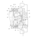
- FIG. 1 is a longitudinal sectional view of an electric actuator according to an embodiment of the present invention
- FIG. 2 is an exploded perspective view of the electric actuator.
- the electric actuator 1 includes a motor unit 4 including a drive motor 2 and a speed reduction mechanism 3, a drive transmission including a transmission gear mechanism 5 and a motion conversion mechanism 6.
- the conversion unit 7 is the main configuration. As will be described later, the motor unit 4 may not include the speed reduction mechanism 3.
- each part constituting the electric actuator 1 has an exterior case, and the components are accommodated or supported in each exterior case.
- the motor unit 4 has a motor case 8 that houses the drive motor 2 and the speed reduction mechanism 3, and the drive transmission conversion unit 7 is an actuator case that supports the transmission gear mechanism 5 and the motion conversion mechanism 6.
- the motor case 8 includes a motor case main body 69 that houses the driving motor 2 and a cap member 32 that is formed separately from the motor case main body 69.
- the motor case main body 69 is attached to the actuator case 9 so that it can be connected and disconnected in the axial direction of the drive motor 2, and the drive motor 2 and the speed reduction mechanism 3 can also be connected and disconnected to the actuator case 9 in the axial direction. Is attached.
- a shaft case 10 that accommodates a part of the motion conversion mechanism 6 is attached to the actuator case 9 on the opposite side to the motor case 8 side so as to be separable in the axial direction.
- these exterior cases are mutually fastened and assembled
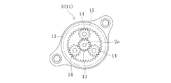
- FIG. 3 is a diagram of the speed reduction mechanism viewed from the axial direction.
- the speed reduction mechanism 3 includes a planetary gear speed reduction mechanism 11 including a plurality of gears and the like.
- the planetary gear reduction mechanism 11 includes a ring gear 12, a sun gear 13, a plurality of planetary gears 14, and a planetary gear carrier 15.
- a sun gear 13 is disposed in the center of the ring gear 12, and the output shaft 2 a of the drive motor 2 is press-fitted into the sun gear 13.
- a plurality of planetary gears 14 are arranged between the ring gear 12 and the sun gear 13 so as to mesh with them. Each planetary gear 14 is rotatably held by a planetary gear carrier 15.
- the planetary gear speed reduction mechanism 11 rotates the sun gear 13 integrally attached to the output shaft 2a of the drive motor 2, and the planetary gears 14 rotate along with the rotation of the ring gear. Revolve along 12 The planetary gear carrier 15 is rotated by the revolving motion of the planetary gear 14. Thereby, the rotation of the driving motor 2 is decelerated and transmitted, and the rotational torque increases. As described above, the driving force is transmitted through the planetary gear speed reduction mechanism 11, whereby a large output of the electric actuator 1 can be obtained, and the driving motor 2 can be downsized.
- an inexpensive (brushed) DC motor is used as the driving motor 2, but other motors such as a brushless motor may be used.
- the transmission gear mechanism 5 includes a small-diameter drive gear 16 as a first gear whose rotation shaft is arranged coaxially with the output shaft 2 a of the drive motor 2, and a drive A large-diameter driven gear 17 as a second gear meshing with the gear 16 is configured.
- a gear boss 18 (see FIG. 1), which is a rotating shaft, is press-fitted into the rotation center portion of the drive gear 16, and one end portion (right end portion in FIG. 1) of the gear boss 18 is attached to the actuator case 9.
- a rolling bearing 19 is rotatably supported.
- the drive gear 16 and the gear boss 18 may be integrally formed by sintering.
- the opposite end the left end in FIG.
- the gear boss 18 is supported by inserting the output shaft 2a of the drive motor 2 penetrating the sun gear 13 into the shaft hole 18a that opens to the end.
- the output shaft 2 a of the drive motor 2 is inserted in the relationship of a sliding bearing that can rotate relative to the gear boss 18.
- a lubricant such as grease may be filled in the shaft hole 18a of the gear boss 18 so that the relative rotation between the output shaft 2a of the drive motor 2 and the gear boss 18 can be smoothly performed.
- the gear boss 18 is made of a sintered alloy and is molded integrally with the drive gear 16, the sintered material is suitable as a sliding bearing because it retains lubricating oil.
- the gear boss 18 is attached so as to rotate integrally with the planetary gear carrier 15.
- a cylindrical portion 15 a (see FIG. 1) is provided at the center of the planetary gear carrier 15, and the cylindrical portion 15 a is press-fitted to the outer peripheral surface of the gear boss 18.
- the planetary gear carrier 15 may be made of resin, and the gear boss 18 may be insert-molded integrally with the planetary gear carrier 15.
- the drive gear 16 rotates integrally with the planetary gear carrier 15 and the driven gear 17 rotates.
- the rotation is decelerated (increased torque) from the small diameter drive gear 16 to the large diameter driven gear 17 and transmitted, but the drive gear 16 is driven to the driven gear 17 at a constant speed. You may make it transmit rotation by.
- the motion conversion mechanism 6 includes a ball screw 20 disposed on an axis parallel to the output shaft 2 a of the drive motor 2.
- the motion conversion mechanism 6 is not limited to the ball screw 20 and may be a sliding screw device. However, the ball screw 20 is more preferable from the viewpoint of reducing the rotational torque and reducing the size of the drive motor 2.
- the ball screw 20 includes a ball screw nut 21, a ball screw shaft 22, a large number of balls 23, and a circulation member (not shown).
- Helical grooves are formed on the inner peripheral surface of the ball screw nut 21 and the outer peripheral surface of the ball screw shaft 22, respectively, and balls 23 are accommodated in two rows between the spiral grooves.
- the ball screw nut 21 is rotatably supported by a double row bearing 24 attached to the actuator case 9.
- the double-row bearing 24 is press-fitted and fixed to the rear end side (right side in FIG. 1) of the ball screw shaft 22 from the portion where the driven gear 17 on the outer peripheral surface of the ball screw nut 21 is fixed.
- a pin 25 as a rotation restricting member provided at the rear end portion (the right end portion in FIG. 1) is inserted into an axial guide groove 10 a formed on the inner peripheral surface of the shaft case 10. The rotation is regulated by this.
- FIG. 1 shows a state in which the ball screw shaft 22 is disposed at the initial position where it is most retracted to the right in the drawing.
- the electric actuator 1 includes a lock mechanism 26 (see FIG. 2) for preventing the ball screw shaft 22 from unintentionally moving back and forth.
- the lock mechanism 26 is attached to the shaft case 10 and is configured to be engageable with and disengageable from a plurality of engagement holes 16a (see FIG. 2) formed over the circumferential direction of the drive gear 16. Even if an external force is input from the operation target device side to the ball screw shaft 22 side by the lock mechanism 26 engaging with one of the engagement holes 16a to restrict the rotation of the drive gear 16, the ball screw shaft 22 It is possible to prevent unintended advance / retreat and to keep the position in the advance / retreat direction at a predetermined position.
- Such a configuration including the lock mechanism 26 is suitable particularly when an electric actuator is applied to an application that requires position holding.
- a boot 27 that prevents foreign matter from entering the ball screw nut 21 is attached to the tip of the ball screw shaft 22.
- the boot 27 includes a large-diameter end portion 27a, a small-diameter end portion 27b, and a bellows portion 27c that extends and contracts in the axial direction.
- the small-diameter end portion 27b is fastened and fixed to the outer peripheral surface of the ball screw shaft 22 by a boot band 28.
- the large-diameter end portion 27 a of the boot 27 is fastened and fixed to the outer peripheral surface of a cylindrical boot mounting member 30 attached to the motor case body 69 by a boot band 29.
- a cylindrical boot cover 31 for protecting the boot 27 is provided outside the boot 27.
- a cylindrical attachment portion 31a (see FIG. 1) is provided inside the boot cover 31, and the boot mounting member 30 is attached to the attachment portion 31a. Both the boot cover 31 and the attachment portion 31 a are provided integrally with the motor case main body 69.
- a cap member 32 is mounted on the opposite side of the motor case body 69 from the actuator case 9 side.
- the cap member 32 is formed with an insertion hole 32a (see FIG. 2) through which a bus bar 33 for supplying electric power from a power source (not shown) to the drive motor 2 is inserted.
- a sensor case 34 (see FIG. 2) that houses a stroke sensor for detecting the stroke of the ball screw shaft 22 is integrally provided on the outer peripheral surface of the motor case main body 69.
- a control signal is sent from the controller 81 of the control device 80 to the drive motor 2.
- the target value is, for example, a stroke value calculated by the ECU based on the operation amount when the operation amount is input to the host ECU.
- the drive motor 2 that has received the control signal starts rotational driving, and this driving force is transmitted to the ball screw shaft 22 via the planetary gear reduction mechanism 11, the drive gear 16, the driven gear 17, and the ball screw nut 21, and The ball screw shaft 22 moves forward. Thereby, the operation target device arranged on the tip end side (actuator head side) of the ball screw shaft 22 is operated.
- the stroke value (axial position) of the ball screw shaft 22 is detected by the stroke sensor 70.
- the detection value detected by the stroke sensor 70 is sent to the comparison unit 82 of the control device 80, and the difference between the detection value and the target value is calculated. Then, the drive motor 2 is driven until the detected value matches the target value.
- the electric actuator 1 of this embodiment is applied to, for example, shift-by-wire, the shift position Can be reliably controlled.
- a pressure sensor 83 is provided in the operation target device.
- the ECU calculates a required target value (pressure command value).
- a control signal is sent from the controller 81 to the drive motor 2, the drive motor 2 starts to rotate.
- the ball screw shaft 22 moves forward, and the operation target device disposed on the tip end side (actuator head side) of the ball screw shaft 22 is pressurized.
- the operation pressure of the ball screw shaft 22 at this time is detected by the pressure sensor 83, and the position of the ball screw shaft 22 is feedback-controlled based on the detected value and the target value as in the case of using the stroke sensor 70.
- the pressure value detected by the pressure sensor 83 is fed back and the position of the ball screw shaft 22 is controlled, so that when the electric actuator 1 of the present embodiment is applied to, for example, brake-by-wire, The fluid pressure can be reliably controlled.
- An electric actuator 100 according to a comparative example shown in FIG. 8 includes a drive motor 102, a planetary gear speed reduction mechanism 111 as a speed reduction mechanism, a drive gear 116 and a driven gear 117 as a transmission gear mechanism, as in the embodiment of the present invention.
- the ball screw 120 is provided as a motion conversion mechanism, the structure for supporting the drive gear 116 is different from the embodiment of the present invention.
- the drive gear 116 is rotatably supported by two rolling bearings 190 and 191 disposed on both ends of the gear boss 118 that is the rotation shaft.
- the cases constituting the exterior portion of the electric actuator 100 are the motor case 108 that houses the drive motor 102 and the reduction gear case 160 that houses the planetary gear reduction mechanism 111 in order from the left side in FIG. , A transmission gear case 170 that accommodates the drive gear 116 and the driven gear 117, a bearing case 180 that accommodates the double row bearing 124 that supports the ball screw 120, and a shaft case 110 that accommodates the rear end side of the ball screw shaft 122. Each case is fastened with bolts to adjacent cases.
- One rolling bearing 190 is attached to the transmission gear case 170, and the other rolling bearing 191 is attached to the bearing case 180.
- the electric actuator 1 in contrast to the comparative example as described above, there is only one rolling bearing that supports the gear boss 18 (only the rolling bearing 19), and one rolling bearing (in the comparative example).
- the rolling bearing 190 on the left side of FIG. 8 is omitted.
- the end portion side of the gear boss 18 on which the rolling bearing is omitted is rotatably supported by the output shaft 2 a of the drive motor 2.
- one end of the gear boss 18 is rotatably supported by the output shaft 2a of the drive motor 2 so that one of the bearings that supports the drive gear 16 is omitted.
- the drive motor 2 that supports the drive gear 16 and the rolling bearing 19 that supports the drive gear 16 are both attached to the same case (actuator case 9), the drive motor 2
- the relative positional accuracy between the output shaft 2a and the rolling bearing 19 is improved. That is, when the drive motor 2 and the rolling bearing 19 are attached to separate cases, the assembly accuracy when the cases are assembled affects the relative positional relationship between the drive motor 2 and the rolling bearing 19.
- the relative position of the drive motor 2 and the rolling bearing 19 is not affected by the assembling accuracy between the cases. Thereby, the precision of the position and attitude
- the drive motor 2 is attached to the actuator case 9 as shown in FIG. 6.
- the output shaft 2 a of the drive motor 2 is inserted into the hole 35 a formed in the center of the plate-like stay 35.
- the two bolts 37 are inserted into the bolt insertion holes 35 b of the stay 35 and screwed into the screw holes 2 c provided in the drive motor 2.
- the stay 35 is integrally fixed to the drive motor 2.
- another two bolts 36 are inserted into another bolt insertion hole 35c provided in the stay 35 from the side opposite to the bolt 37, and these are screw holes 9a provided in the actuator case 9 (see FIG. 2).
- the stay 35 is fastened to the actuator case 9.
- the planetary gear speed reduction mechanism 11 assembled to the drive gear 16 is also attached to the actuator case 9 together with the drive motor 2.
- the ring gear 12 is attached by being fastened to the actuator case 9 with a bolt 36 that fastens the drive motor 2 (see FIG. 7).
- a hole 12 a (see FIG. 1) is formed in order to avoid interference with the bolt 37.
- the planetary gear speed reduction mechanism 11 is also attached to the actuator case 9 to which the drive motor 2 and the rolling bearing 19 are attached, so that the relative positional accuracy of the planetary gear speed reduction mechanism 11 is improved and the position and orientation of the drive gear 16 are accurate. Well decided.
- the bearing that supports the drive gear is omitted, the number of parts can be reduced, and the cost and size can be reduced, and the drive gear can be positioned accurately. It is possible to hold.
- the electric actuator according to the present invention is not limited to the above-described embodiment, and only necessary portions such as changing the size of the driving motor or changing the stroke length of the ball screw according to the application and specifications. Changes, deletions or additions can be made. Therefore, the electric actuator according to the present invention includes, for example, an electric parking brake mechanism for an automobile including a two-wheeled vehicle, an electric hydraulic brake mechanism, an electric shift switching mechanism, an electric power steering, a 2WD / 4WD electric switching mechanism, an outboard motor. Even in the case of developing a wide variety of products such as electric shift switching mechanisms for ships (for ship propulsion devices), it is possible to realize a series at a low cost.
Landscapes
- Engineering & Computer Science (AREA)
- General Engineering & Computer Science (AREA)
- Power Engineering (AREA)
- Mechanical Engineering (AREA)
- Connection Of Motors, Electrical Generators, Mechanical Devices, And The Like (AREA)
- Retarders (AREA)
- Transmission Devices (AREA)
Abstract
駆動用モータ2と、駆動用モータ2の回転運動を駆動用モータ2の出力軸2aと平行な軸方向の直線運動に変換する運動変換機構6と、駆動用モータ2から運動変換機構6へ駆動力を伝達する伝達ギヤ機構5と、駆動用モータ2の回転運動を減速して伝達ギヤ機構5へ出力する減速機構3とを備える電動アクチュエータであって、伝達ギヤ機構5が有する歯車16の回転軸18の一端部側を軸受19で回転可能に支持し、歯車16の回転軸18の他端部側を駆動用モータ2の出力軸2aによって回転可能に支持する。
Description
本発明は、電動アクチュエータに関する。
近年、車両等の省力化、低燃費化のために電動化が進み、例えば、自動車の自動変速機やブレーキ、ステアリング等の操作を電動機の力で行うシステムが開発され、市場に投入されている。このような用途に使用されるアクチュエータとして、電動機の回転運動を直線方向の運動に変換するボールねじ機構を用いた電動リニアアクチュエータが知られている。
例えば、特許文献1には、電動モータからボールねじ機構へ複数のギヤを介して駆動力を伝達するように構成された電動リニアアクチュエータが提案されている。
ところで、電動モータの駆動力をボールねじ機構へ効率良く伝達するには、駆動力を伝達するギヤ同士の噛み合い状態が精度良く維持されることが求められる。そのため、一般的に、ギヤは、軸の振れ回りが生じないように、2つの軸受によって両端部側で支持されている。
しかしながら、2つの軸受を用いてギヤを支持する構成は、部品点数が多くなり、軸方向サイズも大きくなるといった課題がある。
そこで、本発明は、部品点数を少なくし小型化を実現できる電動アクチュエータを提供することを目的とする。
前述の目的を達成するための技術的手段として、本発明は、駆動用モータと、駆動用モータの回転運動を駆動用モータの出力軸と平行な軸方向の直線運動に変換する運動変換機構と、駆動用モータから運動変換機構へ駆動力を伝達する伝達ギヤ機構と、駆動用モータの回転運動を減速して伝達ギヤ機構へ出力する減速機構とを備える電動アクチュエータであって、伝達ギヤ機構が有する歯車の回転軸の一端部側を軸受で回転可能に支持し、歯車の回転軸の他端部側を駆動用モータの出力軸によって回転可能に支持することを特徴とする。
このように、回転軸の片方の端部側を駆動用モータの出力軸によって回転可能に支持することで、軸受の一方を省略することができる。これにより、部品点数が少なくなるので、低コスト化を図れると共に、電動アクチュエータの軸方向の小型化も可能となる。
上記減速機構として、駆動用モータの出力軸に一体的に取り付けられるサンギヤと、サンギヤの外周側に配置されたリングギヤと、サンギヤとリングギヤの間に配置され両ギヤに噛み合う複数の遊星ギヤと、複数の遊星ギヤを回転可能に保持すると共に伝達ギヤ機構の歯車の回転軸に一体的に取り付けられる遊星ギヤキャリアとを備える遊星歯車減速機構を採用することができる。この場合、駆動用モータの出力軸を遊星歯車減速機構のサンギヤに貫通させ、当該出力軸の先端部側を歯車の回転軸に設けられた軸孔に相対的に回転可能に挿入することで、駆動用モータの出力軸によって歯車の片方の端部側を回転可能に支持することができる。
また、軸受が取り付けられたアクチュエータケースに駆動用モータを取り付けることで、歯車の一端部側を支持する軸受と、歯車の他端部側を支持する駆動用モータとが、共に同じケース(アクチュエータケース)に取り付けられるため、駆動用モータの出力軸と軸受との相対的位置精度が向上する。すなわち、駆動用モータと軸受とが別個のケースに取り付けられていないので、駆動用モータと軸受との相対的位置がケース同士の組付け精度の影響を受けない。これにより、駆動用モータと軸受とによって支持される歯車の位置および姿勢の精度が向上する。
さらに、減速機構を駆動用モータと一緒にアクチュエータケースに取り付けることで、減速機と駆動用モータと軸受との相対的位置精度が向上し、歯車の位置および姿勢の精度向上が図れる。
本発明によれば、歯車を支持する2つの軸受の一方を省略することができるので、部品点数が少なくなり、電動アクチュエータの低コスト化及び小型化を図ることができる。
以下、添付の図面に基づき、本発明について説明する。なお、本発明を説明するための各図面において、同一の機能もしくは形状を有する部材や構成部品等の構成要素については、判別が可能な限り同一符号を付すことにより一度説明した後ではその説明を省略する。
図1は、本発明の一実施形態に係る電動アクチュエータの縦断面図、図2は、前記電動アクチュエータの分解斜視図である。
図1及び図2に示すように、本実施形態に係る電動アクチュエータ1は、駆動用モータ2と減速機構3とを備えるモータ部4と、伝達ギヤ機構5と運動変換機構6とを備える駆動伝達変換部7を主な構成とする。なお、後述のように、モータ部4は減速機構3を備えないものであってもよい。
上記電動アクチュエータ1を構成する各部分は、それぞれ外装ケースを有し、各外装ケース内に構成部品が収容又は支持されている。具体的に、モータ部4は、駆動用モータ2と減速機構3とを収容するモータケース8を有し、駆動伝達変換部7は、伝達ギヤ機構5と運動変換機構6とを支持するアクチュエータケース9を有する。また、モータケース8は、駆動用モータ2を収容するモータケース本体69と、モータケース本体69とは別体に形成されたキャップ部材32とを有する。モータケース本体69は、アクチュエータケース9に対して駆動用モータ2の軸方向に連結分離可能に取り付けられており、駆動用モータ2と減速機構3もアクチュエータケース9に対して軸方向に連結分離可能に取り付けられている。さらに、アクチュエータケース9のモータケース8側とは反対側には、運動変換機構6の一部を収容する軸ケース10が軸方向に連結分離可能に取り付けられている。なお、これらの外装ケース同士は互いにボルトで締結されて組み付けされている。以下、電動アクチュエータ1を構成する各部の詳細な構成について説明する。
図3は、減速機構を軸方向から見た図である。
減速機構3は、複数の歯車等から成る遊星歯車減速機構11で構成される。図3に示すように、遊星歯車減速機構11は、リングギヤ12と、サンギヤ13と、複数の遊星ギヤ14と、遊星ギヤキャリア15から構成される。
減速機構3は、複数の歯車等から成る遊星歯車減速機構11で構成される。図3に示すように、遊星歯車減速機構11は、リングギヤ12と、サンギヤ13と、複数の遊星ギヤ14と、遊星ギヤキャリア15から構成される。
リングギヤ12の中央には、サンギヤ13が配置され、サンギヤ13には駆動用モータ2の出力軸2aが圧入嵌合されている。また、リングギヤ12とサンギヤ13との間には複数の遊星ギヤ14がこれらと噛み合うように配置されている。各遊星ギヤ14は、遊星ギヤキャリア15によって回転可能に保持されている。
遊星歯車減速機構11は、駆動用モータ2が回転駆動すると、駆動用モータ2の出力軸2aに一体的に取り付けられたサンギヤ13が回転し、これに伴って各遊星ギヤ14が自転しながらリングギヤ12に沿って公転する。そして、この遊星ギヤ14の公転運動により遊星ギヤキャリア15が回転する。これにより、駆動用モータ2の回転が減速されて伝達され、回転トルクが増加する。このように、遊星歯車減速機構11を介して駆動力が伝達されることで、電動アクチュエータ1の出力が大きく得られるようになり、駆動用モータ2の小型化を図ることが可能である。本実施形態では、駆動用モータ2として、安価な(ブラシ付き)DCモータを用いているが、ブラシレスモータ等の他のモータを用いてもよい。
次に、図1および図2に示すように、伝達ギヤ機構5は、回転軸が駆動用モータ2の出力軸2aと同軸上に配置される第1歯車としての小径のドライブギヤ16と、ドライブギヤ16に噛み合う第2歯車としての大径のドリブンギヤ17とで構成される。ドライブギヤ16の回転中心部には回転軸であるギヤボス18(図1参照)が圧入嵌合され、ギヤボス18の軸方向の一端部(図1における右端部)は、アクチュエータケース9に取り付けられた転がり軸受19によって回転可能に支持されている。なお、ドライブギヤ16とギヤボス18は、焼結により一体に成型されていてもよい。一方、ギヤボスの反対側の端部(図1における左端部)は、当該端部側に開口する軸孔18a内にサンギヤ13を貫通する駆動用モータ2の出力軸2aが挿入されることで支持されている。すなわち、駆動用モータ2の出力軸2aは、ギヤボス18に対して相対的に回転可能な滑り軸受の関係で挿入されている。また、駆動用モータ2の出力軸2aとギヤボス18との間の相対的な回転を円滑に行えるように、ギヤボス18の軸孔18a内にグリース等の潤滑剤を充填してもよい。ギヤボス18が焼結合金から成り、さらにドライブギヤ16と一体に成型した場合は、焼結材が潤滑油を保持することで滑り軸受として好適である。
ギヤボス18は、遊星ギヤキャリア15と一体的に回転するように取り付けられている。詳しくは、遊星ギヤキャリア15の中央部に円筒部15a(図1参照)が設けられており、この円筒部15aがギヤボス18の外周面に圧入嵌合されている。なお、遊星ギヤキャリア15を樹脂とし、ギヤボス18を遊星ギヤキャリア15と一体にインサート成型してもよい。これにより、駆動用モータ2が回転駆動し、これに伴って遊星ギヤキャリア15が回転すると、遊星ギヤキャリア15と一体的にドライブギヤ16が回転し、ドリブンギヤ17が回転する。なお、本実施形態では、小径のドライブギヤ16から大径のドリブンギヤ17へ回転が減速されて(トルクを増大させて)伝達するように構成されているが、ドライブギヤ16からドリブンギヤ17へ等速で回転を伝達するようにしてもよい。
続いて、運動変換機構について説明する。
運動変換機構6は、駆動用モータ2の出力軸2aと平行な軸上に配置されるボールねじ20で構成される。なお、運動変換機構6は、ボールねじ20に限らず、滑りねじ装置であってもよい。ただし、回転トルクを低減して、駆動用モータ2を小型化する観点からすれば、ボールねじ20の方が好適である。
運動変換機構6は、駆動用モータ2の出力軸2aと平行な軸上に配置されるボールねじ20で構成される。なお、運動変換機構6は、ボールねじ20に限らず、滑りねじ装置であってもよい。ただし、回転トルクを低減して、駆動用モータ2を小型化する観点からすれば、ボールねじ20の方が好適である。
ボールねじ20は、ボールねじナット21と、ボールねじ軸22と、多数のボール23と、図示しない循環部材とを備える。ボールねじナット21の内周面とボールねじ軸22の外周面には、それぞれ螺旋状溝が形成されており、両螺旋状溝の間にボール23が2列に収容されている。
ボールねじナット21は、アクチュエータケース9に取り付けられた複列軸受24によって回転可能に支持されている。複列軸受24は、ボールねじナット21の外周面上のドリブンギヤ17が固定されている箇所よりもボールねじ軸22の後端側(図1の右側)に圧入嵌合されて固定されている。一方、ボールねじ軸22は、その後端部(図1の右端部)に設けられた回転規制部材としてのピン25が軸ケース10の内周面に形成された軸方向の案内溝10aに挿入されることで回転が規制されている。
ボールねじナット21が回転すると、これに伴って複数のボール23が螺旋状溝に沿って移動しながら循環部材を介して循環し、ボールねじ軸22が軸ケース10の案内溝10aに沿って軸方向に進退する。このように、ボールねじ軸22が進退することで、駆動用モータ2からの回転運動が駆動用モータ2の出力軸2aと平行な軸方向の直線運動に変換される。そして、ボールねじ軸22の前進方向の先端部(図1の左端部)が、操作対象装置を操作する操作部(アクチュエータヘッド)として機能する。なお、図1は、ボールねじ軸22が最も図の右側へ後退した初期位置に配置された状態を示している。
また、本実施形態に係る電動アクチュエータ1は、ボールねじ軸22の意図しない進退を防止するためのロック機構26(図2参照)を備えている。ロック機構26は、軸ケース10に装着されており、ドライブギヤ16の周方向に渡って形成された複数の係合孔16a(図2参照)に対して係脱可能に構成されている。ロック機構26が係合孔16aの1つに係合してドライブギヤ16の回転を規制することで、操作対象装置側からボールねじ軸22側へ外力が入力されたとしても、ボールねじ軸22の意図しない進退を防止し、その進退方向の位置を所定の位置に保持しておくことが可能である。斯かるロック機構26を備える構成は、特に位置保持が必要なアプリケーションに電動アクチュエータを適用する場合に好適である。
ボールねじ軸22の先端部側には、ボールねじナット21内に異物が侵入するのを防止するブーツ27が装着されている。ブーツ27は、大径端部27aと小径端部27bとこれらを繋いで軸方向に伸縮する蛇腹部27cで構成され、小径端部27bがボールねじ軸22の外周面にブーツバンド28によって締め付け固定されている。ブーツ27の大径端部27aは、モータケース本体69に取り付けられた円筒状のブーツ装着部材30の外周面にブーツバンド29によって締め付け固定されている。
また、ブーツ27の外側には、ブーツ27を保護するための円筒状のブーツカバー31が設けられている。ブーツカバー31の内側には、円筒状の取付部31a(図1参照)が設けられており、この取付部31aに対してブーツ装着部材30が取り付けられている。ブーツカバー31および取付部31aは、いずれもモータケース本体69に一体に設けられている。
また、モータケース本体69のアクチュエータケース9側とは反対側には、キャップ部材32が装着されている。キャップ部材32には、図示しない動力電源から駆動用モータ2に電力を供給するためのバスバー33を挿通させる挿通孔32a(図2参照)が形成されている。さらに、モータケース本体69の外周面には、ボールねじ軸22のストロークを検出するためのストロークセンサが収容されるセンサケース34(図2参照)が一体に設けられている。
続いて、図4に基づき、ストロークセンサを用いた電動アクチュエータのフィードバック制御について説明する。
図4に示すように、目標値が制御装置80に送られると、制御装置80のコントローラ81から駆動用モータ2に制御信号が送られる。なお、この目標値は、例えば、車両上位のECUに操作量が入力された際に、その操作量に基づいてECUが演算したストローク値である。
図4に示すように、目標値が制御装置80に送られると、制御装置80のコントローラ81から駆動用モータ2に制御信号が送られる。なお、この目標値は、例えば、車両上位のECUに操作量が入力された際に、その操作量に基づいてECUが演算したストローク値である。
制御信号を受け取った駆動用モータ2は回転駆動を開始し、この駆動力が上記遊星歯車減速機構11、ドライブギヤ16、ドリブンギヤ17、ボールねじナット21を介してボールねじ軸22に伝達されて、ボールねじ軸22が前進する。これにより、ボールねじ軸22の先端部側(アクチュエータヘッド側)に配置される操作対象装置が操作される。
このとき、ストロークセンサ70によってボールねじ軸22のストローク値(軸方向位置)が検出される。ストロークセンサ70によって検知された検出値は制御装置80の比較部82に送られ、検出値と上記目標値との差分が算出される。そして、検出値が目標値と一致するようになるまで、駆動用モータ2を駆動させる。このように、ストロークセンサ70によって検出されたストローク値がフィードバックされてボールねじ軸22の位置が制御されることで、本実施形態の電動アクチュエータ1を、例えば、シフトバイワイヤに適用した場合、シフト位置を確実にコントロールすることができる。
次に、図5に基づき、ストロークセンサ70に代えて圧力センサ83を用いた場合のフィードバック制御について説明する。
図5に示すように、この場合は、操作対象装置に圧力センサ83が設けられている。車両上位のECUに操作量が入力されると、ECUは要求される目標値(圧力指令値)を演算する。この目標値が制御装置80に送られ、コントローラ81から駆動用モータ2に制御信号が送られると、駆動用モータ2は回転駆動を開始する。これにより、ボールねじ軸22が前進し、ボールねじ軸22の先端部側(アクチュエータヘッド側)に配置される操作対象装置が加圧操作される。
図5に示すように、この場合は、操作対象装置に圧力センサ83が設けられている。車両上位のECUに操作量が入力されると、ECUは要求される目標値(圧力指令値)を演算する。この目標値が制御装置80に送られ、コントローラ81から駆動用モータ2に制御信号が送られると、駆動用モータ2は回転駆動を開始する。これにより、ボールねじ軸22が前進し、ボールねじ軸22の先端部側(アクチュエータヘッド側)に配置される操作対象装置が加圧操作される。
このときのボールねじ軸22の操作圧力は、圧力センサ83により検出され、この検出値と目標値に基づいて、上記ストロークセンサ70を用いる場合と同様に、ボールねじ軸22の位置がフィードバック制御される。このように、圧力センサ83によって検出された圧力値がフィードバックされてボールねじ軸22の位置が制御されることで、本実施形態の電動アクチュエータ1を、例えば、ブレーキバイワイヤに適用した場合、ブレーキの液圧を確実にコントロールすることができる。
ここで、本発明とは別の比較例に係る電動アクチュエータの構成について説明する。
図8に示す比較例に係る電動アクチュエータ100は、上記本発明の実施形態と同様に、駆動用モータ102、減速機構としての遊星歯車減速機構111、伝達ギヤ機構としてのドライブギヤ116およびドリブンギヤ117、運動変換機構としてのボールねじ120を備えているが、本発明の実施形態に対して特にドライブギヤ116を支持する構成が異なっている。
図8に示す比較例に係る電動アクチュエータ100は、上記本発明の実施形態と同様に、駆動用モータ102、減速機構としての遊星歯車減速機構111、伝達ギヤ機構としてのドライブギヤ116およびドリブンギヤ117、運動変換機構としてのボールねじ120を備えているが、本発明の実施形態に対して特にドライブギヤ116を支持する構成が異なっている。
具体的に、ドライブギヤ116は、その回転軸であるギヤボス118の両端部側に配置された2つの転がり軸受190,191によって回転可能に支持されている。比較例の構成について詳しく説明すると、電動アクチュエータ100の外装部を構成するケースは、図8における左側から順に、駆動用モータ102を収容するモータケース108、遊星歯車減速機構111を収容する減速ギヤケース160、ドライブギヤ116およびドリブンギヤ117を収容する伝達ギヤケース170、ボールねじ120を支持する複列軸受124を収容する軸受ケース180、ボールねじ軸122の後端部側を収容する軸ケース110とで構成され、各ケースは隣り合うケースに対してボルトで締結されている。そして、伝達ギヤケース170に一方の転がり軸受190が取り付けられ、軸受ケース180に他方の転がり軸受191が取り付けられている。
上記のような比較例に対して、本発明の実施形態に係る電動アクチュエータ1では、ギヤボス18を支持する転がり軸受が1つのみ(転がり軸受19のみ)であり、片方の転がり軸受(比較例で言うところの図8の左側の転がり軸受190)が省略されている。そして、転がり軸受が省略された側のギヤボス18の端部側は、駆動用モータ2の出力軸2aによって回転可能に支持されている。このように、本実施形態では、ギヤボス18の片方の端部側を駆動用モータ2の出力軸2aによって回転可能に支持することで、ドライブギヤ16を支持する軸受の一方を省略している。これにより、比較例に比べて部品点数が少なくなるので、低コスト化を図れると共に、電動アクチュエータの軸方向の小型化も可能となる。
さらに、本実施形態では、ドライブギヤ16を支持する駆動用モータ2と、ドライブギヤ16を支持する転がり軸受19とが、共に同じケース(アクチュエータケース9)に取り付けられているため、駆動用モータ2の出力軸2aと転がり軸受19との相対的位置精度が向上する。すなわち、駆動用モータ2と転がり軸受19とが別個のケースに取り付けられる場合は、これらのケースを組み付ける際の組付け精度が駆動用モータ2と転がり軸受19との相対的位置関係に影響を与えるが、本実施形態の場合は、駆動用モータ2と転がり軸受19との相対的位置がケース同士の組付け精度の影響を受けない。これにより、駆動用モータ2と転がり軸受19とによって支持されるドライブギヤ16の位置および姿勢の精度が向上する。
具体的に、アクチュエータケース9に対する駆動用モータ2の取付は、図6に示すように、まず、板状のステー35の中央に形成された孔部35aに駆動用モータ2の出力軸2aを挿通し、次いで、2本のボルト37をステー35のボルト挿通孔35bに挿通して駆動用モータ2に設けられたねじ孔2cに螺合させる。これにより、ステー35が駆動用モータ2に対して一体的に固定される。そして、別の2本のボルト36を上記ボルト37とは反対側からステー35に設けられた別のボルト挿通孔35cに挿通し、これらをアクチュエータケース9に設けられたねじ孔9a(図2参照)に螺合させ、ステー35をアクチュエータケース9に対して締結する。これによって、アクチュエータケース9に対して駆動用モータ2がモータケース8を介さずに直接取り付けられる。また、ステー35がアクチュエータケース9に対してボルト36で締結された状態を、図1のA-A線で矢視した横断面図である図7に示す。
また、本実施形態では、ドライブギヤ16に組み付けられる遊星歯車減速機構11も、アクチュエータケース9に対して駆動用モータ2と一緒に取り付けられている。具体的には、リングギヤ12が駆動用モータ2を締結するボルト36でアクチュエータケース9に対して共締めされることで取り付けられる(図7参照)。リングギヤ12には、ボルト37との干渉を回避するために孔部12a(図1参照)が形成されており、リングギヤ12がアクチュエータケース9に取り付けられた状態では、リングギヤ12はステー35に対して接触した状態で保持される。このように、遊星歯車減速機構11も、駆動用モータ2および転がり軸受19が取り付けられるアクチュエータケース9に取り付けられることで、これらの相対的位置精度が向上し、ドライブギヤ16の位置および姿勢が精度良く決定される。
以上のように、本実施形態に係る電動アクチュエータによれば、ドライブギヤを支持する軸受を省略して部品点数の削減を図り、低コスト化や小型化を実現できると共に、ドライブギヤを精度良く位置保持することが可能である。また、本発明に係る電動アクチュエータは、前述の実施形態に限らず、用途や仕様に応じて駆動用モータの大きさを変えたり、ボールねじのストローク長を変えたりするなど、必要な部分だけを変更、削除、又は追加することが可能である。よって、本発明に係る電動アクチュエータを、例えば、二輪車を含む自動車用の電動パーキングブレーキ機構や、電動油圧ブレーキ機構、電動シフト切替機構、電動パワーステアリングのほか、2WD/4WD電動切替機構、船外機用(船舶推進機用)の電動シフト切替機構などに多品種展開する場合においても、低コストでシリーズ化の実現が可能である。
1 電動アクチュエータ
2 駆動用モータ
2a 出力軸
3 減速機構
5 伝達ギヤ機構
6 運動変換機構
9 アクチュエータケース
11 遊星歯車減速機構
12 リングギヤ
13 サンギヤ
14 遊星ギヤ
15 遊星ギヤキャリア
16 ドライブギヤ
17 ドリブンギヤ
18 ギヤボス(回転軸)
18a 軸孔
19 転がり軸受
2 駆動用モータ
2a 出力軸
3 減速機構
5 伝達ギヤ機構
6 運動変換機構
9 アクチュエータケース
11 遊星歯車減速機構
12 リングギヤ
13 サンギヤ
14 遊星ギヤ
15 遊星ギヤキャリア
16 ドライブギヤ
17 ドリブンギヤ
18 ギヤボス(回転軸)
18a 軸孔
19 転がり軸受
Claims (4)
- 駆動用モータと、前記駆動用モータの回転運動を前記駆動用モータの出力軸と平行な軸方向の直線運動に変換する運動変換機構と、前記駆動用モータから前記運動変換機構へ駆動力を伝達する伝達ギヤ機構と、前記駆動用モータの回転運動を減速して前記伝達ギヤ機構へ出力する減速機構とを備える電動アクチュエータであって、
前記伝達ギヤ機構が有する歯車の回転軸の一端部側を軸受で回転可能に支持し、前記歯車の回転軸の他端部側を前記駆動用モータの出力軸によって回転可能に支持することを特徴とする電動アクチュエータ。 - 前記減速機構は、前記駆動用モータの出力軸に一体的に取り付けられるサンギヤと、前記サンギヤの外周側に配置されたリングギヤと、前記サンギヤと前記リングギヤの間に配置され両ギヤに噛み合う複数の遊星ギヤと、前記複数の遊星ギヤを回転可能に保持すると共に前記伝達ギヤ機構の前記歯車の回転軸に一体的に取り付けられる遊星ギヤキャリアとを備える遊星歯車減速機構であり、
前記駆動用モータの出力軸が、前記遊星歯車減速機構の前記サンギヤを貫通し、前記歯車の回転軸に設けられた軸孔に相対的に回転可能に挿入されている請求項1に記載の電動アクチュエータ。 - 前記軸受が取り付けられたアクチュエータケースに前記駆動用モータを取り付けた請求項1又は2に記載の電動アクチュエータ。
- 前記減速機構を前記駆動用モータと一緒に前記アクチュエータケースに取り付けた請求項3に記載の電動アクチュエータ。
Priority Applications (3)
| Application Number | Priority Date | Filing Date | Title |
|---|---|---|---|
| US16/343,044 US11594936B2 (en) | 2016-10-31 | 2017-10-24 | Electric actuator |
| EP17866229.2A EP3534037B1 (en) | 2016-10-31 | 2017-10-24 | Electric actuator |
| CN201780067496.6A CN109891128B (zh) | 2016-10-31 | 2017-10-24 | 电动致动器 |
Applications Claiming Priority (2)
| Application Number | Priority Date | Filing Date | Title |
|---|---|---|---|
| JP2016-213129 | 2016-10-31 | ||
| JP2016213129A JP6752687B2 (ja) | 2016-10-31 | 2016-10-31 | 電動アクチュエータ |
Publications (1)
| Publication Number | Publication Date |
|---|---|
| WO2018079540A1 true WO2018079540A1 (ja) | 2018-05-03 |
Family
ID=62024975
Family Applications (1)
| Application Number | Title | Priority Date | Filing Date |
|---|---|---|---|
| PCT/JP2017/038331 Ceased WO2018079540A1 (ja) | 2016-10-31 | 2017-10-24 | 電動アクチュエータ |
Country Status (5)
| Country | Link |
|---|---|
| US (1) | US11594936B2 (ja) |
| EP (1) | EP3534037B1 (ja) |
| JP (1) | JP6752687B2 (ja) |
| CN (1) | CN109891128B (ja) |
| WO (1) | WO2018079540A1 (ja) |
Cited By (1)
| Publication number | Priority date | Publication date | Assignee | Title |
|---|---|---|---|---|
| CN109973610A (zh) * | 2019-04-24 | 2019-07-05 | 无锡市宏霸机电设备有限公司 | 一种线性致动器 |
Families Citing this family (13)
| Publication number | Priority date | Publication date | Assignee | Title |
|---|---|---|---|---|
| CN108781021B (zh) * | 2016-03-30 | 2021-03-26 | Ntn株式会社 | 电动致动器 |
| DE102017128390A1 (de) * | 2017-11-30 | 2019-06-06 | U-Shin Deutschland Zugangssysteme Gmbh | Spindelantriebsbaugruppe sowie Fahrzeugklappe mit einer Spindelantriebsbaugruppe |
| CN111902655A (zh) * | 2018-01-11 | 2020-11-06 | 利纳克有限公司 | 线性致动器 |
| JP7195069B2 (ja) * | 2018-06-29 | 2022-12-23 | Ntn株式会社 | 電動アクチュエータ |
| JP7224120B2 (ja) * | 2018-06-29 | 2023-02-17 | Ntn株式会社 | 電動アクチュエータ |
| CA3103198A1 (en) | 2018-06-29 | 2020-01-02 | Ntn Corporation | Electric actuator |
| KR102829603B1 (ko) | 2019-12-12 | 2025-07-03 | 현대자동차 주식회사 | 시프트 바이 와이어 시스템용 액추에이터 |
| DE102020204887A1 (de) * | 2020-04-17 | 2021-10-21 | Robert Bosch Gesellschaft mit beschränkter Haftung | Bremskrafterzeuger für eine Bremsanlage, Betätigungseinrichtung für eine Bremsanlage |
| US11067156B1 (en) * | 2020-07-21 | 2021-07-20 | Hi-Lex Controls, Inc. | Friction brake and power strut therewith |
| TWM607355U (zh) * | 2020-07-29 | 2021-02-11 | 模帝科電子科技股份有限公司 | 具差速機構傳動之支撐裝置 |
| JP7624310B2 (ja) * | 2020-12-25 | 2025-01-30 | 株式会社マキタ | 電動式の石材破砕工具 |
| CN112728045B (zh) * | 2020-12-28 | 2022-04-15 | 浙江中烟工业有限责任公司 | 一种机械臂齿轮箱用重力自平衡排气装置 |
| CN113991936B (zh) * | 2021-10-26 | 2022-09-27 | 中国地质大学(北京) | 一种深水用耐高压驱动器 |
Citations (4)
| Publication number | Priority date | Publication date | Assignee | Title |
|---|---|---|---|---|
| JP2000120810A (ja) * | 1998-10-14 | 2000-04-28 | Tsuoisu Kk | モータ組み込み減速機 |
| JP2007046637A (ja) | 2005-08-08 | 2007-02-22 | Ntn Corp | 電動リニアアクチュエータ |
| JP2009243489A (ja) * | 2008-03-28 | 2009-10-22 | Honda Motor Co Ltd | 伸縮機構 |
| JP2012067771A (ja) * | 2010-09-21 | 2012-04-05 | Mitsuba Corp | リニアアクチュエータ |
Family Cites Families (12)
| Publication number | Priority date | Publication date | Assignee | Title |
|---|---|---|---|---|
| DE19501623C2 (de) * | 1995-01-20 | 2001-03-15 | Gildemeister Ag | Kugelgewindetrieb |
| DE19508306A1 (de) * | 1995-03-09 | 1996-09-12 | Bosch Gmbh Robert | Antriebsaggregat mit einem elektrischen Antriebsmotorr und einem diesem nachgeordneten Schneckengetriebe |
| JPWO2006114884A1 (ja) * | 2005-04-22 | 2008-12-11 | 株式会社ハーモニック・ドライブ・システムズ | ボールネジ・ナット式リニアアクチュエータ |
| JP4732207B2 (ja) * | 2006-03-23 | 2011-07-27 | 株式会社ホンダロック | アクチュエータ |
| JP2008116037A (ja) | 2006-10-10 | 2008-05-22 | Ntn Corp | 電動アクチュエータ |
| JP2011047448A (ja) | 2009-08-26 | 2011-03-10 | Ntn Corp | 電動アクチュエータ |
| JP5286202B2 (ja) * | 2009-09-02 | 2013-09-11 | アズビル株式会社 | 回転−直動変換機構およびアクチュエータ |
| CN102403831B (zh) * | 2010-09-06 | 2015-04-01 | 日本电产三协株式会社 | 电动机致动器 |
| JP6094384B2 (ja) * | 2013-05-29 | 2017-03-15 | アイシン精機株式会社 | 車両の後輪操舵装置 |
| JP6779645B2 (ja) * | 2016-03-30 | 2020-11-04 | Ntn株式会社 | 電動アクチュエータ |
| JP6333918B2 (ja) * | 2016-10-31 | 2018-05-30 | Ntn株式会社 | 電動アクチュエータ |
| JP7053381B2 (ja) * | 2018-06-13 | 2022-04-12 | Ntn株式会社 | ロータユニット、電動モータ及び電動アクチュエータ |
-
2016
- 2016-10-31 JP JP2016213129A patent/JP6752687B2/ja not_active Expired - Fee Related
-
2017
- 2017-10-24 CN CN201780067496.6A patent/CN109891128B/zh not_active Expired - Fee Related
- 2017-10-24 US US16/343,044 patent/US11594936B2/en active Active
- 2017-10-24 WO PCT/JP2017/038331 patent/WO2018079540A1/ja not_active Ceased
- 2017-10-24 EP EP17866229.2A patent/EP3534037B1/en active Active
Patent Citations (4)
| Publication number | Priority date | Publication date | Assignee | Title |
|---|---|---|---|---|
| JP2000120810A (ja) * | 1998-10-14 | 2000-04-28 | Tsuoisu Kk | モータ組み込み減速機 |
| JP2007046637A (ja) | 2005-08-08 | 2007-02-22 | Ntn Corp | 電動リニアアクチュエータ |
| JP2009243489A (ja) * | 2008-03-28 | 2009-10-22 | Honda Motor Co Ltd | 伸縮機構 |
| JP2012067771A (ja) * | 2010-09-21 | 2012-04-05 | Mitsuba Corp | リニアアクチュエータ |
Non-Patent Citations (1)
| Title |
|---|
| See also references of EP3534037A4 |
Cited By (2)
| Publication number | Priority date | Publication date | Assignee | Title |
|---|---|---|---|---|
| CN109973610A (zh) * | 2019-04-24 | 2019-07-05 | 无锡市宏霸机电设备有限公司 | 一种线性致动器 |
| CN109973610B (zh) * | 2019-04-24 | 2024-07-19 | 无锡宏霸机电股份有限公司 | 一种线性致动器 |
Also Published As
| Publication number | Publication date |
|---|---|
| EP3534037A1 (en) | 2019-09-04 |
| US20200052550A1 (en) | 2020-02-13 |
| JP6752687B2 (ja) | 2020-09-09 |
| US11594936B2 (en) | 2023-02-28 |
| EP3534037B1 (en) | 2021-08-11 |
| JP2018071687A (ja) | 2018-05-10 |
| EP3534037A4 (en) | 2020-06-03 |
| CN109891128A (zh) | 2019-06-14 |
| CN109891128B (zh) | 2022-08-12 |
Similar Documents
| Publication | Publication Date | Title |
|---|---|---|
| JP6752687B2 (ja) | 電動アクチュエータ | |
| CN109923767B (zh) | 电动致动器 | |
| JP6333918B2 (ja) | 電動アクチュエータ | |
| CN109075655B (zh) | 电动致动器 | |
| CN109891723B (zh) | 电动致动器 | |
| WO2017170291A1 (ja) | 電動アクチュエータ | |
| EP0896917B1 (en) | Power steering device | |
| CN108779838B (zh) | 电动致动器 | |
| JP6752649B2 (ja) | 電動アクチュエータ | |
| CN109891722B (zh) | 电动致动器 | |
| JP2018013183A (ja) | 電動アクチュエータ | |
| WO2017170295A1 (ja) | 電動アクチュエータ | |
| JP2017180678A (ja) | 電動アクチュエータ | |
| JP2005170168A (ja) | 操舵軸進退駆動装置 |
Legal Events
| Date | Code | Title | Description |
|---|---|---|---|
| 121 | Ep: the epo has been informed by wipo that ep was designated in this application |
Ref document number: 17866229 Country of ref document: EP Kind code of ref document: A1 |
|
| NENP | Non-entry into the national phase |
Ref country code: DE |
|
| ENP | Entry into the national phase |
Ref document number: 2017866229 Country of ref document: EP Effective date: 20190531 |